1
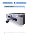
Table of Contents
What’s in the Box
1...What’s in the Box
2...Quick Start Guide
3...Design Overview
3...Input Gain Stage
3...Internal Power Plant
4...X1 Output Current Stage
4...Main Power Supply
4...Operation
4...Front Panel: Power
4...Front Panel: Display
5...Back Panel: Inputs
5...Back Panel: Outputs
6...Back Panel: Communication
7...Back Panel: Power
7...Specifications
8...Useful Tips
8...Warranty
8...Service Issues
• One Classic 250 stereo amplifier
• One 6 foot AC power cord
• One user’s manual and warranty
card
• One pair of gloves
• One spare 3 amp fast blow fuse for the
regenerator board (Power Plant)
and one spare 15 amp slow blow fuse
for the main circuitry.
• IMPORTANT: Be sure to save all
packing materials included with
your C250 as this will be required
if you ever need to ship the amplifier
for service or modification.
1
Quick Start Guide
Match the C250’s positive (red) and negative (black) terminals to the corresponding
speaker connections.
1. Turn off your pre-amplifier or any other
piece of equipment to which the C250 will
be connected.
6b. Mono Output: To connect the C250 to
your speaker when in mono mode, follow
the red text on the back panel. Connect
your speakers’ positive lead to the left
channel (+) and the negative lead to the
right channel (+).
2. Ensure that you have a proper pair of
audio interconnects for the input signal
and a pair of speaker cables to connect
the C250 to your speakers.
7. Locate the power cord supplied with
the C250 and plug it into the connection
labeled “AC Input.” The Classic 250 has
an auto-sensing input voltage circuit, so
the C250 is virtually plug-and-play in this
regard. For more information on input AC
voltage, see pages 7.
3. Unpack the C250 and place it on a
smooth surface. (As with any amplifier it
is not advisable to place on carpet or other
airflow restricting materials.)
4a. Stereo Input: Choose either the
single-ended (RCA) or balanced (XLR)
input connections on the
back of the C250. There
is a selector switch for
each channel to activate
the connector you have
chosen. Only one type
of input, RCA or XLR, will
work at a time. Be sure
to set both the left and
right channel to either
RCA or XLR input.
8. Plug the male end of
the power cord into your
wall receptacle. This
automatically engages
the regenerator and
voltage gain stage. The
meter display will light
up in yellow for a period
of 17 seconds during
this intial activation
phase. The Power button is purposefully kept
inactive during this time.
4b. Mono Input: Follow
the red text on the back
of the C250 for mono setup. Set the rear
panel selector switch on the back panel to
“Mono.” This deactivates the right channel
input connectors. Use the left channel input connectors to run your C250 in mono.
Don’t forget to set this input for RCA or
XLR.
9. After 17 seconds and the meter display
has gone dim, turn on the C250 by pressing the button in the center of the chassis,
below the meter display. Also, turn on the
pre-amplifier and any other piece of equipment needed to operate your system.
10. The C250 will power up in standby
mode for 40 seconds. During this period,
the front panel meter will light up in yellow and the PS logo in blue, indicating the
standby mode.
5. Connect the outputs of your pre-amplifier or source equipment to the inputs of
the C250 according to the instructions in
4a for stereo or 4b for mono.
6a. Stereo Output: Connect your speakers to the C250’s output terminals, labeled
“Right” and “Left.” Be sure to connect the
polarity of the speaker cables correctly.
11. After 40 seconds the meter will light up
in blue. The C250 is now fully operational
and ready to drive your speakers. Start
the music and enjoy!!
2
Design Overview
The Input Gain Stage
This critical element is, in large part, responsible for the way the amplifier sounds.
By carefully tuning the audio parameters
of the input gain stage we can tweak and
play with the amplifier until it sounds absolutely musical.
Based on the classic lines of the P600
Power Plant, this is built in true ‘battleship’
fashion. This 95 pound audio sculpture is
simply magnificent in its build quality and
attention to detail.
In the Classic 250, the input gain stage
consists of two gain blocks: a zero feedback JFET input stage and a zero feedback bipolar stage. Both of these stages
are fully differential.
The side heat sinks are on hinges and fold
down to expose the C250’s circuitry for
easier access to the internal circuitry.
No expense has been spared on the most
visible evidence of the Classic approach
to power amplification. The look exudes
finesse.
The input gain stage runs at extremely
high voltages. In fact, the 200 volts used
by this stage is one of the reasons why the
C250 sounds so open and musical even
during the loudest passage.
The front panel is a nearly two inch thick
combination of extruded aluminum panels
tied together both top and bottom with one
inch slabs of hand finished aluminum. The
entire assembly is then melded together to
form the luscious curves you see.
All the C250’s 30 dB of gain is produced
by the input gain stage. This stage is completely independent from the output current gain stage. The input stage is fed by
its own regulated power supply that gets
its power from a built in Power Plant.
Parts quality is second to none. Low ESR
capacitors, each with film and foil bypass
capacitors, 1% resistors throughout, 40
hand selected high current bipolar output
devices, two custom wound and individually serialized 800VA toroidal transformers, and the front panel meter is a custom
manufactured replica of the classic Simpson volt meters of years ago. Nothing has
been spared in the Classic 250.
Because the input gain stage has no interaction with the output stage, the Classic
250 sounds the same on virtually any loudspeaker load.
The Internal Power Plant
Our Power Plant AC regenerators have
revolutionized power within people’s
homes forever. Now it is available in a
specially tuned version designed to enhance the performance and long term reliability of the C250.
The design idea behind the Classic 250 is
based on the marriage of four discrete and
independent systems. The fact that each
of these systems is completely independent both physically and electrically from
the other is one of the keys to the Classic
250’s sonic success.
The 40 watt Power Plant inside the C250,
with its own discrete and custom wound
toroidal transformer, independently powers
the entire input gain stage and was hand
tuned to maximize the amp’s performance.
The four sections are:
• The input gain stage
• The internal Power Plant
• The output X1 stage
• The main power supply
After hours of listening tests we finally
settled on one of our original Power Plant
favorites, 120 Hz sine wave. This provides
the cleanest and most open sound for the
3
Operation
C250 amplifier, producing a much more
rich and open sound.
Front Panel: Power
The front panel of the C250 was designed
to bring both a level of elegance and simplicity into your system. The power button
(on/off) is located directly in the center,
below the meter display.
Having a Power Plant built into the Classic 250 to regenerate a clean AC signal for
the input gain stage is one of the factors
that sets this amplifier apart. It is worth
noting, however, that the Power Plant is
only regulating the input stage. Therefore,
additional levels of AC regeneration can be
implemented to improve the amplifier as
a whole, for example with a P1200 Power
Plant. In other words, a clean, well regulated AC power line will make a difference
with the C250.
Plugging the C250 into the wall activates
both the regenerator (power plant) and
voltage gain (input) stage. The meter display will light up in yellow for 17 seconds
while these two circuits activate, during
which the power button will not respond
to your touch. These sections are kept
powered up at all times. After the initial 17
second activation period, the yellow light
in the meter display will go dim. Still, the
output section has no power.
The X1 output current stage
Typically the output stage of a power
amplifier is tied to the input stage and
together they form a “team” to produce the
power. Not so in the C250. This revolutionary and one-of-a-kind current stage is
an absolutely separate and independent
standalone current converter. It has its
own power supply, its own feedback loop
and is physically separated from anything
else in the amplifier.
Pressing the power button will initiate the
power up sequence, which lasts for 40
seconds. During this period, the meter will
light up in yellow and the PS logo in blue,
indicating the standby status. It is not
advisable to try and play music during this
period.
The C250 can handle loads less than 2
Ohms and still breathe easily. To accomplish this we incorporated 20 high current
output devices per channel. Each of the
40 output devices in the Classic 250 can
handle 30 amps of power.
The C250 becomes fully operational once
the meter display lights up in blue. This
indicates that the C250’s output stage is
engaged. Once fully powered up, pressing
the power button again will turn the output
stage off.
The main power supply
Obviously the purpose of a power amplifier is to generate power. Pure, clean and
musical power that has no limitations.
Front Panel: Display
The front panel display window in the
C250 contains an analog meter that reads
several useful statistics.
Inside the C250 are two completely independent toroidal transformers and power
supplies and a short signal path to maintain the highest possible power quality.
The top line, labeled “DCV,” is a representation of the voltage that is available to the
output stage. There is a direct relationship
between this value and the input AC voltage. For example, feeding the C250 with
120 volts should present a DCV value of
80 volts.
Each of the two toroidal supplies is a monstrous 800VA transformer that is housed
under its own chassis, isolated from the
main body. These transformers feed a
robust 80,000 mFd’s of energy storage.
4
The center line, labeled, “%,” presents the
same information as above, but displayed
as a percentage. Therefore, a 120 volt
input should read 100%.
Stereo Input: Whether you are using a
pre-amplifier or a source component with a
built in processor, you will want to ensure
that the left output from that equipment
matches the “Left” of the C250 and likewise for the “Right.” Be sure to use the
inputs in matched pairs for example, use
both RCA inputs or both XLR inputs, but
never one of each.
The bottom line, labeled “Energy Storage,”
indicates the accepted voltage range to
achieve normal operation.
During loud passages, or if your AC line
temporarily sags, you may witness some
degree of fluctuation in the meter. If the
needle consistently resides somewhere
outside the accepted Energy Storage
range, you may elect to have an electrician
check your line voltage to ensure proper
operation of the Classic 250.
Mono Input: If you intend to use your
C250 in mono mode, which will require
one Classic 250 amplifier per speaker, you
must first switch the input selector on the
right channel to Mono. This deactivates
the right channel input. The left channel
connectors are now used for making input
connections while in mono. These instructions are also indicated on the back panel
in red text.
As discussed in the Front Panel: Power
section, a yellow meter indicates standby
and a solid blue meter indicates full operation. If the amplifier experiences a
problem, for example a short circuit or
over-voltage, the C250 will go into its fault
protect mode. This status is indicated by
the meter display flashing blue. If you
ever encounter this situation with your
C250, first check to make sure that all connections are seated properly. Then turn off
and unplug the C250 from the wall, allowing its circuitry to reset and power it back
up. If the amplifier is still indicating the
fault mode, please refer to the back of this
manual for service.
Back Panel: Outputs
There are four pairs of speaker terminals
on the back of the C250. Two pairs are
situated on the left channel side and two
pairs are situated on the right channel
side. There are two pairs of outputs per
channel for easier bi-wire connections
to your loudspeakers. Both pairs output
the exact same signal for their respective
channels, right or left.
The C250 uses WBT five-way binding
posts able to accept a spade, banana,
spade and banana, pin or straight wire.
Back Panel: Inputs
There are two sets of inputs to choose
from, single-ended (RCA) and balanced
(XLR).
The single-ended RCA connections are
a very high quality, gold plated connector designed specifically for PS Audio
components. The balanced XLR connector is easily identifiable as the larger
connector with three individual pins. The
C250 is a fully balanced design, thus use
of the balanced XLR inputs is the optimal
choice.
5
Stereo Output: The positive terminals
are indicated by a red connector and (+).
The negative terminals are indicated by a
black connector and (-). Connect the left
positive (red) of the C250 to the positive
(red or +) of your left speaker cable and
connect the left negative (black) of the
C250 to the negative (black, white or -) of
your left speaker cable. Do the same for
the right side terminals of the C250 and
your right speaker. Be sure to hook-up
your speaker(s) in phase with the C250; it
should be positive to positive and negative
to negative.
entiate between high frequency and low
frequency inputs). With two mono C250s
per speaker, one amplifier would be used
for low frequencies while the other would
be used for the high frequency connection
to your speaker.
Back Panel: Communication
The C250 includes the PS Buss, which
allows for a sophisticated method of communication between PS gear that supports
this protocol. Each PS product that has
the PS buss installed can communicate
with any other similarly equipped PS product.
Mono Output: Hooking up a speaker to a
C250 set for mono is slightly different. As
with the input connectors, follow the red
text to determine the appropriate connections.
The PS buss allows you to turn on and off
the C250 from another PS component that
is set as the master device.
To place the C250 on a network, you will
need to have it connected to another piece
of PS equipment that is properly interfaced
to a CE network.
In mono, the positive lead is established
with the (+) from the left channel and the
negative lead comes from the (+) on the
right channel. Either the top or bottom
connectors can be used, once again for
easier bi-wire hook-up.
The C250 can be assigned as single or as
one of many power amps in the system.
You can sequentially turn the unit on or off
from the push of a single button.
Other: Aside from standard stereo or
mono applications, the C250 can also be
applied in bi-wiring or bi-amping configurations. To bi-wire, simply add a second
set of speaker cables to the second set
of output binding posts and hook-up your
speakers according to that manufacturer’s
recommendation.
Also included on the back of the C250 is a
12-volt DC trigger. This device has been
provided for your convenience to incorporate the C250 into other types of automated systems. This 12-volt trigger is an input
trigger and will respond to an external
signal from 5-12 volts.
For bi-amping, you may use one C250 (in
stereo) or two C250s
(in mono) to drive each
of your speakers. With
one stereo C250 dedicated per speaker, the
left and right designations on the back of the
C250 can be substituted for “high” and “low”
(or whatever correlates
to the description your
speakers use to differ-
Back Panel: Power
The C250 is equipped with
the standard, internationally accepted 15 amp IEC.
This device is labeled, “AC
input.” With the supplied
power cord, or with another high-end after market cable like the PS Audio
Lab Cable II, connect the
C250 to a power source.
6
The C250 is internally equipped with a PS
Audio Power Plant. This circuit was specifically tailored for the C250 input stage.
The primary function of this power plant
is to regulate and optimize the power line
signal for the input stage, however you
may still choose to plug the C250 into a
PS Audio P1200 Power Plant to obtain
additional levels of enhancement. Otherwise, simply connect the C250 directly into
your wall receptacle.
The C250 is equipped with a 3 amp fast
blow fuse to provide protection for the
regenerator (power plant) board. This fuse
can be located where it says, “Regenerator Fuse.” There is another fuse to provide
protection for the main amplifier circuitry,
which has a 15 amp slow blow rating. This
fuse can be located where it says, “Main
Fuse.”
Specifications
Stereo 8 ohm power.........250 watts RMS
Stereo 4 ohm power.........500 watts RMS
Mono power...................1,000 watts RMS
You will find two spare fuses along with
this user’s guide should you need them.
To obtain specific information on how to
replace a fuse, or more importantly to determine if the fuse needs replacing, refer
to the service section at the end of this
manual.
THD+N.............................0.2% at full rated
power into 8 ohms, 20 Hz - 20 KHz
The C250 is capable of handling either
100-120 volts AC input or 220-240 volts
AC input. The input AC circuitry in the
C250 is auto-sensing. Therefore, the
Classic 250 will automatically recognize
the correct input voltage and make the appropriate internal adjustments to function
properly. There are no manual selections
or switches to be made by the user to select input voltage.
Max Input Level...........................1.5 Vrms
Frequency Response................+/- 0.1 dB
10 Hz - 22kHz
Dynamic Range..............................111 dB
Max Output Level......................45.5 Vrms
Max Gain...........................................30 dB
Max Power Consumption........1600 watts
Input impedance......................100 K ohm
Input connections.......pair each balanced
(XLR) and single-ended (RCA)
Output connections.............2 pairs 5-way
binding posts per channel
Dimensions...............17” W x 9” H x 20” D
Weight..............................................95 lbs
7
Useful Tips
Service issues
Should your unit ever require service or if
you have any technical questions about
the C250 (for example, how to replace
the fuse or what a flashing blue display
means), you must either contact your dealer (PS Audio if purchased direct) or your
PS Audio distributor. No equipment will be
received at our service facilities without an
attached RA number.
Speaker placement
Speaker placement, particularly in a twochannel setup, can be a critical element
in system performance. Once you have
installed the C250 in your system, we
would encourage you to re-evaluate the
loudspeaker’s positioning with respect to
toe-in, distance from the rear wall, and
distance from each other.
To look for additional tips that may improve your system, you can go to the PS
Audio web site at http://www.psaudio.com/
toolbox.asp and click on to the “Tips &
Tricks” section. There you will find a
number of informative articles on speaker
placement, system tuning and much more.
If purchased through an authorized PS
Audio dealer or distributor, the RA number
must be obtained by the dealer or distributor. If the product was purchased from PS
Audio direct, this can easily be obtained
by calling PS Audio at 720-406-8946 or by
contacting us via email at customerservice
@psaudio.com.
Warranty inside the U.S. and Canada
PS Audio’s warranty is 3 years parts and
labor, from the date of original purchase,
and is fully transferable. This means that
we warranty the product itself regardless
of ownership, new or used. For the official warranty statement please refer to
the warranty card included with this user’s
manual.
Warranty outside the U.S. and Canada
PS Audio has authorized distribution
in many countries of the world. In each
country, the authorized importing retailer or
distributor has accepted the responsibility
for warranty of products sold by that retailer or distributor. Warranty service should
normally be obtained from the importing
retailer or distributor from whom you purchased your product. In the unlikely event
of service required beyond the capability of the importer, PS Audio will fulfill the
conditions of the warranty. Such product
must be returned at the owner’s expense
to the PS Audio factory. Contact your PS
Audio distributor or the PS Audio customer
service department for more information.
PS Audio International, Inc.
4824 Sterling Dr.
Boulder, CO 80301
PH: 877-772-8340
FAX: 720-406-8946
www.psaudio.com
8