1
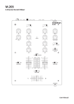
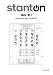
M.207
2-Channel Scratch Mixer with Effects
User Manual
Important Safety Instructions
1.
2.
3.
4.
5.
6.
7.
8.
9.
10.
11.
12.
13.
14.
15.
16.
17.
18.
19.
20.
21.
22.
Read Instructions – All the safety and operating instructions should be read before this product is operated.
Retain Instructions – The safety and operating instructions should be retained for future reference.
Heed Warnings – All warnings on the appliance and in the operating instructions should be adhered to.
Follow Instructions – All operating and use instructions should be followed.
Water and Moisture – The appliance should not be used near water – for example, near a bathtub, washbowl, kitchen sink, laundry tub, in a wet basement,
or near a swimming pool, and the like.
Heat – Appliance should be situated away from heat sources such as radiators, heat registers, stoves, or other appliances (including amplifiers) that produce
heat.
Power Sources – This product should be operated only from the type of power source indicated on the rating label. If you are not sure of the type of power
supply to your home, consult your product dealer or local power company.
grounding or Polarization – This product may be equipped with a polarized alternation-current line plug (a plug having one blade widerthan the other).
This plug will fit into the power outlet only one way. This is a safety feature. If you are unable to insert the plug fully into the outlet, try reversing the plug.
If the plug should still fail to fit, contact your electrician to replace your obsolete outlet. Do not defeat the safety purpose of the polarized plug.
Power-Cord Protection – Power-supply cords should be routed so that they are not likely to be walked on or pinched by items placed upon or against them,
paying particular attention to the cord in correspondence of plugs, convenience receptacles, and the point where they exit from the appliance.
Cleaning – The appliance should be cleaned only as recommended by the manufacturer. Clean by wiping with a cloth slightly damp with water. Avoid getting
water inside the appliance.
Non-use Periods – The power cord of the appliance should be unplugged from the outlet when left unused for a long period of time.
Object and Liquid Entry – Care should be taken so that objects do not fall and liquids are not spilled into the enclosure through openings.
Damage Requiring Service – The appliance should be serviced by qualified service personnel when:
A. The power-supply cord or the plug has been damaged; or
B. Objects have fallen, or liquid has been spilled into the appliance; or
C. The appliance has been exposed to rain; or
D. The appliance does not appear to operate normally or exhibits a marked change in performance; or
E. The appliance has been dropped, or the enclosure damaged.
Servicing – The user should not attempt any service to the appliance beyond that described in the operating instructions. All other servicing should be referred
to qualified service personnel.
Ventilation – Slots and openings in the cabinet are provided for ventilation and to ensure reliable operation of the product and to protect it from overheating,
and these openings must not be blocked or covered. The openings should never be blocked by placing the product on a bed, sofa, rug, or other similar surface.
This product should not be placed in a built-in installation such as a bookcase or rack unless proper ventilation is the manufacturer’s instructions have been
adhered to.
Attachments – do not use attachments not recommended by the product manufacturer as they may cause hazards.
Accessories – Do not place this product on an unstable cart, stand, tripod, bracket, or table. The product may fall, causing serious injury to a child or adult, and
serious damage to the product. Use only with a cart, stand, tripod, bracket, or table recommended by the manufacturer, or sold with the product. Any mounting
of the product should follow the manufacturer’s instructions, and should use a mounting accessory recommended by the manufacturer.
Replacement Parts – When replacement parts are required, be sure the service technician has used replacement parts specified by themanufacturer or have
the same characteristics as the original part. Unauthorized substitutions may result in fire, electric shock, or other hazards.
Safety Check – Upon completion of any service or repairs to this product, ask the service technician to perform safety checks to determine that the product is
in proper operating conditions.
This product is in compliance with EU WEEE regulations. Disposal of end of life product should not be treated as municipal
waste. Please refer to your localregulations for instructions on proper disposal of this product.
Carts and Stands – The appliance should be used only with a cart or stand that is recommended by the manufacturer. An appliance and
cart combination should be moved with care. Quick stops, excessive force, and uneven surfaces may cause the appliance and cart
combination to overturn.
The appliance coupler is used as the disconnect device, the disconnect device shall remain readily operable.
WARNINg
To reduce the risk of electric shock, do not expose this apparatus to rain or moisture. Ensure that the apparatus
is not exposed to splashing and that no objects filled with liquids, such as vases, are placed on the apparatus.
CAUTION
DO NOT OPEN
RISK OF ELECTRIC SHOCK
CAUTION: To reduce the risk of electric shock, do not remove any cover.
No user serviceable parts inside. Refer servicing to qualified personnel only.
The lighting flash with arrowhead symbol within the equilateral triangle is intended to alert the user to
the presence of un-insulated “dangerous voltage” within the product enclosure that may be significant
enough to constitute a risk of electric shock.
The exclamation point within the equilateral triangle is intended to alert the user to the presence of
important operation and maintance (servicing) instructions in the literature accompanying this
appliance.
CAUTION
To prevent electric shock, do not use this polarized plug with an extension cord, receptacle or other outlet
unless the blades can be fully inserted to prevent blade exposure.
ii
Contents
1.
2.
3.
4.
5.
Introduction ................................................................................................................................................................ 1
1.1. Welcome to the M.207! ................................................................................................................................................. 1
1.2. Overview ........................................................................................................................................................................ 1
Connecting the M.207 ................................................................................................................................................. 2
M.207 Description ....................................................................................................................................................... 3
3.1. Top Panel ........................................................................................................................................................................ 3
3.2. Front Panel ..................................................................................................................................................................... 6
3.3. Rear Panel ...................................................................................................................................................................... 7
Using the M.207 .......................................................................................................................................................... 8
4.1. Front Panel Controls ...................................................................................................................................................... 8
4.1.1. Fader Start ........................................................................................................................................................... 8
4.1.2. Selecting and Reversing a Channel Fader Curve .................................................................................................. 8
4.1.3. Selecting and Reversing the Crossfader Curve .................................................................................................... 8
4.1.4. Channel Reverse Function ................................................................................................................................... 8
4.2. M.207 Effects ................................................................................................................................................................. 9
4.2.1. The FXGlide™ Area .............................................................................................................................................. 9
4.2.1.1. The Slider Strip ...................................................................................................................................... 9
4.2.1.2. The Button Strip .................................................................................................................................... 9
4.2.1.3. The LED Strip ......................................................................................................................................... 9
4.3. Effects ........................................................................................................................................................................... 10
4.3.1. Automatic and Manual Filter ............................................................................................................................. 11
4.3.2. Phaser/Flanger .................................................................................................................................................. 12
4.3.3. Echo/Strobe ....................................................................................................................................................... 12
4.3.4. Pan/Transform ................................................................................................................................................... 13
4.3.5. Key ..................................................................................................................................................................... 13
4.3.6. Frequency Filters ............................................................................................................................................... 14
4.3.6.1. Filters as Effects .................................................................................................................................. 14
4.3.6.2. Filtering the Effect Sends .................................................................................................................... 15
4.4. FXGlide™ Slider Automation ........................................................................................................................................ 16
4.4.1. Manual Automation Recording ......................................................................................................................... 16
4.4.2. BPM Synchronized Automation Recording ........................................................................................................ 17
4.4.3. The Manual Button ........................................................................................................................................... 17
4.5. The Sampler ................................................................................................................................................................. 18
4.5.1. Manual Sampling ............................................................................................................................................... 18
4.5.2. BPM Synchronized Sampling ............................................................................................................................. 19
4.5.3. Playing Back a Sample ....................................................................................................................................... 20
4.5.4. Erasing a Sample ............................................................................................................................................... 20
Troubleshooting ......................................................................................................................................................... 21
Registration Card .............................................................................................................................................................. 22
Stanton Warranty ............................................................................................................................................................. 23
Specifications ................................................................................................................................................................... 24
iii
Introduction
1.
Introduction
1.1
Welcome to the M.207!
Thank you for purchasing the M.207.
Before starting, please check that you have received the following items:
•
•
•
•
M.207 unit
Power Cable
User Manual
Warranty Card
Now that you have checked that everything was included in the box, let’s talk about this exciting unit.
1.2
Overview
The M.207 is a revolutionary 2-channel scratch mixer that allows you to control FX parameters and automation by interacting with
the FXGlide™ touch controller (based on the same StanTouch technology as the SCS.3 series of MIDI controllers). The FXGlide™
controller is the heart of the M.207’s effects section, and gives you complete control over effects parameters, sampling, and
automation.
In addition, the innovative M.207 expands its effect flexibility through the new frequency-based effects sends. Now you can select
one or more frequency bands (Lo, Mid, Hi), and send just these frequencies to the FX processor.
The M.207 offers several significant features, such as the ability to sample, to synchronize its time-based effects to your track’s
tempo, to manually enter, tap, subdivide, or multiply the tempo to change the rate of modulation for FX parameters, to adjust the
Crossfader and Channel Faders curves, and to completely kill all three EQ bands. So let’s summarize the main M.207 features:
•
•
•
•
•
•
•
FXGlide™ Controller
Effect Automation
Frequency-based FX Routing
Beat Sync Sampling
Beat Sync Effects
Curve Adjustment for Crossfader and Channel Faders
Complete EQ kills
Ok, now that we’ve covered the M.207 basics, let’s get started!
1
Connecting the M.207
2.
Connecting the M.207
Before starting to connect the M.207, please read the Important Safety Instructions page and the following guidelines:
Study this setup diagram (Figure 2.1). Make sure all faders are at "zero,” the Master knob is turned all the way counterclockwise,
and all devices are Off.
Figure 2.1
First, connect all input sources. Next, connect your microphone and monitor headphones (located in the Front Panel, Figure 3.2).
Finally, connect the stereo outputs to the power amplifier(s) and/or audio receivers such as tape decks. Plug your mixer and other
devices into AC power. Now, switch everything on in the following order; audio input sources such as turntables or CD players first,
then your mixer, and finally any amplifiers.
When turning Off, always reverse this operation by turning Off amplifiers, then your mixer, and lastly any input devices.
2
M.207 Description
3.
M.207 Description
3.1
Top Panel (Figure 3.1)
Figure 3.1
3
M.207 Description
1.
Mic/Aux Input Selector: Selects the Microphone (MIC) or Auxiliary (AUX) input. You would use the AUX input for
connecting a 3rd audio source, like a CD Player, sampler, or another mixer (session input).
2.
Mic/Aux gain (gAIN): Adjusts the volume of the MIC or AUX input.
3.
Mic/Aux EQ: Adjusts the HI, MID, and LOW frequency levels of the MIC or AUX input.
4.
Mic/Aux FX (FX): Sends the signal to the internal FX processor.
Note Considering that Channels 1 (PH1/LN1) & 2 (PH2/LN2) contain the same controls and functionality; we will
only describe them once and duplicate the numbering:
5.
Input Selector Switch: Selects the Phono (PH) or Line (LN) input.
6.
Channel gain (gAIN): Adjusts the pre-fader volume of the PH or LN input.
7.
Channel EQ: Adjusts the HI, MID, and LOW frequency levels of the PH or LN input.
8.
Pan: Controls the Left/Right positioning of the signal within the stereo image.
9.
Channel FX (FX): Sends the signal to the internal FX processor.
10. Channel Fader: Controls the output level of the selected input (PH or LN).
11. Level Meter: Displays the pre-channel fader (10) volume.
12. Crossfader: Controls the audio signal that is sent to the outputs. When the Crossfader is set to 1 (hard left), only
channel 1 (PH1/LN1) will be sent to the outputs and when is set to 2 (hard right), only channel 2 (PH2/LN2) will be
sent to the outputs. So if the Crossfader is centered, both channels will be sent to the outputs so you are able to
fade (mix) or cut (scratch) between channels 1 & 2 signals.
13. Frequency FX (LOW, MID, HI): The LOW, MID, and HI buttons can be used to route each particular frequency bands
to the FX processor, or as effects themselves.
14. Automatic and Manual Filter effect (A.FILTER/M.FILTER): If this button is pressed and released, the AUTO FILTER
effect is enabled. When the button is held, it will switch between the MANUAL, HI-PASS, and LOW-PASS filter’s
modes. Release the button when the desired filter is selected.
15. Phaser/Flanger effect (PHASER/FLANgE): If this button is pressed and released, the PHASER effect is engaged.
If this button is pressed and held, then the FLANGER effect is engaged.
16. Echo/Strobe effect (ECHO/STROBE): If this button is pressed and released, the ECHO effect is engaged. If the
ECHO/STROBE button is pressed and held, then the STROBE effect is engaged.
17. Pan/Transform effect (PAN/TRANS): If this button is pressed and released, the PAN effect is engaged. If this button
is pressed and held, then the TRANSFORM effect is engaged.
18. Key effect (KEY): Changes the key of the song without affecting its tempo.
19. Sampler (SAMPLER): Pressing this button will engage the FX sampler mode.
20. Manual Mode (MANUAL): In any of the Auto Filter effects (like PHASER or AUTO FILTER), pressing the MANUAL
button will allow you to manually control the sweep of that effect by using the FXGlide™ touch slider. Pressing
MANUAL again will return the effect to its Auto mode.
4
M.207 Description
21. FX Parameter (PARAM): This button controls the parameter setting for the currently selected effect.
22. Wet/Dry: This button controls either the balance between the FX processor and the dry signal that is sent to the
master output, or it controls the balance between the frequency selectable effects and the unfiltered frequencies
(Frequency Wet/Dry).
23. Record (•): This button is used to initiate recording of both samples and FX automation.
24. Play/Stop (
): This button controls playback of FX automation recording or a looping sample.
25. Manual/Auto Mode (MAN/AUT): This button toggles the SAMPLER between Auto and Manual modes. Auto mode
in the Sampler uses the song BPM to determine the length of the sample. Manual mode will record the sample for
as long as you hold your finger on the trigger. This is explained in more depth later in the manual.
26. BPM: This button toggles between AUTO and MANUAL BPM modes.
a.
AUTO BPM: In this mode, the tempo is determined from the music source (default setting). BPM detection is
set to Auto by default. If you have left AUTO BPM and wish to return, simply press and hold the BPM button
until the BPM readout blinks (about 2 seconds). You will see the letter in front of the BPM readout on the LCD
change from M to A.
b. MANUAL BPM: To enter this mode, just tap on the BPM button. You will see the letter M appear in front of the
BPM in the LCD readout to indicate that you are now in manual BPM mode.
27. 1/2 Beat Division (1/2): This button divides the current tempo by 2.
28. 2X Beat Multiplication (2x): This multiplies the current tempo by 2.
29. LCD display: This 8-character displays BPM, FX parameters, and other related data.
30. FXglide™: The FXGlide™ Area allows you to control FX parameters and data entry by simply touching one of its 2
distinct areas (one is a “slider” and the other a row of buttons). Its LED indicators not only display the current state
of the parameter that it is controlling but also things like automation data. The markings located on the middle
strip of the FXGlide™ Area denote separate button areas, which can be used for everything from playing samples to
selecting beat divisions for BPM synchronized effects. There are tactile guides between the buttons to make it easier
for you to press the desired area.
31. FX Engage: This button sends or bypasses the effects to the Master output.
32. Lock: Pressing this button locks the FXGlide™, keeping its value from being accidentally changed.
33. Master Level: Controls the overall output level.
34. Headphone Level: Adjusts cue volume.
35. Cue Source (Pre, Post, Master): This switch allows you to select three headphone sources: PRE, POST, or MASTER.
On this feature, PRE and POST refer to the Crossfader (12). In PRE position, the signal selected by the CUE PAN
FADER (36) will be monitored (pre-line fader, pre-crossfader) as a stereo signal in the headphones. In the POST
position the signal is (pre-line fader, post-crossfader), so the signal received in the headphone depends on the
position of the Crossfader. In MASTER position, the signal monitored will be pre-master volume (post-faders),
meaning the signal will still be present in the headphone even if the Master volume control is turned down.
36. Cue Pan: Fades the headphone output between channels 1 and 2. This allows you to preview a mix, before bringing
up Channel Faders or moving the Crossfader.
37. FX Cue: Allows you to monitor FXs in the headphones.
5
M.207 Description (Front Panel)
3.2
M.207 Description - Front Panel (Figure 3.2)
Figure 3.2
Note Considering that Channels 1 (PH1/LN1) & 2 (PH2/LN2) contain the same controls and functionality; we will only describe
them once and duplicate the numbering:
1.
Fader Start (FDR START): Switches the FADER START ON/OFF. This feature is used to trigger playback on a connected
CD Player when the fader is used.
2.
Fader Curve (FDR CURVE): This knob selects between a LONG or SHARP fade for the corresponding line fader
depending on its position.
3.
Fader Reverse (FDR REVERSE): Switches the FADER REVERSE ON/OFF. When Fader Reverse is engaged, the bottom
of the fader is the loudest point, and the top cuts audio completely.
4.
Channel Reverse (CHAN REVERSE): Switches which Channel Fader controls Input 1 and 2. If the Channel Reverse
switch is in engaged (ON), then Fader 1 controls the level of Input 2, and Fader 2 controls the level of Input 1.
The functionality of the Crossfader is not altered and the pre-fader EQ is not channel reversed.
5.
Crossfader Curve (CF CURVE): This knob selects between a LONG or SHARP fade for the corresponding line fader
depending on its position.
6.
Crossfader Reverse (CF REVERSE): Switches the CROSSFADER REVERSE ON/OFF. This is often referred to as
“Hamster style.” When ON, the positions of channels 1 and 2 reverse, so moving the Crossfader full right
(for instance) would open audio on channel 1.
7.
Headphone Output: Standard 1/4” headphone output connector.
6
M.207 Description (Rear Panel)
3.3
M.207 Description - Rear Panel (Figure 3.3)
Figure 3.3
1.
Power Switch: Turns the mixer ON or OFF.
2.
AC IN: Input connection for the included power supply. While the power is switched OFF, plug the power supply
into the mixer first, and then plug it into the outlet.
3.
Fader Start: To use this function you need a CD player with the Fader Start feature and its related cable so you
can use the Crossfader to start and stop the CD player. The Fader Start switch (Front Panel, Figure 3.2, 1) activates
the Fader Start feature. When the Fader Start switch is in the ON position, this function allows the fader to
activate or return to the preset Cue Point on your compatible CD Player.
4.
Balanced Master output: TRS balanced (1/4”) connectors are typically used to connect to a P.A. mixer or an
amplifier for live performances, or a recording console.
5.
Unbalanced Master output: RCA connectors are typically used to connect to a home stereo, or to another
mixer with RCA inputs for practicing or team routines.
6.
REC: The record output is not affected by the Master volume control. It can be used to record to a computer,
CD, MD, & tape recorder, even while the master volume is turned down.
7.
Aux: This AUX LINE In allows you to connect CD & DVD players, iPods, etc. Just switch the MIC/AUX Input Selector
(Top Panel, 1) to AUX.
8.
Line Inputs: Unbalanced RCA jacks for connecting stereo audio from line level sources such as CD players,
Hi-Fi VCRs, cassette decks, DAT machines, laser discs, tuners, Mini Discs, even synthesizers or other mixing
consoles. Plug mono audio sources into both Left and Right inputs using a "Y" cable connector.
9.
Phono Inputs: Plug your turntables in here. When these connectors are used, your signal is fed directly to the
high-quality RIAA phono pre-amplifiers. Only connect turntables here. Line level sources will overload the
sensitive phono pre-amps and will cause distortion.
10. ground connector: To eliminate electrical hum, connect the ground cable from your standard turntable ground
post to the M.207 ground terminal. Some turntables (like the Stanton STR8.150) do not require grounding wire.
11. Microphone Input (Mic): Connect a standard unbalanced (1/4") microphone.
7
Using the M.207
4.
Using the M.207
4.1
Front Panel Controls (Figure 4.1)
Figure 4.1
4.1.1
Fader Start
Fader start enables the Crossfader on the M.207 mixer to start and stop playback on a CD player. To use this function you need a
CD player (like Stanton’s C.324) with the Fader Start feature and its related cable. You can use this feature to trigger playback on a
deck that might be just out of physical reach or to do a fader based beat juggle between 2 decks.
The Fader Start switch activates the Fader Start feature. When the Fader Start switch is in the ON position, this function allows the
fader to activate or return to the preset Cue Point on your compatible CD Player.
Now, let’s customize the channel and Crossfader curves;
4.1.2
1.
2.
4.1.3
1.
2.
4.1.4
Selecting and Reversing a Channel Fader Curve
Use the Fader Curve (FDR CURVE) knob to select between a LONG, MID, or SHARP fade for the corresponding
Channel Fader.
To reverse the Channel Fader direction, set the Fader Reverse (FDR REVERSE) switch to the ON position. Moving
the Channel Fader down will increase the volume and moving it up will decrease the volume.
Selecting and Reversing the Crossfader Curve
Use the Crossfader Curve (CF CURVE) knob to select between a LONG, MID, or SHARP fade for the Crossfader.
To reverse the Crossfader direction, set the Crossfader Reverse (CF REVERSE) switch to the ON position. In this
case, when the Crossfader is set to 1 (hard left), Channel 2 will be assigned and when is set to 2 (hard right),
channel 1 will be assigned.
Channel Reverse Function
Set the Channel Reverse (CHAN REVERSE) switch to the ON position. Channel Fader 1 will control the level of Input 2, and Channel
Fader 2 will control the level of Input 1.
8
M.207 Effects
4.2
M.207 Effects
In this section of the manual, we will show you how to use the main M.207 effects – from the Auto Filter to the Transform effect.
Let’s get ready to tweak!
4.2.1
The FXglide™ Area
This is the main control for the effects in the M.207 and it is separated into 3 components – the Slider Strip (A),
the Button Strip (B), and the LED Strip (C). (Figure 4.2)
Figure 4.2
4.2.1.1 The Slider Strip
The Slider Strip (A) is like a virtual fader that moves up and down with your finger and it is used to change a parameter that is a
continuous range of values (like 1-100, or 20 Hz to 20 kHz). The Slider Strip is absolute, meaning that if a range from 0-100 is being
controlled, 0 is always the bottom and 100 is always the top. Touching a specific point on the slider results in a specific value being
generated.
4.2.1.2 The Button Strip
The Button Strip (B) is a vertically aligned row of 5 buttons. These buttons have different uses depending on which effect is selected,
but in all cases, the values go from top (greatest) to bottom (least). Buttons are generally used to choose things like beat divisions
(4/1, 2/1, 1/1, ½ for instance), or to trigger samples.
4.2.1.3 The LED Strip
The LED Strip (C) is a column of LEDs that gives visual feedback on the different FXGlide™ functions and effects parameters.
For instance, with the PHASER effect selected, it will tell you which beat division is currently selected. If automation is active, it will
give you a visual representation of that particular automation. The LED Strip it is not touch sensitive.
9
Effects
4.3
Effects
There can be 2 effects per button. One effect is located at the top and the other at the bottom of the button.
For example, A.Filter/M.Filter, Phaser/Flanger, etc.
Pressing the button once triggers the top effect (the button lights up solid). (Figure 4.3)
Figure 4.3
Pressing and holding the button engages the bottom effect (the button will blink to
indicate that the lower effect is engaged). (Figure 4.4)
Figure 4.4
To send an effect to a channel, the CHANNEL FX button must be pressed on that channel.
(Figure 4.5)
Figure 4.5
An FX button will light up red to let you know that it is active. Having the
FX button engaged on a channel will allow you to cue the effects on that channel, but
will not send the effect to the master output unless you press the
FX ENGAGE button (it will blink blue to let you know it is active). (Figure 4.6)
Now let’s look at the effects!
Figure 4.6
10
Automatic and Manual Filter
4.3.1
Automatic and Manual Filter (A.FILTER/M.FILTER)
A.Filter (Figure 4.7)
Figure 4.7
Auto Filter is a sweeping filter that moves based on the BPM. The FXGlide™ Button Strip
gives you 5 different sweep lengths, from 16 beats (16/1) to 1 beat (1/1). Pressing
WET/DRY will give you control over the ratio of effect audio to “normal” audio.
This is good if you want to make the effect a little more subtle. Pressing the PARAM
button will give you control over the amount of resonance in the Auto Filter.
A lot of resonance will make the effect much more noticeable, adding high frequency
harmonics at the top of the sweep and low frequency harmonics at the bottom.
M.Filter (Figure 4.8)
There are 3 filters available under the manual filters – the Manual Filter, Hi-Pass Filter,
and Low-Pass Filter. To scroll between them, hold down the M.FILTER button.
Figure 4.8
Manfltr
The Manual Filter is a variable notch filter that sweeps as you move your finger across the FXGlide™ Slider Strip.
It gives you a 20 kHz (top) to 5 Hz (bottom) sweep range. Like the Auto Filter, this filter offers resonance via the PARAM button, and
WET/DRY adjustment.
Hi-Pass
The High-Pass Filter rolls off frequencies lower than the point indicated in the LCD screen. So, if the value in the LCD is 2.75 kHz,
then only frequencies above that are being heard. PARAM offers resonance, and WET/DRY handles effect mixing.
Low-Pass
This works the same way as the Hi-Pass filter does, but instead only allows frequencies below the indicated frequency to be heard.
The PARAM and WET/DRY controls work the same as the other Manual Filter effects.
11
Phaser/Flanger
4.3.2
Phaser/Flanger (PHASER/FLANgE)
Phaser (Figure 4.9)
The Phaser is a sweeping notch filter that moves in time with the BPM. You are able to
select the Sweep lengths (from 16 beats to 1 beat) via the FXGlide™ buttons.
The PARAM button adds resonance to the filter, and the WET/DRY button controls the
amount of effect mix.
Figure 4.9
Flange (Figure 4.10)
Figure 4.10
4.3.3
The Flanger gets its sound by doubling the audio and delaying one copy slightly. You can
also hear this effect manually by playing 2 copies of the same record at the same speed.
It is a more pronounced and stronger effect than a Phaser usually is. The PARAM button
controls the depth of the Flanger effect, and the WET/DRY button controls the effect mix.
Like the Phaser, the Flanger is beat synchronized and offers sweep intervals from 16 beats
to 1 beat in length.
Echo/Strobe (ECHO/STROBE)
Echo (Figure 4.11)
Figure 4.11
This is a delay effect. The delay interval is determined by the setting in the
FXGlide™ Button Strip (from 4 beats long to a quarter of a beat long). The PARAM button
controls the amount of signal fed into the echo. A small PARAM value results in a shorter
and quieter echo – longer PARAM values produce longer and louder echoes. WET/DRY
controls the effect mix.
Because all of the effects on the M.207 are post fader, you can scratch using the
Crossfader, Channel Faders, or even the line switches and hear the echo tail off when
you cut the signal.
Strobe (Figure 4.12)
Figure 4.12
The Strobe effect is a simple version of the popular beat slicer effect. When first selected,
it does not make any noticeable difference in sound. The effect is only introduced when
you interact with the FXGlide™ Button Strip. Pressing on one of the 5 button areas will
play back a looping “slice” of the audio that is the length indicated in the LCD.
Available slice divisions are 1 beat, 1/2 beat, 1/4 beat, 1/8 beat, and 1/16 beat (arranged
from top to bottom). Slice lengths are determined based on the active BPM and the
division selected. Using the Strobe, you can achieve effects ranging from simple beat
juggles (using the higher values) to full on beat mangling. Both PARAM and WET/DRY
buttons affect the amount of effect present in the signal.
12
Pan/Transform
4.3.4
Pan/Transform (PAN/TRANS)
Pan (Figure 4.13)
Figure 4.13
The Pan effect sweeps the audio left and right to the beat of the music.
The sweep interval is determined by the value selected on the FXGlide™ Button Strip,
ranging from 16 beats to 1 beat in length. The PARAM value controls the shape of the
sweep. A high value produces a very sharp square wave, and a low value creates a
smooth sounding sine wave. WET/DRY controls how much of the audio is processed by
the Pan effect. At a setting of 100%, the song will appear to move between the left and
right speakers. At a lower setting, the WET/DRY ratio can create a subtle shifting of the
stereo image that is perfect for breakdowns.
Trans (Figure 4.14)
Figure 4.14
4.3.5
Transform sounds like someone is turning the channel On and Off rapidly.
It is named for the scratch technique of the same name. The speed of the effect is
determined by the active BPM and the beat division selected on the FXGlide™ Button
Strip. The PARAM button changes the gap length, with a high value giving long gaps and
short stabs of audio, and a low value giving you short gaps and long chunks of audio.
The WET/DRY parameter controls the amount of the Trans effect in the audio signal.
Key (Figure 4.15)
This allows you to change the key of the song without changing the pitch.
By default, the range is +/-9%. This range is manipulated using the FXGlide™ Slider Strip,
with the center of the slider being “0” (no effect). You can use this feature to match the
key of 2 songs so they mix more smoothly, to scratch samples, etc.
Figure 4.15
The PARAM button allows you to change the key range from 5% to 16%.
The WET/DRY parameter is used to adjust the ratio of effect audio (in fact, it can actually
change the effect radically). At 100%, the audio in the channel is totally key adjusted.
At a value less than 100%, the sound doubles and slightly delays, creating effects ranging
from a slight flange to a very creepy “madhouse” sound.
13
Frequency Filters
4.3.6
Frequency Filters
The M.207 has 3 frequency filters at the top of the effect area. (Figure 4.16)
They can act as effects themselves, offering “reverse EQ kill” functionality,
or they can be used to limit the frequency ranges being sent to an effect.
Let’s go over each case separately.
Figure 4.16
4.3.6.1 Filters as Effects
When you press one of the Frequency Filters, you will only hear the corresponding frequency range. Therefore, if you press the
MID filter, the audio will change and you’ll hear only the Mid range frequencies – kind of like an old telephone sound. Likewise, the
LOW and HI buttons will change the audio so that only the low or high frequencies are present. Like the other effects on the M.207,
these filters are adjustable via the PARAM and WET/DRY buttons. Unlike the other effects, to access the PARAM and WET/DRY
functions on the Frequency Filters, you need to be holding down the corresponding filter button before pressing the modifier
buttons.
These filters behave in much the same way that the M.Filter effects do. HI is a High-Pass Filter and PARAM controls the roll off
point. MID is a notch filter and PARAM controls the notch frequency. LOW is a Low-Pass Filter, where PARAM controls the roll off.
Therefore, if we wanted to adjust the Mid filter’s frequency, we would press and hold the MID button, then press the PARAM button.
You will see the MID button blinking to indicate that it is being edited. Moving your finger along the FXGlide™ Slider Strip will give
you a frequency from 20 kHz down to .05 Hz.
The WET/DRY parameter works in the same way. To adjust it, press and hold the frequency button (either HI, MID, or LOW) and
press the WET/DRY button. The FXGlide™ Slider Strip will allow you to dial in a setting from 0-100%. Just like editing PARAM, the
corresponding frequency button will flash when the WET/DRY parameter is being edited.
14
Filtering the Effects Sends
4.3.6.2 Filtering the Effect Sends
These buttons are also able to filter the frequencies being sent to a selected effect. For example, this could be used to add shimmer
to the high end by running it through the flange or to send just the midrange to the echo effect to accentuate a vocal. Several cool
effects can be achieved by using the frequency filters along with effects. The process goes like this…
1. Select the effect you want to use. (Figure 4.17) You can use the FX Cue function to
hear it without sending it to the main outputs (just have the CHANNEL FX ON but the
FX Engage button OFF).
Figure 4.17
2. Select the frequency range you want to send the effect to. (Figure 4.18)
In this case, we are sending it to the Mid range frequencies. When you first select the
frequency range, it will sound like the filter is engaged but the effect is not. This is normal.
Figure 4.18
3. Now, press the WET/DRY button and move the
value down to around 50% using the FXGlide™
Slider Strip (Figure 4.19) You will hear the sound
return to a more normal state, and the effect will
be present only in the selected frequency range.
Do not forget to press the WET/DRY button again
to get out of Edit mode. There are all kinds of
interesting effects available when you start
playing around with the frequency filters.
Figure 4.19
15
FXglide™ Slider Automation
4.4
FXglide™ Slider Automation
Many of the effects on the M.207 are beat synchronized. In most cases, the effect is modulated using a smooth sine wave.
However, you are able to manually input a modulation pattern of your own. Automation time can either be BPM based, or manually
done. Let’s explore the automation process more closely.
4.4.1
Manual Automation Recording
To manually record an automation sequence, press the MAN/AUT button so the M.207
Record mode is set to Manual. There is a LED above the PLAY/STOP button that will light
green to indicate Manual. (Figure 4.20) If it’s already green, you are in Manual and can
skip this step.
Figure 4.20
With one finger, you will need to press and hold the RECORD button
Figure 4.21 (1). Take your other finger and start moving it across the FXGlide™ slider (2).
When your finger first touches the strip, you will see the LCD display say AUTOREC to
indicate that automation is being recorded.
Any time you lift your finger off the slider strip, the FXGlide™ value will go to “0.” This
can be cool if done on purpose, but it can also cause the effect to sound glitch in some
cases.
To make a smooth sounding pattern, keep your finger on the slider strip until you release
the RECORD button. Once you release the RECORD button, the M.207 will immediately
stop recording and switch to play mode. The PLAY/STOP button will light green, the LCD
will show AUTOPLAY to indicate an automation sequence is being played back, and you
will see the pattern you just created moving in the FXGlide™ LED strip. If an effect is
engaged, you will hear the pattern you just made working on the effect.
Figure 4.21
To return to the default sine wave automation, press the PLAY/STOP button to turn it OFF. To re-activate that automation, just press
PLAY/STOP again. The automation will remain in memory until a new pattern is created or the M.207 is turned OFF.
16
BPM Synchronized Automation Recording
4.4.2
BPM Synchronized Automation Recording
Before to make a BPM synchronized automation make sure the M.207 is in Auto
Recording. Press the MAN/AUT button Figure 4.22 (1) until the red LED above the
PLAY/STOP button lights. If it is already red, you can skip this step.
Press the RECORD button (2). The FXGlide™ LED strip as well as the RECORD button will
blink to let you know you have started the recording process. To determine how long
you want to record, press one of the buttons in the FXGlide™ Button Strip and select any
of the available length ranges from 16 beats (the top button), to one beat (the bottom
button).
Figure 4.22
Once a beat division is selected, it will appear in the LCD screen and the FXGlide™ LED
strip will stop blinking. This indicates that the M.207 is ready for you to input your
automation. Recording will begin when you first touch the FXGlide™ Slider Strip, and
you will see AUTOREC appear in the LCD display. (Figure 4.23) When recording your
automation sequence, it is a good idea to count the beats in your head so you know
how long you have.
If the recording stops at a different point on the FXGlide™ Slider Strip than it started at,
there will be an abrupt jump between those 2 points when the automation plays back.
In some cases, this can sound good, but in others not so good – so keep this in mind
while you are doing your recording.
Figure 4.23
Remember that any time you lift your finger off the slider strip, the FXGlide™ value will go to “0.” To make a smooth sounding
pattern, keep your finger on the slider strip until the recording completes.
Once the recording stops, the M.207 will start playing back the automation sequence you just recorded. The PLAY/STOP button will
light green to let you know it is playing back an automation sequence, and you will see the FXGlide™ LED strip play back that
automation as well. If an effect is engaged, you will hear the pattern you just made controlling the selected effect. To return to the
default sine wave automation, press the PLAY/STOP button to turn it OFF. If you wish to re-activate that automation, just press
PLAY/STOP again. The automation will remain in memory until a new pattern is created or the M.207 is turned OFF.
4.4.3
The Manual Button
While not strictly an automation feature, the MANUAL button deserves a mention here.
When a BPM synchronized effect is active, you can stop the default or automated
playback and manually control the effect parameter with your finger in real time. To use
this feature, first engage an effect (e.g., Phaser). With the Phaser effect active, press the
MANUAL button. (Figure 4.24)
When you press the MANUAL button, the sweeping of the effect stops. This is normal.
Now use the FXGlide™ Slider Strip to manipulate the effect. Pretty cool, especially as
you get lower on the FXGlide™ Slider Strip. You can use the FLANGER in Manual mode
and tap on the FXGlide™ Slider Strip to achieve a robotic sounding effect. Try using it
with other effects as well.
Figure 4.24
17
The Sampler
4.5
The Sampler
In addition to the Effects section, the M.207 also comes with a built-in 5-bank sampler. Samples can be recorded manually, or
lengths can be determined according to the active BPM and the selected beat division. Sample playback can be either one shot or
looping, and samples stay in memory until either the M.207 is turned OFF or they are erased by the user.
Like with FX slider automation, the sampler on the M.207 will work either in Manual mode, or in an Automatic mode. Let’s cover
Manual Sampling first.
4.5.1
Manual Sampling
Make sure that recording is set to Manual mode. Press the MAN/AUT button
(Figure 4.25) to toggle the LEDs above the PLAY/STOP button between AUTO and
MANUAL. Make sure that the green MANUAL LED is lit.
Figure 4.25
Press the SAMPLER button. Figure 4.26 (1)
To arm recording, press the RECORD button (2). It will flash to let you know you are ready
to record. On the FXGlide™ Button Strip there are 5 button areas, and each one can store
a separate sample.
Press and hold one of the FXGlide™ buttons and recording will begin (3).
When recording a sample, the word RECORD will appear in the LCD display. Recording
will run for approximately 8 seconds, or until you take your finger off the button.
The M.207 will still be in Record mode, so if you want to record more samples, feel free
to do so. If you try to record a sample in a slot that already has a sample, then the LCD
will let you know by flashing the words NO ERASE.
Figure 4.26
18
BPM Synchronized Sampling
4.5.2
BPM Synchronized Sampling
Press the SAMPLER button Figure 4.27 (1). This puts you into SAMPLER mode and allows
you to play back any samples you already have stored in the sample slots. Set the Record
mode to AUTO by pressing the MAN/AUT button (2). The red AUTO LED will light up to
let you know you are in the right mode.
Figure 4.27
To enter Recording, press the RECORD button. It will flash to tell you it is ready to record.
Using the FXGlide™ button area, select one of the 5 beat divisions (from 16 beats to 1
beat). (Figure 4.28)
The selected beat division will flash briefly on the LCD screen. You are now ready to
create a sample. Press any of the 5 button areas and a sample will record to that
particular slot. Considering that recording is still armed, feel free to record more samples
at the same beat division. To change beat divisions, exit and re-enter Record mode.
Like in Manual mode, if you try to record a sample in a slot that already has one, the
LCD will let you know by flashing the words NO ERASE.
Figure 4.28
If a sample is not the correct length, you might want to erase that sample and try again. If the automatically generated BPM is not
generating perfect loops (this can be true for rhythmically complex music), you might try tapping the BPM manually or via Manual
Sampling.
19
Playing Back a Sample
4.5.3
Playing Back a Sample
To play a sample, touch one of the areas in the FXGlide™ Button Strip. (Figure 4.29)
Figure 4.29
When a sample is playing, the PLAY/STOP button will blink Figure 4.30 (1). There are 2
modes for sample playback – LOOP or ONE SHOT. To verify in which mode the sampler
is currently in or to select the sample playback mode press the PARAM button (2).
Figure 4.30
You can use the top 2 or bottom 2 buttons in the FXGlide™ Button Strip to select playback
modes. The top 2 buttons put the sampler into LOOP mode, and the bottom 2 put it into
ONE SHOT mode. (Figure 4.31)
Figure 4.31
4.5.4
Erasing a Sample
In either Auto or Manual Sampling, hold down the RECORD button Figure 4.32 (1) and
tap a button in the FXGlide™ Button Strip to erase the corresponding sample (2).
If a sample existed in that slot, you will see the word ERASE appears in the LCD screen.
If the slot was empty, the word ERASED will show instead.
Figure 4.32
20
Troubleshooting
5.
Troubleshooting
Problem / Symptom
Possible Cause / Solution
No Sound.
Is the power ON? Based on your connections, check that you
have properly set the Input Selector Switch. Make sure that the
Input Gain, Channel Fader, and Master output are turned up.
Make sure the channels are properly assigned to the Crossfader.
No Sound-Headphones.
First check that the Headphone Level knob is turned up, and then
check the Cue Source (Pre, Post, Master) and Cue Pan settings.
Mixer sounds noisy.
If a microphone is not being used, turn all its related controls
down.
Microphone doesn’t work.
Is the Mic gain turned up? Does the microphone require
phantom power? This mixer does not provide microphone
phantom power.
Sound is distorted-Line Input.
Turn down the Input Gain Control. Check EQ settings.
Sound is distorted-Phono Input.
Only plug turntables into this input, do not plug in CD players or
other Line Level sources. Turn down the Input Gain Control and
check EQ settings.
I’m not able to monitor the FX-Headphones.
Press the FX Cue button. If this did not solve the issue, check that
the FX button is pressed and that you have selected a specific
effect by pressing on its related button.
The Channel Fader does not react as expected.
Please check the Channel Fader Curve settings (Front Panel).
The Fader Start feature does not work.
Are you using a CD player that includes that feature?
Are you properly connecting the Fader Start cable?
Is the Fader Start switch set to ON?
Check the Crossfader position.
I hear hum.
Make sure you are using good shielded audio cables. Some less
expensive audio cables can be susceptible to hum and
interference. Keep your audio cables away from AC power cables
and AC transformers. Make sure the mixer is not mounted too
close to high power amplifiers or lighting equipment power
supplies or ballasts. Make sure your turntables are properly
grounded to the back of the mixer if they include a grounding
wire.
I hear feedback.
If you are using a microphone, make sure that you are not too
close to the speakers or headphones. If you hear feedback on
the Phono Input, then the turntable may be mounted to close
to the speakers and/or subwoofer. Also, make sure the turntable
base is placed on a surface that does not vibrate or resonate
easily when the speakers are turned up loudly.
21
Registration Card
Thank you for choosing Stanton!
Your satisfaction is extremely important to us. We proudly stand behind the quality of our work and appreciate that you put your trust in us.
Registering your product will help us guarantee that you are kept up to date on our latest advances.
Warranty Service in the United States:
Please contact Stanton Tech Support BEFORE sending your product. In some cases, our Tech Support team can resolve your problem immediately,
avoiding down time due to shipping delays. However, if Tech Support determines that a repair is needed; please call us at +1 (954) 949-9600 to
obtain a Return Authorization Number (RA#) PRIOR to shipping your product to us.
Warranty Service outside the United States:
To initiate a warranty repair, please contact the authorized Stanton dealer from whom you purchased your product, and follow the dealer’s return
policy.
Save your shipping boxes and all packaging materials!
For the fastest and safest product return to Stanton, please use the original shipping carton and packaging materials. Stanton cannot be responsible
for any damages incurred during the shipping process due to poor or inadequatepacking. Please remember to insure your shipment!
22
Stanton Warranty
Stanton Warranty
Through Stanton's authorized dealers around the World, Stanton, or one of Stanton's authorized distributors outside the U.S., will, without charge,
repair or replace, at the sole discretion of the entity responsible for making the repair or providing the replacement, any Stanton merchandise
proved defective in material or workmanship for a period of one (1) year following the date of original purchase. Exceptions to this warranty are
as noted below:
The warranty for mechanical parts which are subject to wear and tear are limited to either the earlier of thirty (30) days following the date of
original purchase or for 10,000 cycles for switches.
Stanton will warrant all replacement parts and repairs for ninety (90) days from the date of original shipment. Repairs made necessary by reason
of misuse, alteration, normal wear, or accident are not covered under this warranty.
Returns
Authorized Stanton dealers are only authorized to sell and distribute merchandise within a specific country. All goods requiring warranty repair
or replacement must be returned (freight prepaid if not hand-delivered) to the authorized Stanton dealer from whom the merchandise was
purchased and in the same country where the merchandise was purchased. For purposes of purchases made via the Internet, the merchandise
must be returned to the authorized Stanton dealer in the country where the authorized Stanton dealer which sold the merchandise to purchaser
is located and not the authorized Stanton dealer in the country where the purchaser is located or the country in which the merchandise was
received. Any returns to a non-authorized dealer or to an authorized Stanton dealer not in the same country as the merchandise was intended
to be sold or as set forth above will void this warranty.
To initiate a warranty repair, you must contact the authorized Stanton dealer from whom you purchased the merchandise, and follow such
authorized Stanton dealer's return policy.
Stanton assumes no risk and shall be subject to no liability for damages or loss resulting from the specific use or application made of the
merchandise. Stanton's liability for any claim, whether based on breach of contract, negligence, infringement of any rights of any party, or product
liability, and relating to the merchandise shall not exceed the price received by Stanton from your purchase of such merchandise. In no event will
Stanton be liable for any special, incidental or consequential damages (including loss of use, loss of profit and claims of third parties) however
caused, whether by the negligence of Stanton or otherwise. To the extent permitted by law and except as otherwise provided above, Stanton
disclaims any express or implied warranties of merchantability or fitness for a particular purpose.
The above warranty provides you with specific legal rights. You may also have additional rights, which are subject to variation from state to state
and country to country.
If there is a dispute regarding the warranty of merchandise that does not fall under the warranty conditions stated above, please include a written
explanation with the merchandise when returned pursuant to the terms and conditions set forth herein.
23
Specifications
Specifications
1. POWER:
AC 100 – 240 V, 50/60 Hz, 16 W
2. DIMENSIONS (H x W x D)
108.2 mm x 250 mm x 352.6 mm
10.82 cm x 25 cm x 35.26 cm
3. WEIgHT:
9.25 lbs / 4.2 kg
4. STANDARD TEST CONDITION:
Ambient Temperature: 22 +/- 2%
Relative Humidity: 65 +/- 5%
5. INPUT/OUTPUT IMPEDANCE & SENSITIVITY:
(EQ FLAT, UNITY GAIN (ALL GAIN, LEVEL AT CENTER, FADER MAXIMUM), FX OFF, LOAD=100K ohm)
5-1. Input Impedance and Reference Level:
Aux:
20K ohm /-10 dBV +/-0.1 dB (316 mV)
Line:
20K ohm /-10 dBV +/-0.1 dB (316 mV)
Phono:
47K ohm /-50 dBV +/-0.1 dB (3.16 mV)
Mic:
10K ohm /-50 dBV +/-0.1 dB (3.16 mV)
5-2. Output Impedance and Level:
Rec:
2.2K ohm /-10 dBV (316 mV) +/-2 dB
Master Unbal:
1K ohm /-10 dBV (316 mV) +/-2 dB
Master Bal.(Load=600 ohm)
600 ohm /-6 dBm (390 mV) +/-2 dB
Phones (Load=32 ohm)
33 ohm /-10 dBV (316 mV) +/-2 dB
6. FREQUENCY RESPONSE: (EQ FLAT, UNITY GAIN, FX OFF, LOAD=100K ohm)
Line, Aux:
20 Hz – 20 kHz +/-2 dB
Phono:
20 Hz – 20 kHz +2/-3 dB (RIAA)
Mic:
20 Hz – 20 kHz +2/-3 dB
7. THD + N: (EQ FLAT, UNITY GAIN, FX OFF, W/20 kHz LPF, LOAD=100K ohm)
Line, Aux:
Less than 0.03% @1 kHz
Phono:
Less than 0.1% @ 1 kHz (A-WEIGHTED)
Mic:
Less than 0.1% @ 1 kHz (A-WEIGHTED)
8. MAXIMUM INPUT: (1 kHz, THD=1%, EQ FLAT, UNITY GAIN, FX OFF, LOAD=100K ohm)
Line, Aux:
More than +14 dBV
Phono:
More than -26 dBV
Mic:
More than -26 dBV
9. MAXIMUM OUTPUT: (1 kHz, THD=1%, EQ FLAT, MAXIMUM GAIN, FX OFF, LOAD=100K ohm)
Master:
More than +18 dBV (8.0 V)
Rec:
More than +13 dBV (4.5 V)
Phones
More than +4 dBV (1.58 V) LOAD=32 ohm
10. NOISE FLOOR: (EQ FLAT, UNITY GAIN, FX OFF, W/20 kHz LPF, A-WEIGHTED, LOAD=100K ohm)
Line, Aux:
Less than -86 dBV
Phono:
Less than -75 dBV
Mic:
Less than -76 dBV
11. CROSSTALK: (EQ FLAT, UNITY GAIN, FX OFF, W/20 kHz LPF, A-WEIGHTED, MASTER = +14 dBV OUTPUT)
L.R Separation:
More than 70 dB @ 1 kHz for LINE, AUX and PHONO
Between Channels:
More than 86 dB @1 kHz for LINE (AUX) to LINE (AUX),MIC
More than 85 dB @ 1 kHz for LINE to PHONO
12. EQ: (UNITY GAIN, FX OFF, W/20 kHz LPF, LOAD=100K ohm)
Low
Mid
High
10 +/-2 dB, below -32 dB at 70 Hz
10 +/-2 dB, below -32 dB at 1 kHz
10 +/-2 dB, below -32 dB at 13 kHz
13. CHANNEL BALANCE:
Within 3 dB FROM 0 TO -40 dB
14. FADER KILL: (EQ FLAT, UNITY GAIN, FX OFF, W/20 kHz LPF, A-WEIGHTED, MASTER = +14 dBV OUTPUT)
Channel Fader:
More than 85 dB at 1 kHz
Crossfader:
More than 85 dB at 1 kHz
15. ACCESSORIES:
User Manual
1 pc
AC Power Cord
1 pc
24
Copyright © 2009 Stanton Magnetics, Inc.
M.207, STR8.150, and FXGlide are trademarks or registered trademarks of the Stanton Group.
All other trademarks are property of their respective owners, who are in no way affiliated with Stanton DJ or
SC System products. All information included in the User Manual is subject to change without notice.
+1 (954) 949-9600
LITS00052 10/05/2009


![PLAS A O ]-OR](http://vs1.manualzilla.com/store/data/005852706_1-5db0b7ed584537f0e62af161fb124638-150x150.png)