1
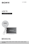
HX751E
Floating Marine Transceiver
Owner’s Manual
HX751E
Page 1
TABLE OF CONTENTS
1. GENERAL INFORMATION .................................................................................................... 4
1.1
INTRODUCTION ......................................................................................................... 4
2. ACCESSORIES ...................................................................................................................... 5
2.1
PACKING LIST ........................................................................................................... 5
2.2
OPTIONS ..................................................................................................................... 5
3. ABOUT THIS RADIO ............................................................................................................ 6
3.1
ABOUT THE VHF MARINE BAND .......................................................................... 6
3.2
EMERGENCY (CHANNEL 16 USE) .......................................................................... 6
3.3
CALLING ANOTHER VESSEL (CHANNEL 16) ....................................................... 7
3.4
OPERATING ON CHANNEL 13 ............................................................................... 7
3.5
OPERATING ON CHANNEL 67 ............................................................................... 8
3.6
IMPORTANT SAFETY INFORMATION ....................................................................... 8
4. GETTING STARTED .............................................................................................................. 9
4.1
RADIO CARE .............................................................................................................. 9
4.2
BATTERIES AND CHARGERS ................................................................................. 9
5. CONTROLS AND INDICATORS ......................................................................................... 13
5.1
CONTROLS AND SWITCHES ................................................................................ 13
5.2
INDICATORS ............................................................................................................. 17
6. BASIC OPERATION ............................................................................................................ 19
6.1
PROHIBITED COMMUNICATIONS ......................................................................... 19
6.2
INITIAL SETUP ......................................................................................................... 19
6.3
RECEPTION .............................................................................................................. 19
6.4
TRANSMISSION ....................................................................................................... 20
6.5
USA, CANADIAN, AND INTERNATIONAL CHANNELS ....................................... 21
6.6
SIMPLEX/DUPLEX CHANEL USE .......................................................................... 21
6.7
KEYPAD LOCKING .................................................................................................. 21
6.8
PRESET CHANNELS (0 ~ 9): INSTANT ACCESS ................................................ 22
6.9
MEMORY SCAN ....................................................................................................... 23
6.10 PRIORITY SCAN ...................................................................................................... 24
6.11 DUAL WATCH ........................................................................................................... 25
6.12 TRIPLE WATCH ....................................................................................................... 25
6.13 MEASURING WATER TEMPERATURE ................................................................. 26
6.14 ENABLING S.O.S STROBE OPERATION ............................................................. 27
7. MENU (“SET”) MODE .......................................................................................................... 28
8. INSTALLATION OF OPTIONS ............................................................................................ 31
8.1
FBA-38 ALKALINE BATTERY CASE ..................................................................... 31
9. ATIS SETUP .......................................................................................................................... 32
9.1
ATIS CH GROUP ....................................................................................................... 32
9.2
ATIS CODE PROGRAMMING ................................................................................... 33
10. MAINTENANCE .................................................................................................................... 34
10.1 GENERAL .................................................................................................................. 34
10.2 TROUBLESHOOTING CHART ................................................................................ 34
11. CHANNEL ASSIGNMENT ................................................................................................... 35
12. SPECIFICATIONS ................................................................................................................. 37
12.1 GENERAL .................................................................................................................. 37
12.2 TRANSMITTER ......................................................................................................... 37
12.3 RECEIVER ................................................................................................................ 37
Page 2
HX751E
Congratulations on your purchase of the HX751E! Whether this is your first
portable marine VHF transceiver, or if you have other STANDARD HORIZON
equipment, the STANDARD HORIZON organization is committed to ensuring
your enjoyment of this high performance transceiver, which should provide
you with many years of satisfying communications even in the harshest of
environments. STANDARD HORIZON technical support personnel stands behind every product sold, and we invite you to contact us should you require
technical advice or assistance.
We appreciate your purchase of the HX751E, and encourage you to read this
manual thoroughly, so as to learn and fully understand the capabilities of the
HX751E. Technical support information and assistance can be obtained in
Europe from our Website www.standardhorizon.co.uk
NOTE
Water resistance of the transceiver is assured only when the battery
pack is attached to the transceiver and MIC/SP cap is installed in the
MIC/SP jack.
Attention in case of use
This transceiver works on frequencies which are not generally permitted.
For frequency allocation, apply for a licence at your local spectrum management authority. For actual usList of the practicable area
age contact your dealer or sales
AUT BEL BGR CYP CZE DEU DNK
ESP EST FIN FRA GBR GRC HUN
shop in order to get your transIRL
ITA LTU LUX LVA MLT NLD
ceiver adjusted to the allocated frePOL PRT ROM SVK SVN SWE CHE
quency range.
ISL
LIE NOR
HX751E
Page 3
1. GENERAL INFORMATION
1.1 INTRODUCTION
The HX751E is a Submersible Floating 6-Watt portable two way marine transceiver. The transceiver has all allocated USA, International, or Canadian channels. It has emergency channel 16 which can be immediately selected from
any channel by pressing the [16/9] key.
The HX751E includes the following features: Memory Scanning, Priority Scanning, ATIS Mode for Inland Waterways in Europe, Battery Saver, easy-to-read
large LCD display, EEPROM memory back-up, Battery Life displayed on LCD,
and a transmit Time-Out Timer (TOT).
The HX751E transmitter provides a full 6 Watt of transmit power and also is
selectable to 5, 2.5, and 1 Watt to assist the user in ensuring maximum battery
life.
The HX751E supports ATIS mode which is used in the inland waterways of
Europe. Please contact your local PTT administration or Marine Authority to
obtain your ATIS number.
Page 4
HX751E
2. ACCESSORIES
2.1 PACKING LIST
When the package containing the transceiver is first opened, please check it
for the following contents:
HX751E Transceiver
CAT460 Antenna
FNB-V99LI 7.4 V, 1150 mAh Li-Ion Battery Pack
CD-39 Charger Cradle for HX751E
NC-88C/U 230VAC Wall Charger for CD-39
CLIP-19 Belt Clip
Owner’s Manual
2.2 OPTIONS
MH-73A4B
MH-57A4B
VC-24
VC-27
CN-3
CD-39
FNB-V99LI
FBA-38
NC-88C/U
Speaker/Microphone
Mini Speaker/Microphone
VOX Headset
Earpiece/Microphone
Radio-to-Ship’s-Antenna
Adapter
Charger Cradle
7.4 V, 1150 mAh Li-Ion
Battery Pack
Alkaline Battery Case
AC Wall Charger for the
FNB-V99LI
: “C” suffix is for use with 230 VAC (TypeC plug), and “U” suffix is for use with 230
VAC (Type-BF plug).
Note: Before operating the HX751E for the
first time, it is recommended that the battery be charged. Please see section “4.2.3
BATTERY CHARGING” for details.
HX751E
Page 5
3. ABOUT THIS RADIO
3.1 ABOUT THE VHF MARINE BAND
WARNING
The radio frequencies used in the VHF marine band lie between 156
and 158 MHz. The marine VHF band provides communications over
distances that are essentially “Line of sight” Actual transmission range
depends much more on antenna type, gain and height than on the power
output of the transmitter. On a fixed mount 25 W radio transmission
expected distances can be greater than 15 miles, for a portable 6 W
radio transmission the expected distance can be greater than 5 miles in
“Line of sight”.
The user of a Marine VHF radio is subject to severe fines if the radio is
used on land. The reasoning for this is you may be near an inland waterway, or propagation anomalies may cause your transmission to be heard
in a waterway. If this occurs, depending upon the marine VHF channel
on which you are transmitting, you could interfere with a search and
rescue case, or contribute to a collision between passing ships. For
channel assignments refer to page 35 section 11.
3.2 EMERGENCY (CHANNEL 16 USE)
Channel 16 is known is the International Distress and Calling Channel. An emergency may be defined as a threat to life or property. In such instances, be sure
the transceiver is on and set to CHANNEL 16. Then use the following procedure:
1. Press the PTT (Push-To-Talk) switch and say “Mayday, Mayday, Mayday.
This is _____, _____, _____” (your vessel’s name).
2. Then repeat once: “Mayday, _____” (your vessel’s name).
3. Now report your position in latitude/longitude, or by giving a true or magnetic bearing (state which) to a well-known landmark such as a navigation
aid or geographic feature such as an island or harbor entry.
4. Explain the nature of your distress (sinking, collision, aground, fire, heart
attack, life-threatening injury, etc.).
5. State the kind of assistance your desire (pumps, medical aid, etc.).
6. Report the number of persons aboard and condition of any injured.
7. Estimate the present seaworthiness and condition of your vessel.
8. Give your vessel’s description: length, design (power or sail), color and minute.
9. End the message by saying “OVER”. Release the PTT switch and listen.
10. If there is no answer, repeat the above procedure. If there is still no response, try another channel.
Page 6
HX751E
3.3 CALLING ANOTHER VESSEL (CHANNEL 16)
Channel 16 should be used as the calling channel for initial contact with another vessel, however its primary purpose is for emergency communications
and should be monitored at all times when not using other channels.
It is monitored by Coast Guard stations in all countries and other vessels.
The use of Channel 16 should be limited to making initial contact only. Calling
should not exceed 30 seconds, but may be repeated at 2 minute intervals.
Prior to making contact with another vessel, refer to the channel charts in this
manual and select an appropriate channel (working channel) for use after initial contact. Monitor the proposed channel to ensure you will not be interruptng
other traffic and then go back to Channel 16 to make your initial call.
When the calling chqannel 16 is clear, state the name of the vessel you wish to
call and then “this is” followed by the name of your vessel and your vessel
callsign. When the other vessel returns your call, immediately request another
channel by saying “go to”, the number of the other channel, and “over”. Then
switch to the new channel. When the new channel is not busy, call the other
vessel.
After a transmission, say “over”, and release the PTT (Push-To-Talk) switch.
When all communication with the other vessel is completed, end the last transmission by stating your Call Sign and the word “out”. Note that it is not necessary to state your Call Sign with each transmission, only at the beginning and
end of the contact.
Remember to return to Channel 16 when not using another channel. Some
radios automatically monitor Channel 16 even when set to other channels or
when scanning.
3.4 OPERATING ON CHANNEL 13
Channel 13 is used at docks, bridges and for maneuvering in port. Messages
on this channel must concern navigation only, such as meeting and passing in
restricted waters. In emergencies and when approaching blind river bends,
High power is allowed. Pressing the [H/L( )] key will change the power output from Low Power (1 Watt) to Medium (2.5 Watts), High (5 Watts), or Normal
(6 Watts). When you change from this channel then return to it, low power will
be automatically selected.
HX751E
Page 7
3.5 OPERATING ON CHANNEL 67
When channel 67 is used for navigational bridge-to-bridge traffic between ships,
Normal, High or Medium power may be used temporarily (in the USA band) by
pressing the [H/L( )] key. When you select this channel again, the transceiver will revert to low power.
3.6 IMPORTANT SAFETY INFORMATION
Please read this manual carefully to become familiar with the features of
this transceiver before using it for first time.
Do not transmit without an antenna connected to the radio.
When transmitting, hold the radio in a vertical position with its microphone
2.5 to 5 cm away from your mouth and keep the base of the antenna at
least 19 cm away from your head.
The radio must be used with a maximum operating duty cycle not exceeding 50 %, in typical Push-to-Talk (PTT) configurations. DO NOT transmit
for more than 50 % of total radio use time (50 % duty cycle). Transmitting
more than 50 % of the time can cause RF exposure compliance requirements to be exceeded.
The radio is transmitting when the red LED on the front panel of the radio
is illuminated. You can cause the radio to transmit by pressing the PTT
button or by using the VOX headset, if VOX is supported by the radio.
Always use the Vertex Standard authorized Battery Pack.
Risk of explosion if battery is replaced by an incorrect type. Dispose of
used batteries according to your local country instructions.
Only perform battery charging where the ambient temperature range is
between 0 °C to +45 °C. Charging outside of this range could cause damage to the battery pack.
Battery Pack should not be exposed to excessive heat such as sunshine,
fire or the like.
Always use Vertex Standard authorized accessories.
Vertex Standard shall not be liable for any damage or accidents such as
fire, leakage or explosion of batteries, etc., caused by the malfunction of
non-Vertex Standard accessories.
This radio generates RF electromagnetic energy during transmit mode.
This radio is designed for and classified as occupational use only, meaning it must be used only by individuals aware of hazards, and the ways to
minimize such hazards. This radio is not intended for use by the General
Population in an uncontrolled environment.
Page 8
HX751E
4. GETTING STARTED
If the radio has never been used, or its charge is depleted, it may be charged
by connecting the CD-39 Charger Cradle with the NC-88 battery charger, as
shown in the illustration. The CD-39 with NC-88 will charge a completely discharged FNB-V99LI battery pack in about 8 hours.
4.1 RADIO CARE
CAUTION
Before following the instructions below, insure the speaker microphone
jack, antenna and battery are in place and firmly tightened. Care must
be taken if the radio was dropped and a close inspection may be needed
to insure the radio case and gaskets are in adequate condition.
Clean the radio with fresh water after exposure to salt water by rinsing the
radio under a sink faucet or by dunking the radio in a bucket of fresh water.
After washing, use a soft cloth and thoroughly dry all parts of the radio. This is
to keep the rubber switches and speaker grill clean and in top operating condition.
4.2 BATTERIES AND CHARGERS
The FNB-V99LI is a high performance Li-Ion battery providing high capacity in
a compact package.
CAUTION
To avoid risk of explosion and injury, FNB-V99LI battery pack should
only be removed, charged or recharged in non-hazardous environments.
4.2.1 BATTERY SAFETY
Battery packs for your transceiver contain Li-Ion batteries. This type of battery
stores a charge powerful enough to be dangerous if misused or abused, especially when removed from the transceiver. Please observe the following precautions:
DO NOT SHORT BATTERY PACK TERMINALS: Shorting the terminals that
power the transceiver can cause sparks, severe overheating, burns, and battery cell damage. If the short is of sufficient duration, it is possible to melt
battery components. Do not place a loose battery pack on or near metal surfaces or objects such as paper clips, keys, tools, etc. When the battery pack is
installed on the transceiver, the terminals that transfer current to the transceiver are not exposed. The terminals that are exposed on the battery pack
when it is mounted on the transceiver are charging terminals only and do not
constitute a hazard.
HX751E
Page 9
DO NOT INCINERATE: Do not dispose of any battery in a fire or incinerator.
The heat of fire may cause battery cells to explode and/or release dangerous
gases.
Battery Maintenance
For safe and proper battery use, please observe the following:
Battery packs should be charged only in non-hazardous environments;
Use only STANDARD HORIZON-approved batteries;
Use only a STANDARD HORIZON, (a Marine Division of VERTEX
STANDARD) approved charger. The use of any other charger may
cause permanent damage to the battery.
Follow charging instructions provided with the chargers.
Keep the battery contacts clean.
Battery Storage
Store the batteries in a cool place to maximize storage life. Since batteries are
subject to self-discharge, avoid high storage temperatures that cause large
self-discharge rates. After extended storage, a full recharge is recommended.
Battery Recycling
DO NOT PLACE USED BATTERIES IN YOUR REGULAR TRASH!
LI-ION BATTERIES MUST BE COLLECTED, RECYCLED OR DISPOSED
OF IN AN ENVIRONMENTALLY SOUND MANNER.
The incineration, land filling or mixing of Li-Ion batteries with the municipal
solid waste stream is PROHIBITED BY LAW in most areas.
Return batteries to an approved Li-Ion battery recycler. This may be where
you purchased the battery.
Contact your local waste management officials for other information regarding
the environmentally sound collection, recycling and disposal of Li-Ion batteries.
Page 10
HX751E
4.2.2 BATTERY INSTALLATION/REMOVAL
1. To install the battery pack, insert the battery pack into the bottom of the
transceiver, then turn the Battery Pack Lock to the “LOCK” position with a
coin.
2. To remove the battery pack, turn the transceiver off, open the Battery Pack
Lock on the bottom of the transceiver, then slide out the battery from the
transceiver.
NOTE
The battery lock must be set to “LOCK” position to ensure water integrity and from the battery coming loose.
BELT CLIP INSTALLATION / REMOVAL
INSTALLATION
Install the Belt Clip as
shown below.
REMOVAL
The belt clip is designed to snap and lock
into place. To remove the belt clip you may
find it necessary to use a flat head screw
driver to unlock the
belt clip from the radio as shown in the
image below.
HX751E
Page 11
4.2.3 BATTERY CHARGING
1. Turn the transceiver off.
2. Insert the DC plug from the NC88 into the DC jack on the CD39 side panel, then plug the
NC-88 into the AC line outlet.
3. Insert the HX751E (with the battery pack) into the CD-39; the
antenna should be at the left
side when viewing the charger
from the front.
4. If the HX751E is inserted correctly, the Red “CHARGING”
indicator will glow. A fully-discharged pack will be charged
completely in approximately 8
hours.
5. When charging is completed,
the red LED indicator will
change to green.
NC-88C
CD-39
CAUTION
The CD-39 is NOT designed to be waterproof. Do not attempt to charge
in water hazardous locations.
NOTE
The CD-39 is only designed for the charging of the HX751E’s battery,
and is not suitable for other purposes. The CD-39 may contribute noise
to TV and radio reception in the immediate vicinity, so we do not recommend its use adjacent to such device.
Page 12
HX751E
5. CONTROLS AND INDICATORS
5.1 CONTROLS AND SWITCHES
NOTE
This section defines each control of the transceiver. For detailed operating instructions, refer to section 6 “BASIC OPERATION”. Refer to illustrations for the location of the following controls, switches, and connections.
HX751
CLR
NOTE
When transmitting, position
your mouth about 1/2 to 1
inch (1.2 ~ 2.5 cm) away
from the small mic hole.
Speak slowly and clearly
into the microphone.
ANT Jack (Top Panel)
The supplied CAT460 flexible antenna is attached here.
MIC/SP Jack (Top Panel)
The jack accepts the optional MH-73A4B Speaker/Microphone, MH-57A4B
Mini Speaker/Microphone, VC-24 VOX Headset, or VC-27 Earpiece/Microphone. When this jack is used, the internal speaker and microphone
are disabled.
HX751E
Page 13
PTT (PUSH-TO-TALK) Switch
When pushed and held activates the transmitter.
Keypad
[VOL] Key
Press this key to activate the volume adjusting mode. Press the [] or []
key to adjust the receiver audio volume level.
[SQL] Key
Press this key to activate the squelch adjusting mode. Press the [] or []
key to adjust the squelch threshold level.
Press and hold this key for 1 second to open the squelch, allowing you to
monitor the operating channel. Release the key to resume normal (quiet)
monitoring.
[(UP)] Key
This key is used to change the operating channel, receiver volume level,
and squelch threshold level.
Press the key momentarily, the channel (or level) increases one step. Holding the key, the channel (or level) increases continuously.
[(DOWN)] Key
This key is used to change the operating channel, receiver volume level,
and squelch threshold level.
Press the key momentarily, the channel (or level) decreases one step.
Holding the key, the channel (or level) decreases continuously.
[H/L( )] Key
Press this key to toggle the transmitter output power between “Normal” (6
Watts), “High” (5 Watts), “Medium” (2.5 Watts), and “Low” (1 Watt) power.
This key does not function on the “Transmission Inhibited” and “Low power
only” channels.
Secondary use:
Hold down this key to lock the keypad (except the PTT, [VOL], [SQL],
[POWER( )], [LIGHT(STROBE)], and [H/L( )] keys) so that they are
not accidentally changed. The “ ” icon will appear at the bottom right
corner on the display, to indicate that the functions are locked. Hold down
this key until the “ ” icon disappears to unlock the radio.
[SCAN(DW)] Key
Starts scanning and priority scanning of programmed channels. When scanning, press and hold this key to turn on and off priority scan (“P” icon is
shown on the bottom left side of the display during Priority scanning).
Page 14
HX751E
[LIGHT(STROBE)] Key
Press to turn the LCD/Keypad backlighting on or off.
Secondary use:
Press and hold the this key to enable the SOS Strobe light. To disable the
SOS strobe light, press and hold the this key for 1 second again.
[16/9] Key
Pressing this key immediately recalls channel 16 from any channel location. Holding down this key recalls channel 9. Pressing this key again reverts to the previous selected working channel.
Channel 9 is used in some parts of the world as an alternative calling
channel to Channel 16.
[CLR] Key
Press this key to cancel the volume adjusting mode, squelch adjusting
mode, memory scanning and dual watch function.
Secondary use:
When the [16/9] key is held and the [CLR] key is pressed, the radio will
change the marine band between the USA, International, and Canadian
channels.
[POWER( )] Key
Press and hold this orange key for 2 seconds to toggle the transceiver’s
power on and off.
[PRESET] Key
Immediately recalls one of up to 10 user preset memories for each band
(shown as “0” - “9” on the LCD). Pressing this key repeatedly scrolls through
the preset memory channels.
TX/BUSY Indicator
This indicator glows green when a signal is being received and red when
transmitting.
When the Emergency feature is activated, this indicator blinks the internationally-recognized Morse Code “S.O.S” message.
Thermo Sensor
To measure a water temperature, soak the radio so the sensor is covered
by water for several minutes to see the actual water temperature.
HX751E
Page 15
NOTE
It may take a few minutes for the temperature to register correctly.
NOTE
The temperature sensor may not display the correct temperature
when the internal temperature of the radio is to hot; for example,
while transmitting a lot.
Microphone
The internal microphone is located here.
NOTE
When transmitting, position your mouth about 1/2 to 1 inch (1.2 ~
2.5 cm) away from the small mic hole. Speak slowly and clearly into
the microphone.
Speaker
The internal speaker is located here.
Battery Pack Lock (Bottom side)
Turn the Battery Pack Lock to the “OPEN” position for battery removal.
Page 16
HX751E
5.2 INDICATORS
Information Bar
The temperature or battery voltage is shown here.
/ / Indicators
“ ” indicates High power (5 Watts); “ ” indicates Medium power (2.5
Watts); and “ ” is for Low power (1 Watt). “Blank” in this location indicates
Normal power (6 Watts).
VOL Indicator
This indicator shows the receiver audio volume level.
SQL Indicator
This indicator shows the squelch level.
“SCN” Indicator
This indicator appears when the Scan is activated.
“DW” Indicator
This indicator appears when the Dual Watch is activated.
“DUP” Indicator
This indicator appears when the Duplex Channel is selected.
“P” Indicator
This indicator shows the channel is in the “Priority Channel”.
USA/INTL/CAN Indicator
These indicators show the “band” of operation for the particular channel.
“USA” indicates the USA band; “INTL” indicates the International band;
and “CAN” indicates the Canadian band.
HX751E
Page 17
“
” Indicator
This indicator appears during transmission.
“PRESET” Indicator
This indicator shows the channel is in the transceiver’s “PRESET” channel.
Channel Display
The operating channel is shown on the LCD in both the transmission and
reception modes.
“
” Battery Indicator
When the battery charge is almost depleted, a “
” icon will appear on
the display. When this icon appears, it is recommended that you charge
the battery soon.
No Icon Full battery
Lower battery
Battery is very low
(Blinking) Prepare to charge the battery
“
” Indicator
When the “
” icon is shown on the LCD, all keys are disabled except for
the PTT, [VOL], [SQL], [POWER( )], [LIGHT(STROBE)], and [H/L( )]
keys.
Page 18
HX751E
6. BASIC OPERATION
6.1 PROHIBITED COMMUNICATIONS
National Administratons prohibit the following communications:
False distress or emergency messages:
Messages to “any boat” except in emergencies and radio tests;
Messages to or from a vessel on land;
Transmission while on land;
Obscene, indecent, or profane language.
6.2 INITIAL SETUP
1. Install the battery pack on the transceiver (see section “4.2.2 BATTERY
INSTALLATION/REMOVAL”).
2. Install the antenna onto the transceiver; hold the bottom end of the antenna, the screw it onto the mating connector on the transceiver until it is
snug. Do not over-tighten.
NOTE
Water resistance of the transceiver is assured only when the battery
pack is attached to the transceiver and MIC/SP cap is installed in the
MIC/SP jack.
6.3 RECEPTION
1. Press and hold the [POWER( )] key for two seconds to
turn the transceiver on. The DC supply voltage will be
indicated on the display for 2 seconds.
2. Press the [SQL] key to activate the squelch adjusting
mode. Press the [] key until the SQL level is “00”, then
press the [SQL] key again (or wait 3 seconds to exit from
the squelch adjusting mode). This state is known as
“Squelch Off”.
3. Press the [VOL] key to activate the volume adjusting
mode. Press the []/[] key until the noise or audio from
the speaker is at a comfortable level, then press the [VOL]
key again (or wait 3 seconds to exit from the volume adjusting mode).
4. Press the [SQL] key, then press the [ ] key until the
random noise disappears. This state is known as the
“Squelch Threshold”.
5. Press the [] or [ ] key to select the desired channel.
Refer to the channel chart on page 35 for available channels.
HX751E
Page 19
6. When a signal is received, adjust the volume (Press the
[VOL] key, followed by the []/[] key) to desired listening level. The TX/BUSY indicator illuminates green indicating that the channel is being used.
NOTE
You may change the speaker audio to have a high or lower sounding
pitch to assist listening in quiet or noisy environments. See Menu item
“02 PC (AUDIO PITCH CONTROL)” (page 28) for details.
6.4 TRANSMISSION
1. Perform the “6.3 RECEPTION” discussion above.
2. Before transmitting, monitor the channel and make sure it is clear.
3. For communications over short distances, press the
[H/L( )] key until “ ” is displayed on the LCD. This
indicates Low power (approximately 1 watt).
Note: Transmitting on 1 watt prolongs battery life. Low
power (1 watt) should be selected whenever possible.
4. If using Low power is not effective, select Medium power
(2.5 watts: “ ” icon appears), High power (5 watts: “ ”
icon appears), or Normal power (6 watts: No icon) by
pressing the [H/L( )] key.
5. When receiving a signal, wait until the incoming signal stops before transmitting. The transceiver cannot transmit and receive simultaneously.
6. Press the PTT (Push-To-Talk) switch to transmit. During
transmission, the “
” indicator will appear on the display and the TX/BUSY indicator will grow red.
7. Position your mouth about 1/2 to 1 inch (1.2 ~ 2.5 cm)
away from the small mic hole. Speak slowly and clearly into the microphone.
8. When the transmission is finished, release the PTT switch.
6.4.1 TRANSMIT TIME - OUT TIMER (TOT)
While the PTT switch is held down, transmission time is limited to 5 minutes.
This prevents prolonged (unintentional) transmissions. About 10 seconds before automatic transmitter shutdown, a warning beep sounds from the speaker.
The transceiver automatically switches to the receiving mode, even if the PTT
switch is held down. Before transmitting again, the PTT switch must first be
released, then wait 10 seconds and then pressed again. This Time-Out-Timer
(TOT) prevents a continuous transmission that would result from an accidentally stuck PTT switch.
Page 20
HX751E
NOTE
The PTT switch is ignored for 10 seconds after the transceiver automatically switches to the receiving mode by the TOT feature.
6.5 USA, CANADIAN, AND INTERNATIONAL CHANNELS
1. To change from US to International or Canadian Marine Channels, hold
down the [16/9] key and press the [CLR] key. The band
will change from USA, to International, and to Canadian
with each press.
2. “USA” appears on the LCD for the USA band, “INTL”
appears for the International band, and “CAN” appears for the Canadian
band
3. Refer to the marine channel charts in section “11 CHANNEL ASSIGNMENTS” for allocated channels.
6.6 SIMPLEX/DUPLEX CHANNEL USE
Refer to the VHF MARINE CHANNEL CHART (page 35) for instructions on
use of simplex and duplex channels.
NOTE
All channels are factory-programmed in accordance with FCC (USA),
Industry Canada and International regulations. The mode of operation
cannot be altered from simplex to duplex or vice-versa. Simplex (ship to
ship) or duplex (marine operator) mode is automatically activated, depending on the channel and whether the USA, International or Canadian operating band is selected.
6.7 KEYPAD LOCKING
In order to prevent accidental channel change, the HX751E’s keypad may be
locked out.
Hold down the [H/L( )] key to lock the keypad (except the
PTT, [VOL], [SQL], [POWER( )], [LIGHT(STROBE)], and
[H/L( )] keys) so that they are not accidentally changed.
The “ ” icon will appear at the bottom right corner on the
display, to indicate that the functions are locked.
Hold down the [H/L(
HX751E
)] key until the “
” icon disappears to unlock the radio.
Page 21
6.8 PRESET CHANNELS (0 ~ 9): INSTANT ACCESS
Ten user assigned channels can be programmed for instant access. Pressing
the [PRESET] key activates the user assigned channel bank. If the [PRESET]
key is pressed and no channels have been assigned, an alert beep will be
emitted from the speaker.
6.8.1 PROGRAMMING
1. Press the [] or [] key (repeatedly, if necessary) until the desired channel number is displayed.
2. With the desired channel number displayed, Press and
hold the [PRESET] key. The indication of “PRESET” and
the Preset Channel number “0” will appear at the right of
the channel number on the display for 1 second.
3. Repeat steps 1 and 2 to program the desired channels into Preset Channels “1” ~ “9”.
4. To delete a Preset Channel, press the [PRESET] key until the Preset Channel number to be deleted is displayed, then press and hold the [PRESET]
key.
6.8.2 OPERATION
Pressing the [PRESET] key will toggle between Preset Channels “0” through
“9”. The indication of “PRESET” and the Preset Channel “0”
are represented by “0” to the right of the channel number on
the display for 1 second, and preset channel “1” is represented by “1” and so forth. The preset channel number will
disappear after 1 second (“PRESET” is displayed during the PRESET operation, and not shown when the preset mode is exited).
To exit from the preset channel, press the [ ] / [ ] key to recall the current
channel.
Page 22
HX751E
6.9 MEMORY SCAN
The HX751E can be programmed to scan channels from a minimum of 2 channels up to all channels in the marine band and PRESET channels. If an incoming signal is detected on one of the channels during scan, the radio will pause
on that channel, allowing you to listen to the incoming transmission.
1. Turn the transceiver off.
2. Hold down the [SQL] key, and then turn on the transceiver while still holding down the [SQL] key.
3. The “SEt” will appear on the display, indicating that the Menu (“Set”) Mode
has been activated.
4. Press the [SQL] key to select the Menu item “16 SCH”.
5. Select the desired channel to be included in the scan memory using the
[] or [] key.
6. Press the [ CLR ] key to store the channel into the
transceiver’s scan memory and the “oFF” indication
changes to “on”.
7. Repeat steps 5 and 6 for all the channels to be scanned.
8. To delete a channel from the transceiver’s scan memory, select the memorized channel, then press the [CLR] key. The “on” indication changes to
“oFF”.
9. Press the [SQL] key to save the new setting, then press the PTT switch to
exit to normal operation.
10. All channels programmed remain in the transceiver’s scan memory even if
the power is turned off.
11. Adjust the SQL level until background noise is eliminated by pressing the
[SQL] key followed by the [] / [] key.
12. To start scanning, press the [SCAN(DW)] key. The scan
proceeds from the lowest to the highest programmed
channel and stops scanning when a transmission is received. Scanning will resume when the incoming signal
disappears at the end of the transmission. A blinking “SCN” icon will appears at the left bottom of the display during scanning.
13. To stop the scan, press the [SCAN(DW)] or [CLR] key.
HX751E
Page 23
6.10 PRIORITY SCAN
The Priority Scanning feature allows the radio to Memory Scan while also
keeping watch on a particularly important “Priority Channel”. The following
channels can be set as the Priority Channel: 16, 09, and Preset Channels
described previously.
1. To set the priority channel, hold down the [ 16/9 ] key and press the
[H/L( )] key. The channel will change from “16” to “9” to Preset Channels
“0” through “9” with each press of the [H/L( )] key. When
the [16/9] key is released the displayed channel will be
set as the Priority Channel (the “P” icon will appear at
the left side of the channel number).
2. For Priority Scanning, press the [SCAN(DW)] key to activate the Memory
Scanning, then hold down the [SCAN(DW)] key. Scanning will proceed
between the memorized channels and the Priority Channel. The Priority
Channel will be scanned after each programmed channel.
3. As an example of priority scanning, let us say that marine channels “06”,
“07”, and “08” are memorized in the transceiver’s scan memory. Priority
scanning will proceed in the following sequence:
[CH06] [Priority Channel] [CH07] [Priority Channel] [CH08] [Priority Channel] [CH06] [Priority Channel] .....
4. Even when the transceiver stops and listens to the signal of a programmed
channel, the transceiver will shift to a “dual watch” mode between this
channel and the priority channel. Therefore, your priority watching of the
designated channel is not compromised when the scanner has paused on
an active channel.
5. To stop the Priority Scanning, press the [SCAN(DW)] or [CLR] key.
Page 24
HX751E
6.11 DUAL WATCH
The Dual Watch feature allows the radio watch the particularly important “Priority Channel” (determined section “6.10 PRIORITY SCAN”) and one other
channel.
1. Select the desired channel using the [] or [] key.
2. Hold down the [SCAN(DW)] key for two seconds, then
release the key to activate the Dual Watch feature. A small
blinking “DW” icon will appear on the center bottom of
the display when the Dual Watch feature is activated.
3. When a transmission is received on the “Priority Channel”, the radio receives the “Priority Channel” until the incoming signal disappears.
4. The Dual Watch feature will resume when the incoming signal disappears
at the end of the transmission.
5. Press the [SCAN(DW)] or [CLR] key to stop the Dual Watch feature and
return to normal operation.
6.12 TRIPLE WATCH
The Triple Watch feature is similarly the Dual Watch feature. The Triple Watch
feature watches the channel “16” and “09” while receiving the current channel.
6.12.1 SETTING UP TRIPLE WATCH FEATURE
1. Turn the transceiver off.
2. Hold down the [SQL] key, and then turn on the transceiver while still holding down the [SQL] key.
3. The “SEt” will appear on the display, indicating that the
Menu (“Set”) Mode has been activated.
4. Press the [SQL] key to select the Menu item “09
dt”.
5. Press the [ ] or [ ] key to select “t-”, indicating
that the Triple Watch feature is selected.
6. Press the [SQL] key to save the new setting, then press
the PTT switch to exit to normal operation.
6.12.2 OPERATION
1. Select the desired channel using the [] or [] key.
2. Hold down the [ SCAN ( DW )] key for two seconds, then release the
[SCAN(DW)] key to activate the Triple Watch feature. The radio watches
the channel “16” and “09” while receiving the current
channel. A small blinking “DW” icon will appear on the
center bottom of the display when the Triple Watch feature is activated.
HX751E
Page 25
When a transmission is received on the channel “16”, the radio receives
the channel “16” until the incoming signal disappears.
When a transmission is received on the channel “09”, the radio watches
the channel “16” while receiving the channel “09”.
3. The Triple Watch feature will resume when the incoming signal disappears
at the end of the transmission.
4. Press the [SCAN(DW)] or [CLR] key to stop the Triple Watch feature and
return to normal operation.
To return to the Dual Watch operation, repeat the “6.12.1 SETTING UP TRIPLE
WATCH FEATURE”, selecting “d-” in step 5.
6.13 MEASURING WATER TEMPERATURE
The HX751E can measure water temperature. The measurable temperature
range is –10 °C to +60 °C (14 °F to +140 °F).
6.13.1 ACTIVATING WATER TEMPERATURE SENSOR
1. Turn the transceiver off.
2. Hold down the [SQL] key, and then turn on the transceiver while still holding down the [SQL] key.
3. “SEt” will appear on the display, indicating that the Menu
(“Set”) Mode has been activated.
4. Press the [SQL] key to select the Menu item “03
dSP”.
5. Press the [] or [] key to select “Unit °C” or “Unit
°F”.
Unit °C: Indicates the current temperature by °C.
Unit °F: Indicates the current temperature by °F.
6. Press the [SQL] key to save the new setting, then press
the PTT switch to exit to normal operation.
6.13.2 OPERATION
Soak the thermal sensor on the front panel of the HX751E
in water for several minutes. The water temperature will be
shown on the display.
6.13.3 CALIBRATING WATER TEMPERATURE SENSOR
If the temperature display is incorrect, it can be re-calibrated via Menu Mode.
1. Turn the transceiver off.
2. Hold down the [SQL] key, and then turn on the transceiver while still holding down the [SQL] key.
3. “SEt” will appear on the display, indicating that the Menu
(“Set”) Mode has been activated.
Page 26
HX751E
4. Press the [SQL] key to select the Menu item “04
tEP”.
5. Press the [] or [] ke2y to set the difference between HX751E display and the calibrated thermometer.
For example, if the HX751E display shows “25.5 °C”
and the (calibrated) thermometer indicates “23.0 °F”, set the temperature
offset to “–2.5 °C”.
6. Press the [SQL] key to save the new setting, then press the PTT switch to
exit to normal operation.
The temperature sensor may not display the correct temperature when
the temperature inside the radio is high; for example, while the transmission mode or high receiver audio output.
6.14 ENABLING S.O.S STROBE OPERATION
The S.O.S. STROBE feature utilizes the high-intensity strobe LED on the front
of the HX751E as a visual distress beacon. When enabled, the LED blinks the
internationally-recognized Morse Code “S.O.S.” message (... --- ...) at a rate of
5 words per minute. This can be very useful in summoning help from rescuers
who may not be able to communicate with you via radio.
6.14.1 ACTIVATING S.O.S STROBE OPERATION
1. Turn the transceiver off.
2. Hold down the [SQL] key, and then turn on the transceiver while still holding down the [SQL] key.
3. “SEt” will appear on the display, indicating that the Menu (“Set”) Mode has
been activated.
4. Press the [SQL] key to select the Menu item “12 SOS”.
5. Press the [] or [] key to select “SoS”.
6. Press the [SQL] key to save the new setting, then press the PTT switch to
exit to normal operation.
6.14.2 OPERATION
1. Hold down the [LIGHT(STROBE)] key for 1 second, to activate the emergency S.O.S. Strobe. The TX/BUSY LED will flash the Morse Code S.O.S.
message repeatedly.
2. The S.O.S. strobe function is interrupted when a signal is received or if the
squelch control is turned so audio is heard from the speaker.
3. To disable the S.O.S. strobe function, hold down the [LIGHT(STROBE)]
key for 1 second again.
HX751E
Page 27
7. MENU (“SET”) MODE
The HX751E’s Menu Mode allows a number of the HX751E operating parameters to be custom-configured for your operating requirements.
The Menu Mode is easy to activate and set, using the following procedure:
1. Turn the transceiver off.
2. Hold down the [SQL] key, and then turn on the transceiver while still holding down the [SQL] key.
3. “SEt” will appear on the display, indicating the Menu (“Set”)
Mode has been activated.
4. Press the [SQL] key to select the Menu item to be
adjusted.
5. Press the [ ] or [ ] key to enable adjustment of
the selected Menu item. The menu item will blink
6. Press the [SQL] key to select the status or value of the
Menu item.
7. After completing your adjustment, press the PTT switch to save the new
setting and exit to normal operation.
01 bEP (BEEP)
Function: Enable/Disable the Keypad beeper.
Available Values: on / oFF
Default: on
02 PC (AUDIO PITCH CONTROL)
Function: This control changes the speaker audio to have a
high or lower sounding pitch to assist listening in quiet or
noisy environments.
Available Values: on / oFF
Default: oFF
03 dSP (DISPLAY MODE)
Function: Select the display of the sensor unit’s information.
Available Values: Unit °C / Unit °F / V / oFF
Default: oFF
Unit °C: Indicates the current temperature by °C.
Unit °F: Indicates the current temperature by °F.
V:
Indicates the battery voltage.
oFF:
Disable the temperature and voltage indication.
Page 28
HX751E
04 tEP (TEMP ADJUST)
Function: Calibrating the Thermometer setting
Available Values: –9.9 ~ +9.9
Default: 0.0
See page 31 for details.
05 LP (LAMP MODE)
Function: Selects the Lamp illumination method for the LCD/
Keypad.
Available Values: Cnt / kEY / off
Default: kEY
kEY: Illuminates the LCD/Keypad for 5 seconds when any key is pressed.
Cnt: When turning on the radio, the LCD/keypad lamp is illuminated continously.
Pressing the [LIGHT(STROBE)] key toggles the LCD/Keypad lamp On/
Off.
Off: When turning on the radio, the LCD/keypad lamp is not illuminated. Pressing the [LIGHT(STROBE)] key toggles the LCD/Keypad lamp On/Off.
06 dr (DIMMER)
Function: Adjusting of the display brightness
Available Values: 00 / 01 / 02 / 03
Default: 02
07 SnL (SCAN LAMP)
Function: Enable/Disable the automatic illumination of the lamp
when a signal is received on a channel during scanning
Available Values: on / oFF
Default: oFF
08 SCn (SCAN DISPLAY)
Function: Selects the Scanning display mode
Available Values: nor (Normal) / SPL (Special)
Default: nor (Normal)
When this menu is set to “nor (Normal)”, the channel numbers during scan will
be shown as scrolling on the display. When “SPL (Special)” is selected the
channel numbers on the display do not change unless a call was received.
The channel shown is the last channel that was received.
09 dt (DUAL WATCH MODE)
Function: Selects dual or tri-watch as desired.
Available Values: d- (Dual Watch) / t- (Triple Watch)
Default: d- (Dual Watch)
See page 25 for details.
HX751E
Page 29
10 dUL (DW DISPLAY)
Function: Selects the Dual Watch scanning display mode.
Available Values: nor (Normal) / SPL (Special)
Default: nor (Normal)
When “SPL (Special)” is selected the channel shown on the display is the last
channel the HX751E received a call on. This is a handy feature if you cannot
look at the radio the moment a transmission was received.
11 bSY (BUSY LED)
Function: Enable/Disable the BUSY LED while the squelch
is open.
Available Values: on / oFF
Default: on
12 SOS (STROBE ILLUMINATION)
Function: Selects the S.O.S Strobe illumination from continuously on to SOS Strobe.
Available Values: SoS / Cnt (Continuous)
Default: Cnt
13 nA
Not used
14 nA
Not used
15 nA
Not used
16 SCH (MEMORY SCAN PROGRAMMING)
Function: Programming the Memory Scan channel.
See page 23 for details.
17 AtG (ATIS CHANNEL GROUP)
Function: Enable/Disable the ATIS ( Automatic Transmitter
Identification System) feature.
Available Values: on / oFF
Default: oFF
18 Atc (ATIS CODE PROGRAMMING)
Function: Programming of the ATIS code.
See page 33 for details.
Page 30
HX751E
8. INSTALLATION OF OPTIONS
8.1 FBA-38 ALKALINE BATTERY CASE
FBA-38 is a battery case that holds five AAA size Alkaline batteries and is
used with the HX751E transceiver.
1. Slide the five AAA size Alkaline batteries into the FBA-38 with the Negative (–) side of the batteries touching the spring connections inside the
FBA-38.
2. Insert the FBA-38 into the battery rest on the bottom of the transceiver,
and then turn the Battery Pack Lock to the “LOCK” position with a coin.
NOTE
When the FBA-38 Alkaline Battery Case is used, the HX751E is not
able to transmit using 6 W power output.
HX751E
Page 31
9 ATIS SETUP
The HX751E supports the ATIS ( Automatic Transmitter Identification System)
used in Inland waterways in Europe. When enabled ATIS mode transmits a
unique ATIS code each time the PTT button is released at the end of a transmission. Users should check with their local marine regulatory authority in their
country for assistance in obtaining an ATIS code.
9.1 ATIS CH GROUP
The HX751E has the capability to turn on and off the ATIS feature for each
channel group.
1. Turn the transceiver off.
2. Hold down the [SQL] key, and then turn on the transceiver while still holding down the [SQL] key.
3. “SEt” will appear on the display, indicating that the Menu
(“Set”) Mode has been activated.
4. Press the [SQL] key to select the Menu item “17 AtG”.
5. Press the [] / [] key to select the channel group you
wish to change the setting.
6. Press the [CLR] key to select “On” or “Off”.
7. Press the [SQL] key to exit this menu and return to radio
Menu mode.
8. Press the PTT switch to save the new setting and exit to
normal operation.
Page 32
HX751E
9.2 ATIS CODE PROGRAMMING
1. Turn the transceiver off.
2. Hold down the [SQL] key, and then turn on the transceiver while still holding down the [SQL] key.
3. “SEt” will appear on the display, indicating that the Menu (“Set”) Mode has
been activated.
4. Press the [SQL] key to select the Menu item “18 Atc”.
5. Press the [] / [] key, then press the [] / [] key to
select the first number of your ATIS, then press the [CLR]
key to step to the next number.
6. Repeat step 5 to set your ATIS (ten digits).
7. If a mistake was made entering, repeatedly press the
[CLR] key until the wrong number is selected, then press
the [] / [] key to correct entry.
8. When finished programming the number, press and hold
the [CLR] key, then set your ATIS number again.
9. Press the [CLR] key to store the ATIS number in memory
and exit to Menu mode.
10. Press the PTT switch to save the new setting and exit to
normal operation.
HX751E
Page 33
10. MAINTENANCE
10.1 GENERAL
The inherent quality of the solid-state components in STANDARD HORIZON
radios will provide many years of continuous use. Take the following precautions to prevent damage to the radio.
To prevent corrosion of electrical contacts and keep the water resistance,
keep the microphone connected or the jack covered at all times.
Never key the transmitter unless an antenna or suitable dummy load is
connected to the antenna receptacle.
Ensure that the input voltage does not exceed the value specified in your
Owner’s Manual.
Use only STANDARD HORIZON-approved accessories and replacement
parts.
10.2 TROUBLESHOOTING CHART
PROBABLE CAUSE
REMEDY
No preset channels or any
Channels are not stored into
Scan memory.
Refer to section 6.9 MEMORY
SCAN to program channels into
scan memory.
Squelch is not adjusted.
Adjust the squelch to threshold or
to the point where noise just disappears. Further adjustment of the
squelch control may eliminate incoming signals.
Some channels not
available when expected
or vice versa.
Incorrect Channel Plan
selected.
HOLD down the [16/9] key and
press the [CLR] key to select the
correct Channel Plan.
Press and holding the
[SQL] switch does not
eliminate background
noise.
Low battery.
Charge battery. Refer to section 4
of this manual.
Audio volume level is too low.
Press the [VOL] key and press the
[] key several times.
Cannot change any
function.
Key Lock is on.
Turn Key Lock off. Refer to section
5, [H/L( )] key.
Key Lock does not
function.
Proper operation not
followed.
Hold down the [H/L(
seconds.
Indicator does not light
when charging a battery.
Defective battery FNB-V99LI.
Contact your Standard Horizon
dealer.
SYMPTOM
The [SCAN(DW)] key
does not start the scan.
Page 34
)] key for 2
HX751E
11. CHANNEL ASSIGNMENTS
CH
01
02
03
04
05
06
07
08
09
10
11
12
13
14
15
16
17
18
19
20
21
22
23
24
25
26
27
28
60
61
62
63
64
65
66
67
68
69
70
71
72
73
74
75
76
77
78
79
HX751E
TX (MHz)
156.050
156.100
156.150
156.200
156.250
156.300
156.350
156.400
156.450
156.500
156.550
156.600
156.650
156.700
156.750
156.800
156.850
156.900
156.950
157.000
157.050
157.100
157.150
157.200
157.250
157.300
157.350
157.400
156.025
156.075
156.125
156.175
156.225
156.275
156.325
156.375
156.425
156.475
—
156.575
156.625
156.675
156.725
156.775
156.825
156.875
156.925
156.975
RX (MHz)
160.650
160.700
160.750
160.800
160.850
156.300
160.950
156.400
156.450
156.500
156.550
156.600
156.650
156.700
156.750
156.800
156.850
161.500
161.550
161.600
161.650
161.700
161.750
161.800
161.850
161.900
161.950
162.000
160.625
160.675
160.725
160.775
160.825
160.875
160.925
156.375
156.425
156.475
156.525
156.575
156.625
156.675
156.725
156.775
156.825
156.875
161.525
161.575
SIMPLEX/DUPLEX
DUPLEX
DUPLEX
DUPLEX
DUPLEX
DUPLEX
SIMPLEX
DUPLEX
SIMPLEX
SIMPLEX
SIMPLEX
SIMPLEX
SIMPLEX
SIMPLEX
SIMPLEX
SIMPLEX
SIMPLEX
SIMPLEX
DUPLEX
DUPLEX
DUPLEX
DUPLEX
DUPLEX
DUPLEX
DUPLEX
DUPLEX
DUPLEX
DUPLEX
DUPLEX
DUPLEX
DUPLEX
DUPLEX
DUPLEX
DUPLEX
DUPLEX
DUPLEX
SIMPLEX
SIMPLEX
SIMPLEX
SIMPLEX
SIMPLEX
SIMPLEX
SIMPLEX
SIMPLEX
SIMPLEX
SIMPLEX
SIMPLEX
DUPLEX
DUPLEX
LOW PWR
—
—
—
—
—
—
—
—
—
—
—
—
—
—
LOW
—
LOW
—
—
—
—
—
—
—
—
—
—
—
—
—
—
—
—
—
—
—
—
—
—
—
—
—
—
LOW
LOW
—
—
—
CHANNEL USE
TELEPHONE
TELEPHONE
TELEPHONE
INTL
INTL
SAFETY
INTL
COMMERCIAL
CALLING
COMMERCIAL
VTS
VTS
BRG/BRG
VTS
COMMERCIAL
DISTRESS
SAR
INTL
INTL
PORT OPR
INTL
INTL
INTL
TELEPHONE
TELEPHONE
TELEPHONE
TELEPHONE
TELEPHONE
TELEPHONE
INTL
INTL
INTL
TELEPHONE
INTL
INTL
BRG/BRG
SHIP-SHIP
PLEAURE
DSC
PLEASURE
SHIP-SHIP
PORT OPR
PORT OPR
PORT OPR
PORT OPR
PORT OPR
INTL
INTL
Page 35
CH
80
81
82
83
84
85
86
87
88
M1
M2
TX (MHz)
157.025
157.075
157.125
157.175
157.225
157.275
157.325
157.375
157.425
157.850
161.425
RX (MHz)
161.625
161.675
161.725
161.775
161.825
161.875
161.925
157.375
157.425
157.850
161.425
SIMPLEX/DUPLEX
DUPLEX
DUPLEX
DUPLEX
DUPLEX
DUPLEX
DUPLEX
DUPLEX
SIMPLEX
SIMPLEX
SIMPLEX
SIMPLEX
LO PWR
—
—
—
—
—
—
—
—
—
—
—
CHANNEL USE
INTL
INTL
INTL
INTL
TELEPHONE
TELEPHONE
TELEPHONE
PORT OPR
PORT OPR
—
—
NOTE: Channel M1 and M2 are assigned to only U.K. version.
Page 36
HX751E
12. SPECIFICATIONS
Performance specifications are nominal, unless otherwise indicated, and are
subject to change without notice.
12.1 GENERAL
Frequency Ranges:
TX: 156.025 MHz - 157.425 MHz
RX: 156.050 MHz - 163.275 MHz
Channel Spacing:
25 kHz
Frequency Stability:
±10 ppm (–20 °C to +60 °C)
Emission Type:
16K0G3E
Antenna Impedance:
50 Ω
Supply Voltage:
7.4V DC, Negative Ground
(Battery Terminal)
Current Consumption:
280 mA (Receive, Typical at AF MAX.)
50 mA (Standby)
10 mA (Standby, Saver On)
1.6 A / 1.5 A / 1.0 A / 0.7 A
(TX: 6 W / 5 W / 2.5W / 1W)
Operating Temperature:
–20 °C to +60 °C
Thermometer Operating Range: –10 °C to +60 °C
Case Size (W x H x D):
62 x 141.5 x 41 mm (w/o knob & antenna)
Weight (Approx.):
305 g (w/FNB-V99LI, Belt Clip, & Antenna)
12.2 TRANSMITTER
RF Power Output:
Modulation Type:
Maximum Deviation:
Spurious Emission:
Microphone Impedance:
6 W / 5 W / 2.5 W / 1 W (@7.4 V )
Variable Reactance
±5 kHz
–75 dBc typical
2 kΩ
12.3 RECEIVER
Circuit Type:
Intermediate Frequencies:
Adjacent Channel Selectivity:
Intermodulation:
Hum & Noise Ratio:
Sensitivity:
Selectivity:
AF Output (Internal SP):
HX751E
Double-Conversion Superheterodyne
1st: 47.25 MHz
2nd: 450 kHz
70 dB typical
70 dB typical
40 dB typical
0.25 µV for 12 dB SINAD
12 kHz / 25 kHz (–6 dB / –60 dB)
700 mW @16 Ω for 10 % THD (@7.4 V)
Page 37
MEMO
Page 38
HX751E
Declaration of Conformity
We, Yaesu UK Ltd. declare under our sole responsibility that the following equipment complies with the essential requirements of the Directive 1999/5/EC.
Type of Equipment:
Brand Name:
Model Number:
Manufacturer:
Address of Manufacturer:
VHF Transceiver
STANDARD HORIZON
HX751E
Vertex Standard Co., Ltd.
4-8-8 Nakameguro Meguro-Ku, Tokyo 153-8644,
Japan
Applicable Standards:
This equipment is tested and conforms to the essential requirements of directive, as
included in following standards.
EN 301 178-2
Radio Standard:
EN 300 698-3
EN 301 843-2
EMC Standard:
EN 60950-1
Safety Standard:
The technical documentation as required by the Conformity Assessment procedures is
kept at the following address:
Company:
Address:
Yaesu UK Ltd.
Unit 12, Sun Valley Business Park, Winnall Close, Winchester
Hampshire, SO23 0LB, U.K.
Disposal of your Electronic and Electric Equipment
Products with the symbol (crossed-out wheeled bin) cannot be disposed as household waste.
Electronic and Electric Equipment should be recycled at a facility capable of handling
these items and their waste byproducts.
In EU countries, please contact your local equipment supplier representative or service center for information about the waste collection system in your country.
HX751E
Page 39
VERTEX STANDARD CO., LTD.
4-8-8 Nakameguro, Meguro-Ku, Tokyo 153-8644, Japan
VERTEX STANDARD
US Headquarters
10900 Walker Street, Cypress, CA 90630, U.S.A.
YAESU UK LTD.
Unit 12, Sun Valley Business Park, Winnall Close
Winchester, Hampshire, SO23 0LB, U.K.
Copyright 2010
VERTEX STANDARD CO., LTD.
All rights reserved.
No portion of this manual
may be reproduced
without the permission of
VERTEX STANDARD CO., LTD.
VERTEX STANDARD HK LTD.
Printed in China
Unit 5, 20/F., Seaview Centre, 139-141 Hoi Bun Road,
Kwun Tong, Kowloon, Hong Kong
VERTEX STANDARD (AUSTRALIA) PTY., LTD.
Normanby Business Park, Unit 14/45 Normanby Road
Notting Hill 3168, Victoria, Australia
Page 40
E
M
0
3
2
N
2
HX751E
7
0