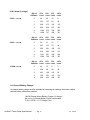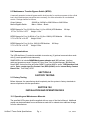
1
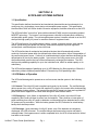
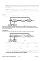
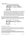
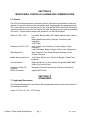
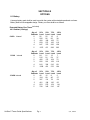
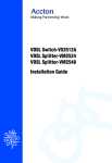
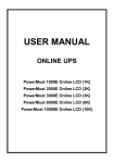
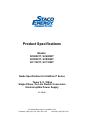
Product Specifications
Models:
SC60021T, SC60022T
SC80021T, SC80022T
SC11021T, SC11022T
Guide Specification for UniStar® P Series
Tower 6, 8, 10Kva
Single-Phase, On-Line Double Conversion
Uninterruptible Power Supply
11-19-10
301 Gaddis Blvd, Dayton, OH 45403, USA
Telephone: (866) 261-1191, (937) 253-1191
Facsimile: (937) 253-1723
SECTION 1.0
SCOPE AND SYSTEMS RATINGS
1.1 Specification
This specification defines the electrical and mechanical characteristics and requirements for a
continuous duty, single-phase, tower design uninterruptible power system. The specification
identifies 6Kva, 8Kva and 10Kva double conversion equipment, hereafter referred to as the UPS.
The UPS shall utilize "true on-line” pulse width modulated (PWM) inverter incorporating Isolated
MOSFET technology. The inverter is a microprocessor controlled, solid-state device within the
uninterruptible power system. The uninterruptible power system, hereafter referred to as the UPS,
shall provide high quality AC power for sensitive electronic equipment loads.
The UPS shall consist of a rectifier/charger, battery, inverter, protective devices, static transfer
switch, synchronizing and phase lock circuitry, and controls required to provide regulated,
uninterrupted, conditioned power to the critical load.
The UPS shall include all mechanical and electrical devices that will automatically provide
continuity of electrical power within the defined limits without interruption, failure or degradation of
the commercial power source. Continuity of conditioned electric power shall be maintained for the
defined period of time by the battery system. Upon return of the utility power source, the UPS
shall automatically assume the load, while simultaneously recharging the batteries. The UPS
shall provide paralleling capability for up to four individual units, either for added capacity or for
redundancy.
The UPS shall be capable of paralleling up to (4) UPS Modules for 40kva capacity or 30kva N+1
redundancy without additional parallel cabinet. Connection by RJ45 paralleling cable.
1.2 UPS Modes of Operation
The UPS shall be designed to operate as an on-line reverse transfer system in the following
modes:
1.2.1 Normal: The critical AC load is supplied continuously by the inverter. The rectifier/charger
derives power from a utility AC source and supplies DC power to the inverter while simultaneously
float charging a battery system. The inverter converts the DC power into clean and regulated AC
power that is then supplied to the critical load through the static transfer switch.
1.2.2 Emergency: Upon failure or degradation of the utility AC power, the critical AC load
supplied by the inverter will draw its power from the batteries. There shall be no interruption of
power switching from utility AC power to batteries or while switching from batteries back to utility
AC power upon its restoration. While the battery powers the UPS, indication for actual battery
backup time shall be provided.
1.2.3 Recharge: Upon restoration of utility AC power, even if the batteries are completely
discharged, the UPS will restart. The rectifier/charger shall assume the inverter and battery
recharge loads. If the bypass source is within acceptable limits, the UPS will retransfer the critical
load back to the inverter.
UniStar P Tower Guide Specifications
Pg. 2
6, 8, 10kVA
1.2.4 Bypass: When the inverter overload capacity is exceeded, the static transfer switch shall
perform a transfer of the load from the inverter to the bypass source with no interruption in power
to the critical load.
1.2.5 Maintenance Bypass: If for some reason the UPS has to be taken out of service for
maintenance or repair, the UPS shall be provided with an optional, external maintenance bypass
switch to enable a load transfer from the inverter to the bypass source with no interruption of
power to the critical load.
Utility Normal
The working principle of the UPS under Utility normal condition is illustrated as follows:
When Utility is normal, the AC source is rectified to DC, partially fed into the charger to charge
battery and partially fed into inverter. The inverter revert the DC to a cleaned and pure AC to supply
energy to the load connect.
Utility Absent
The working principle of the UPS under Utility abnormal condition is illustrated as follows:
1. When Utility is abnormal, the UPS will direct the battery energy automatically to the Inverter
without delay, and turn off the charger and AC/DC converter. The inverter revert DC to AC to
supply energy to the output load connected without interruption.
2. When Utility is back to Normal, the UPS will turn on the AC/DC converter, turn off DC/DC
converter and switch the charger to charging mode.
3. When Battery is low, alarm will beep continuously till battery is completely cut off. The battery
low protection of the UPS will cut off battery supply after a preset threshold to avoid the
battery from over-drain. The Battery Low LED’s will light up till the UPS is completely cut off.
The UPS will re-start automatically when Utility is available.
UniStar P Tower Guide Specifications
Pg. 3
6, 8, 10kVA
Overload Condition
The working principle of the UPS when overloading is illustrated as follows
1. Generally modern day electronics & IT equipment generate an inrush current when switching
on. The amount of inrush current varies from equipment to equipment, some can be as high
as 6 times its rated capacity while others produce negligible inrush. To prevent severe
damage to its Inverter cause by the inrush produce by the loads, the UPS is equipped with
electronics overload protection feature as standard. If the UPS loading is >105~120% of its
capacity, it will switch to bypass mode in 30 seconds to protect the Inverter. If overload
condition is eliminated by reducing the load to <105%, the UPS will switch back to Inverter
mode automatically. If the UPS is over 150% loading, it inverter will shutdown immediately.
Inverter Failure Output Load short circuit when supply via inverter
If output load is short circuited while supply via Inverter, the UPS will shutdown Inverter automatically
and stop supply to the loads. The Fault LED lights up and the alarm will beep continuously. The UPS
will not switch on automatically after short circuit condition is eliminated. The UPS has to be re-start
manually.
Fig. 5
Fig 5.5
Inverter/Internal Over temperature
If the UPS experiences internal over-temperature when Utility is normal, it will switch to bypass loop.
The UPS will switch back to inverter mode when the over-temperature situation is eliminated. If over
temperature occurs when Utility is abnormal, the alarm will beep continuously and the Fault LED will
light up. The UPS will cut off supply to the loads.
Current and Inverter Output Voltage Out of tolerance
If the UPS inverter delivers over-current and out-of-tolerance voltage to its outlets, the UPS is out of
order. The UPS will switch to bypass loop when Utility is normal. The Utility, Bypass and Fault LED’s
will light up. If these two fault conditions occur when Utility is abnormal, the UPS will cut off the supply to
its outlets and the Fault LED will light up.
UniStar P Tower Guide Specifications
Pg. 4
6, 8, 10kVA
1.3 System Ratings
1.3.1 Input
Ratings:
6kVA, 8kVA and 10kVA
Connection: 6kVA
Hardwire / Optional 6ft. Line Cord with L6-30P Plug
8kVA
Hardwire
10kVA
Hardwire
Voltage Range:
160 -280Vac
Frequency:
45 ~ 65 Hz
Phase/Wire:
Single, Line + Common + Ground
Power Factor:
Up to 0.99 at 100% Linear Load
Current THD:
<5% at 100% Linear Load
1.3.2 Output
Connection: 6kVA
Hardwire
8kVA
Hardwire
10kVA
Hardwire
Voltage:
21T Models
208/120 or 240/120
22T Models
208/220/230 or 240
Voltage Adjustment:
+/- 0%; +/- 1%; +/- 2%; +/- 3% For All Voltages
Voltage Regulation:
+/- 2%
Capacity:
6000VA/4200W, 8000VA/5600W, 10000VA/7000W
Parallel Capability:
Redundancy or Capacity – 4 Units Maximum
Rated Power Factor:
0.7 Lagging
Waveform:
Sine Wave, THD < 3% (no load to full load)
Frequency Stability:
+/- 0.2% (Free Running)
Frequency Regulation:
+/- 1 Hz
Transfer Time:
0ms/instantaneous
Crest Factor:
3:1
Efficiency (AC to AC Nominal):
91%
Efficiency (AC to AC ECO Mode):
Up to 97%
Leakage Current:
< 3mA @ Full Load
DC Start:
Yes
Cooling:
Load Dependant Variable Speed Fans
Full Load Heat Rejection BTU/hr:
6kva:1,472
8kva: 1,890
10kva: 2,363
UniStar P Tower Guide Specifications
Pg. 5
6, 8, 10kVA
1.3.3 Internal Battery
Internal battery shall be maintenance-free sealed type to minimize the need for servicing.
Battery shall be hot-swappable design, allowing users to replace the batteries without the
hazard of electrical shock or interruption to the connected load. The UPS shall continue to
supply power during such servicing, as applicable.
Battery Run Time @Full Load (Minutes):
6kVA
8
8kVA
7
10kVA
5
Type:
Sealed Lead Acid
Qty./Description:
6kVA
20 each 12V/7AH, 240Vdc
8kVA
20 each 12V/9AH, 240Vdc
10kVA
20 each 12V/9AH, 240Vdc
Hot – Swap Batteries:
Yes
Recharge Time:
6 and 8kVA
4 hours to 90%
10kVA
5 hours to 80%
SECTION 2.0
ENVIRONMENTAL
2.1 Environmental
Temperature:
Altitude:
Humidity:
Audible Noise:
0C – 40C
0 - 2,000 m up to 40° C. 3,000 m up to 35° C
90% RH Maximum, Non-Condensing
<50dbA (1 meter)
SECTION 3.0
GENERAL REQUIREMENTS
3.1 System Description
3.1.1 Rectifier/Charger
The rectifier section shall be capable of receiving utility input and rectifying it to produce Direct
Current (DC) power at levels sufficient enough to supply the load via the inverter, and recharge
the battery.
UniStar P Tower Guide Specifications
Pg. 6
6, 8, 10kVA
3.1.2 Inverter
The inverter section of the power converter module shall utilize MOSFET technology. This solidstate device that incorporates pulse width modulation (PWM) technology is capable of accepting
the output of the rectifier/charger or the battery system voltage and delivering AC power within
specified limits to the critical load bus. The inverter shall be microprocessor controlled and include
all necessary timing logic and control circuits.
3.1.3 Static Transfer Switch
An internally mounted static transfer switch and bypass circuit shall be provided as an integral
part of the UPS. The static switch shall be high speed power electronic devices rated to
conduct full load current continuously while on inverter or bypass power. The static switch
shall include all necessary logic circuitry for fully automatic frequency synchronization and
phase locking of the UPS inverter output to the bypass/reserve power source.
SECTION 4.0
WIRING AND CONNECTIONS
Wiring practices, materials and coding shall be in accordance with the requirements of the
National Electric Code, NFPA 70 and other applicable codes and standards
SECTION 5.0
MECHANICAL STANDARDS
5.1 Cabinet Description
The UPS unit, comprised of the rectifier/charger, inverter, static transfer switch shall be housed in
an enclosure offering indoor protection.
SC60021T SC60022T SC80021T SC80022T SC11021T SC11022T
Dimensions
(WxDxH)
11.4” x 25.4” x 29.5”
X
X
Dimensions
(WxDxH)
11.4” x 25.4” x 34.7”
Weight (lbs)
X
X
265
UniStar P Tower Guide Specifications
190
Pg. 7
320
X
X
203
340
223
6, 8, 10kVA
SECTION 6.0
MONITORING, CONTROLS, ALARMS AND COMMUNICATION
6.1 General
The UPS unit shall incorporate the necessary controls, instruments and indicators to allow the
operator to monitor the system status and performance, as well as take any appropriate action.
The communication port on the rear panel of the UPS shall be RS232 serial type, allowing for
computer connection to monitor the status of the UPS, and allow for the control and operation
of the UPS. Communication software will provide for use with MS Windows.
Status On LED + LCD
Line Mode, Backup Mode, ECO Mode, Bypass Supply, Battery
Low,
Battery Bad/Disconnected, Overload, Transferring with
interruption
& UPS Fault
Readings On LED + LCD
Input Voltage, Input Frequency, Output Voltage, Output
Frequency,
Load Percentage, Battery Voltage & Unit’s Inner Temperature
Self-Diagnostics
Upon Power-on, Front Panel Setting & Software Control,
24 Hour self check
Audible Alarms and Visual
Line Failure, Battery Low, Transfer to Bypass, System Fault
Conditions
Communications
RS232 Serial Port ( 2 slots available for optional SNMP/WEB,
USB or Dry Contact Card)
Emergency Power Off
customer
(EPO) Connection
Emergency Power Off shuts down UPS when activated by
supplied EPO Circuit
SECTION 7.0
STANDARDS
7.1 Applicable Documents
The UPS shall be designed in accordance with the applicable sections of the current revision of
the following documents.
Listing UL1778, c-UL; CE – FCC Class A
UniStar P Tower Guide Specifications
Pg. 8
6, 8, 10kVA
SECTION 8.0
OPTIONS
8.1 Battery
A storage battery pack shall be used to provide the system with extended operational run times.
Battery shall be hot-swappable design. Battery run times shall be as follows:
Extended Battery Run Times (minutes)
40 X Cabinet (2 strings)
6 kVA
8 kVA
Internal
Internal
10 kVA Internal
Qty. of
Cabinets
0
1
2
3
4
5
25%
Load
56
226
420
629
847
1073
50%
Load
22
95
180
273
370
471
75%
100%
Load Load
12
8
56
38
109
75
166
116
226
158
289
203
Qty. of
Cabinets
0
1
2
3
4
5
25%
Load
64
216
402
602
812
1028
50%
Load
21
91
172
261
354
451
75%
100%
Load Load
12
7
54
37
104
72
158
110
216
151
276
194
Qty. of
Cabinets
0
1
2
3
4
5
25%
Load
40
164
307
461
623
790
50%
Load
15
68
131
198
270
345
75%
Load
8
40
78
120
154
210
UniStar P Tower Guide Specifications
Pg. 9
100%
Load
5
27
54
83
114
147
6, 8, 10kVA
60 X Cabinet (3 strings)
Qty. of
Cabinets
25%
Load
0
56
22
12
8
1
321
137
82
56
2
629
273
166
116
3
959
420
257
180
4
1305
576
354
249
5
1660
737
454
321
6 kVA Internal
50% 75%
Load Load
Qty. of
Cabinets
25%
Load
0
64
21
12
7
1
307
131
78
54
2
602
261
158
110
3
919
402
246
172
4
1251
551
338
238
5
1594
706
435
307
8 kVA Internal
50% 75%
Load Load
100%
Load
Qty. of
Cabinets
25%
Load
0
40
15
8
5
1
234
98
58
40
2
461
198
120
83
3
706
307
187
130
4
963
422
258
181
10 kVA Internal
50% 75%
Load Load
100%
Load
100%
Load
8.2 External Battery Charger
An external battery charger shall be available for increasing the recharge time when multiple
external battery cabinets are installed.
1000W External Mount Battery Charger (1) charger
per every (2) External Battery Packs rcommended.
3.4”H x 6.6”W x 11.1”D Weight 7 lbs.
UniStar P Tower Guide Specifications
Pg. 10
6, 8, 10kVA
8.3 Maintenance Transfer Bypass Switch (MTBS)
A manually operated, external bypass switch shall provide for continuous power to the critical
load, when maintenance procedures are necessary, for either scheduled or unscheduled
events. Ratings shall be as follows:
Output Voltage:
Manual Bypass Switch:
208/208 or 240/240 or 208/120Vac or 240/120Vac
Make – Before – Break
MTBS Bypass for Two (2)-6KVA or One (1)-(8 or 10KVA) UPS Modules
3.7”H x 10.5”W x 9.5”D
Weight 11 lbs.
60 Amp
MTBS Bypass for Four (4)-6KVA or Two (2)-(8 or 10KVA) UPS Modules
3.7”H x 10.5”W x 16.4”D
Weight 20 lbs.
120 Amp
MTBS Bypass for Four (4)-(8 or 10KVA) UPS Modules
3.7”H x 10.5”W x 16.4”D
Weight 23 lbs.
200 Amp
8.4 Communications
The UPS shall have (2) card slots available to receive any (2) optional communication cards
with (2) cards operational simultaneously:
SNMP/WEB kit to include SNMP/Web browser adapter card, MIB software, interface
cable and operators manual. Support HP Open View, Sun SunNet Manager, IBM NetView,
Novell NMS, Accton AccView and other SNMP Compliant NMS's, and/or USB Interface Card
and/or Opto- coupler type Dry Contact Card, DB9 (AS/400) and/or Internal Relay Contact
Board Card, True Relay 10 Pin.
SECTION 9.0
FACTORY TESTING
9.1 Factory Testing
Before shipment, the manufacturer shall completely test the system to factory standards to
assure compliance with the specification.
SECTION 10.0
INSTALLATION AND OPERATION DATA
10.1 Operating and Maintenance Manuals
The specified UPS system shall be supplied with one copy of the User's Manual. Additional
copies may be downloaded from manufacturers web site or ordered at an additional charge
from the manufacturer.
UniStar P Tower Guide Specifications
Pg. 11
6, 8, 10kVA
SECTION 11.0
LIMITED WARRANTY
11.1 UPS and Battery Limited Warranty
The UPS parts with depot repair warranty shall be in effect for 24 months. The battery shall
provide for a one year warranty, prorated for a period of four years.
SECTION 12.0
QUALIFYING EXPERIENCE
12.1 Qualifying Experience
The manufacturer shall have a minimum of ten years experience in the design, manufacture, and
testing UPS systems. This specification outlines the minimum requirements for a UPS. Every
supplier shall provide a specification compliance statement with its proposal referencing each
section of this specification.
12.2 Approved Manufacturer
Staco Energy Products Company
301 Gaddis Blvd
Dayton, Ohio 45403
www.stacoenergy.com
(866) 216-1191 Fax (937) 253-1723
UniStar P Tower Guide Specifications
Pg. 12
6, 8, 10kVA