1
The FIRSTLINE EXTENDED
RUN TIME BATTERY CABINET
10 KVA
User’s Manual
301 Gaddis Boulevard • Dayton, Ohio 45403
U.S. Toll Free 866-261-1191
(937) 253-1191 • Fax: (937) 253-1723
Web site: www.stacoenergy.com
Form No.003-2359 Rev A
07/23/2010
FirstLine Extended Run Time Battery Cabinet 10 KVA
Form No. 003-2359 Rev A
FirstLine Extended Run Time Battery Cabinet 10 KVA
CONTENTS
Section 1 .............................................................................................................................. 1
Introduction ....................................................................................................................... 1
FirstLine Extended Run Time Battery Cabinet Part Number System................................ 1
Section 2 .............................................................................................................................. 2
Safety Warnings ............................................................................................................... 2
Section 3 .............................................................................................................................. 4
Battery Cabinet Setup....................................................................................................... 4
Inspecting The Equipment ................................................................................................ 4
Floor Loading .................................................................................................................... 4
Clearances ....................................................................................................................... 4
Unloading the Cabinet ...................................................................................................... 5
Placing The Cabinet ......................................................................................................... 7
Section 4 .............................................................................................................................. 8
Electrical Installation ......................................................................................................... 8
Wiring Preparation ............................................................................................................ 8
Connecting To The FirstLine Battery Cabinet ................................................................. 10
FirstLine UPS Part Number System ............................................................................... 13
Section 5 ............................................................................................................................ 14
Stopping the Rectifier in the UPS ................................................................................... 14
Section 6 ............................................................................................................................ 16
Battery Removal, Installation, and Service ..................................................................... 16
Maintenance ................................................................................................................... 17
Table 1 - Part Numbering System ........................................................................................ 1
Table 2 - Symbols ................................................................................................................ 2
Table 3 - Model Floor Loadings ............................................................................................ 4
Table 4 - FirstLine UPS Part Numbering System ............................................................... 13
Figure 1 - The FirstLine Extended Run Time Battery Cabinet .............................................. 1
Figure 2 - Extended Run Time Battery Cabinet .................................................................... 5
Figure 3 - Shipping Bracket .................................................................................................. 6
Figure 4 - Leveling foot being adjusted down to the floor ..................................................... 7
Figure 5 - Removing the Cabinet Front Panel ...................................................................... 9
Figure 6 - Batteries ............................................................................................................. 10
Figure 7 - Connectors......................................................................................................... 12
Figure 8 - UPS Connections............................................................................................... 13
Figure 9 - Battery Tray ....................................................................................................... 17
Figure 10 - Battery Wiring Schematic ................................................................................. 18
Form No. 003-2359 Rev A
FirstLine Extended Run Time Battery Cabinet 10 KVA
SECTION 1
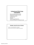
Introduction
The FirstLine extended run time battery cabinet is used in conjunction with the FirstLine
uninterruptible power supply (UPS) to prevent loss of valuable electronic information and
minimize equipment downtime. During brownouts, blackouts, and other power interruptions,
batteries provide emergency power to safeguard operation.
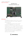
Figure 1 shows the FirstLine extended run time battery cabinet, which can be outfitted with
one or two strings of batteries. See Table 1 for part numbering system.
22.25 [565.0mm]
31.94 [811.2mm]
6.00 [152.4mm] MIN.
WALL CLEARANCE
FOR VENTILATION
VENTILATION HOLES
46.00 [1168.4mm]
IN
IN
BATTERY
POWER
OUT
OUT
CIRCUIT BREAKER CONTROL
FRONT ACCESS PANEL TO FUSES,
CIRCUIT BREAKER, AND BATTERIES.
LEVELING FEET
CUSTOMER POWER AND CONTROL
CONNECTIONS ON REAR
Figure 1 - The FirstLine Extended Run Time Battery Cabinet
FirstLine Extended Run Time Battery Cabinet Part Number System
Number of
DC Bus
Strings
Voltage
FLU-BAT-10-1-B
1
408 VDC
FLU-BAT-10-2-B
2
408 VDC
FLU-BAT-12-1-B
1
432 VDC
FLU-BAT-12-2-B
2
432 VDC
Note: -12 units are not part of UL Listing and are
used with the FLU-10S-22 UPS models only.
Part Number
Table 1 - Part Numbering System
Form No. 003-2359 Rev A
1
FirstLine Extended Run Time Battery Cabinet 10 KVA
SECTION 2
Safety Warnings
IMPORTANT SAFETY INSTRUCTIONS
SAVE THESE INSTRUCTIONS
This manual contains important instructions that you should follow during installation and
maintenance of the Battery Cabinet. Please read all instructions before operating the
equipment and save this manual for future reference.
READ AND FOLLOW ALL SAFETY INSTRUCTIONS
a.
b.
c.
d.
Do not use outdoors.
Do not route wiring across or near hot surfaces.
Do not install near gas or electric heaters.
Use caution when servicing batteries. Battery acid can cause burns to skin and
eyes. If acid is spilled on skin or in eyes, flush acid with fresh water and contact
a physician immediately.
e. Equipment should be installed where it will not readily be subjected to tampering
by unauthorized personnel.
f. The use of accessory equipment not recommended by the manufacturer may
cause an unsafe condition.
g. Do not use this equipment for other than intended use.
Table 2 - Symbols
Danger / Risk of Electric Shock
Caution
Risk of Explosion
Note
Ground Connection
Electrostatic Sensitive Device
Form No. 003-2359 Rev A
2
FirstLine Extended Run Time Battery Cabinet 10 KVA
DANGER
This Battery Cabinet contains LETHAL VOLTAGES. All repairs and service should
be performed by AUTHORIZED SERVICE PERSONNEL ONLY. There are NO
USER SERVICEABLE PARTS inside the Battery Cabinet.
WARNING
This Battery Cabinet contains its own energy source (batteries). Hazardous
voltage may be present even when the battery cabinet is not connected to a
power source.
To reduce the risk of fire or electric shock, install this battery cabinet in a
temperature and humidity controlled, indoor environment, free of conductive
contaminants. Do not operate near water or excessive humidity (95% maximum).
CAUTION
Batteries can present a risk of electrical shock or burn from high short circuit
current. Observe proper precautions. Servicing should be performed by qualified
service personnel knowledgeable of batteries and required precautions. Keep
unauthorized personnel away from batteries.
Risk of explosion if batteries are replaced by an incorrect type. Replace with same
type and rating only.
Proper disposal of batteries is required. Refer to your local codes for disposal
requirements.
Never dispose of batteries in a fire. Batteries may explode when exposed to flame
Form No. 003-2359 Rev A
3
FirstLine Extended Run Time Battery Cabinet 10 KVA
SECTION 3
Battery Cabinet Setup
This SECTION describes:
Equipment inspection
Floor loading and clearances
Removing and replacing the cabinet panels
Unloading the cabinet
Inspecting The Equipment
If any equipment has been damaged during shipment, keep the shipping and packing
materials for the carrier or place of purchase and file a claim for shipping damage. If you
discover damage after acceptance, file a claim for concealed damage.
To file a claim for shipping damage or concealed damage: 1) File with the carrier within 15
days of receipt of the equipment, 2) Send a copy of the damage claim within 15 days to
your service representative.
Floor Loading
When planning the installation, consider the battery cabinet weight for floor loading. The
strength of the installation surface must be adequate for point and distributed loading. The
approximate weights are shown in the following table.
Table 3 - Model Floor Loadings
STANDARD MODEL FLOOR LOADING
Battery Cabinet Model
FLU-BAT-10-1-B
FLU-BAT-10-2-B
Maximum Weight
757 Lbs (343 kg)
1289 Lbs (585 kg)
Point Loading
241 lb/in2 (17 kg/cm2)
410 lb/in2 (29 kg/cm2)
Clearances
The following clearances are recommended for the FirstLine Extended Run Time Battery
Cabinet.
From Front of Cabinet
From Back of Cabinet
From Left Side of Cabinet to UPS*
36” (91.4 cm) working space
6” (15.2 cm)
Minimum 24” (61 cm)
* The right side of the UPS needs 24” of clearance for service access if the UPS is a -42,
-44, or –I model. If the battery cabinet is placed on the left side of the UPS, no minimum
clearance is required.
Form No. 003-2359 Rev A
4
FirstLine Extended Run Time Battery Cabinet 10 KVA
Unloading the Cabinet
The following tools are required for unloading the cabinet:
Wrenches for 3/8” bolts
Forklift (For removing the cabinet from the truck and to separate the lower pallet
from the upper pallet and cabinet only. Once removed from the truck, remove the
cabinet from the pallet as stated below. DO NOT move to final location by forklift.)
CAUTION
The Battery Cabinet is heavy (see Table 3). Unloading the cabinet requires at least
two people to safely remove the cabinet from the pallets.
To remove the Battery Cabinet from the shipping pallets:
1.
2.
3.
4.
5.
6.
7.
Remove all banding, wrapping, and foam protectors.
With a forklift, lift the cabinet and upper pallet using the forklift channels (see figure
2) from the lower pallet by 1 to 2 inches. Slide the lower pallet completely away from
the cabinet. Lower the upper pallet and cabinet to the floor.
Remove the (12) 3/8” lag bolts securing the shipping brackets to the pallet and the
(4) 3/8” lag bolts securing the front guard board in place (see figure 2).
Remove the guard board and 3/4” wood spacers under each of the shipping
brackets.
Ensure that the four (4) leveling feet are raised so that they will not touch the floor
when the cabinet is placed on the floor.
Slowly roll the cabinet forward off the pallet.
Once the cabinet is fully off the pallet, slide the pallet completely away from the
cabinet.
Remove and discard
3/8" Lag bolts
(6) each side and (4)
in front
Shipping bracket - (1) this
side and opposite side
Remove 3/4" [19mm] spacer
Figure 2 - Extended Run Time Battery Cabinet
Form No. 003-2359 Rev A
5
FirstLine Extended Run Time Battery Cabinet 10 KVA
Shipping bracket
Figure 3 - Shipping Bracket
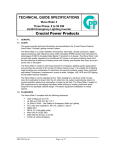
8.
9.
10.
Remove the (8) 3/8” bolts mounting the shipping brackets to the cabinet and remove
the brackets (see figure 3).
Roll the cabinet to the desired location
Do not move the cabinet to another location by forklift, as the cabinet is heavy
and may fall.
Form No. 003-2359 Rev A
6
FirstLine Extended Run Time Battery Cabinet 10 KVA
Placing The Cabinet
Once the cabinet has been rolled into position, remove the front panel to access the front
leveling feet by lifting the panel up and off the cabinet (see figure 5). Adjust the leveling feet
as shown in figure 4.
Lower the leveling foot
to the floor to secure
the cabinet in position
Figure 4 - Leveling foot being adjusted down to the floor
Form No. 003-2359 Rev A
7
FirstLine Extended Run Time Battery Cabinet 10 KVA
SECTION 4
Electrical Installation
WARNING
Only qualified service personnel (such as a licensed electrician) should perform the
Battery Cabinet installation and initial startup. Risk of electrical shock.
Wiring Preparation
To begin wiring the Battery Cabinet:
1.
Verify that the electrical connections to the installation site have been properly
installed.
2.
Wire the FirstLine UPS per the User’s Manual, form number 003-2258.
3.
Switch off utility power to the distribution point where the UPS is connected. Be
absolutely sure there is no power.
4.
Removing and replacing the front panel, see figure 5:
Lift the panel up and off the cabinet.
To replace the panel:
Lower the shoulder screws on the rear of the panel into the keyhole slots on
the cabinet.
Press the panel downward until the panel is firmly mounted in place.
5.
Switch the circuit breaker to the “Off” position.
6.
Remove the inner front cover by removing the (8) eight screws mounting it to the
enclosure.
Form No. 003-2359 Rev A
8
FirstLine Extended Run Time Battery Cabinet 10 KVA
CIRCUIT BREAKER
SHOULDER SCREW
Figure 5 - Removing the Cabinet Front Panel
Form No. 003-2359 Rev A
9
FirstLine Extended Run Time Battery Cabinet 10 KVA
Connecting To The FirstLine Battery Cabinet
To be performed by authorized service personnel:
1.
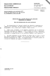
Inspect battery trays for signs of damage. Verify that all terminal connections are
sound. See figure 6.
2.
Use a voltmeter to verify that the battery string is above 408 VDC at the battery input
connector shown in figure 7.
Blue connectors
Red connectors
Black connectors
White connectors
Red connectors
Black connectors
Fuses
AUX.
SHUNT
CONTACT
TRIP
J5
J4
J3
C2
C1
K1
U1
R1
D1
R2
D3
D4
D2
C3
F1
IN
J1
OUT
J2
Figure 6 - Batteries
Form No. 003-2359 Rev A
10
FirstLine Extended Run Time Battery Cabinet 10 KVA
3.
Remove the top screw holding the left (input) connector cover on the rear panel and
loosen the bottom screw of this cover. Rotate the cover down. Replace the top
screw and tighten both screws as shown in figure 7.
4.
With the supplied 10 foot long power cable (Staco part number 817-0368), connect
from the left (input) battery power terminals on the rear of the cabinet to the similar
connector on the rear of the UPS. Ensure that the positive red connector of the
cable connects to the positive red connector on the rear of the cabinets.
See figure 7.
Never connect the positive (red) to the negative (black). Severe damage and
injury could result.
5.
Once the power cable is connected, place the connector clamping brackets over the
connectors as shown in figure 7 and lock in place with the #6-32 screws.
6.
With the supplied 10 foot long 6 pin Mini-DIN cable (Staco part number 273-0413),
connect from the left (input) circuit breaker control connector on the rear of the
cabinet to the similar connector on the rear of the UPS. See figure 8.
7.
Switch the circuit breaker to the “On” position.
8.
Replace the front panel of the battery cabinet.
CAUTION: If the circuit breaker trips, the internal batteries of the UPS are still
connected and providing power to the UPS.
9.
Additional battery cabinets connect to the “Battery Power Out” connector on the first
(or previous) battery cabinet instead of the UPS. Similarly, the “Circuit Breaker
Control Out” connection is made from the first (or previous) battery cabinet to the
“Circuit Breaker Control In” of the next (or following) cabinet.
Form No. 003-2359 Rev A
11
FirstLine Extended Run Time Battery Cabinet 10 KVA
Remove this screw
and replace after
cover is rotated
IN
IN
BATTERY
POWER
OUT
OUT
CIRCUIT BREAKER CONTROL
Loosen this screw
but do not remove
Battery Connector
IN
IN
BATTERY
POWER
OUT
OUT
CIRCUIT BREAKER CONTROL
Rotate cover down
and tighten screws.
If cable is removed
cover must be rotated
back over the opening
and locked in place
with screws.
Circuit Breaker control connectors
IN
IN
BATTERY
POWER
OUT
OUT
CIRCUIT BREAKER CONTROL
Power Cable
REAR VIEW
LEFT SIDE VIEW
Figure 7 - Connectors
Form No. 003-2359 Rev A
12
FirstLine Extended Run Time Battery Cabinet 10 KVA
The following FirstLine UPS models are to be used with this battery cabinet:
FirstLine UPS Part Number System
Table 4 - FirstLine UPS Part Numbering System
Full Part Number
kVA
Input Voltage
Output
Voltage
Basic Part
No.
10
480
480
208Y/120
208Y/120
220Y/127
220Y/127
208Y/120
480Y/277
208Y/120
208Y/120
220Y/127
220Y/127
FLU-10S-42
FLU-10S-44
FLU-10S-20
FLU-10S-20
FLU-10S-22
FLU-10S-22
Battery
Option
-1
-1
-2
-1
-1
-2
Other
Options
-I
-I
-I
Battery Option
-1 =
-2 =
-0 =
1 string
2 string
Without Batteries
Other Options
Isolation Transformer
Suffix
-I
Notes
Isolation transformer required for use with delta (3wire) input. Standard is K20 rated.
220V Models are not listed to UL, CUL, or CSA.
1
2
3
4
1
2
3
4
5
6
7
8
9 10
1
2
3
4
5
6
7
8
9 10 11 12 13 14 15
1
2
3
4
5
6
7
8
9 10
FUS E
External battery
circuit breaker
control connector
UPS REAR VIEW
Figure 8 - UPS Connections
Form No. 003-2359 Rev A
13
FirstLine Extended Run Time Battery Cabinet 10 KVA
SECTION 5
Special Considerations for Connecting Batteries to the FirstLine UPS, including
Extended Run Time Battery Cabinets
It is never safe to work within either the UPS or the extended battery cabinet while the UPS
is powered. The batteries produce a lethal voltage whether or not the UPS is powered or
running. Always work with extreme caution. No service work should be performed unless
the personnel are properly trained and appropriate tools and equipment are available.
All batteries must be connected to the UPS prior to starting the rectifier. The rectifier runs
whenever the UPS is on. If a battery is disconnected while the rectifier is running (for
example, if the circuit breaker on an extended battery cabinet is opened while the UPS is
running), it must not be closed without first stopping the rectifier. Connecting a battery
while the rectifier is running will cause equipment damage that is not covered by the
equipment warranty. See the procedure, below, for stopping the rectifier.
Before connecting the cables between the UPS and the Extended Run Time Battery
Cabinet, the UPS must be powered down. On the Extended Run Time Battery Cabinet, the
front outer panel must be removed and the circuit breaker placed in the “Off” position. See
Section 4, “Connecting to the FirstLine Battery Cabinet” to connect the cables.
Stopping the Rectifier in the UPS
Before connecting any batteries to the UPS, the rectifier must be stopped. The rectifier is
stopped whenever the UPS is OFF. All breakers should be closed when the UPS is started.
Generally, the only reason to open any of the battery disconnect devices is to perform
service, which requires that the UPS be turned off. It is best to close the disconnect devices
before starting the UPS and leave them closed during operation. In the event of an
emergency condition that requires opening a disconnect device, it will be necessary to stop
the rectifier in order to restore the system to normal configuration.
The simplest way to stop the rectifier is to turn off the UPS by pressing the power ("linecircle") button on the front panel. This will remove power from the load. Once the battery
breaker(s) has (have) been closed, the UPS can be restarted by pressing the power button.
If the UPS is connected to the load using a Maintenance Bypass Switch (MBS), the load
can be maintained when the UPS is turned OFF.
To transfer to MBS:
1.
Verify that the bypass source is available (Bypass lamp on UPS mimic display is
green).
2.
Perform a manual transfer to bypass mode on the UPS by pressing and holding the
ESC key while simultaneously pressing the UP-ARROW key.
Form No. 003-2359 Rev A
14
FirstLine Extended Run Time Battery Cabinet 10 KVA
3.
Verify that the UPS output is ON BYPASS by observing that the lamp associated
with the bypass line at the static switch block on the mimic display is green and that
the lamp associated with the inverter is not lit.
4.
Operate the MBS to put it in bypass mode.
It is now safe to turn off the UPS and close the battery breaker(s). Restart the UPS. To
transfer back to normal mode:
1.
Verify that the UPS is still ON BYPASS by observing the mimic display. If not,
perform a manual transfer to bypass as described, above.
2.
Operate the MBS to put it in normal mode.
3.
Enable automatic transfer by pressing and holding the ESC key while
simultaneously pressing the DOWN-ARROW key. After a few seconds, the mimic
display should show that the static switch has transferred the load to inverter.
CAUTION: The battery cabinet circuit breaker must be closed before starting the
UPS. Switch the circuit breaker “On” while the UPS is operating can cause
equipment damage that is not covered by the equipment warranty.
Form No. 003-2359 Rev A
15
FirstLine Extended Run Time Battery Cabinet 10 KVA
SECTION 6
Battery Removal, Installation, and Service
The batteries must only be serviced by authorized service personnel.
Before any battery service is attempted, the batteries must be disconnected by unplugging
the cables to the battery trays. Before removing the cables, the connections should be
marked in a way that no confusion will exist when it is time to reconnect the cables (see
Figures 6 and 10). The batteries are mounted in slide out trays that permit access to the
battery to battery connections when the trays are withdrawn from the cabinet.
If batteries are being replaced, only use the same manufacturer and battery type and rating
as the battery removed.
It is very important that only one tray at a time be extended from the cabinet. If more than
one tray is extended, the cabinet can become unstable and topple over.
After each tray is installed or serviced, it must be fully inserted and secured using the
supplied threaded fasteners before attempting to install or service another tray.
If the trays are to be removed, always remove the highest tray first. The battery trays are
very heavy and it will be necessary to use a lifting device to support the trays as they are
removed. When the trays are to be reinstalled, use the procedure in the following
paragraph.
The battery trays are very heavy and it will be necessary to use a lifting device to support
the trays as they are installed. Do not take away the external support until the extension
limit tabs on the upper sides of the battery tray are inserted past the notches on the upper
edge of the battery shelf (see figure 9). Always install the lowest battery tray first. After it is
inserted fully into the support shelf, secure the tray with the supplied threaded fasteners.
After all of the trays are reinstalled and secured, reconnect the cables using the markings
as a guide.
WARNING
Never connect the two cables from a battery tray or from a battery string (two trays)
together as severe damage will occur, resulting in fire and/or injury. Battery connections
should only be made by a person wearing eye and hand protection. It is advised that eye
wash be available. If there are any doubts about the proper connections, do not proceed.
Form No. 003-2359 Rev A
16
FirstLine Extended Run Time Battery Cabinet 10 KVA
Extension limit tab
Notch
Battery tray
Tray mounting screw
Battery shelf
Cutaway side view of battery tray
batteries not shown for clarity
Figure 9 - Battery Tray
Maintenance
The FirstLine Extended Run Time Battery Cabinet is designed to be virtually user
maintenance free, requiring only the occasional wipe with a damp cloth or non-abrasive
cleaner.
Spare kits are available for the FirstLine Battery Cabinet series, please contact Staco
Energy Products Co. service center for details.
For maximum availability of the UPS, the batteries should be replaced as part of a
comprehensive preventive maintenance program:
REPLACEMENT BATTERY
Manufacturer
Cat. Number Quantity Required
China Storage Battery
HRL1280W
34 per string1
China Storage Battery
HR1290W
34 Per string1
REPLACEMENT BATTERY
Suitable for computer-room applications
Manufacturer
Cat. Number Quantity Required
China Storage Battery
HR1280WFR 34 Per string1
China Storage Battery
HR1290WFR 34 Per string1
RECOMMENDED REPLACEMENT INTERVALS
Batteries
2 to 5 years2
Note: Batteries suitable for computer rooms are good for all applications.
1
FLU-BAT-12 Battery cabinet contains 36 batteries per string. Note: -12 units are not part of UL listing.
2
Battery life is highly dependent on the ambient temperature and the number and depth of discharge cycles.
A discharged battery should be recharged as soon as possible. If the battery is left in a discharged state,
irreversible sulfation occurs, reducing the capacity (run-time) of the battery.
Form No. 003-2359 Rev A
17
Form No. 003-2359 Rev A
F2
F1
J3
J1
J2
J5
TRAY 1
TRAY 2
INPUT
BATTERY
CONNECTORS
+
GND
F2
F1
BLACK CONNECTORS
CIRCUIT BREAKER
CONTROL
IN
BATTERY BREAKER
INTERFACE BOARD
CIRCUIT BREAKER
J4
FUSEHOLDER AND
30 AMP, 600 VDC FUSES
TRAY 1
TRAY 2
TRAY 3
TRAY 4
-1-B SCHEMATIC
CIRCUIT BREAKER
CIRCUIT BREAKER
CONTROL
OUT
BATTERY BREAKER
INTERFACE BOARD
OUTPUT
BATTERY
CONNECTORS
+
GND
RED CONNECTORS
WHITE CONNECTORS
CIRCUIT BREAKER
CONTROL
IN
INPUT
BATTERY
CONNECTORS
+
GND
F2
F1
BLACK CONNECTORS
TRAY 1
BLACK CONNECTORS
TRAY 2
TRAY 3
TRAY 4
-2-B SCHEMATIC
CIRCUIT BREAKER
CIRCUIT BREAKER
CONTROL
OUT
BATTERY BREAKER
INTERFACE BOARD
OUTPUT
BATTERY
CONNECTORS
+
GND
RED CONNECTORS
WHITE CONNECTORS
RED CONNECTORS
BLUE CONNECTORS
FirstLine Extended Run Time Battery Cabinet 10 KVA
Figure 10 - Battery Wiring Schematic
18
FirstLine Extended Run Time Battery Cabinet 10 KVA
Form No. 003-2359 Rev A
19