1
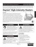
INSTALLATION AND OPERATION INSTRUCTIONS OWNER / INSTALLER: For your safety this manual must be carefully and thoroughly read and understood before installing, operating or servicing this heater. INFRARED RADIANT CERAMIC HEATER DK SERIES !INSTALLER:This manual is the property of the owner. Please present this manual to the owner when you leave the job site. SWARNING: Improper installation, adjustment, alteration, service, or maintenance can cause property damage, injury or death. Read the installation, operation and maintenance instructions thoroughly before installing or servicing this equipment. !IMPORTANT: SAVE THIS MANUAL FOR FUTURE REFERENCE. SPACE-RAY® Post Office Box 36485 (28236) 305 Doggett Street (28203) Charlotte, North Carolina Phone (704) 372-3485 Fax (704) 332-5843 www.spaceray.com email: [email protected] Form #43219010 June 08 ! WHAT TO DO IF YOU SMELL GAS: ! ! ! ! DO NOT try to light any appliance. Extinguish any open flame. Open windows. DO NOT touch any electrical switch. DO NOT use any telephone in your building. Immediately call your gas supplier from a neighbor’s telephone. Follow the gas supplier's instructions. If you cannot reach your gas supplier, call the Fire Department. SWARNING: NOT FOR RESIDENTIAL USE. SWARNING: ♦ Installation and service must be performed by a qualified installer, service agency or the gas supplier. ♦ If the information in these instructions is not followed exactly, a fire or explosion may result causing property damage, personal injury or death. ♦ DO NOT store or use gasoline or other flammable vapors and liquids in the vicinity of this or any other appliance. TABLE OF CONTENTS SECTION 1) 2) 3) 4) 5) 6) 7) 8) DESCRIPTION PAGE SECTION GENERAL INFORMATION ..................................................................... 1 MINIMUM CLEARANCES TO COMBUSTIBLES ........................ 3 HANGING............................................................................... 3 DK SERIES SPECIFICATIONS............................................................. 4 DK SERIES DIMENSIONS ..................................................................... 4 GAS CONNECTIONS AND REGULATION ..................................... 5 PRESSURE TEST GAUGE CONNECTION ........................... 6 ELECTRICAL CONNECTIONS .............................................................. 6 9) 10) 11) 12) 13) 14) 15) 16) 17) DESCRIPTION PAGE VENTILATION ........................................................................................................ 7 LIGHTING AND SHUTDOWN INSTRUCTIONS .................................. 8 CLEANING AND ANNUAL MAINTENANCE ......................................... 8 BURNER OPERATION/TROUBLESHOOTING ................................... 8 OPTIONAL PARABOLIC REFLECTOR EXTENSION..................... 11 OPTIONAL PROTECTIVE REVERB SCREEN.................................... 11 REPLACING PARTS ....................................................................................... 11 INSTALLATION DATA ................................................................................... 11 REPLACEMENT PARTS GUIDE 12 This heater complies with Z83.19 (current standard) and CSA 2.35. Copies of the National Fuel Gas Code (ANSI Z223.1-latest edition) are available from the CSA at 8501 East Pleasant Valley Road, Cleveland, Ohio 44131 or 55 Scarsdale Road, Don Mills, Ontario M3B 2R3. All NFPA codes are available from the National Fire Protection Association, Batterymarch Park, Quincy, Massachusetts 02269. 1) GENERAL INFORMATION This heater is a self-contained infrared radiant ceramic heater for use in locations where flammable gases or vapors are not generally present (as defined by OSHA acceptable limits) and is intended for the heating of nonresidential spaces. SAFETY REQUIREMENTS ! The heater area must be kept clear and free from combustible materials, gasoline and other flammable vapors and liquids. ! This heater is designed for use with one type of gas (LPG or Natural). Make sure that the type of gas to be supplied to this heater matches that shown on the heater rating plate. ! DO NOT install this heater directly onto an LPG container or propane cylinder without directions from your propane 1 Form #43219010 June 08 company. LPG containers (propane cylinders) must not be stored indoors or in the vicinity of any gas-burning appliance. ! Children and adults should be alerted to the hazards of high surface temperatures and should stay away to avoid burns or clothing ignition. ! Clothing or other flammable materials should not be hung from the heater or placed on or near the heater. ! Young children should be carefully supervised when they are in the same space as the heater. ! NEVER attempt to service the heater while it is plugged in, operating or hot. Any guard or other protective device removed for servicing a heater must be replaced prior to operating the heater. ! Installation and repair should be done by a qualified service person. The heater should be inspected before use and at least annually by a qualified service person. More frequent cleaning may be required as necessary. It is imperative that the control compartment, air passageways and burner of the heater be kept clean. ! Heaters intended for use at high altitude should be de-rated for optimum performance. Check the heater rating plate to be sure that the heater has been de-rated. (The statement “This appliance equipped for high altitude elevation 2,000 to 4,500 feet” should appear on the rating plate if it has been de-rated at the factory.) If the heater has not been de-rated, contact the factory for the necessary high-altitude conversion kit(s). INSTALLATION REQUIREMENTS Installation of this heater must be in accordance with all applicable codes shown in the instructions and/or the local codes and authorities having jurisdiction. In Canada, the installation must conform to current CAN/CGA-B149.1/2 Installation Code in the absence of local codes. Heaters shall be installed by a licensed contractor or licensed installer. Clearances to combustibles as outlined in this manual should always be observed. In areas used for storage of combustible materials where they may be stacked below the heater, NFPA54 requires that the installer must post signs that will “specify the maximum permissible stacking height to maintain the required clearances from the heater to combustibles.” Every heater shall be located with respect to building construction and other equipment so as to permit access to the heater. Each installer shall use quality installation practices when locating the heater and must give consideration to clearances to combustible materials, vehicles parked below, lights, overhead doors, storage areas with stacked materials, sprinkler heads, gas and electrical lines, and any other possible obstructions or hazards. Consideration also must be given to service accessibility. The heater, when installed in aircraft hangars and public garages, must be installed in accordance with ANSI/NFPA 409-latest edition (Standard for Aircraft Hangars), ANSI/NFPA 88a-latest edition (Standard for Parking Structures), and ANSI/NFPA 88blatest edition (Standard for Repair Garages) with the following clearances: a. At least 10 feet above the upper surfaces of wings or engine enclosures of the highest aircraft that may be housed in the hangar and at least 8 feet above the floor in shops, offices, and other sections of hangars communicating with aircraft storage or service areas. b. At least 8 feet above the floor in public garages. SWARNING: Minimum clearances marked on the heater must be maintained from vehicles parked below the heater. (FOR CANADA ONLY) a. b. Installation of this appliance is to be in accordance with latest edition of CAN 1-B149.1 (Installation Code for Natural Gas Burning Appliances and Equipment), and/or CAN B149.2 (Installation Code for Propane Gas Burning Appliances and Equipment). For installation in public garages or aircraft hangars, the minimum clearances from the bottom of the infrared heater to the upper surface of the highest aircraft or vehicle shall be 50 percent greater than the certified minimum clearance, but the clearance shall not be less than 8 feet. Although these heaters may be used in many applications other than space heating (e.g., process heating), Gas-Fired Products, Inc. will not recognize the warranty for any use other than space heating. This heater is for Indoor Installation only and can be used in Unvented mode. The term Unvented actually means Indirect Vented. While the products of combustion are expelled into the building, national codes require ventilation in the building to dilute these products of combustion. This ventilation may be provided by gravity or mechanical means. This heater is not an explosion proof heater. Where the possibility of exposure to volatile and low flash point materials exists, it could result in property damage or death. This heater must not be installed in a spray booth where the heater can operate during the spraying process. Consult your local fire marshal or insurance company. SWARNING: Certain materials or objects, when stored under the heater, will be subjected to radiant heat and could be seriously damaged. Observe the Minimum Clearances to Combustibles listed in the manual and on the heater at all times. ! A T T E N T I O N: S A V E T H I S M A N U A L F O R F U T U R E R E F E R E N C E . Form #43219010 June 08 2 2) MINIMUM CLEARANCES TO COMBUSTIBLES Minimum clearances shall be measured from the outer surfaces as shown below: ! IMPORTANT: WHEN ANGLE MOUNTING, THE VALVE AND MANIFOLD SIDE MUST BE DOWN. Gas Valve CEILING Gas Manifold Assembly FRONT A SIDE REAR SIDE BELOW MINIMUM CLEARANCES TO COMBUSTIBLES Mounted Horizontally BELOW MODEL SIDES CEILING w/Standard Reflector Mounted at 35º Angle BELOW FRONT w/Reflector Extension w/Standard Reflector w/Reflector Extension w/Standard Reflector w/Reflector Extension A REAR Angle Mounting (degree) DK30 DK33 DK35 DK40 30” 36” 72” 100” 72” 100” 36” 50” 30” 0º min 35º max DK60 DK66 DK70 DK80 48” 48” 98” 137” 98” 137” 48” 68” 36” 0º min 35º max 48” 64” 128” 180” 128” 180” 60” 84” 48” 0º min 35º max 60” 64” 136” 190” 136” 190” 64” 90” 48” 10º min 35º max DK100 DK120 DK132 DK140 DK160 NOTE: The clearances specified above must be maintained to combustibles and other materials that may be damaged by temperatures 90ºF above ambient temperature. It is the installer’s responsibility to ensure that building materials with a low heat tolerance which may degrade at lower temperatures are protected to prevent degradation. Clearances to combustibles are posted on the reflector near the control end of the heater. In locations used for storage of combustible materials where they may be stacked below the heater, NFPA 54 requires that the installer must post signs that will “specify the maximum permissible stacking height to maintain the required clearances from the heater to combustibles.” Space-Ray recommends posting these signs adjacent to the heater thermostat or other suitable location that will provide enhanced visibility. 3) HANGING The heater can be mounted with the reflector horizontal or angled up to 35º from horizontal. When the heater is to be angle mounted, make sure the gas manifold assembly is on the lower side of the heater. Coil chains (No. 2 or larger) or rigid supports may be used to mount the heater, which must be suspended from a permanent structure with adequate load capacity. The gas manifold assembly tube must be level, and for angled mounting, it must be at the LOWER end of the heater. All “S” hooks and eyebolts must be manually crimped closed by the installer. 3 Form #43219010 June 08 4) DK SERIES SPECIFICATIONS MODEL NO. BTU/HR INPUT DK30-N5B DK35-N5B DK40-N5B DK60-N5B DK70-N5B DK80-N5B DK100-N5B DK120-N5B DK140-N5B DK160-N5B DK33-L5B DK66-L5B DK100-L5B DK132-L5B NUMBER OF BURNERS Natural Gas Propane Gas SHIPPING WEIGHT MINIMUM MOUNTING HEIGHT (feet) 1 1 1 2 2 2 3 3 4 4 1 2 3 4 3/32” #41 #38 3/32” #41 #38 #41 #38 #41 #38 n/a n/a n/a n/a n/a n/a n/a n/a n/a n/a n/a n/a n/a n/a #52 #52 #52 #52 30 lbs. 30 lbs. 30 lbs. 35 lbs. 35 lbs. 35 lbs. 48 lbs. 48 lbs. 58 lbs. 58 lbs. 30 lbs. 35 lbs. 48 lbs. 58 lbs. 11 12 12 13 13 14 15 16 17 18 11 13 15 17 33,000 35,000 40,000 65,000 70,000 80,000 100,000 120,000 140,000 160,000 33,000 66,000 99,000 132,000 ORIFICE SIZE7 Gas Type: N = Natural L = Propane 7 One Orifice Per Burner GAS-PIPE CONNECTION: MODEL SUFFIX Ignition System: 5 = Direct Spark (115 Volt / 0.40 Amp / 60 Hz) 1/2” NPT (Female) *MOUNT HEATERS AS HIGH AS POSSIBLE. Minimums are shown as a guideline for human comfort and uniform energy distribution for complete building heating applications. Consult your Space-Ray representative for the particulars of your installation requirements. 5) DK SERIES DIMENSIONS 15-3/4 (40cm) 9 (23cm) Hanging Dimension 26-1/2 (67cm) 21/5/8 (55cm) 27-1/2 (70cm) 14-7/8 (38cm) Hanging Dimension 20-3/4 (53cm) Hanging Dimension 26-1/2 (67cm) 12 (30cm) Hanging Dimension (Typical all Models) 1-BURNER UNIT 26/1/2 (67cm) 2-BURNER UNIT 3-BURNER UNIT 33-3/8 (85cm) 26-5/8 (68cm) Hanging Dimension Gas Manifold Assembly Ignition Control Assembly 3/8 (1cm) Diameter Hole for Hanging (Typical 4 Places) 26-1/2 (67cm) 7-3/4 (20cm) Form #43219010 June 08 4 26-1/2 (67cm) 4-BURNER UNIT TYPICAL SIDE VIEW Reflector Assembly 6) 1. 2. 3. 4. GAS CONNECTIONS AND REGULATION Connect to the supply tank or manifold in accordance with the latest edition of National Fuel Gas Code (ANSI Z223.1), and local building codes. Authorities having jurisdiction should be consulted before the installation is made. All gas supply lines must be located in accordance with the required clearances to combustibles below the heater as listed on the nameplate of the heater. Pipe joint compounds must be resistant to the action of liquefied petroleum gases. Where local codes do not prohibit, a CSA or U.L. approved flexible connector (minimum 5/8” I.D.) is recommended between the rigid piping and the heater. A union and an approved shut-off valve should be installed before the control valve inlet. The shut-off valve should be installed within 6 feet of the union. *Manual Gas Shut Off Valve Gas Pressure = 2 PSIG *Second Stage Regulator with Vent Leak Limiter to reduce the Supply Pressure below 14 W.C. Gas Supply Piping Alternate Supply Location * Approved Flexible Connector Sediment Trap (Drip Leg) 12 (30cm) END VIEW SIDE VIEW * Available as Accessories 5. 6. 7. TYPICAL GAS CONNECTIONS This appliance is equipped with a snap-opening, combination gas valve. The maximum supply Certified connections are recommended to be pressure to the appliance is 14” W.C. or 1/2 P.S.I. If installed as shown, in one plane, and without the line pressure is more than the maximum supply sharp bends, kinks or twists. The gas take off pressure, then use a line regulator as indicated in the from the drop line must be parallel to the following illustration, or a line regulator which burner gas inlet connection. corresponds to the supply pressure. If a second stage regulator is used and gas seeps If the maximum supply pressure is less than ½ through it, the redundant combination gas valve is psig, a second stage regulator is not required. designed to lock out. Pressure build-up in the supply lines prior to the heater must be released before proper heater operation. After all gas connections have been made, make sure the heater and all gas outlets are turned off before the main gas supply is turned on. Turn the gas pressure on and check for leaks. To check for leaks, apply a soapsuds solution to all connections and joints or check by one of the methods listed in Appendix D of the National Fuel Gas Code, ANSI Z223.1(latest edition). ! DO NOT USE AN OPEN FLAME OF ANY KIND TO TEST FOR LEAKS. 5 Form #43219010 June 08 7) INSTRUCTIONS FOR PRESSURE TEST GAUGE CONNECTION Supply Pressure 1. The installer will provide a 1/8” N.P.T. plugged tapping, accessible for test gauge connection immediately upstream of the gas supply connection to the heater. Manifold Pressure: 1 Turn the gas valve to the “OFF” position. Remove the 1/8” plug from the combination gas valve at the outlet pressure tap and connect the 1/8” nipple to the tapped hole. Connect gauge to nipple. Turn on the gas supply. 2. With the main burner operating, check the burner manifold pressure using a water manometer. The combination gas valve is factory set and should not be adjusted. If adjustment is required, remove the cover screw. Using a small screwdriver, turn the adjustment screw clockwise 3 to increase, or counter-clockwise 4 to decrease the gas pressure to burner. Replace the cover screw. 3. Gauges that measure in pounds per square inch are not accurate enough to measure or set the manifold pressure. Use a water manometer or a gauge calibrated in inches of water column. All measurements MUST BE made when this heater and all other gas burning equipment that is connected to the gas supply system are operating at maximum capacity. GAS PRESSURE TABLE GAS TYPE MANIFOLD PRESSURE DK (30, 35, 40, 60, 70, 80, 100 120, 140 & 160) Natural DK (33, 66, 100 & 132) Propane HEATER MODEL SUPPLY PRESSURE 7 Minimum Maximum 6” W.C. 7” W.C. 14” W.C. 10” W.C. 11” W.C. 14” W.C. 7 Minimum permissible gas supply pressure for purpose of input adjustment. CAUTION Never jumper these terminals. This shorts out valve coil and may burn out heat anticipator in thermostat. Pressure Regulator Adjustment (under cap screw) Wiring Terminals (2) 1/8 NPT Inlet Pressure Tap with 3/16 Hex Allen Wrench Plug Ground Terminals (2) OUTLET INLET GAS CONTROL VALVE (#VR8205A) 8) 1. 2. 3. 4. 5. Gas Control Knob 1/8NPT Outlet Pressure Tap with 3/16 ELECTRICAL CONNECTIONS All electric wiring shall conform to the latest edition of the National Electrical code (ANSI/NFPA No. 70), or the code legally authorized in the locality where the installation is made. The unit must be electrically grounded in accordance with the National Electrical code (ANSI/NFPA No. 70-latest edition). In Canada, refer to current standard C22.1 Canadian Electrical Code Part 1. The wiring providing power to the heater shall be connected to a permanently live electrical circuit, one that is not controlled by a light switch. The power supply to the unit should be protected with a fused disconnect switch or circuit breaker. A service switch, as required by local codes, shall be located in the vicinity of the heater (check local codes for allowable distances) and should be identified as Heater Service Switch. All electrical wiring must be located in accordance with the required Clearances to Combustibles below the heater as listed on the nameplate on the heater. When connecting the supply circuit to the heater, wiring material having a minimum size of 14 AWG and a temperature rating of at least 90˚C shall be used. Form #43219010 June 08 6 CONNECTION WIRING DIAGRAM For Direct Spark Ignition System with Fenwal Module Red Line Voltage Thermostat TH Ignition Module No. 2460D 24VAC 120 VAC Factory Wiring Field Wiring Transformer V1 Blue V2 FC+ FC- Blue GND MV MV Gas Valve Wht White Spark Electrode Notes: Ignition Cable 1. If any ot the original wire as supplied with the appliance must be replaced, it must be replaced with wiring having a temperature rating of at least 105deg. C (18Ga. CSA-600V-Type TEW). 2. When connecting the supply circuit to the heater, wiring material having a minimum size of 14 AWG and a temperature rating of at least 90deg. C shall be used. TYPICAL THERMOSTAT WIRING Single Heater Per Thermostat Multiple Heaters Per Thermostat Ground 120V Continue to additional heaters Neutral Hot Ground Neutral Hot 120V Continue to additional heaters Thermostat Thermostat Service Switch Service Switch Service Switch Heater Heater 9) Heater VENTILATION This heater requires ventilation in the building to dilute the products of combustion and provide fresh air for efficient combustion. Power ventilation is recommended and the minimum vent flow required is as follows: DK30, DK33, DK35 DK40 DK60, DK66, DK70 DK80 128 cfm 150 cfm 256 cfm 300 cfm DK100 DK120 DK132, DK140 DK160 384 cfm 448 cfm 512 cfm 600 cfm If gravity ventilation is used, the required square feet of inlet and outlet vent area (depending on height and temperature difference) is as follows: DK30, DK33, DK35 DK40 DK60, DK66, DK70 DK80 0.49 s/f 0.57 s/f 0.98 s/f 0.98 s/f DK100 DK120 DK132, DK140 DK160 1.48 s/f 1.72 s/f 1.97 s/f 2.30 s/f The General Ventilation Rules outlined in ASHRAE GUIDE AND DATA BOOK should be observed when locating vents. Exhaust vents must be located at the highest point above and in the vicinity of the heaters and the inlet vents must be located below the level of the heaters. 7 Form #43219010 June 08 10) LIGHTING AND SHUTDOWN INSTRUCTIONS DIRECT SPARK IGNITION SYSTEM (Ignition Suffix “5”) 1. 2. 3. 4. Turn on the gas supply. Set the thermostat to call for heat. Ignition should occur immediately. If ignition fails, the unit will spark for approximately 21 seconds and go into safety lockout. Turn the thermostat (or power) off for 60 seconds to take the system out of lockout. 5. If the heater does not light, shut off the gas completely for 5 minutes before attempting to relight. 6. SCAUTION: The heater must be grounded. Poor grounding will give nuisance lockouts, particularly during momentary power interruptions. 7. To shut down the heater, turn off the gas and the electrical supply. NOTE: The lighting and shutdown instructions are also shown on the permanent nameplate attached to the heater. 11) CLEANING AND ANNUAL MAINTENANCE This heater consists of multiple individual atmospheric burners. Due to the variation in tile porosity, there could be color variations between the burners. This is natural and should not be a cause for concern during the initial startup. This heater must be cleaned and serviced at least once before the start of each heating season or at any time the infrared emitter shows signs of collecting any foreign material on its surface or in the ports, or when anything obstructs the venturi or the screen. Maximum heating efficiency and clean combustion will be maintained by keeping the emitter and burner clean. To clean the heater, follow these instructions: 1. Turn off all electrical and gas supply to the heater. 2. Clean the reflector. 3. Remove the main burner orifice and clean it thoroughly. 4. Check the venturi opening to be sure it is clean. If there is any evidence of dirt accumulation in the venturi, remove it. 12) BURNER OPERATION/TROUBLESHOOTING A) IGNITION MODULE DIAGNOSTICS The LED located on the ignition module (see Figure) will flash ON for ¼ second, then OFF for ¼ second during a fault condition. The pause between fault codes is 3 seconds. LED Indication Steady On 2 Flashes 3 Flashes Error Mode Internal Control Failure Flame Sense Fault Ignition Lockout B) FLAME SENSOR TESTING The flame current is the current that passes through the flame from the sensor to the ground. The minimum flame current necessary to keep the system from lockout is 0.7 microamps. To measure the flame current, connect an analog DC microammeter to the FC- and FC+ terminals per diagram. The meter should read 0.7 µA or higher when the burner is running full on. If the meter reads below zero, the meter leads are reversed. Disconnect power and reconnect the meter leads for proper polarity. C) TROUBLESHOOTING CHART Form #43219010 June 08 8 TROUBLE POSSIBLE CAUSE SOLUTIONS The supply gas pressure is too low. Heater is not glowing red… Heater will not attain the desired temperature… Improper size of gas piping. The orifice is clogged. Incorrect orifice size. Clean the orifice. See the instructions for correct orifice size and replace if necessary. There is insufficient heat in the building for heat loss (i.e., not enough heaters). The thermostat sensing bulb is incorrectly placed. Conduct heat loss and add heaters or other source of heat as necessary. Reposition as necessary for proper operation. NOTE: The sensing bulb should be shielded from direct radiation to prevent short cycling of the heater. Recalibrate (if possible) or replace. The thermostat is out of calibration. The gas pressure is too high. Flames flaring up, outside of emitter surface… Check the manifold gas pressure and adjust if necessary. If you are not sure of the performance, use the NFPA 54 gas pipe sizing table. Incorrect orifice size. Incorrect type of gas supplied to the heater. Not enough combustion air. 9 Check the manifold gas pressure and adjust if necessary. See instructions for correct orifice size and replace if necessary. Check the nameplate to identify the correct type of gas the heater is equipped to operate. Clean the emitter with compressed air. Form #43219010 June 08 C) TROUBLESHOOTING CHART Turn up thermostat to call for heat. Does the electrode spark? NO Is there 24V at the module. See section 8 for wiring. (Continued) YES Does the module have a steady red LED? YES NO Replace ignition module. PN 30632030 Check the spark gap NO is it 3/16? Swap out the electrodes from a working heater, does NO it spark? YES YES Adjust spark gap and retry ignition. Replace electrode assembly. PN 30295020 Check ignition cable for continuity. Replace if necessary PN 30314100 NO Is there 24V out from the transformer? See section 8 for wiring. NO Is there 115V into the transformer? See section 8 for wiring. YES NO Check building wiring and repair as necessary. Check building wiring and circuit breakers. Repair as necessary. Clean out orifice YES YES Does the burner light? (Note: there are 3 tries for ignition before lockout) NO Check the gas lines, are all the shut offs in the on position and have the lines been purged of air? YES NO Check the gas valve YES is it turned on. NO Turn on the shut offs and purge the pipework of air. Does the module have a steady red LED? NO YES Replace ignition module. PN 30632030 Turn on the gas valve. Is there 24V at the gas valve? YES Check the orifice is it blocked. NO NO Check control wiring and reconnect terminals. Replace gas valve PNs 30333050 NG, 30333040 LP. YES Does the burner stay lit? NO Check the flame current to the module see section 12. Is the current less than 0.7µA? NO Does the module have a steady red LED? NO Contact Dealer for further assistance. YES Replace ignition module. PN 30632030 YES Swap out the electrodes from a working heater, does it stay lit? YES Replace electrode assembly. PN 30295020 NO Check ignition cable YES does it have continuity? YES NO Replace ignition cable PN 30314100 YES Burner operation trouble shoot ends Form #43219010 June 08 Check the orifice is it NO blocked. 10 Clean out orifice Check the gas valve outlet pressure, see section 7. Is the gas pressure correct? NO Check the inlet gas pressure is higher than the minimum required and adjust the outlet gas pressure per section 7. YES Contact Dealer for further assistance. 13) OPTIONAL PARABOLIC REFLECTOR EXTENSION ASSEMBLY The heater is completely factory assembled and requires no field assembly. If the optional parabolic reflector extension is utilized, locate and identify the end panels and side panels as shown in the following diagram. Attach the side panels as shown. Attach the end panels so that the end flanges of the end panels overlap the side panels. Attach the side panels and end panels together with the screws provided in the kit. Attach the remaining screws as shown in Detail A. This is to ensure that the Parabolic Reflector Extension is securely attached to the reflector. The clearances to combustibles (shown on the clearance label that is secured to the reflector on the control end of the heater and in Section 5 of these instructions) must be closely observed. Please order the Parabolic Reflector Extension Kit using the Part Numbers below: Model No. Parabolic Reflector Extension Kit Number DK30, DK33, DK35, DK40 #43822010 DK60, DK66, DK70, DK80 #43822020 DK100, DK120 #43822030 DK132, DK140, DK160 #43822040 14) Parabolic Reflector Extension (END PANEL) DETAIL A (Section View) OPTIONAL PROTECTIVE REVERB SCREEN The optional protective Reverb Screen acts as a safety net in the unlikely event that the ceramic tile assembly is broken by an outside force. In addition, it increases the overall emissivity of the radiating surface with a blackbody radiation effect. It is recommended in high-traffic areas as well as where improved radiant output is desired. Please order the Protective Reverb Screen using the Part Numbers listed to the right: 15) Parabolic Reflector Extension (SIDE PANEL) Sheet Metal Screw Model No. Reverb Screen Kit Number DK30, DK33, DK35, DK40 #43876010 DK60, DK66, DK70, DK80 #43876020 DK100, DK120 #43876030 DK132, DK140, DK160 #43876040 REPLACING PARTS At all times when parts are being replaced, ensure that both the gas and electrical supplies are disconnected. Various parts are available from the factory for replacement by a licensed service person. Refer to the exploded parts guide in Section 16 for all replacement parts. 16) INSTALLATION DATA Date of Installation: Number of Heaters in System: Heater Serial Number: N = Natural Gas Heater Model: DK L = Propane Gas 11 Form #43219010 June 08 17) ITEM# PART # 1 2 3 4 5 6 7 8 9 10 11 12 13 14 15 16 30333040 30333050 30279000 30632030 30295020 30314100 43856029 43856039 43862010 43862020 43862030 43862040 43847010 43847020 43847030 43847040 REPLACEMENT PARTS GUIDE DESCRIPTION Valve VR8205A-2081 @ 10” W.C. – Propane Gas Valve VR8205A-2123 @ 6” W.C. – Natural Gas Transformer AT120B1051 Spark Module, Fenwal #35605-950-0150 Electrode PSE-GF9 Ignition Cable 10” Burner Assembly Kit (Ignition Unit) Burner Assembly Kit (2nd, 3rd, and 4th Unit) Manifold for DK33, DK35, DK40 Manifold for DK60, DK66, DK70, DK80 Manifold for DK100, DK120 Manifold for DK132, DK140, DK160 Reflector for DK33, DK35, DK40 Reflector for DK60, DK66, DK70, DK80 Reflector for DK100, DK120 Reflector for DK132, DK140, DK160 ITEM# PART # 17 18 19 20 21 22 23 24 25 26 27 28 29 43908010 43908020 43908030 43908040 03548000 03606000 43849000 43872380 43872410 43872980 43872520 43219010 42052010 DESCRIPTION Frame Assembly (1 Burner Unit) Frame Assembly (2 Burner Unit) Frame Assembly (3 Burner Unit) Frame Assembly (4 Burner Unit) Junction Box, 2 x 4 x 1½ Cover Plate Ignition Control Bracket Orifice #38 for DK40, DK80, DK120, DK160 – Natural Gas Orifice #41 for DK35, DK70, DK100, DK140 – Natural Gas Orifice 3/32” for DK30, DK60 – Natural Gas Orifice #52 for DK33, DK66, DK100, DK132 – Propane Gas Installation and Operation Manual (Not Shown) Connection Wire Diagram (Not Shown) 8 IMPORTANT: Please order by Part Number, not by Item Number. Refer to complete Model Number when ordering. All replacement parts available when ordering. Screws, nuts and washers are standard hardware items and can be purchased at any local hardware store. 7 17, 18, 19, 20 24, 25, 26, 27 5 ALL ILLUSTRATIONS ARE INTENDED TO GIVE THE GENERAL IMPRESSION OF UNITS ONLY. WE RESERVE THE RIGHT TO ALTER ANY SPECIFICATION WITHOUT NOTICE 6 9, 10, 11, 12 23 4 3 13, 14, 15, 16 1, 2 21, 22 Form #43219010 June 08 12 LIMITED WARRANTY: Gas-Fired Products, Inc., the manufacturer, warrants to the original owner of any Space-Ray infrared gas heater that said heater will be free from defects in material or workmanship under normal use and service. The heater(s) shall be installed, used and maintained strictly in accordance with the manufacturer's instructions. The manufacturer's sole obligation under this warranty shall be limited to furnishing replacement parts, F.O.B. Charlotte, NC, for 12 months from the date of installation, or 18 months from the date of shipment by the manufacturer, whichever period shall expire first. Labor charges for removal of defective parts and the installation of the replacement parts are not included. This warranty applies only within the USA and Canada. WARNING: Manufacturer's warranty shall not apply: (a) to damage to the heater when used in an atmosphere containing halogenated hydrocarbons or other corrosive chemicals. Some compounds in the air can be ingested into the equipment and can cause an accelerated rate of corrosion of some of the parts of the heating components. The use of such chemical compounds in or near the operating environment of the heater should be avoided where a longer heater life is desirable; (b) to any heater or components which have been repaired or replaced with other than factory parts, modified in any way, misused or damaged, or which have been used contrary to the manufacturer's written instructions. Replacement parts are available through Space-Ray representatives or their distributors. LIMITATION OF WARRANTY: THERE ARE NO WARRANTIES, EXPRESS OR IMPLIED, WHICH EXTEND BEYOND THE DESCRIPTION ON THE FACE HEREOF. WITHOUT LIMITING THE FOREGOING, THE MANUFACTURER EXPRESSLY EXCLUDES ANY AND ALL IMPLIED WARRANTIES, INCLUDING BUT NOT LIMITED TO ANY IMPLIED WARRANTY OF FITNESS FOR A PARTICULAR PURPOSE AND ANY IMPLIED WARRANTY OF MERCHANTABILITY FOR ITS PRODUCTS. If any provision of this warranty is found to be void, unenforceable or unconscionable, then the same is hereby severed and the remainder of this warranty is hereby saved and shall remain in force. EXCLUSIVE REMEDY: The sole and exclusive remedy under this warranty is the replacement of the defective parts or heaters as hereinabove specified. THE MANUFACTURER DOES HEREBY EXPRESSLY EXCLUDE ANY AND ALL LIABILITY FOR INCIDENTAL AND CONSEQUENTIAL DAMAGES UNDER THIS OR ANY OTHER WARRANTY. Without intending to limit the aforesaid exclusion, THE MANUFACTURER DOES HEREBY EXCLUDE ANY LIABILITY UNDER THIS OR ANY OTHER WARRANTY FOR INJURIES AND COMMERCIAL LOSSES TO PROPERTY THAT RESULT FROM THE OPERATION, PROPER OR IMPROPER, OF ITS PRODUCTS. ADDITIONAL WARRANTY ON HEAT EMITTING SURFACE AND BURNER: Manufacturer warrants to the original owner of any CSA design certified heater that, if installed, used and maintained strictly in accordance with the printed instructions received with the heater, the manufacturer will at any time during the below listed time periods, furnish at no cost to the original owner, replacement emitters or burners which have become inoperative by reason of any defect in our workmanship, materials or construction. The manufacturer's obligation under this warranty shall be limited to furnishing replacements under the following time periods from the date of installation: DK SERIES EMITTER BURNER 5 Years 1 Year The manufacturer will not be responsible for labor charges incurred for removal or installation of emitters. Any transportation charges involved in the return or repair are excluded. ADDITIONAL TERMS: Manufacturer assumes no liability for delay in performing its obligations under the aforesaid warranty. Manufacturer assumes no liability for failure in performing its obligations there under if failure results directly or indirectly from any cause beyond its control, including but not limited to acts of God, acts of Government, floods, fires, shortages of materials, strikes and other labor difficulties or delays or failures of transportation facilities. THIS IS A NON-RESIDENTIAL PRODUCT. Installation and service shall be by a Licensed Contractor and in accordance with National and Local Codes. When presenting warranty claims, proof of date of purchase must be submitted. No Representative is authorized to assume for the manufacturer any liability except as set forth above. 13 Form #43219010 June 08 In case of claim under this warranty, contact: Space-Ray, P.O. Box 36485, 305 Doggett Street (28203), Charlotte, NC 28236, (704) 372-3485 Form #43219010 June 08 14