1
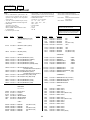
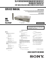
SLV-SE230/SE430/SE630/SE730/SE737/
SE830/SX730/SX737
RMT-V405/V405A/V406/V406A/V406B/V407A/V407B/V407C
SERVICE MANUAL
AEP Model
SLV-SE230B/SE230D/SE430K/SE630B/SE630D/SE630E/SE630N/
SE730B/SE730D/SE730E/SE730N/SE737E/SE830B/SE830D/
SE830E/SE830N/SX730D/SX730E/SX730N/SX737D
UK Model
SLV-SE230G/SE230I/SE730G/SE730I/SE830G
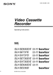
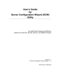
Photo: SLV-SE830N
RMT-V407A
TS-10 MECHANISM
Refer to the SERVICE MANUAL of VHS MECHANICAL ADJUSTMENT MANUAL VII for MECHANICAL
ADJUSTMENTS. (9-921-790-11)
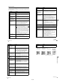
SPECIFICATIONS
System
Colour system
SE230B/SE630B/SE730B/SE830B:
SECAM (L)
VHF F2 to F10
UHF F21 to F69
CATV B to Q
HYPER S21 to S41
PAL (B/G)
VHF E2 to E12
VHF italian channels A to H
UHF E21 to E69
CATV S01 to S05, S1 to S20
HYPER S21 to S41
SE230D/SE630D/SE630E/SE730D/SE730E/
SE737E/SE830D/SE830E/SX730D/SX730E/
SX737D:
PAL (B/G)
VHF E2 to E12
VHF italian channels A to H
UHF E21 to E69
CATV S01 to S05, S1 to S20
HYPER S21 to S41
SE230G/SE730G/SE830G:
PAL (I)
UHF B21 to B69
SE230I/SE730I:
PAL (I)
VHF IA to IJ, SA10 to SA13
UHF B21 to B69
CATV S01 to S05, S1 to S20
HYPER S21 to S41
SE430K/SE630N/SE730N/SE830N/SX730N:
PAL (B/G, D/K)
VHF E2 to E12, R1 to R12
UHF E21 to E69, R21 to R69
CATV S1 to S41, S01 to S05
RF output signal
SE230D/SE230G/SE230I/SE430K/SE630D/
SE630E/SE630N/SE730D/SE730E/SE730G/
SE730I/SE730N/SE737E/SE830D/SE830E/
SE830G/SE830N/SX730D/SX730E/SX730N/
SX737D:
UHF channels 21 to 69
Aerial out
75-ohm asymmetrical aerial socket
Tape speed
SE230B:
SP: PAL 23.39 mm/s (recording/playback)
NTSC 33.35 mm/s (playback only)
SECAM
23.39 mm/s (recording/playback)
MESECAM
23.39 mm/s (playback only)
LP: NTSC 16.67 mm/s (playback only)
SECAM
11.70 mm/s (recording/playback)
MESECAM
11.70 mm/s (playback only)
SE230D:
SP: PAL 23.39 mm/s (recording/playback)
NTSC 33.35 mm/s (playback only)
LP: NTSC 16.67 mm/s (playback only)
SE230G/SE230I/SE630D/SE630E/SE730D/
SE730E/SE730G/SE730I/SE737E/SE830D/
SE830E/SE830G/SX730D/SX730E/SX737D:
SP: PAL 23.39 mm/s (recording/playback)
NTSC 33.35 mm/s (playback only)
LP: PAL 11.70 mm/s (recording/playback)
NTSC 16.67 mm/s (playback only)
EP: NTSC 11.12 mm/s (playback only)
— Continued on next page —
VIDEO CASSETTE RECORDER
SE430K/SE630N/SE730N/SE830N/SX730N:
SP: PAL/MESECAM
23.39 mm/s (recording/playback)
NTSC 33.35 mm/s (playback only)
LP: PAL/MESECAM
11.70 mm/s (recording/playback)
NTSC 16.67 mm/s (playback only)
EP: NTSC 11.12 mm/s (playback only)
SE630B/SE730B/SE830B:
SP: PAL 23.39 mm/s (recording/playback)
NTSC 33.35 mm/s (playback only)
SECAM
23.39 mm/s (recording/playback)
MESECAM
23.39 mm/s (playback only)
LP: PAL 11.70 mm/s (recording/playback)
NTSC 16.67 mm/s (playback only)
SECAM
11.70 mm/s (recording/playback)
MESECAM
11.70 mm/s (playback only)
EP: NTSC 11.12 mm/s (playback only)
Maximum recording/playback time
10 hrs. in LP mode (with E300 tape)
Rewind time
Approx. 1 min.(with E180 tape)
Inputs and outputs
LINE-1 (EURO AV)
21-pin
Video input: pin 20
Audio input: pins 2 and 6
Video output: pin 19
Audio output: pins 1 and 3
LINE-2 (DEC/EXT)/LINE-3 (DEC/EXT)
21-pin
Video input: pin 20
Audio input: pins 2 and 6
SE830B/SE830D/SE830E/SE830G/SE830N:
t LINE-2 L o R
VIDEO IN, phono jack (1)
Input signal: 1 Vp-p, 75 ohms,
unbalanced, sync negative
AUDIO IN, phono jack (2)
Input level: 327 mVrms
Input impedance: more than 47 kilohms
SE730B/SE730D/SE730E/SE730G/SE730I/
SE730N/SE737E/SE830B/SE830D/SE830E/
SE830G/SE830N/SX730D/SX730E/SX730N/
SX737D:
AUDIO (OUT/SORTIE) R/D L/G
Phono jack (2)
Rated output level: 327 mVrms
Load impedance: 47 kilohms
Output impedance: less than 10 kilohms
General
Power requirements
220 – 240 V AC, 50 Hz
Power consumption
SE230B/SE230D/SE230G/SE230I/SE430K:
15 W
1.2 W (POWER SAVE is set to ECO2, minimum)
SE630B/SE630D/SE630E/SE630N:
17 W
1.2 W (POWER SAVE is set to ECO2, minimum)
SE730B/SE730D/SE730ESE730G/SE730I/
SE730N/SE737E/SE830B/SE830D/SE830E/
SE830G/SE830N/SX730D/SX730E/SX730N/
SX737D:
17 W
1.3 W (POWER SAVE is set to ECO2, minimum)
Operating temperature
5 °C to 40 °C
Storage temperature
–20 °C to 60 °C
Dimensions including projecting parts and controls (w/h/
d)
SE230B/SE230D/SE230G/SE230I/SE430K:
Approx. 360 × 95 × 245 mm
SE630B/SE630D/SE630E/SE630N/SE730B/
SE730D/SE730E/SE730G/SE730I/SE730N/
SE737E/SX730D/SX730E/SX730N/SX737D:
Approx. 430 × 96 × 245 mm
SE830B/SE830D/SE830E/SE830G/SE830N:
Approx. 430 × 96 × 253 mm
Mass
SE230B/SE230D/SE230G/SE230I/SE430K:
Approx. 2.8 kg
SE630B/SE630D/SE630E/SE630N/SE730B/
SE730D/SE730E/SE730G/SE730I/SE730N/
SE737E/SE830B/SE830D/SE830E/SE830G/
SE830N/SX730D/SX730E/SX730N/SX737D:
Approx. 3.1 kg
Supplied accessories
Remote commander (1)
R6 (size AA) batteries (2)
Aerial cable (1)
SE230B/SE630B/SE730B/SE830B:
PERITEL cable (1)
Design and specifications are subject to change without
notice.
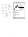
SAFETY CHECK-OUT
After correcting the original service problem, perform the following
safety checks before releasing the set to the customer:
1. Check the area of your repair for unsoldered or poorly-soldered
connections. Check the entire board surface for solder splashes
and bridges.
4. Look for parts which, though functioning, show obvious signs
of deterioration. Point them out to the customer and recommend
their replacement.
2. Check the interboard wiring to ensure that no wires are
“pinched” or contact high-wattage resistors.
5. Check the B+ voltage to see it is at the values specified.
3. Look for unauthorized replacement parts, particularly transistors,
that were installed during a previous repair. Point them out to
the customer and recommend their replacement.
SAFETY-RELATED COMPONENT WARNING!!
COMPONENTS IDENTIFIED BY MARK 0 OR DOTTED
LINE WITH MARK 0 ON THE SCHEMATIC DIAGRAMS
AND IN THE PARTS LIST ARE CRITICAL TO SAFE
OPERATION. REPLACE THESE COMPONENTS WITH
SONY PARTS WHOSE PART NUMBERS APPEAR AS
SHOWN IN THIS MANUAL OR IN SUPPLEMENTS
PUBLISHED BY SONY.
—2—
Important Service Guide
TABLE OF CONTENTS
3. P.C.Boards
◆ Mode Switch (Program Switch) Assembly Point ························· 4
◆ How to eject the cassette tape
(If the unit does not operate on condition that tape is inserted
into housing ass’y) ································································· 4
3-1
3-2
3-3
3-4
Main PCB (Main A model) ················································ 3-3
Main PCB (Main B model) ················································ 3-7
Function PCB (Hi-Fi model) ············································ 3-11
Dial Timer PCB (SE830) ·················································· 3-11
1.
4.
Schematic Diagrams
General
Getting Started
Index to parts and controls ················································· 1-1
Step 1 : Unpacking ····························································· 1-2
Step 2 : Setting up the remote commander ························· 1-3
Step 3 : Connecting the VCR ············································· 1-4
Step 4 : Setting up the VCR with the Auto
Set Up function ····················································· 1-5
Step 5 : Selecting the TV system ········································ 1-5
Setting the clock ···················································· 1-6
Downloading the TV tuner’s preset data ··············· 1-6
Selecting a language ·············································· 1-6
Presetting channels ················································ 1-7
Changing/disabling programme positions ············· 1-7
Setting the Canal Plus decoder ······························ 1-9
Basic Operations
Playing a tape ····································································· 1-9
Recording TV programmes ·············································· 1-10
Recording TV programmes using the Dial Timer ············ 1-11
Recording TV programmes using
the Show ViewR system ···················································· 1-12
Recording TV programmes using the timer ····················· 1-13
Additional Operations
Playing/searching at various speeds ································· 1-14
Setting the recording duration time ·································· 1-15
Checking/changing/cancelling timer settings ··················· 1-15
Recording stereo and bilingual programmes ···················· 1-15
Searching using the index function ·································· 1-16
Adjusting the picture ························································ 1-17
Reducing the VCR’s power consumption ························ 1-17
Changing menu options ···················································· 1-17
Editing
Connecting to a VCR or stereo system ····························· 1-18
Basic editing ····································································· 1-18
Audio dubbing ·································································· 1-18
Additional Information
Troubleshooting ································································ 1-19
Index ················································································· 1-20
Quick Start Guide ······································································· 1-20
2.
Disassembly
2-1
2-1-1
2-1-2
2-1-3
2-1-4
2-2
2-2-1
2-2-2
2-2-3
2-2-4
2-2-5
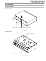
Mono Models
Cabinet Top ········································································
Cover Bottom ·····································································
Ass’y-Panel Front ·······························································
Ass’y Main PCB, Deck ······················································
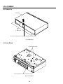
Hi-Fi Models
Cabinet Top ········································································
Cover Bottom ·····································································
Ass’y-Panel Front ·······························································
Ass’y Jack PCB ··································································
Ass’y Main PCB, Deck ······················································
◆ Block Identification of Main PCB ············································ 4-3
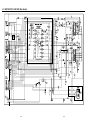
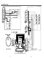
4-1 S.M.P.S. (Main A model) ··················································· 4-5
4-2 S.M.P.S. (Main B model) ··················································· 4-7
4-3 Power (Main A model) ······················································· 4-9
4-4 Power (Main B model) ····················································· 4-11
4-5 System Control/Servo (Main A model) ···························· 4-13
4-6 System Control/Servo (Main B model) ···························· 4-15
4-7 Audio/Video ····································································· 4-17
4-8 Hi-Fi (Hi-Fi model) ·························································· 4-19
4-9 TM-Block ········································································· 4-21
4-10 OSD/VPS/PDC ································································· 4-23
4-11 SECAM (SE230B/SE630B/SE730B/SE830B) ················ 4-25
4-12 A2/NICAM (Hi-Fi model) ··············································· 4-27
4-13 Input-Output (2 Scart Jack) (Main A model) ··················· 4-29
4-14 Input-Output (2 Scart Jack) (Main B model) ··················· 4-31
4-15 Function (SE630) ····························································· 4-33
4-16 Function (Main B model) ················································· 4-35
5.
Alignment and Adjustment
5-1 Reference ············································································
5-1-1 Location of adjustment button of remote control ···············
5-1-2 Test point location for adjustment mode setting
(Mono model) ·····································································
5-1-3 SW7T01 (TEST) location for adjustment mode setting
(Hi-Fi model) ······································································
5-2 Mechanical Adjustment ······················································
5-2-1 The number and position of test point ································
5-2-2 ACE Head Position (X-Point) Adjustment ·························
5-3 Head Switching Point Adjustment ·····································
5-4 NVRAM Option Setting ·····················································
6.
Repair Parts List
6-1
6-1-1
6-1-2
6-1-3
6-1-4
6-2
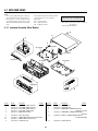
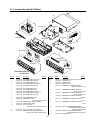
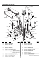
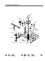
Exploded Views ··································································
Instrument Assembly (Mono Models) ································
Instrument Assembly (Hi-Fi Models) ·································
Mechanical Parts (Top Side) ··············································
Mechanical Parts (Bottom Side) ·········································
Electrical Parts List ····························································
2-1
2-1
2-2
2-3
2-4
2-4
2-5
2-5
2-6
• Main A model: SE230/SE430/SE630
Main B model: SE730/SE737/SE830/SX730/SX737
Hi-Fi model: SE630/SE730/SE737/SE830/SX730/SX737
Mono model: SE230/SE430
—3—
5-1
5-1
5-2
5-3
5-4
5-4
5-4
5-5
5-5
6-2
6-2
6-3
6-4
6-5
6-6
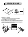
IMPORTANT SERVICE GUIDE
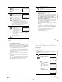
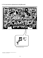
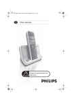
◆ MODE SWITCH (PROGRAM SWITCH) ASSEMBLY POINT
1) When installing the ass’y deck on the Main PCB, be sure to align the assembly point of mode switch.
ASSEMBLY POINT
(ALIGN TWO ARROWS)
Fig. 1
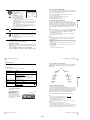
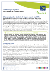
◆ HOW TO EJECT THE CASSETTE TAPE
(If the unit does not operate on condition that tape is inserted into housing ass’y)
1) Turn the Gear Worm 1 clockwise in the direction of arrow with screw driver. (See Fig. 2)
(Other method ; Remove the screw of Motor Load Ass’y, Separate the Motor Load Ass’y)
2) When Slider S, T are approached in the position of unloading, rotate holder Clutch counterclockwise after inserting screw driver in the
hole of frame’s bottom in order to wind the unwiunded tape. (Refer to Fig. 3)
(If you rotate Gear Worm 1 continuously when tape is in state of unwinding, you may cause a tape contamination by grease and
tape damage. Be sure to wind the unwiunded tape in the state of set horizontally.)
3) Rotate Gear Worm 1 clockwise using screw driver again up to the state of eject mode and then pick out the tape. (Refer to Fig. 2)
1 GEAR WORM
FRAME
Fig. 2
Fig. 3
—4—
SLV-SE230/SE430/SE630/SE730/
SE737/SE830/SX730/SX737
1. GENERAL
This section is extracted from SLV-SE430K/SE630N/SE730N/
SE830N/SX730N instruction manual. (3-081-623-11)
Getting Started
For SLV-SE730N, SX730N and SE630N
Getting Started
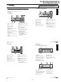
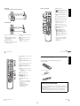
Index to parts and controls
Refer to the pages indicated in parentheses ( ) for details.
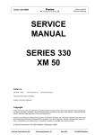
Front panel
For SLV-SE830N
A ?/1 (on/standby) switch
G M (fast-forward) button (39) (58)
B Remote sensor (12)
H REC z (record) button (43) (60)
(74)
C Tape compartment
A ?/1 (on/standby) switch
L X (pause) button (39) (50) (74) (75)
B Remote sensor (12)
M PROGRAM +/– buttons* (47) (59)
(68)
C Tape compartment
D A (eject) button (39)
E m (rewind) button (39) (58)
F Shuttle ring (58)
G H (play) button* (39) (58)
H M (fast-forward) button (39) (58)
I JOG button (58)
J REC z (record) button (43) (60)
(74)
K x (stop) button* (22) (39) (74) (75)
N
I x (stop) button* (22) (39) (74) (75)
D A (eject) button (39)
J X (pause) button (39) (74) (75)
E m (rewind) button (39) (58)
K PROGRAM +/– buttons* (59) (68)
F H (play) button* (39) (58)
* The H (play), x (stop) and
PROGRAM + buttons have a tactile dot.
DIAL TIMER (46)
O AUDIO DUB button (75)
P t LINE-2 L (left) o R (right)
jacks (covered)* (72) (73) (75)
How to open the jack cover
1 Press the bottom of the cover.
2 Hook your finger on the top edge of the
cover and pull it open.
* The H (play), x (stop) and
PROGRAM + buttons and jack cover
have a tactile dot.
continued
Index to parts and controls
4 Index to parts and controls
For SLV-SE430K
Display window
1
2
8 7
A ?/1 (on/standby) switch
G M (fast-forward) button (39) (58)
B A (eject) button (39)
H REC z (record) button (43) (60)
(74)
D Tape compartment
E m (rewind) button (39) (58)
F H (play) button* (39) (58)
I x (stop) button* (22) (39) (74) (75)
K PROGRAM +/– buttons* (59) (68)
4
5
6
A Tape indicator
E TV indicator (45)
B VIDEO indicator (17) (43)
F STEREO indicator (63)
C Time counter/clock/line/programme
position indicator (40) (42) (74)
G Tape speed indicators (42)
D
J X (pause) button (39) (74) (75)
3
(smartlink) indicator (18)
Getting Started
For SLV-SE830N, SE730N and SX730N
C Remote sensor (12)
5
H Timer/recording indicator (43) (48)
(53) (56)
For SLV-SE630N and SE430K
* The H (play), x (stop) and
PROGRAM + buttons have a tactile dot.
A Tape indicator
E STEREO indicator* (63)
B Time counter/clock/line/programme
position indicator (40) (42) (74)
F VIDEO indicator (17) (43)
C Timer indicator (48) (53) (56)
G Playback indicator
* not available on SLV-SE430K
D Recording indicator (43)
continued
Index to parts and controls
6 Index to parts and controls
1-1
7
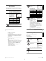
Rear panel
A Z (eject) button (39)
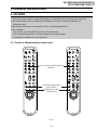
Remote commander
B
(wide) button (for TV) (14) (15)
C
DISPLAY button (14) (40) (43)
D COUNTER/REMAIN button (43)
E Programme number buttons*1 (13)
(44)
Getting Started
For SLV-SE830N, SE730N, SX730N and SE630N
F - (ten’s digit) button (13) (44)
1
2
3
G / (Teletext) button (for TV)*2 (14)
4
5
6
8
9
H 2 (volume) +/– buttons (for TV)
(13)
7
0
For SLV-SE430K
I a TV power on/TV mode select
button (for TV)*2 (13)
J z REC (record) button (43) (60)
K SP (Standard Play)/LP (Long Play)
button (42)
L MENU button (24) (61)
A
(in from antenna) connector (16)
(17)
B LINE-3 (DEC/EXT) connector*1
LINE-2 (DEC/EXT) connector*2
(19) (36) (73)
C Mains lead (16) (17)
D AUDIO (OUT/SORTIE) R/D (right)
L/G (left) jacks*3 (19)
M X (pause)/M button (24) (39)
x (stop)/m button (24) (39)
m (rewind)/< button (24) (39)
(58)
M (fast-forward)/, button (24)
(39) (58)
H (play)/OK button*1 (24) (39)
(58)
E LINE-1 (EURO AV) connector (17)
(36) (72)
F
(out to tv) connector (16) (17)
*1 The H (play), AUDIO MONITOR,
number 5 and PROG + buttons have a
tactile dot.
*2 SLV-SE830N only
*1 SLV-SE830N
*2 SLV-SE730N, SX730N, SE630N and
SE430K
*3 not available on SLV-SE630N
continued
Index to parts and controls
8 Index to parts and controls
N [TV] / [VIDEO] remote control switch
(12)
Getting Started
Step 1 : Unpacking
O ?/1 (on/standby) switch (13) (14)
(53)
Check that you have received the following items with the VCR:
P AUDIO MONITOR button*1*3 (14)
(64)
9
• Remote commander
Q t TV/VIDEO button (13) (17) (43)
R CLEAR button (40) (52) (61)
1
2
3
4
5
6
7
8
9
S INPUT SELECT button (42) (56)
(74)
T PROG (programme) +/– buttons*1
(13) (42)
0
• R6 (size AA) batteries
c ⁄ C Teletext page access buttons
(for TV)*2 (14)
U y SLOW button*4 (58)
V ×2 button*4 (58)
• Aerial cable
W ./> (index search)
buttons*3*4 (66)
X
TIMER button (51) (55)
*1 The H (play), AUDIO MONITOR,
number 5 and PROG + buttons have a
tactile dot.
*2 SLV-SE830N only
3
* not available on SLV-SE430K
*4 FASTEXT buttons (for TV)
(SLV-SE830N only)
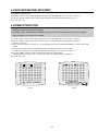
Check your model name
The instructions in this manual are for the 5 models: SLV-SE830N, SE730N,
SX730N, SE630N and SE430K. Check your model name by looking at the rear
panel of your VCR.
SLV-SE830N is the model used for illustration purposes. Any difference in
operation is clearly indicated in the text, for example, “SLV-SE830N only.”
10 Index to parts and controls
Unpacking
1-2
11
?/1
Inserting the batteries
AUDIO MONITOR
DISPLAY
Insert two R6 (size AA) batteries
by matching the + and – on the
batteries to the diagram inside the
battery compartment.
t TV/VIDEO
Insert the negative (–) end first,
then push in and down until the
positive (+) end clicks into
position.
1
2
3
4
5
6
7
8
9
-
Getting Started
Step 2 : Setting up the remote commander
Programme
number
buttons
0
/
Using the remote
commander
You can use this remote
commander to operate this VCR
and a Sony TV. Buttons on the
remote commander marked with a
dot (•) can be used to operate your
Sony TV. If the TV does not have
the
symbol near the remote
sensor, this remote commander
will not operate the TV.
PROG +/–/
c⁄ C
2 +/–
a
Remote sensor
FASTEXT buttons
[TV] /
[VIDEO]
1
2
3
4
5
6
7
8
9
0
TV control buttons
To operate
Set [TV] / [VIDEO] to
the VCR
[VIDEO] and point at the remote sensor at the VCR
a Sony TV
[TV] and point at the remote sensor at the TV
To
Press
Set the TV to standby mode
?/1
Select an input source: aerial in or line in
t TV/VIDEO
Select the TV’s programme position
Programme number buttons,
-, PROG +/–
Adjust the volume of the TV
2 +/–
Switch to TV (Teletext off)*1
a (TV)
continued
Setting up the remote commander
12 Setting up the remote commander
Press
Switch to Teletext*1
/ (Teletext)
Select the sound*2
AUDIO MONITOR
Use FASTEXT*1
FASTEXT buttons
Call up the on-screen display
Change the Teletext page*1
Switch to/from wide mode of a Sony wide TV (For
other manufactures’ wide TVs, see “Controlling
other TVs with the remote commander (SLVSE830N only)” below.)
Code numbers of controllable TVs
If more than one code number is listed, try entering them one at a time until
you find the one that works with your TV.
To switch to wide mode, see the footnotes below this table for the applicable
code numbers.
DISPLAY
c⁄ C
(wide)
Notes
• With normal use, the batteries should last about three to six months.
• If you do not use the remote commander for an extended period of time, remove
the batteries to avoid possible damage from battery leakage.
• Do not use a new battery together with an old one.
• Do not use different types of batteries together.
• Some buttons may not work with certain Sony TVs.
*1 SLV-SE830N only
*2 not available on SLV-SE430K
Manufacturer
Code number
Manufacturer
Sony
01*1, 02
Panasonic
17*1, 49
Akai
68
Philips
06*1, 07*1, 08*1
Ferguson
52
Saba
12, 13
Grundig
10*1, 11*1
Samsung
22, 23
Hitachi
24
Sanyo
25
JVC
33
Sharp
29
Loewe
45
Telefunken
36
Mivar
09, 70
Thomson
43*2
NEC
66
Toshiba
38
Nokia
15, 16, 69*3
Getting Started
To
13
Code number
*1 Press
(wide) to switch the wide picture mode on or off.
*2 Press
(wide), then press 2 +/– to select the wide picture mode you want.
3
* Press
(wide). The menu appears on the TV screen. Then, press M/m/</, to
select the wide picture you want and press OK.
Controlling other TVs with the remote commander
(SLV-SE830N only)
The remote commander is preprogrammed to control non-Sony TVs. If your
TV is listed in the following table, set the appropriate manufacturer’s code
number.
Tip
• When you set your TV’s code number correctly while the TV is turned on, the TV
turns off automatically.
1
down ?/1, and enter your TV’s code number using the programme
2 Hold
number buttons. Then release ?/1.
Set [TV] / [VIDEO] at the top of the remote commander to [TV].
Notes
• If you enter a new code number, the code number previously entered will be
erased.
• If the TV uses a different remote control system from the one programmed to work
with the VCR, you cannot control your TV with the remote commander.
• When you replace the batteries of the remote commander, the code number may
change. Set the appropriate code number every time you replace the batteries.
Now you can use the following TV control buttons to control your TV:
?/1, t TV/VIDEO, programme number buttons, - (ten’s digit),
PROG +/–, 2 +/–, a (TV), / (Teletext), FASTEXT buttons,
(wide)*, MENU*, M/m/</,*, and OK*.
* These buttons may not work with all TVs.
14 Setting up the remote commander
Setting up the remote commander
1-3
15
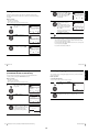
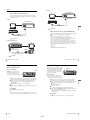
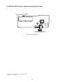
If your TV has a Scart (EURO-AV) connector
If your TV has a Scart (EURO-AV) connector, see page 17.
If your TV does not have a Scart (EURO-AV) connector
LINE-1
(EURO AV)
Mains lead
AERIAL IN
Scart
(EURO-AV)
Mains lead
AERIAL IN
: Signal flow
to mains
Aerial cable (supplied)
to mains
Aerial cable (supplied)
Scart cable (not supplied)
1
Disconnect the aerial cable from
your TV and connect it to
on
the rear panel of the VCR.
: Signal flow
1
Disconnect the aerial cable from your
TV and connect it to
on the rear
panel of the VCR.
2
Connect
of the VCR and the
aerial input of your TV using the
supplied aerial cable.
2
Connect
of the VCR and the aerial
input of your TV using the supplied
aerial cable.
3
Connect LINE-1 (EURO AV) on
the VCR and the Scart (EUROAV) connector on the TV with the
optional Scart cable.
3
Getting Started
Step 3 : Connecting the VCR
This connection improves picture
and sound quality. Whenever you
want to watch the VCR picture,
press t TV/VIDEO to display
the VIDEO indicator in the
display window.
Connect the mains lead to the mains.
Note
• When you connect the VCR and your TV only with an aerial cable, you have to
tune your TV to the VCR (see page 20).
4
Connect the mains lead to the mains.
continued
Connecting the VCR
16 Connecting the VCR
Additional connections
To a stereo system (not
available on SLV-SE630N
and SE430K)
You can improve sound
quality by connecting a
stereo system to the AUDIO
R/D L/G jacks as shown on
the right.
If the connected TV complies with
SMARTLINK, MEGALOGIC*1,
EASYLINK*2, Q-Link*3, EURO
VIEW LINK*4, or T-V LINK*5, this
VCR automatically runs the
SMARTLINK function after you complete the steps on the previous page
(the
indicator appears in the VCR’s display window when you turn on the
TV). You can enjoy the following SMARTLINK features.
Getting Started
About the SMARTLINK features (not available on SLV-SE630N and
SE430K)
17
AUDIO R/D L/G
LINE IN
Audio cable (not supplied)
: Signal flow
• TV Direct Rec
You can easily record what you are watching on the TV when the VCR is
turned on. For details, see “Recording what you are watching on the TV
(TV Direct Rec) (not available on SLV-SE630N and SE430K)” on page
45.
• One Touch Play
With One Touch Play, you can start playback automatically without turning
on the TV. For details, see “Starting playback automatically with one
button (One Touch Play) (not available on SLV-SE630N and SE430K)” on
page 41.
• One Touch Menu
When the VCR is turned on, you can turn on the TV, set the TV to the
video channel, and display the VCR’s on-screen display automatically by
pressing MENU on the remote commander.
• One Touch Timer
When the VCR is turned on, you can turn on the TV, set the TV to the
video channel, and display the timer recording menu (the TIMER
PROGRAMMING menu or the SHOWVIEW menu) automatically by
pressing TIMER on the remote commander.
You can set which timer recording menu is displayed using TIMER
METHOD in the EASY OPERATION menu (see page 71).
• NexTView Download
You can easily set the timer by using the NexTView Download function on
your TV. Please refer to your TV’s instruction manual.
To a satellite or digital
tuner with Line Through
Using the Line Through
function, you can watch
programmes from a satellite
or digital tuner connected to
this VCR on the TV even
when the VCR is turned off.
When you turn on the
satellite or digital tuner, this
VCR automatically sends the
signal from the satellite or
digital tuner to the TV
without turning itself on.
LINE-3 (DEC/EXT)*1 or
LINE-2 (DEC/EXT)*2
LINE
OUT
Scart cable (not supplied)
: Signal flow
the satellite or digital tuner to the LINE-3 (DEC/EXT)*
1 Connect
LINE-2 (DEC/EXT)* connector as shown above.
Turn off the VCR.
2
1
or
2
To watch a programme, turn on the satellite or digital tuner and the TV.
Notes
• The Line Through function will not operate properly if POWER SAVE in the
USER SET menu is set to ECO2. Set POWER SAVE to OFF or ECO1 to ensure
proper operation (see page 69).
• You cannot watch programmes on the TV while recording unless you are recording
a satellite or digital programme.
• This function may not work with some types of satellite or digital tuners.
• When the VCR is turned off, set the TV to the video channel.
*1 “MEGALOGIC” is a registered trademark of Grundig Corporation.
*2 “EASYLINK” is a trademark of Philips Corporation.
*3 “Q-Link” is a trademark of Panasonic Corporation.
*4 “EURO VIEW LINK” is a trademark of Toshiba Corporation.
*5 “T-V LINK” is a trademark of JVC Corporation.
*1 SLV-SE830N
*2 SLV-SE730N, SX730N, SE630N and SE430K
Note
• Not all TVs respond to the functions above.
18 Connecting the VCR
Connecting the VCR
1-4
19
4
Press OK.
OK
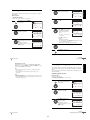
Before using the VCR for the first time, set up the VCR using the Auto Set Up
function. With this function, you can set the language for the on-screen display, TV
channels, guide channels for the ShowView system*, and VCR clock* automatically.
1
If your TV does not have a Scart (EURO-AV) connector, tune the
TV to channel 32 (the initial RF channel for this VCR). Refer to
your TV manual for TV tuning instructions. If the picture does not
appear clearly, see “To change the RF channel” on page 22.
Connect the mains lead to the
mains.
GB
CZ
TR
The VCR automatically turns on,
and the language abbreviations
appear on the TV screen.
The abbreviations of the
languages are as follows:
3
SELECT
SET
Abbreviation
Country
Language
CZ
Czecho
Czech
HU
Hungary
Hungarian
PL
Poland
Polish
SK
Slovakia
Slovak
TR
Turkey
Turkish
RU
Russia
Russian
RU
HU
:
: OK
PL
SK
EXIT
: MENU
5
OK
I
N
P
E
S
CH
SELECT
SET
TR
GR
HU
PL
CZ
OTHERS
:
: OK
EXIT
: MENU
Abbreviation Country
Abbreviation Country
A
Austria
E
B
Belgium
S
Sweden
DK
Denmark
CH
Switzerland
FIN
Finland
TR
Turkey
D
Germany
GR
Greece
NL
Netherlands
HU
Hungary
I
Italy
PL
Poland
N
Norway
CZ
Czech
P
Portugal
OTHERS
other countries
For SLV-SE830N, SE730N and
SX730N
Press M/m/</, to select the
abbreviation of your country from
the table in step 4, then press OK.
If your country does not appear,
select OTHERS.
Spain
AUTO SET UP
PLEASE WAIT
40%
EXIT
: MENU
The VCR starts searching for all of
the receivable channels and presets
them (in the appropriate order for your local area).
If you want to change the order of the channels or disable unwanted
programme positions, see “Changing/disabling programme
positions” on page 31.
Press M/m/</, to select the language abbreviation from the table
in step 2, then press OK.
OK
A
B
DK
FIN
D
NL
The abbreviations of the
countries are as follows:
Turn on your TV and set it to the video channel.
2
COUNTRY SELECTION
The COUNTRY SELECTION
menu* appears.
Getting Started
Step 4 : Setting up the VCR with the Auto
Set Up function
After the search or download is complete, the current time appears
for any stations that transmit a time signal. If the time does not
appear, set the clock manually. See “Setting the clock” on page 24.
The message for the Auto Set Up function appears.
For SLV-SE630N and SE430K
The clock setting menu appears. See “Setting the clock” on
page 24.
continued
Setting up the VCR with the Auto Set Up function
20 Setting up the VCR with the Auto Set Up function
To cancel the Auto Set Up function
Press MENU.
Getting Started
Step 5 : Selecting the TV system
To change the RF channel
If the picture does not appear clearly on the TV, change the RF channel on
the VCR and TV. Select INSTALLATION from the menu, then press M/m
to highlight VCR OUTPUT CH and press ,. Select the RF channel by
pressing the M/m buttons. Then, tune the TV to the new RF channel so that
a clear picture appears.
21
You must select the appropriate TV system for your area.
Before you start…
• Turn on the VCR and the TV.
• Set the TV to the video channel.
• Refer to “Index to parts and controls” for button locations.
Tip
• If you want to change the language for the on-screen display from the one preset in
the Auto Set Up function, see page 27.
1
Notes
• Whenever you operate the Auto Set Up function, some of the settings
(ShowView*, timer, etc.) will be reset. If this happens, you have to set them again.
• Auto preset starts automatically only when you plug in the mains lead for the first
time after you purchase the VCR.
• After using the Auto Set Up function, the language abbreviations do not appear
automatically when you connect the mains lead again. If you want to use the Auto
Set Up function again, press MENU, then press M/m/</, to highlight
INSTALLATION and press OK. Press M/m to highlight AUTO SET UP, then
repeat all procedures from step 4.
• Auto preset can be performed by pressing x (stop) on the VCR continuously for
5 seconds or more with no tape inserted.
MENU
Press MENU, then press M/m/</
, to highlight INSTALLATION
and press OK.
OK
2
AUTO SET UP
MANUAL SET UP
SMARTLINK
TV SYSTEM
VCR OUTPUT CH
SELECT
END
:
: OK
:G
:32
SET
EXIT
:
: MENU
Press M/m to highlight TV
SYSTEM, then press ,.
AUTO SET UP
MANUAL SET UP
SMARTLINK
TV SYSTEM
VCR OUTPUT CH
OK
:G
:32
* not available on SLV-SE630N and SE430K
SELECT
END
3
:
: OK
SET
EXIT
:
: MENU
Press , to select the appropriate TV system. Select “G” for the
B/G TV system, or “K” for the D/K TV system.
OK
4
22 Setting up the VCR with the Auto Set Up function
MENU
Press MENU to exit the menu.
Selecting the TV system
1-5
23
You must set the time and date on the VCR to use the timer features properly.
Set the day, month, and year in
sequence by pressing , to select
the item to be set, and press M/m to
select the digits, then press ,.
The Auto Clock Set function* works only if a station in your area is broadcasting a
time signal.
The day of the week is set
automatically.
OK
18 :30
2 8 / SEP / 2 0 0 3
SUN
AUTO CLOCK
SELECT
END
:
: OK
: ON
SET
EXIT
:
: MENU
Getting Started
4
Setting the clock
Before you start…
• Turn on the VCR and the TV.
• Set the TV to the video channel.
• Refer to “Index to parts and controls” for button locations.
5
OK
1
MENU
Press MENU, then press M/m/</
, to highlight CLOCK SET and
press OK.
12 :00
OK
:
: OK
SELECT
END
The VCR automatically sets the
clock according to the time signal
broadcast between the channels
PR 1 to PR 5.
1 / JAN / 2 0 0 3
WE D
AUTO CLOCK
: ON
SET
EXIT
18 :30
2 8 / SEP / 2 0 0 3
SUN
AUTO CLOCK
SELECT
END
:
: OK
:
: MENU
:
: MENU
MENU
Press MENU to exit the menu.
Press M/m to set the hour.
OK
18 :00
SELECT
END
3
Tips
• If you set AUTO CLOCK* to ON, the Auto Clock Set function is activated
whenever the VCR is turned off. The time is adjusted automatically by making
reference to the time signal from the station.
• To change the digits while setting, press < to return to the item to be changed, and
select the digits by pressing M/m.
1 / JAN / 2 0 0 3
WE D
AUTO CLOCK
:
: OK
: ON
SET
EXIT
:
: MENU
Press , to select the minutes and
set the minutes by pressing M/m.
OK
* not available on SLV-SE630N and SE430K
18 :30
1 / JAN / 2 0 0 3
WED
AUTO CLOCK
SELECT
END
:
: OK
: ON
SET
EXIT
:
: MENU
24 Setting the clock
Setting the clock
Selecting a language
(SLV-SE830N, SE730N and SX730N only)
You can change the on-screen display language from the one you selected with the
Auto Set Up function.
You can download your TV tuner’s preset data to the VCR and tune the VCR
according to that data using the SMARTLINK connection.
Before you start…
• Turn on the VCR and the TV.
• Set the TV to the video channel.
• Refer to “Index to parts and controls” for button locations.
Before you start…
• Turn on the VCR and the TV.
• Set the TV to the video channel.
• Refer to “Index to parts and controls” for button locations.
MENU
Press MENU, then press M/m/</
, to highlight INSTALLATION
and press OK.
OK
1
AUTO SET UP
MANUAL SET UP
SMARTLINK
TV SYSTEM
VCR OUTPUT CH
SELECT
END
:
: OK
:G
:32
SET
EXIT
MENU
Press M/m to highlight
SMARTLINK, then press ,.
OK
Press MENU, then press M/m/</
, to highlight LANGUAGE SET
and press OK.
GB
CZ
TR
RU
HU
PL
SK
OK
SELECT
SET
:
: OK
EXIT
: MENU
:
: MENU
2
2
25
Getting Started
Downloading the TV tuner’s preset data
1
: ON
SET
EXIT
If you do not need the Auto Clock
Set function, select OFF.
6
2
Press M/m to select ON for the
setting of the Auto Clock Set
function*.
Press M/m/</, to highlight the abbreviation of the desired
language from the table on page 20, then press OK.
OK
SMARTLINK
TV CH DOWNLOAD
TV DIRECT RECORD : OFF
SELECT
END
3
OK
Press M/m to highlight TV CH
DOWNLOAD, then press ,. The
Preset Download function starts and
the
indicator flashes in the
display window during download.
:
: OK
SET
EXIT
:
: MENU
TV CH DOWNLOAD
PLEASE WAIT
40%
END
: OK
START:
EXIT : MENU
26 Downloading the TV tuner’s preset data (SLV-SE830N, SE730N and SX730N only)
Selecting a language
1-6
27
Press </, repeatedly until the
channel you want is displayed.
If some channels could not be preset using the Auto Set Up function, you can preset
them manually.
Before you start…
SELECT
END
• Turn on the VCR and the TV.
• Set the TV to the video channel.
• Refer to “Index to parts and controls” for button locations.
1
MENU
Press MENU, then press M/m/</
, to highlight INSTALLATION
and press OK.
MANUAL TUNING
PR
CH
MFT
DECODER
NAME
OK
5
Press M/m to highlight NAME, then
press ,.
AUTO SET UP
MANUAL SET UP
SMARTLINK
TV SYSTEM
VCR OUTPUT CH
:G
:32
5
033
–
OFF
––––
SET
EXIT
:
: OK
:
: MENU
MANUAL TUNING
PR
CH
MFT
DECODER
NAME
OK
:
:
:
:
:
Getting Started
4
Presetting channels
SELECT
END
:
:
:
:
:
5
033
–
OFF
––––
SET
EXIT
:
: OK
:
: MENU
OK
SELECT
END
:
: OK
SET
EXIT
:
: MENU
6
2
Press M/m to highlight MANUAL
SET UP, then press ,.
CH
027
029
030
032
DELETE
3
OK
Press M/m to highlight the row
which you want to preset, then press
,.
To display other pages for
programme positions 6 to 80, press
M/m repeatedly.
OK
TV STATION TABLE
PR
1
2
3
4
5
OK
NAME
AAB–
L MN –
CDE –
I J K–
Enter the station name.
DEC
OFF
OFF
OFF
OFF
AtBt…tZt0t1t
…t9tA
SWAPPING : OK
: CLEAR
EXIT : MENU
SELECT
END
:
: OK
:
:
:
:
:
5
–––
–
OFF
––––
SET
EXIT
MANUAL TUNING
PR
CH
MFT
DECODER
NAME
SELECT
END
:
:
:
:
:
5
033
–
OFF
O– – –
SET
EXIT
:
: OK
:
: MENU
2 Press , to set the next
character.
The next space is flashed.
To correct a character, press </, until the character you want
to correct is flashed, then reset it.
MANUAL TUNING
PR
CH
MFT
DECODER
NAME
1 Press M/m to select a character.
Each time you press M, the
character changes as shown
below.
You can set up to 4 characters for the station name.
7
:
: MENU
Press OK to confirm the station name.
OK
8
MENU
Press MENU to exit the menu.
continued
Presetting channels
28 Presetting channels
Changing/disabling programme positions
After setting the channels, you can change the programme positions as you like. If
any programme positions are unused or contain unwanted channels, you can disable
them.
Tips
• To set the programme position for the decoder, see “Setting the Canal Plus
decoder” on page 36.
• The VCR must receive channel information for station names to appear
automatically.
You can also change the station names. If the station names are not displayed, you can
enter them manually.
Getting Started
If the picture is not clear
If the picture is not clear, you may use the Manual Fine Tuning (MFT)
function. After step 4, press M/m to select MFT. Press </, to get a clear
picture, then press MENU to exit the menu.
29
Changing programme positions
Notes
• If the TV sound is distored or noisy, select the appropriate TV system (“G” or “K”)
for your area (see page 23).
• When adjusting MFT, the menu may become difficult to read due to interference
from the picture being received.
Before you start…
• Turn on the VCR and the TV.
• Set the TV to the video channel.
• Refer to “Index to parts and controls” for button locations.
1
MENU
Press MENU, then press M/m/</
, to highlight INSTALLATION
and press OK.
AUTO SET UP
MANUAL SET UP
SMARTLINK
TV SYSTEM
VCR OUTPUT CH
:G
:32
OK
SELECT
END
2
Press M/m to highlight MANUAL
SET UP, then press ,.
CH
027
029
030
032
DELETE
3
OK
Press M/m to highlight the row
containing the programme position
you want to change.
To display other pages for
programme positions 6 to 80, press
M/m repeatedly.
SET
EXIT
:
: MENU
TV STATION TABLE
PR
1
2
3
4
5
OK
:
: OK
NAME
AAB–
L MN –
CDE –
I J K–
DEC
OFF
OFF
OFF
OFF
SWAPPING : OK
: CLEAR
EXIT : MENU
TV STATION TABLE
PR
1
2
3
4
5
CH
027
029
030
032
DELETE
NAME
AAB–
L MN –
CDE –
I J K–
DEC
OFF
OFF
OFF
OFF
SWAPPING : OK
: CLEAR
EXIT : MENU
continued
Changing/disabling programme positions
30 Presetting channels
1-7
31
Press OK, then press M/m to move
to the desired programme position.
2
TV STATION TABLE
PR
1
2
3
4
5
OK
CH
027
NAME
AAB–
DEC
OFF
030
032
029
CDE –
I J K–
L MN –
OFF
OFF
OFF
Press M/m to highlight MANUAL
SET UP, then press ,.
SWAPPING : OK
EXIT : MENU
5
3
OK
7
Press M/m to highlight the row
which you want to disable.
OK
4
5
Before you start…
• Turn on the VCR and the TV.
• Set the TV to the video channel.
• Refer to “Index to parts and controls” for button locations.
MENU
Press MENU, then press M/m/</
, to highlight INSTALLATION,
and press OK.
CH
027
029
030
032
The selected row will be cleared as
shown on the right.
6
NAME
AAB–
L MN –
CDE –
I J K–
DEC
OFF
OFF
OFF
OFF
SWAPPING : OK
: CLEAR
EXIT : MENU
TV STATION TABLE
PR
1
2
3
4
5
CH
027
NAME
AAB–
DEC
OFF
030
032
CDE –
I J K–
OFF
OFF
DELETE
After presetting channels, you can disable unused programme positions. The disabled
positions will be skipped later when you press the PROG +/– buttons.
SWAPPING : OK
: CLEAR
EXIT : MENU
Press CLEAR.
CLEAR
Disabling unwanted programme positions
1
PR
1
2
3
4
5
DELETE
Press MENU to exit the menu.
DEC
OFF
OFF
OFF
OFF
TV STATION TABLE
To display other pages for
programme positions 6 to 80, press
M/m repeatedly.
To change the programme position of another station, repeat steps 3
through 5.
MENU
NAME
AAB–
L MN –
CDE –
I J K–
CH
027
029
030
032
DELETE
Press OK to confirm the setting.
6
TV STATION TABLE
PR
1
2
3
4
5
OK
Getting Started
4
SWAPPING : OK
EXIT : MENU
: CLEAR
Repeat steps 3 and 4 for any other programme positions you want to
disable.
MENU
Press MENU to exit the menu.
Note
• Be sure to select the programme position you want to disable correctly. If you
disable a programme position by mistake, you need to reset that channel manually.
AUTO SET UP
MANUAL SET UP
SMARTLINK
TV SYSTEM
VCR OUTPUT CH
:G
:32
OK
SELECT
END
:
: OK
SET
EXIT
:
: MENU
continued
Changing/disabling programme positions
32 Changing/disabling programme positions
Changing the station names
5
Enter the station name.
OK
* not available on SLV-SE630N and SE430K
Before you start…
AtBt…tZt0t1t
…t9tA
• Turn on the VCR and the TV.
• Set the TV to the video channel.
• Refer to “Index to parts and controls” for button locations.
1
MENU
Press MENU, then press M/m/</
, to highlight INSTALLATION
and press OK.
1 Press M/m to select a character.
Each time you press M, the
character changes as shown
below.
:G
:32
5
033
–
OFF
O– – –
:
: OK
SET
EXIT
:
: MENU
You can set up to 4 characters for the station name.
OK
:
: OK
SELECT
END
:
:
:
:
:
2 Press , to set the next
character.
The next space flashes.
To correct a character, press </, until the character you want
to correct flashes, then reset it.
AUTO SET UP
MANUAL SET UP
SMARTLINK
TV SYSTEM
VCR OUTPUT CH
SELECT
END
MANUAL TUNING
PR
CH
MFT
DECODER
NAME
Getting Started
You can change or enter the station names (up to 4 characters). The VCR must
receive channel information for station names to appear automatically*.
33
SET
EXIT
6
:
: MENU
Press OK to confirm the new name.
OK
2
Press M/m to highlight MANUAL
SET UP, then press ,.
TV STATION TABLE
PR
1
2
3
4
5
OK
DELETE
3
OK
Press M/m to highlight the row
which you want to change or enter
the station name, then press ,.
To display other pages for
programme positions 6 to 80, press
M/m repeatedly.
4
7
MENU
Press MENU to exit the menu.
MANUAL TUNING
SELECT
END
:
:
:
:
:
5
033
–
OFF
––––
SET
EXIT
:
: OK
:
: MENU
MANUAL TUNING
PR
CH
MFT
DECODER
NAME
SELECT
END
34
DEC
OFF
OFF
OFF
OFF
OFF
SWAPPING : OK
EXIT : MENU
: CLEAR
PR
CH
MFT
DECODER
NAME
Press M/m to highlight NAME, then
press ,.
OK
NAME
AAB–
L MN –
CDE –
I J K–
––––
CH
027
029
030
032
033
:
: OK
:
:
:
:
:
5
033
–
OFF
––––
SET
EXIT
:
: MENU
Changing/disabling programme positions
Changing/disabling programme positions
1-8
35
MENU
Press MENU, then press M/m/</
, to highlight INSTALLATION
and press OK.
You can watch or record Canal Plus programmes if you connect a decoder (not
supplied) to the VCR.
OK
Connecting a decoder
Scart cable
(not supplied)
SELECT
END
:
: OK
:G
:32
SET
EXIT
:
: MENU
Canal Plus
decoder
2
Scart
(EURO-AV)
LINE-3 (DEC/EXT)*1 or
LINE-2 (DEC/EXT)*2
AUTO SET UP
MANUAL SET UP
SMARTLINK
TV SYSTEM
VCR OUTPUT CH
Getting Started
1
Setting the Canal Plus decoder
Press M/m to highlight MANUAL
SET UP, then press ,.
TV STATION TABLE
PR
1
2
3
4
5
OK
NAME
AAB–
L MN –
CDE –
I J K–
––––
CH
027
029
030
032
033
DELETE
DEC
OFF
OFF
OFF
OFF
OFF
SWAPPING : OK
EXIT : MENU
: CLEAR
LINE-1 (EURO AV)
3
AERIAL IN
Aerial cable (supplied)
OK
Scart
(EURO-AV)
Press M/m to highlight the row
which you want to set for the
decoder, then press ,.
To display positions 6 to 80, press
M/m repeatedly.
MANUAL TUNING
PR
CH
MFT
DECODER
NAME
SELECT
END
Scart cable (not supplied)
:
:
:
:
:
5
033
–
OFF
––––
SET
EXIT
:
: OK
:
: MENU
: Signal flow
4
Setting Canal Plus channels
To watch or record Canal Plus programmes, set your VCR to receive the channels
using the on-screen display.
Press M/m to highlight DECODER.
MANUAL TUNING
PR
CH
MFT
DECODER
NAME
OK
In order to set the channels correctly, be sure to follow all of the steps below.
Before you start…
SELECT
END
• Turn on the VCR, the TV, and the decoder.
• Set the TV to the video channel.
• Refer to “Index to parts and controls” for button locations.
5
Press , to set DECODER to ON,
then press OK.
5
033
–
OFF
––––
SET
EXIT
:
: OK
:
: MENU
MANUAL TUNING
PR
CH
MFT
DECODER
NAME
OK
:
:
:
:
:
SELECT
END
:
: OK
:
:
:
:
:
5
033
–
ON
––––
SET
EXIT
:
: MENU
continued
Setting the Canal Plus decoder
36 Setting the Canal Plus decoder
37
Basic Operations
6
MENU
Press MENU to exit the menu.
Playing a tape
Before you start...
• Refer to “Index to parts and controls” for button locations.
Notes
• To superimpose subtitles while watching Canal Plus programmes, make both
decoder-VCR and VCR-TV connections using 21-pin Scart cables that are
compatible with the RGB signals. You cannot record subtitles on the VCR.
• When you watch Canal Plus programmes through the RFU input of the TV, press
t TV/VIDEO so that the VIDEO indicator appears in the display window.
1
Turn on your TV and set it to the video channel.
2
Insert a tape.
* SLV-SE830N
*2 SLV-SE730N, SX730N, SE630N and SE430K
3
Press H (play).
When the tape reaches the end, it will rewind automatically.
OK
Basic Operations
The VCR turns on and starts playing
automatically if you insert a tape with
its safety tab removed.
1
Additional tasks
To
Press
Stop play
x (stop)
Pause play
X (pause)
Resume play after pause
X (pause) or H (play)
Fast-forward the tape
M (fast-forward) during stop
Rewind the tape
m (rewind) during stop
Eject the tape
Z (eject)
continued
Playing a tape
38 Setting the Canal Plus decoder
1-9
39
To set the colour system
If the playback picture has no colour, or streaks appear during playback, set
COLOUR SYSTEM in the USER SET menu to conform to the system that
the tape was recorded in (see page 70). (Normally set the option to AUTO.)
Starting playback automatically with one button (One
Touch Play) (not available on SLV-SE630N and SE430K)
To use the time counter
Press CLEAR at the point on the tape that you want to find later. The
counter in the display window resets to “0:00:00” or “00:00.” Search for the
point afterwards by referring to the counter.
1 Insert a tape.
SE830N, SE730N, SX730N
The VCR automatically turns on.
SE630N, SE430K
Minute Second
To display the counter on the TV screen, press
Hour
2
If you insert a tape with its safety tab removed, the TV turns on and
switches to the video channel. Playback starts automatically.
Press H (play).
The TV turns on and switches to the video channel automatically.
Playback starts.
Tip
• When there already is a tape in the VCR, press ?/1 to turn on the VCR first. When
you press H (play), the TV turns on, the TV is set to the video channel, and
playback starts automatically in one sequence.
Minute
DISPLAY.
Basic Operations
Hour
If you use the SMARTLINK connection, you can turn on the TV, set the TV
to the video channel, and start playback automatically with one button.
Note
• When you use the One Touch Play function, leave the TV on or in the standby
mode.
Notes
• The counter resets to “0:00:00” or “00:00” whenever a tape is reinserted.
• The counter stops counting when it comes to a portion with no recording.
• Depending on your TV, the following may occur while playing an NTSC-recorded
tape:
– The picture becomes black and white.
– The picture shakes.
– No picture appears on the TV screen.
– Black streaks appear horizontally on the TV screen.
– The colour density increases or decreases.
• While setting the menu on the TV screen, buttons for playback on the remote
commander do not function.
40 Playing a tape
Playing a tape
5
Recording TV programmes
REC
41
Press z REC to start recording.
The recording indicator lights up red in the display window.
SE830N, SE730N, SX730N
Before you start...
• Refer to “Index to parts and controls” for button locations.
Recording indicator
1
Turn on your TV and set it to the video channel.
2
Insert a tape with its safety tab in place.
• PROG
SE630N, SE430K
• To record a normal channel, press PROG +/– until the programme
position number you want appears in the display window.
Recording indicator
To stop recording
Press x (stop).
INPUT SELECT
4
SP / LP
• To record from a decoder or other source connected to one or
more of the LINE inputs, press INPUT SELECT until the
connected line appears in the display window.
Basic Operations
3
To record from a decoder, turn it on.
To check the remaining time
Press
DISPLAY twice. With the display on, press COUNTER/REMAIN
to check the remaining time. Each time you press COUNTER/REMAIN,
the time counter and the remaining time appear alternately.
Press SP/LP to select the tape speed, SP or LP.
LP (Long Play) provides recording time twice as long as SP.
However, SP (Standard Play) produces better picture and audio
quality.
REMAIN
0 : 00 : 22
1 : 46
Time counter
Remaining time
In order to get an accurate remaining time indication, be sure TAPE
SELECT in the USER SET menu is set according to the tape type you use
(see page 70).
To watch another TV programme while recording
t TV/VIDEO to turn off the VIDEO indicator in the display
1 Press
window.
2 Select another programme position on the TV.
continued
Recording TV programmes
42 Recording TV programmes
1-10
43
Recording what you are watching on the TV (TV Direct
Rec) (not available on SLV-SE630N and SE430K)
To save a recording
To prevent accidental erasure, break off the
safety tab as illustrated. To record on the
same tape again, cover the tab hole with
adhesive tape.
If you use the SMARTLINK connection, you can easily record what you are
watching on the TV (other than tapes being played on the VCR).
1 Press ?/1 to turn on the VCR.
2 Insert a tape with its safety tab in place.
z REC while you are watching a TV programme or external
3 Press
source.
Safety tab
The TV indicator lights up and the VCR starts recording what you are
watching on the TV.
Tip
• The TV indicator appears in the display window after you press z REC in some
situations such as:
– when you are watching a source connected to the TV’s line input, or
– when the TV tuner preset data for the programme position is different from the
data in the VCR tuner preset.
Notes
• The
DISPLAY information does not appear during still (pause) mode or slowmotion playback.
• If a tape has portions recorded in both PAL (MESECAM) and NTSC systems, the
time counter reading will not be correct. This discrepancy is due to the difference
between the counting cycles of the two video systems.
• You cannot watch a Canal Plus programme while recording another Canal Plus
programme.
• When you insert a non-standard commercially available tape, the remaining time
may not be correct.
• The remaining time is intended for rough measurement only.
• About 30 seconds after the tape begins playback, the tape remaining time will be
displayed.
Notes
• You cannot record what you are watching using this method when the VCR is in
the following modes; pause, timer standby, tuner preset, Auto Set Up, and
recording.
• When the TV indicator is lit in the display window, do not turn off the TV nor
change the TV programme position. When the TV indicator is not lit, the VCR
continues recording the programme even if you change the TV programme
position on the TV.
• To use the TV Direct Rec function, select SMARTLINK in the INSTALLATION
menu, then set TV DIRECT RECORD to ON.
44 Recording TV programmes
Recording TV programmes
Recording TV programmes using the Dial
Timer (SLV-SE830N only)
?/1
DIAL TIMER
3
DIAL TIMER
4
DIAL TIMER
PROGRAM +/– X
• Insert a tape with its safety tab in place. Make sure the tape is longer than the total recording
time.
• To record from a decoder, turn it on.
• Refer to “Index to parts and controls” for button locations.
DIAL TIMER
Press
Turn
DIAL TIMER to set the recording start time.
You can set the recording start time in 15 minute intervals or adjust
the time in one minute intervals by pressing the PROGRAM +/–
buttons.
PROGRAM
DIAL TIMER.
“DATE” and “TODAY” appear alternately in the display window.
5
If the date and time are not set, “DAY” will appear. See step 2 in the
following section, “To set the clock” to set the date and time.
2
DIAL TIMER.
“START” and the current time appear alternately in the display
window.
x
Before you start...
1
Press
45
Basic Operations
The Dial Timer function allows you to
make timer recordings of programmes
without turning on your TV. Set the
recording timer to record up to eight
programmes, including settings made with
other timer methods, that will be broadcast
within the next month. The recording start
time and recording stop time can be set at
one minute intervals.
Basic Operations
Tips
• To select a programme position, you can use the programme number buttons on the
remote commander. For two-digit numbers, for example, press 2 and 3 to select
“PR 23.”
• If you connect additional equipment to a LINE connector or jack, you can select
the input signal using the INPUT SELECT or PROG +/– buttons.
• The
DISPLAY information appears on the TV screen indicating information
about the tape, but the information will not be recorded on the tape.
• If you do not want to watch TV while recording, you can turn off the TV. When
using a decoder, make sure to leave it on.
DIAL TIMER
Turn
DIAL TIMER
Press
DIAL TIMER.
“STOP” and the recording stop time alternately appear in the
display window.
DIAL TIMER to set the recording date.
6
DIAL TIMER
Turn
DIAL TIMER to set the recording stop time.
You can set the recording stop time in 15 minute intervals or adjust
the time in one minute intervals by pressing the PROGRAM +/–
buttons.
PROGRAM
continued
Recording TV programmes using the Dial Timer (SLV-SE830N only)
46 Recording TV programmes using the Dial Timer (SLV-SE830N only)
1-11
47
7
8
DIAL TIMER
To set the clock
DIAL TIMER.
down
DIAL TIMER so that “DAY” appears in the display
1 Hold
window. However, if the clock has already been set, the current setting
The programme position or LINE input appears in the display
window.
DIAL TIMER
DIAL TIMER
Turn
appears.
2 Turn DIAL TIMER to set the day.
DIAL TIMER.
3 Press
“MONTH” appears in the display window.
and press
DIAL TIMER to set the month, and then the year.
4 Turn
After you set the year, “CLOCK” appears in the display window again.
Turn and press
DIAL TIMER to set the hour and minute.
5
you have finished setting the time, press
DIAL TIMER to start
6 When
the clock.
DIAL TIMER to set the programme position.
To record from a decoder or other source connected to one or more
of the LINE inputs, turn DIAL TIMER or press INPUT SELECT
to display the connected line in the display window.
Press
Tips
• To cancel a Dial Timer setting, press x (stop) on the VCR while you are making
the setting.
• The programme is recorded in the current tape speed mode. To change the tape
speed, press SP/LP before you complete the setting in step 9.
• To check, change, or cancel the programme setting, see “Checking/changing/
cancelling timer settings” on page 61.
DIAL TIMER to complete the setting.
“OK” appears in the display window for about five seconds.
The
indicator appears in the display window and the VCR stands
by for recording.
To record from a decoder or other source, leave the connected
equipment switched on.
Basic Operations
INPUT SELECT
9
Press
Notes
• If eight programmes have already been set using the ShowView system or the
TIMER PROGRAMMING menu, “FULL” appears in the display window for
about five seconds.
• The
indicator flashes in the display window when you complete the setting in
step 9 with no tape inserted.
• If you set the clock using the Auto Clock Set function and AUTO CLOCK is set to
ON, the clock will adjust itself to the incoming time signal regardless of
adjustments made with the Dial Timer. Be sure you have set the Auto Clock Set
correctly.
• When the time is set incorrectly, “ERROR” appears in the display window in step
9. Set the timer again from step 1.
• You cannot set the tape speed to AUTO using the Dial Timer. To select AUTO, set
the tape speed in the TIMER PROGRAMMING menu (see page 61).
To return to the previous step
To return to the previous step, press the PROGRAM + and – buttons on the
VCR at the same time during any of the Dial Timer settings.
To stop recording
To stop the VCR while recording, press x (stop).
To use the VCR after setting the timer
To use the VCR before a recording begins, just press ?/1. The
indicator
turns off and the VCR switches on. Remember to press ?/1 to reset the VCR
to recording standby after using the VCR.
You can also do the following tasks while the VCR is recording:
•
•
•
•
Reset the counter (page 40).
Display tape information on the TV screen (page 43).
Check the timer settings (page 61).
Watch another TV programme (page 43).
continued
Recording TV programmes using the Dial Timer (SLV-SE830N only)
48 Recording TV programmes using the Dial Timer (SLV-SE830N only)
49
About the Demonstration Mode
Recording TV programmes using the
ShowView® system (SLV-SE830N, SE730N and
The Dial Timer function has a Demonstration Mode that allows the user, such as a
salesperson, to enter more than eight examples of timer settings when demonstrating
the use of the Dial Timer. It cancels the “FULL” notice which appears if eight
programmes have already been set. Do not use the Demonstration Mode for making
timer recordings. Doing so may cause the settings to be inaccurate.
SX730N only)
The ShowView system is the feature that simplifies programming the VCR to make
timer recordings. Just enter the ShowView number listed in the TV programme guide.
The date, times, and programme position of that programme are set automatically.
You can preset a total of eight programmes, including settings made with other timer
methods.
To activate the Demonstration Mode
Press X (pause) on the VCR while turning the
DIAL TIMER. “DEMO”
appears in the display window for a few seconds.
Before you start…
• Check that the VCR clock is set to the correct time and date.
• Insert a tape with its safety tab in place. Make sure the tape is longer than the total recording
time.
• To record from a decoder, turn it on.
• Turn on your TV and set it to the video channel.
• Set TIMER METHOD to SHOWVIEW or VARIABLE in the EASY OPERATION menu
(see page 71).
• Refer to “Index to parts and controls” for button locations.
1
TIMER
OK
Press
TIMER.
• When you set TIMER METHOD
to VARIABLE:
The TIMER METHOD menu
appears on the TV screen. Press
M/m to select SHOWVIEW, then
press OK.
TIMER METHOD
STANDARD
SHOWVIEW
SELECT
SET
• When you set TIMER METHOD
to SHOWVIEW:
The SHOWVIEW menu appears
on the TV screen.
:
: OK
EXIT
: MENU
SHOWVIEW
CODE
CODE : 0 – 9
SET
: OK
–––––––––
EXIT
: MENU
continued
Recording TV programmes using the ShowView® system (SLV-SE830N, SE730N and
SX730N only)
50 Recording TV programmes using the Dial Timer (SLV-SE830N only)
1-12
Basic Operations
To cancel the Demonstration Mode
Turn the power off and unplug the mains lead. Although the Demonstration
Mode is cancelled, the timer settings entered while using the Demonstration
Mode will remain. Be sure to manually cancel the timer settings before you
use the Dial Timer or any other timer method after reconnecting the mains
lead (see page 61).
51
2
1
2
3
4
5
6
7
8
9
0
CLEAR
3
Press the programme number
buttons to enter the ShowView
number.
If you make a mistake, press
CLEAR and re-enter the correct
number.
6
SHOWVIEW
CODE
EXIT
: MENU
To stop recording
To stop the VCR while recording, press x (stop).
CLEAR
PR
35
––
––
––
––
––
DAY
SA2
–––
–––
–––
–––
–––
9
–
–
–
–
–
START
19 :00
–– :––
–– :––
–– :––
–– :––
–– :––
STOP
20 :0
–– :–
–– :–
–– :–
–– :–
–– :–
0
–
–
–
–
–
SP
–
–
–
–
–
Daily/weekly recording
In step 4 above, press m to select the recording pattern. Each time you press
m, the indication changes as shown below. Press M to change the indication
in reverse order.
V/P
–
–
–
–
–
–
today t DLY (Monday to Sunday) t W-SA (every Saturday) ..... t
W-SU (every Sunday) t 1 month later t (dates count down) t today
• If “– –” appears in the “PR”
SELECT :
SET
:
END
: OK
EXIT : MENU
(programme) column (this may
happen for local broadcasts), you
have to set the appropriate
programme position manually.
Press M/m to select the desired programme position.
• To record from a decoder or other source connected to one or
more of the LINE inputs, press INPUT SELECT to display the
connected line in the “PR” position.
You will only have to do this operation once for the referred
channel. The VCR will then store your setting.
Timer recording with VPS/PDC signals
Some broadcast systems transmit VPS (Video Programme System) or PDC
(Programme Delivery Control) signals with their TV programmes. These
signals ensure that your timer recordings are made regardless of broadcast
delays, early starts, or broadcast interruptions.
To use the VPS/PDC function, set V/P to ON in step 4 above. You can also
use the VPS/PDC function for a source connected to one or more of the
LINE inputs.
To use the VCR after setting the timer
To use the VCR before a recording begins, just press ?/1. The indicator
turns off and the VCR switches on. Remember to press ?/1 to reset the VCR
to recording standby after using the VCR.
If the information is incorrect, press CLEAR to cancel the setting.
4
If you want to change the date, tape
speed and the VPS/PDC setting:
OK
5
MENU
PR
35
DAY
SA2 9
START
19 :00
STOP
20 :00
V/P
SP
Basic Operations
INPUT SELECT
The date, start and stop times,
programme position, tape speed and
VPS/PDC setting appear on the TV
screen.
The indicator appears in the display window and the VCR stands
by for recording.
To record from a decoder or other source, leave the connected
equipment switched on.
CODE : 0 – 9
SET
: OK
Press OK.
OK
Press ?/1 to turn off the VCR.
1234–––––
ON
–– –––– –– :–– –– :––– –
1 Press </, to select the item
–– –––– –– :–– –– :––– –
–– –––– –– :–– –– :––– –
you want to change.
–– –––– –– :–– –– :––– –
–– –––– –– :–– –– :––– –
2 Press M/m to reset it.
• To record the same programme
SELECT :
SET
:
every day or the same day every
END
: OK
EXIT : MENU
week, see “Daily/weekly
recording” on page 53.
• To use the VPS/PDC function, set V/P to ON. For details about
the VPS/PDC function, see “Timer recording with VPS/PDC
signals” on page 53.
You can also do the following tasks while the VCR is recording:
•
•
•
•
Reset the counter (page 40).
Display tape information on the TV screen (page 43).
Check the timer settings (page 61).
Watch another TV programme (page 43).
Press MENU to exit the menu.
continued
Recording TV programmes using the ShowView® system (SLV-SE830N, SE730N and
SX730N only)
52 Recording TV programmes using the ShowView® system (SLV-SE830N, SE730N and
SX730N only)
To use the Auto Tape Speed function
In step 4 above, press m to select AUTO. When you are recording a
programme in the SP mode and the remaining tape length becomes shorter
than the recording time, the recording tape speed is automatically changed to
the LP mode. Note that some noise will appear on the picture when the tape
speed is changed. To operate this function correctly, the “TAPE SELECT”
setting in the USER SET menu must be accurate (see page 70).
53
Recording TV programmes using the timer
You can preset a total of eight programmes, including settings made with other timer
methods.
Before you start…
• Check that the VCR clock is set to the correct time and date.
• Insert a tape with its safety tab in place. Make sure the tape is longer than the total recording
time.
• To record from a decoder, turn it on.
• Turn on your TV and set it to the video channel.
• Set TIMER METHOD* to STANDARD or VARIABLE in the EASY OPERATION menu
(see page 71).
• Refer to “Index to parts and controls” for button locations.
Notes
• If the VPS/PDC signal is too weak or the broadcasting station failed to transmit
VPS/PDC signals, the VCR will start recording at the set time without using the
VPS/PDC function.
• The
and
indicators flash in the display window when you press ?/1 with
no tape inserted.
• When you set TIMER METHOD to STANDARD in the EASY OPERATION
menu, the SHOWVIEW menu does not appear on the TV screen. Select
SHOWVIEW or VARIABLE.
1
TIMER
Press
TIMER.
For SLV-SE630N and SE430K
The TIMER PROGRAMMING
menu appears on the TV screen.
OK
For SLV-SE830N, SE730N and
SX730N
• When you set TIMER METHOD
to VARIABLE:
The TIMER METHOD menu
appears on the TV screen. Press
M/m to select STANDARD, then
press OK.
• When you set TIMER METHOD
to STANDARD:
The TIMER PROGRAMMING
menu appears on the TV screen.
PR
––
––
––
––
––
––
DAY
–––
–––
–––
–––
–––
–––
SELECT
END
–
–
–
–
–
–
START
–– :––
–– :––
–– :––
–– :––
–– :––
–– :––
:
: OK
STOP
–– :–
–– :–
–– :–
–– :–
–– :–
–– :–
SET
EXIT
–
–
–
–
–
–
–
–
–
–
–
–
V/P
–
–
–
–
–
–
:
: MENU
TIMER METHOD
STANDARD
SHOWVIEW
SELECT
SET
:
: OK
PR
––
––
––
––
––
––
–
–
–
–
–
–
DAY
–––
–––
–––
–––
–––
–––
SELECT
END
START
–– :––
–– :––
–– :––
–– :––
–– :––
–– :––
:
: OK
EXIT
: MENU
STOP
–– :–
–– :–
–– :–
–– :–
–– :–
–– :–
SET
EXIT
–
–
–
–
–
–
–
–
–
–
–
–
V/P
–
–
–
–
–
–
:
: MENU
continued
Recording TV programmes using the timer
54 Recording TV programmes using the ShowView® system (SLV-SE830N, SE730N and
SX730N only)
1-13
Basic Operations
Tips
• To set the line input video source, you can also use the INPUT SELECT button.
• You can set the extended time for the ShowView setting by 10, 20, 30, 40, 50, or 60
minutes. Set SHOWVIEW EXTEND in the EASY OPERATION menu to the
desired extended time on page 71.
• To check, change, or cancel the programme setting, see “Checking/changing/
cancelling timer settings” on page 61.
55
2
OK
INPUT SELECT
Set the date, start and stop times,
programme position, tape speed and
VPS/PDC function*:
1 Press , to select each item in
turn.
2 Press M/m to set each item.
To correct a setting, press < to
return to that setting and reset.
PR
35
––
––
––
––
––
DAY
–––
–––
–––
–––
–––
–––
SELECT
END
–
–
–
–
–
–
START
–– :––
–– :––
–– :––
–– :––
–– :––
–– :––
:
: OK
STOP
–– :–
–– :–
–– :–
–– :–
–– :–
–– :–
SET
EXIT
–
–
–
–
–
–
–
–
–
–
–
–
To use the VCR after setting the timer
To use the VCR before a recording begins, just press ?/1. The
indicator
turns off and the VCR switches on. Remember to press ?/1 to reset the VCR
to recording standby after using the VCR.
V/P
–
–
–
–
–
–
You can also do the following tasks while the VCR is recording:
•
•
•
•
:
: MENU
3
MENU
4
To use the Auto Tape Speed function
In step 2 above, press m to select AUTO. When you are recording a
programme in the SP mode and the remaining tape length becomes shorter
than the recording time, the recording tape speed is automatically changed to
the LP mode. Note that some noise will appear on the picture when the tape
speed is changed. To operate this function correctly, the “TAPE SELECT”
setting in the USER SET menu must be accurate (see page 70).
Basic Operations
• To record the same programme
every day or the same day every week, see “Daily/weekly
recording” on page 56.
• To use the VPS/PDC function*, set V/P to ON. For details about
the VPS/PDC function, see “Timer recording with VPS/PDC
signals” on page 53.
• To record from a decoder or other source connected to one or
more of the LINE inputs, press INPUT SELECT to display the
connected line in the “PR” position.
Reset the counter (page 40).
Display tape information on the TV screen (page 43).
Check the timer settings (page 61).
Watch another TV programme (page 43).
Tips
• To set the line input video source, you can also use the INPUT SELECT button.
• Even if you set TIMER METHOD* to SHOWVIEW in the EASY OPERATION
menu, you can set the timer manually. Press MENU to select TIMER
PROGRAMMING, then go to step 2.
• To check, change, or cancel the programme setting, see “Checking/changing/
cancelling timer settings” on page 61.
Press MENU to exit the menu.
Press ?/1 to turn off the VCR.
The indicator appears in the display window and the VCR stands
by for recording.
Notes
• When setting the timer with VPS/PDC* signals, enter the start and stop times
exactly as indicated in the TV programme guide. Otherwise, the VPS/PDC
function will not work.
• If the VPS/PDC* signal is too weak or the broadcasting station failed to transmit
VPS/PDC signals, the VCR will start recording at the set time without using the
VPS/PDC function.
• The
and
indicators flash in the display window when you press ?/1 with
no tape inserted.
• The VPS/PDC function* is automatically set to off for the timer recording of a
satellite programme.
To record from a decoder or other source, leave the connected
equipment switched on.
To stop recording
To stop the VCR while recording, press x (stop).
Daily/weekly recording
In step 2 above, press m to select the recording pattern. Each time you press
m, the indication changes as shown below. Press M to change the indication
in reverse order.
today t DLY (Monday to Sunday) t W-SA (every Saturday) ..... t
W-SU (every Sunday) t 1 month later t (dates count down) t today
* not available on SLV-SE630N and SE430K
56 Recording TV programmes using the timer
Recording TV programmes using the timer
57
Additional Operations
To use the shuttle ring in normal mode
During playback or pause, turn the shuttle ring clockwise or anticlockwise.
Each change in the shuttle ring position changes the playback mode in the
following way.
Playing/searching at various speeds
Before you start…
• Refer to “Index to parts and controls” for button locations.
Pause
Operation
During fast-forward, hold down M (fast-forward). During
rewind, hold down m (rewind).
Play at high speed
• During playback, press M (fast-forward) or m (rewind)
on the remote commander.
• During playback, hold down M (fast-forward) or
m (rewind). When you release the button, normal
playback resumes.
Play at twice the normal
speed
During playback, press ×2.
Play in slow motion
During playback, press y SLOW.
Play frame by frame
During pause, press M (fast-forward) or m (rewind)* on
the remote commander.
Slow motion
in reverse
Normal speed
in reverse
Double speed
in reverse
High speed in
reverse
Normal speed
(Initial speed)
Double speed
High speed
To use the shuttle ring in jog mode
Use this mode for frame-by-frame playback.
* SLV-SE830N only
Press JOG to enter the jog mode. The JOG button lights up. If you change
to the jog mode during any playback mode, playback pauses so you can see a
still picture. Each change in the shuttle ring position shifts the picture one
frame. To shift frames in reverse, turn the shuttle ring anticlockwise. The
frame shift speed depends on the speed you turn the shuttle ring.
To resume normal playback
Press H (play).
Using the shuttle ring
(SLV-SE830N only)
Slow motion
Additional Operations
Playback options
View the picture during
fast-forward or rewind
JOG
Shuttle ring
To resume normal mode, press JOG again. The JOG button turns off.
With the shuttle ring, you can
operate a variety of playback
options. There are two ways for
using the shuttle ring, normal mode
and jog mode.
Tip
• Adjust the picture using the PROGRAM +/– buttons on the VCR if:
– Streaks appear while playing in slow motion.
– Bands appear at the top or bottom while pausing.
– The picture shakes while pausing.
To set tracking to the centre position, press both buttons (+/–) at the same time.
Notes
• The sound is muted during these operations.
• In the LP mode, noise may appear or there may be no colour.
• If the playback mode mark does not appear on the TV screen, press
DISPLAY.
• The picture may show noise when playing at high speed in reverse.
• The picture returns to normal playback from slow motion in reverse in 30 seconds.
58 Playing/searching at various speeds
Playing/searching at various speeds
1-14
59
Checking/changing/cancelling timer
settings
Setting the recording duration time
After you have started recording in the normal way, you can have the VCR stop
recording automatically after a specified duration.
Before you start…
Before you start…
• Turn on your TV and set it to the video channel.
• Refer to “Index to parts and controls” for button locations.
• Refer to “Index to parts and controls” for button locations.
1 Press ?/1 to turn on the VCR.
MENU, then press M/m to highlight TIMER PROGRAMMING
2 Press
and press OK.
1 While recording, press z REC.
The
• If you want to change or cancel a
setting, go on to the next step.
• If you do not need to change or cancel
the settings, press MENU, then turn
off the VCR to return to recording
standby.
Press z REC repeatedly to set the duration time.
In SP mode
Each press advances the time in increments of 30 minutes.
0:30
1:00
4:00
4:30
M/m to select the setting you want
3 Press
to change or cancel, then press ,.
Each press advances the time as shown below.
1:00
8:00
9:00
DAY
SA2
SA2
SA
–––
–––
–––
SELECT
END
Normal recording
In LP mode
0:30
PR
35
29
30
––
––
––
The PR number on the selected row
flashes.
Normal recording
PR
35
29
30
––
––
––
DAY
SA2
SA2
SA
–––
–––
–––
SELECT
END
The tape counter decreases minute by minute to 0:00, then the VCR stops
recording and turns off automatically.
9
9
6
–
–
–
START
19 :00
21 :00
12 :00
–– :––
–– :––
–– :––
:
: OK
9
9
6
–
–
–
START
19 :00
21 :00
12 :00
–– :––
–– :––
–– :––
:
: OK
STOP
20 :0
21 :3
13 :3
–– :–
–– :–
–– :–
SET
EXIT
SP
ON
–
–
–
–
–
–
–
–
–
–
:
: MENU
STOP
20 :0
21 :3
13 :3
–– :–
–– :–
–– :–
SET
EXIT
V/P
0
0
0
–
–
–
Additional Operations
2
indicator appears in the display window.
V/P
0
0
0
–
–
–
SP
ON
–
–
–
–
–
–
–
–
–
–
:
: MENU
change the setting, press </, to select the item you want to
4 • To
change, then press M/m to reset it.
To extend the duration
Press z REC repeatedly to set a new duration time.
• To cancel the setting, press CLEAR.
5 Press MENU to exit the menu.
To cancel the duration
If any settings remain, turn off the VCR to return to recording standby.
Press z REC repeatedly until the indicator disappears and the VCR
returns to the normal recording mode.
To stop recording
To stop the VCR while recording, press x (stop).
Note
• You cannot display the current tape time in the display window when setting the
recording duration time.
continued
Checking/changing/cancelling timer settings
60 Setting the recording duration time
When the timer settings overlap
The programme that starts first has priority and the second programme starts
recording only after the first programme has finished. If the programmes
start at the same time, the programme listed first in the menu has priority.
Programme 1
61
Recording stereo and bilingual
programmes (not available on SLV-SE430K)
In the ZWEITON (German stereo) system
about 20 seconds
This VCR automatically receives and records stereo and bilingual
programmes based on the ZWEITON system. When a stereo or bilingual
programme is received, the STEREO indicator appears in the display
window.
Programme 2
will be cut off
Programme 1
To select bilingual sound while recording
Press AUDIO MONITOR to select the sound you want.
Programme 2
To listen to
On-screen display
Main
MAIN
Display window
STEREO
Sub
SUB
STEREO
Main and sub
MAIN/SUB
STEREO
Standard sound*
MONO
STEREO
* Usually the main channel heard from both the left and right in bilingual
programmes
Additional Operations
about 20 seconds will be cut off
To select stereo programme while recording
To listen to
On-screen display
Display window
Stereo
STEREO
STEREO
Left channel
LCH
STEREO
Right channel
RCH
STEREO
Standard sound
LCH + RCH
STEREO
* Usually the mixed sound of left and right channels in stereo programmes
continued
Recording stereo and bilingual programmes (not available on SLV-SE430K)
62 Checking/changing/cancelling timer settings
1-15
63
In the NICAM system
How sound is recorded on a video tape
This VCR receives and records stereo and bilingual programmes based on
the NICAM system (NICAM appears on the TV screen). When a stereo or
bilingual programme is received, the STEREO indicator appears in the
display window.
The VCR records sound onto two separate tracks. Hi-fi audio is recorded
onto the main track along with the picture. Monaural sound is recorded onto
the normal audio track along the edge of the tape.
To record a NICAM programme, NICAM in the USER SET menu should be
set to ON (initial setting). To check the menu setting, see page 71 for details.
Normal audio track
(monaural)
To select the sound while recording
Press AUDIO MONITOR to select the sound you want.
Bilingual
Usually main sound
Hi-fi audio track
(main track)
Stereo sound
(left/right channels)
Stereo programmes
To listen to
Stereo
Usually mixed
left/right channels
Display window
Stereo
NICAM, STEREO
STEREO
Left channel
NICAM, LCH
STEREO
Right channel
NICAM, RCH
STEREO
Left and right channels*
NICAM, LCH + RCH STEREO
Main (left channel)
Sub (right channel)
Notes
• To listen to playback sounds in stereo, you must use the Scart or AUDIO OUT
connections.
• When you play a tape recorded in monaural, the sound is heard in monaural
regardless of the AUDIO MONITOR setting.
* Usually the mixed sound of left and right channels
Bilingual programmes
To listen to
On-screen display
Display window
Main
NICAM, MAIN
STEREO
Sub
NICAM, SUB
STEREO
Main and sub
NICAM, MAIN/SUB
STEREO
Standard sound*
NICAM, MONO
STEREO
Additional Operations
On-screen display
* Usually the main sound (monaural)
Selecting the sound during Hi-fi playback
Press AUDIO MONITOR to select the sound you want.
To listen to
On-screen display
Display window
Stereo
STEREO
STEREO
Left channel
LCH
STEREO
Right channel
RCH
STEREO
Mix sound*
MIX
STEREO
Mono sound
MONO
No indicator
* The mixed sound of left and right channels, and the normal mono audio track
64 Recording stereo and bilingual programmes (not available on SLV-SE430K)
Recording stereo and bilingual programmes (not available on SLV-SE430K)
65
Notes
• No index signal will be added when recording starts from recording pause.
However, an index signal will be marked if you change the programme position
during recording pause.
• When you press . (index search), if there is nothing recorded before the
selected index signal, playback may not start exactly at the index signal.
Searching using the index function
(not available on SLV-SE430K)
The VCR automatically marks the tape with an index signal at the point where each
recording begins. Use these signals as references to find a specific recording.
To find a specific recording by scanning (Index scan)
1 Insert an indexed tape into the VCR.
./> (index search). The
2 Press
VCR starts scanning each recording for
INDEX SCAN
: BB
Additional Operations
five seconds in the corresponding
direction.
3 Press H (play) to start playback when you find the desired point.
To search a specific recording (Index search)
1 Insert an indexed tape into the VCR.
2 Press ./> (index search) twice.
• To search ahead, press > (index
search) twice.
INDEX SEARCH : B B + 0 2
• To search backwards, press . (index
search) twice.
./> (index search) depending on the direction where your
3 Press
desired programme is located.
4
Each time you press the button, the number increases or decreases up to
±20, respectively.
The VCR starts searching, and playback starts automatically from that
point.
To stop searching
Press x (stop).
66 Searching using the index function (not available on SLV-SE430K)
Searching using the index function (not available on SLV-SE430K)
1-16
67
Reducing the VCR’s power consumption
Adjusting the picture
You can turn off the indicators in the display window when the VCR is off (standby
mode) to reduce the VCR’s power consumption.
Adjusting the tracking
Although the VCR automatically adjusts the
tracking when playing a tape, distortion may
occur if the recording is in poor condition. In
this case, manually adjust the tracking.
TRACKING – – – – – –
– – – – – –
• ECO1: To reduce the power
consumption.
• ECO2: To reduce the power
consumption to a minimum.
Tracking meter
Adjusting the picture sharpness (Smart trilogic)
OSD
TAPE SELECT
COLOUR SYSTEM
FORMAT 1 6 : 9
NICAM
POWER SAVE
SMART TRILOGIC
SELECT :
END
: OK
: ON
: E1 8 0
: AUTO
: AUTO
: ON
: ECO1
: ON
SET
:
EXIT : MENU
You can automatically adjust the sharpness of the picture.
During playback, press MENU, then press M/m/</, to highlight
1 USER
SET and press OK.
M/m to highlight SMART
2 Press
TRILOGIC, then press ,.
OSD
TAPE SELECT
COLOUR SYSTEM
FORMAT 1 6 : 9
NICAM
POWER SAVE
SMART TRILOGIC
SELECT :
END
: OK
Press M/m to set SMART TRILOGIC to
3 ON
or OFF.
4
To turn on the indicators in the display window
Set POWER SAVE to OFF in step 3.
Additional Operations
During playback, press PROGRAM +/– on
the VCR to display the tracking meter. The
distortion should disappear as you press one
of the two buttons. To resume automatic
tracking adjustments, eject the tape and reinsert it.
Press MENU, then press M/m/</, to highlight USER SET and press
1 OK.
2 Press M/m to highlight POWER SAVE.
, to set to ECO1 or ECO2, then
3 Press
press OK.
Notes
• When the VCR stands by for recording, the
indicator in the display window
remain lit even when POWER SAVE is set to ECO1 or ECO2.
• The Line Through function will not operate properly if POWER SAVE is set to
ECO2. Set POWER SAVE to OFF or ECO1 to ensure proper operation.
: ON
: E1 8 0
: AUTO
: AUTO
: ON
: OFF
: ON
SET
:
EXIT : MENU
PICTURE
• ON: Picture sharpness is automatically
SMART TRILOGIC : OFF
adjusted.
• OFF: Adjust the picture sharpness
SOFTEN
SHARPEN
––––––––––– ––––––––––
manually.
ON/OFF :
SET
:
To soften the picture, press <.
END
EXIT : MENU
: OK
To sharpen the picture, press ,.
Press MENU to return to the original screen.
Reducing the VCR’s power consumption
68 Adjusting the picture
Changing menu options
Set this option to
NICAM*1
• ON to record NICAM broadcasts on the hi-fi audio
track.
• OFF to record standard sound on the hi-fi audio track.
For details, see page 63.
POWER SAVE
• ECO1 to turn off the indicators in the display window to
conserve the VCR’s power.
• ECO2 to turn off the indicators in the display window
during standby mode to reduce the VCR’s power
consumption to a minimum. For using the Line Through
function and Canal plus function, select ECO1 or OFF.
• OFF to turn on the indicators in the display window
while the VCR is standing by.
SMART TRILOGIC
• ON to automatically adjust the sharpness of the picture.
• OFF to manually adjust the sharpness of the picture.
MENU, then select USER SET or EASY OPERATION and press
1 Press
OK.
OSD
TAPE SELECT
COLOUR SYSTEM
FORMAT 1 6 : 9
NICAM
POWER SAVE
SMART TRILOGIC
SELECT :
END
: OK
: ON
: E1 8 0
: AUTO
: AUTO
: ON
: OFF
: ON
SET
:
EXIT : MENU
VPS / PDC DEFAULT
SHOWVIEW EXTEND
AUTO POWER OFF
TIMER METHOD
SELECT
END
:
: OK
: OFF
: OFF
: OFF
: VARIABLE
SET
EXIT
:
: MENU
2
3 Press , to change the setting, then press OK.
Press M/m to select the option.
EASY OPERATION
Menu choices
Initial settings are indicated in bold print.
USER SET
Menu option
Set this option to
OSD
• ON to display the menu on the TV screen.
• OFF to disappear the menu from the TV screen.
TAPE SELECT
•
•
•
•
COLOUR SYSTEM
• AUTO to set the colour system automatically.
• PAL to play back a tape recorded in the PAL colour
system.
• MESECAM to play back a tape recorded in the
MESECAM colour system.
If you press Z (eject) or turn the VCR off, COLOUR
SYSTEM will be reset to AUTO.
FORMAT 16:9
• AUTO when you use a wide screen TV. The VCR
automatically detects if programmes being played back
or recorded are in normal or wide screen format.
• ON if the VCR cannot detect wide screen TV
programmes with AUTO. The VCR always plays back
and records in wide screen format.
• OFF if you are not using a wide screen TV.
Menu option
Set this option to
VPS/PDC
DEFAULT*2
• OFF to deactivate the VPS/PDC function.
• ON to activate it.
SHOWVIEW
EXTEND*2
• OFF to deactivate the ShowView Extend function.
• 10/20/30/.../60 (minutes) to extend the time of the
ShowView setting by the selected amount of time.
Additional Operations
Menu option
69
AUTO POWER OFF • OFF to deactivate the Auto Power Off function.
• 2HOUR/3HOUR to turn the VCR off automatically if no
signal is received and you do not press any of the buttons
during this time.
E180 to use an E-180 or shorter type tape.
E240 to use an E-240 type tape.
E260 to use an E-260 type tape.
E300 to use an E-300 type tape.
TIMER METHOD*2
• VARIABLE to display the TIMER METHOD menu for
selecting STANDARD or SHOWVIEW when pressing
the
TIMER button.
• STANDARD to display the TIMER PROGRAMMING
menu when pressing the
TIMER button.
• SHOWVIEW to display the SHOWVIEW menu when
pressing the
TIMER button.
For details, see pages 51 and 55.
*1 not available on SLV-SE430K
*2 not available on SLV-SE630N and SE430K
Changing menu options
70 Changing menu options
1-17
71
Editing
Example C
Connecting to a VCR or stereo system
Your VCR (Recorder)
TV
How to connect to record on this VCR
Connect the line outputs of the other VCR to the input connector of this
VCR. Refer to the examples A through C and choose the connection that
best suits your VCR.
LINE-3 (DEC/EXT)*1 or
LINE-2 (DEC/EXT)*2
Other VCR (Player)
Example A
TV
Your VCR (Recorder)
Scart
(EURO-AV)
Scart cable (not supplied)
Other VCR (Player)
Editing
LINE-1 (EURO AV)
: Signal flow
How to connect to a stereo system (SLV-SE830N only)
Scart
(EURO-AV)
Connect the t LINE-2 L o R jacks on this VCR to the audio output jacks
on the stereo system, using an audio cable (not supplied).
Notes
• Make sure you connect the plugs to jacks of the same colour.
• If the other VCR is a monaural type, leave the red plugs unconnected.
• If you connect this VCR to both the LINE IN and LINE OUT jacks of the other
VCR, select the input correctly to prevent a humming noise.
• If the other VCR does not have a Scart (EURO-AV) connector, use an adequate
cable instead and connect the cable to the line out jacks of the other VCR.
• When you connect another VCR to the LINE-3 (DEC/EXT)*1 or LINE-2 (DEC/
EXT)*2 connector, press INPUT SELECT to display “L3”*1 or “L2”*2 in the
display window.
Scart cable (not supplied)
: Signal flow
Example B (SLV-SE830N only)
Your VCR (Recorder)
TV
*1 SLV-SE830N
*2 SLV-SE730N, SX730N, SE630N and SE430K
t LINE-2 L o R
(open cover to connect)
LINE OUT
Audio/video cable (not supplied)
Other VCR (Player)
: Signal flow
72 Connecting to a VCR or stereo system
Connecting to a VCR or stereo system
Basic editing
Audio dubbing (SLV-SE830N only)
When recording on this VCR
This feature lets you record over the normal
audio track. The monaural sound previously
recorded is replaced while the original hi-fi
sound remains unchanged. Use this feature
to add commentary to a tape that you have
recorded with a camcorder.
Before you start editing
REC z
• Turn on your TV and set it to the video
channel.
• Press INPUT SELECT to display the
connected line in the display window.
• Press SP/LP to select the tape speed, SP or LP.
Before you start...
73
AUDIO DUB
t LINE-2 L o R
X
• Open the t LINE-2 L o R jacks cover on the
front panel and connect a playback source.
• Turn on the TV and set it to the video channel.
X
a source tape into your stereo system (or the playback VCR).
1 Insert
Search for the point to start playback and set it to playback pause.
a prerecorded tape with its safety tab in place into this (recording)
2 Insert
VCR. Search for the start of the section to be replaced and press
playback pause.
X (pause).
3 Press REC z on this VCR to set it to recording pause.
start editing, press the X (pause) buttons on both VCRs at the same
4 To
time.
3 Press AUDIO DUB.
To stop editing
Press the x (stop) buttons on both VCRs.
start editing, press the X (pause) buttons on this VCR and the stereo
4 To
system (or other VCR) at the same time.
Editing
a source tape with its safety tab removed into the other (playback)
1 Insert
VCR. Search for the point to start playback and set it to playback pause.
Insert a tape with its safety tab in place into this (recording) VCR.
2 Search for the point to start recording and press X (pause) to set it to
The VCR enters pause mode.
“A_DUB” and the
indicator appears in the display window.
After you use this feature, the audio in playback mode is automatically
set to monaural.
Tip
• To cut out unwanted scenes while editing, press X (pause) on this VCR when an
unwanted scene begins. When it ends, press X (pause) again to resume recording.
To stop editing
Press x (stop) on this VCR and the stereo system (or other VCR).
74 Basic editing
Audio dubbing (SLV-SE830N only)
1-18
75
Additional Information
Troubleshooting
Symptom
Playback
If you have any questions or problems not covered below, please consult your nearest
Sony service facility.
Remedy
• Set POWER SAVE in the USER SET menu to OFF (see
page 69).
The clock has stopped
and “– –:– –” appears in
the display window.
• The clock stops if the VCR is disconnected from the mains.
Reset the clock (and timer).
The playback picture
does not appear on the
TV screen.
• Make sure the TV is set to the video channel. If you are
using a monitor, set it to video input.
• If the VCR is connected to the TV with the Scart cable,
make sure the VIDEO indicator is lit in the display
window. Use the t TV/VIDEO button on the remote
commander to light up the VIDEO indicator.
The picture is not clear.
• Existing broadcasts may interfere with the VCR. Reset the
RF channel output of your VCR (see page 22).
• Adjust the tracking with the PROGRAM +/– buttons on the
VCR.
• The video heads are dirty (see the last page of
Troubleshooting). Clean the video heads using a Sony
video head cleaning cassette. If a Sony cleaning cassette is
not available in your area, have the heads cleaned at your
nearest Sony service facility (a standard service charge will
be required). Do not use a commercially available liquid
type cleaning cassette other than Sony’s, as it may damage
the video heads.
• The video heads may have to be replaced. Consult your
local Sony service facility for more information.
The picture has no
colour.
• The COLOUR SYSTEM option in the USER SET menu is
set to the wrong position. Set the option to conform to the
system that the tape was recorded in.
The picture rolls
vertically during picture
search.
• Adjust the vertical hold control on the TV or monitor.
Recording
The VCR is plugged in
but the display window
remains dark.
• The tape is defective.
• If you made A/V connections, check the audio cable
connection.
The sound from a tape
recorded with the VCR is
not in stereo or the
STEREO indicator in the
display window is
flashing.
• Adjust the tracking.
• The video heads are dirty. Clean the video heads using a
Sony video head cleaning cassette as explained above.
No TV programme
appears on the TV
screen.
• Make sure the TV is set to the video channel. If you are
using a monitor, set it to video input.
• Existing broadcasts may interfere with the VCR. Reset the
RF channel output of your VCR (see page 22).
• Select the correct source with the INPUT SELECT button.
Select a programme position when recording TV
programmes; select a line input when recording from other
equipment.
TV reception is poor.
•
•
•
•
The tape starts playing as
soon as it is inserted.
• The safety tab has been removed. To record on this tape,
cover the tab hole (see page 44).
The tape is ejected when
you press z REC.
• The safety tab has been removed. To record on this tape,
cover the tab hole (see page 44).
Nothing happens when
you press z REC.
• Make sure the tape is not at its end.
The timer does not
operate.
•
•
•
•
•
•
•
•
•
Timer recording
• Moisture condensation has occurred. Turn the power off,
unplug the mains lead and leave the VCR to dry for over
three hours.
Remedy
The picture has no
sound.
Make sure the aerial cable is connected securely.
Adjust the TV aerial.
Make sure the TV system is correctly set for your TV.
Make sure TV SYSTEM (B/G or D/K) in the
INSTALLATION menu is set to the same system in your
local area.
Check that the clock is set.
Make sure a tape has been inserted.
Check that the safety tab has not been removed.
Make sure the tape is not at its end.
Make sure a programme has been set for timer recording.
Make sure your timer settings are past the current time.
Check that the decoder is turned on.
Check that the satellite tuner is turned on.
The clock stops if the VCR is disconnected from the mains.
Reset the clock and timer.
• Turn the power off and unplug the mains lead.
continued
Troubleshooting
Canal Plus
Symptom
Remedy
Symptom
Remedy
The SHOWVIEW menu
or the TIMER
PROGRAMMING menu
does not appear.
• Check that TIMER METHOD in the EASY OPERATION
menu is set correctly (see page 71).
The Line Through
function does not
operate.
• Set POWER SAVE in the USER SET menu to OFF (see
page 69).
The VPS/PDC function
does not operate
properly.
• Check that the clock and the date are set correctly.
• Check that the VPS/PDC time you set is the correct one
(there might be a mistake in the TV programme guide). If
the broadcast you wanted to record did not send the good
VPS/PDC information, the VCR will not start recording.
• If the reception is poor, the VPS/PDC signal might be
altered and the VCR might not start recording.
You cannot watch Canal
Plus programmes when
the VCR is in standby
mode.
• Check that DEC is set to ON for this channel in the TV
STATION TABLE menu.
• Make sure the Canal Plus Scart cable is plugged securely.
A Canal Plus programme
is always recorded
scrambled.
• Make sure the Canal Plus Scart cable is plugged securely.
• Check that DEC is set to ON for this channel in the TV
STATION TABLE menu.
A tape cannot be
inserted.
• Check that a tape is not already in the tape compartment.
The remote commander
does not function.
• Make sure you are pointing the remote commander at the
remote sensor on the VCR.
• Replace all the batteries in the remote commander with
new ones if they are weak.
• Make sure the [TV] / [VIDEO] remote control switch is set
correctly.
The selected input line
connector number does
not appear in the display
window.
• Press INPUT SELECT to display the connected line.
The tracking meter does
not appear on the TV
screen.
• The recording condition of the tape is very poor and
tracking cannot be adjusted.
You cannot control other
TVs.
• Set your TV’s code number. The code number may change
when you replace the batteries of the remote commander.
The display window
becomes dim.
• The display window automatically becomes dim when the
VCR is in standby or timer recording mode.
The VCR needs to be
cleaned.
• Clean the cabinet, panel and controls with a dry, soft cloth,
or a soft cloth slightly moistened with a mild detergent
solution. Do not use any type of solvent, such as alcohol or
benzine.
Others
Timer recording
76 Troubleshooting
77
Symptoms caused by contaminated video heads
• Normal picture
• Rough picture
initial
contamination
• Unclear picture
• No picture (or
black & white
screen appears)
terminal
Additional Information
Others
Additional Information
The power is turned on
but the VCR does not
operate.
Playback
Clock
Power
The ?/1 (on/standby)
• Connect the mains lead to the mains securely.
switch does not function.
Symptom
Troubleshooting
78 Troubleshooting
1-19
79
Quick Start Guide
Index
A
L
S
Adjusting
picture 68
tracking 68
Aerial hookup 16
Audio dubbing 75
Audio track 65
Auto Clock Set 21
Auto Set Up 20
Language selection 20, 27
LP mode 42
Safety tab 44
Scart connection 17
Searching
at various speeds 58
using the index function 66
ShowView
recording 51
Smart trilogic 68
SMARTLINK
NexTView Download 18
One Touch Menu 18
One Touch Play 18, 41
One Touch Timer 18
TV Direct Rec 18, 45
SP mode 42
Stereo 63
C
M
Manual fine tuning 30
Monaural 64
Monitoring
during playback 64
during recording 64
N
Canal Plus 36
Changing the programme
position 31
Changing the station name 34
Cleaning the video heads 76
Clock setting 24
Colour system
compatible colour systems
2
setting 40
Connecting
the VCR and your TV 16,
17
to a satellite tuner 19
to a stereo system 19, 72
to a TV with a Scart
(EURO-AV) connector 17
Counter 40
Country selection 21
PDC (Programme Delivery
Control) 53
Playback 39
at various speeds 58
frame-by-frame 58
selecting the sound 64
slow motion 58
Power save 69
Preset download 26
Presetting channels 28
D
R
Demonstration 50
Dial Timer 46
Disabling the programme
positions 32
Dubbing. see Editing
Recording 42
bilingual programmes 63
duration time 60
saving 44
stereo programmes 63
timer setting 55
using the Dial Timer 46
using the ShowView
system 51
what you are watching on
the TV 45
while watching another
programme 43
RF channel 20, 22
E
Editing 72
H
Hi-fi audio track 65
I
NICAM broadcasts 64
Normal audio track 65
O
Optional setting 70
P
3 ... Press M/m/</, to select a language,
1 Connecting the VCR
then press OK.
4 ... When the COUNTRY SELECTION
menu appears, press M/m/</, to
select a country, then press OK.
When all of the receivable channels are
preset, the menu disappears from the TV
screen. You can rearrange the programme
position in any order (see “Changing/
disabling programme positions”).
1
LINE-1
(EURO AV)
4
3 Setting the clock
2
3
1 ... Press MENU, then press M/m/</, to
highlight CLOCK SET and press OK.
T
:Signal flow
Timer setting 55
cancelling 61
changing 61
checking 61
daily/weekly recording 53,
56
using the Dial Timer 46
using the ShowView
system 51
1 ... Connect the aerial to
of the VCR.
2 ... Connect
and the aerial input of your
TV using the supplied aerial cable.
3 ... For better picture and sound, connect
LINE-1 (EURO AV) to your TV using a
Scart cable if your TV has a Scart
(EURO-AV) connector.
4 ... Connect the mains lead to the mains.
V
VPS (Video Programme
System) 53
2 Using the Auto Set Up function
W
1 ... Turn on your TV and set it to the video
2 ... Press M/m to set the hour, then press ,.
3 ... Press M/m to set the minutes. Set the
day, month, and year in sequence by
pressing , to select the item to be set,
and press M/m to select the digits, then
press OK.
4 ... Press MENU.
Now you can operate your VCR.
channel.
If your TV does not have a Scart
(EURO-AV) connector, tune the TV to
channel 32 (the initial RF channel of this
VCR). Refer to your TV’s manual for
TV tuning instructions. If the picture
does not appear clearly, see “To change
the RF channel.”
2 ... Connect the mains lead to the mains.
Wide screen format 70
Z
ZWEITON broadcasts 63
Index scan 66
Index search 66
Sony Corporation
AC68-01981L
82 Index
1-20E
SLV-SE230/SE430/SE630/SE730/
SE737/SE830/SX730/SX737
2. DISASSEMBLY
2-1 MONO MODELS
2-1-1 Cabinet Top
Cabinet top
1 Two screws
2 Lift up the cabinet top in the direction of arrow by releasing the hook.
Fig. 2-1 Cabinet Top
2-1-2 Cover Bottom
1 Release two snapfits
2 Lift up the bottom cover in the direction of arrow.
Fig. 2-2 Cover Bottom
2-1
2-1-3 Ass’y-Panel Front
1 Release four hooks
ASS'Y-PANEL FRONT
– TOP VIEW –
Fig. 2-3 Ass’y-Panel Front
2-2
2 Release three hooks
– BOTTOM VIEW –
2-1-4 ASS’Y Main PCB, Deck
3 Four screws
4 Flat cable
5 Flat cable
8 Ass’y-deck
6 Flat cable
1 Two screws
9 Ass’y main-PCB
7 Release hook
PUSH
2 Bracket-frame
Fig. 2-4 Ass’y Main-PCB, Deck
2-3
2-2 Hi-Fi MODELS
2-2-1 Cabinet Top
Cabinet top
1 Two screws
2 Lift up the cabinet top in the direction of arrow by releasing the hook.
Fig. 2-5 Cabinet Top
2-2-2 Cover Bottom
1 Release two snapfits
2 Lift up the bottom cover in the direction of arrow.
Fig. 2-6 Cover Bottom
2-4
2-2-3 Ass’y-Panel Front
1 Release four hooks
ASS'Y-PANEL FRONT
– TOP VIEW –
2 Release three hooks
– BOTTOM VIEW –
Fig. 2-7 Ass’y-Panel Front
2-2-4 Ass’y Jack PCB
Disconnect the CN7T04 from the ass’y main-PCB and then lift the ass’y jack-PCB up.
CN7T04
CN7T07
CN7T05
CN708
CN701
Fig. 2-8 Ass’y Jack-PCB
2-5
2-2-5 Ass’y, Main-PCB, Deck
3 Four screws
4 Flat cable
5 Flat cable
8 Ass’y-deck
6 Flat cable
1 Two screws
9 Ass’y main-PCB
7 Release one tab
2 Bracket-frame
Fig. 2-9 Ass’y Main-PCB, Deck
2-6E
SLV-SE230/SE430/SE630/SE730/
SE737/SE830/SX730/SX737
3. P.C.BOARDS
3-1 Main PCB (Main A model) - - - - - - - - - - - - - - - - - - - - - - - - - - - - - - - - - - - 3-3
3-2 Main PCB (Main B model) - - - - - - - - - - - - - - - - - - - - - - - - - - - - - - - - - - - 3-7
3-3 Function PCB (Hi-Fi model) - - - - - - - - - - - - - - - - - - - - - - - - - - - - - - - - - - 3-11
3-4 Dial Timer PCB (SE830) - - - - - - - - - - - - - - - - - - - - - - - - - - - - - - - - - - - - - 3-11
• Main A model: SE230/SE430/SE630
Main B model: SE730/SE737/SE830/SX730/SX737
Hi-Fi model: SE630/SE730/SE737/SE830/SX730/SX737
Mono model: SE230/SE430
3-1
3-2
3-1 MAIN PCB (Main A model)
COMPONENT SIDE
3-3
3-4
CONDUCTOR SIDE
3-5
3-6
3-2 MAIN PCB (Main B model)
COMPONENT SIDE
3-7
3-8
CONDUCTOR SIDE
3-9
3-10
3-3 FUNCTION PCB (Hi-Fi model)
CONDUCTOR SIDE
COMPONENT SIDE
3-4 DIAL TIMER PCB (SE830)
CONDUCTOR SIDE
COMPONENT SIDE
3-11
3-12E
SLV-SE230/SE430/SE630/SE730/
SE737/SE830/SX730/SX737
4. SCHEMATIC DIAGRAMS
◆ Block Identification of Main PCB - - - - - - - - - - - - - - - - - - - - - - - - - - - - - - - - 4-3
4-1
S.M.P.S. (Main A model)- - - - - - - - - - - - - - - - - - - - - - - - - - - - - - - - - - - 4-5
4-2
S.M.P.S. (Main B model)- - - - - - - - - - - - - - - - - - - - - - - - - - - - - - - - - - - 4-7
4-3
Power (Main A model) - - - - - - - - - - - - - - - - - - - - - - - - - - - - - - - - - - - - 4-9
4-4
Power (Main B model) - - - - - - - - - - - - - - - - - - - - - - - - - - - - - - - - - - - - 4-11
4-5
System Control/Servo (Main A model) - - - - - - - - - - - - - - - - - - - - - - - - - - 4-13
4-6
System Control/Servo (Main B model) - - - - - - - - - - - - - - - - - - - - - - - - - - 4-15
4-7
Audio/Video - - - - - - - - - - - - - - - - - - - - - - - - - - - - - - - - - - - - - - - - - - - - 4-17
4-8
Hi-Fi (Hi-Fi model) - - - - - - - - - - - - - - - - - - - - - - - - - - - - - - - - - - - - - - - 4-19
4-9
TM-Block - - - - - - - - - - - - - - - - - - - - - - - - - - - - - - - - - - - - - - - - - - - - - - 4-21
4-10 OSD/VPS/PDC - - - - - - - - - - - - - - - - - - - - - - - - - - - - - - - - - - - - - - - - - - 4-23
4-11 SECAM (SE230B/SE630B/SE730B/SE830B) - - - - - - - - - - - - - - - - - - - - - - - 4-25
4-12 A2/NICAM (Hi-Fi model) - - - - - - - - - - - - - - - - - - - - - - - - - - - - - - - - - - - 4-27
4-13 Input-Output (2 Scart Jack) (Main A model) - - - - - - - - - - - - - - - - - - - - - - 4-29
4-14 Input-Output (2 Scart Jack) (Main B model) - - - - - - - - - - - - - - - - - - - - - - 4-31
4-15 Function (SE630) - - - - - - - - - - - - - - - - - - - - - - - - - - - - - - - - - - - - - - - - 4-33
4-16 Function (Main B model) - - - - - - - - - - - - - - - - - - - - - - - - - - - - - - - - - - - 4-35
• Main A model: SE230/SE430/SE630
Main B model: SE730/SE737/SE830/SX730/SX737
Hi-Fi model: SE630/SE730/SE737/SE830/SX730/SX737
Mono model: SE230/SE430
4-1
4-2
◆ BLOCK IDENTIFICATION OF MAIN PCB
Component Side
4-3
Conductor Side
4-4
4-1 S.M.P.S. (Main A model)
4-5
4-6
4-2 S.M.P.S. (Main B model)
4-7
4-8
4-3 POWER (Main A model)
4-9
4-10
4-4 POWER (Main B model)
4-11
4-12
4-5 SYSTEM CONTROL/SERVO (Main A model)
4-13
4-14
4-6 SYSTEM CONTROL/SERVO (Main B model)
4-15
4-16
4-7 AUDIO/VIDEO
4-17
4-18
4-8 Hi-Fi (Hi-Fi model)
4-19
4-20
4-9 TM-BLOCK
4-21
4-22
4-10 OSD/VPS/PDC
4-23
4-24
4-11 SECAM (SE230B/SE630B/SE730B/SE830B)
4-25
4-26
4-12 A2/NICAM (Hi-Fi model)
4-27
4-28
4-13 INPUT-OUTPUT (2 SCART JACK) (Main A model)
4-29
4-30
4-14 INPUT-OUTPUT (2 SCART JACK) (Main B model)
4-31
4-32
4-15 FUNCTION (SE630)
4-33
4-34
4-16 FUNCTION (Main B model)
4-35
4-36E
SLV-SE230/SE430/SE630/SE730/
SE737/SE830/SX730/SX737
5. ALIGNMENT AND ADJUSTMENT
5-1 REFERENCE
1) X-Point (Tracking center) adjustment, “Head switching adjustment” and “NVRAM option setting” can be adjusted with remote control.
2) When replacing the Micom (IC601) and NVRAM (IC605 ; EEPROM) be sure to adjust the “Head switching adjustment” and
“NVRAM option setting”.
3) When replacing the cylinder ass’y, be sure to adjust the “X-Point” and “Head switching adjustment”.
4) How to adjustment.
- Press the “TEST” button on Main PCB/Function PCB to set the adjustment mode.
- If the corresponding adjustment button is pressed, the adjustment is performed automatically.
- If the adjustment is completed, be sure to turn the power off.
5-1-1 Location of adjustment button of remote control
X-Point (Tracking Center) Adjustment
("5" Button)
Head Switching Adjustment
("SP/LP" Button)
NVRAM Option Setting
("MENU" Button)
SINGLE
MULTI
Fig. 5-1
5-1
5-1-2 Test point location for adjustment mode setting (Mono model)
PRESS
Fig. 5-2 Main PCB (Top View)
• Hi-Fi model: SE630/SE730/SE737/SE830/SX730/SX737
Mono model: SE230/SE430
5-2
5-1-3 SW7T01 (TEST) location for adjustment mode setting (Hi-Fi model)
TEST (SW7T01) BUTTON
Fig. 5-3 Function PCB (Top View)
• Hi-Fi model: SE630/SE730/SE737/SE830/SX730/SX737
Mono model: SE230/SE430
5-3
5-2 MECHANICAL ADJUSTMENT
Note : Refer to the Mechanical Manual for the adjustment and confirmation of ass’y deck.
5-2-1 The number and position of test point
Test point :
TP602 (H’D S/W -Trigger)
TP301 (Envelope)
TP302 (Audio output)
AUDIO OUTPUT
ENVELOPE
HEAD SWITCHING
Fig. 5-4 Location of Test point (Main PCB-Top View)
5-2-2 ACE Head Position (X-Point) Adjustment
(See the 2-2-1(d) ACE Head Position (X-Point) Adjustment on
page 2-2 of the Mechanical Manual)
1) Playback the alignment tape (Color bar).
2) Press the “TEST” button on Main PCB/Function PCB to set
the adjustment mode.
(See Fig. 5-2 and 5-3)
3) Press the “5” button of remote control then adjustment is operated automatically. (See Fig. 5-1)
5-4
4) Connect the CH-1 probe to TP301 (Envelope) the CH-2
probe to TP602 (H’D switching pulse) and then trigger
to CH-1.
5) Insert the (-) driver into the X-Point adjustment hole
and adjust it so that envelope waveform is maximum.
6) Turn the Power off.
5-3 HEAD SWITCHING POINT ADJUSTMENT
1) Playback the alignment tape.
2) Press the “TEST” button on Main PCB/Function PCB to set the adjustment mode. (See Fig. 5-2 and 5-3)
3) Press the “SP/LP” button of remote control then adjustment is operated automatically. (See Fig. 5-1)
4) Turn the Power off.
5-4 NVRAM OPTION SETTING
1) NVRAM Option is adjusted at production line basically.
2) In case Micom (IC601) and NVRAM (IC605 ; EEPROM) is replaced, be sure to set the corresponding option number of the reqaired
model. (If the option is not set, the unit is not operated.)
1) Press the “TEST” button on Main PCB/Function PCB to set the adjustment mode. (See Fig. 5-2 and 5-3)
2) Press the “MENU” button on the remote control about 5 seconds then option setting display is appeared.
(See Fig. 5-5 and 5-6)
3) Select the option number (See Table 5-1) of corresponding model with “FF/REW/STOP/PAUSE” button on the remote
control.
4) If selecting the option number is completed, press the “OK (PLAY)” button of remote control.
(If “OK (PLAY)” button is pressed, the selected number is changes reversed color. ; See Fig. 5-5)
5) Press the “MENU” button of remote control again to store the option number.
(“PLEASE WAIT” is displayed for a second as shown Fig. 5-6 and this setting is completed.)
6) Turn the Power off.
01
09
17
25
33
41
49
57
65
02
10
18
26
34
42
50
58
66
01
09
17
25
33
41
49
57
65
03 04 05 06 07 08
11 12 13 14 15 16
19 20 21 22 23 24
27 28 29 30 31 32
35 36 37 38 39 40
43 44 45 46 47 48
51 52 53 54 55 56
59 60 61 62 63 64
67 68 69 70 71 72
CNG:OK SAVE:MENU
Fig. 5-5
02
10
18
26
34
42
50
58
66
03 04 05 06
11 12 13 14
19 20 21 22
27 28 29 30
35 36 37 38
43 44 45 46
51 52 53 54
59 60 61 62
67 68 69 70
PLEASE WAIT
Fig. 5-6
5-5
07
15
23
31
39
47
55
63
71
08
16
24
32
40
48
56
64
72
<Table 5-1>
MODELS
OPTION NUMBER
SLV-SE230D
2, 4, 5, 11, 13, 14, 30, 34, 35, 38, 40, 42, 45, 47, 49, 60, 61, 63, 69, 72
SLV-SE230I
3, 4, 5, 10, 11, 13, 14, 25, 26, 30, 33, 34, 35, 38, 40, 43, 45, 47, 49, 60, 61, 63, 69, 72
SLV-SE230G
3, 4, 5, 10, 11, 13, 14, 27, 30, 33, 34, 35, 38, 40, 41, 45, 47, 49, 60, 61, 63, 69, 72
SLV-SE230B
2, 4, 5, 11, 13, 14, 20, 21, 26, 30, 33, 34, 35, 36, 38, 40, 45, 47, 49, 60, 61, 63, 69, 72
SLV-SE430K
9, 10, 11, 13, 14, 20, 30, 36, 38, 42, 45, 47, 49, 54, 60, 61, 63, 69, 72
SLV-SE630D
6, 7, 9, 10, 11, 12, 13, 14, 30, 34, 35, 38, 42, 45, 47, 49, 51, 60, 61, 63, 69, 72
SLV-SE630E
6, 7, 8, 9, 10, 11, 12, 13, 14, 30, 34, 35, 38, 42, 45, 47, 49, 51, 60, 61, 63, 69, 72
SLV-SE630B
6, 7, 8, 9, 10, 11, 12, 13, 14, 20, 21, 26, 30, 33, 34, 35, 36, 38 45, 47, 49, 51, 60, 61, 63 69, 72
SLV-SE630N
6, 7, 8, 9, 10, 11, 12, 13, 14, 20, 30, 36, 38, 42, 45, 47, 49, 51, 54, 60, 61, 63, 69, 72
SLV-SE730D/SX730D
2, 4, 5, 6, 7, 9, 10, 11, 12, 13, 14, 19, 30, 34, 35, 40, 42, 45, 47, 51, 60, 61, 63, 66, 69, 72
SLV-SE730E/SX730E
2, 4, 5, 6, 7, 8, 9, 10, 11, 12, 13, 14, 19, 30, 34, 35, 40, 42, 45, 47, 51, 60, 61, 63, 66, 69, 72
SLV-SE730G
3, 4, 5, 6, 7, 8, 9, 10, 11, 12, 13, 14, 19, 27, 30, 33, 34, 35, 40, 41, 45, 47, 51, 60, 61, 63, 66, 69, 72
SLV-SE730I
3, 4, 5, 6, 7, 8, 9, 10, 11, 12, 13, 14, 19, 25, 26, 30, 33, 34, 35, 40, 43, 45, 47, 51, 60, 61, 63, 66, 69, 72
SLV-SE730B
2, 4, 5, 6, 7, 8, 9, 10, 11, 12, 13, 14, 19, 20, 21, 26, 30, 33, 34, 35, 36, 40, 45, 47, 51, 60, 61, 63, 66, 69, 72
SLV-SX737D
2, 4, 5, 6, 7, 9, 10, 11, 12, 13, 14, 19, 30, 32, 34, 35, 40, 42, 45, 47, 51, 60, 61, 63, 66, 69, 72
SLV-SE737E
2, 4, 5, 6, 7, 8, 9, 10, 11, 12, 13, 14, 19, 30, 32, 34, 35, 40, 42, 45, 47, 51, 60, 61, 63, 66, 69, 72
SLV-SE730N/SX730N
2, 4, 5, 6, 7, 8, 9, 10, 11, 12, 13, 14, 19, 20, 30, 36, 42, 45, 47, 51, 54, 60, 61, 63, 66, 69, 72
SLV-SE830D
2, 4, 5, 6, 7, 9, 10, 11, 12, 13, 14, 15, 19, 23, 29, 30, 32, 34, 35, 40, 42, 45, 47, 48, 49, 50, 60, 61, 63, 64, 66, 69, 72
SLV-SE830E
2, 4, 5, 6, 7, 8, 9, 10, 11, 12, 13, 14, 15, 19, 23, 29, 30, 32, 34, 35, 40, 42, 45, 47, 48, 49, 50, 60, 61, 63, 64, 66, 69, 72
SLV-SE830G
3, 4, 5, 6, 7, 8, 9, 10, 11, 12, 13, 14, 15, 19, 23, 27, 29, 30, 32, 33, 34, 35, 40, 41, 45, 47, 48, 49, 50, 60, 61, 63, 64, 66, 69, 72
SLV-SE830B
2, 4, 5, 6, 7, 8, 9, 10, 11, 12, 13, 14, 15, 19, 20, 21, 23, 26, 29, 30, 32, 33, 34, 35, 36, 40, 45, 47, 48, 49, 50, 60, 61, 63, 64, 66, 69, 72
SLV-SE830N
2, 4, 5, 6, 7, 8, 9, 10, 11, 12, 13, 14, 15, 19, 20, 23, 29, 30, 32, 36, 42, 45, 47, 48, 49, 50, 54, 60, 61, 63, 64, 66, 69, 72
5-6E
SLV-SE230/SE430/SE630/SE730/
SE737/SE830/SX730/SX737
6. REPAIR PARTS LIST
Page
6-1 Exploded Views - - - - - - - - - - - - - - - - - - - - - - - - - - - - - - - - - - - - - - - - -
6-2
6-1-1 Instrument Assembly (Mono Models) - - - - - - - - - - - - - - - - - - - - - - - - - - - - - - - - - -
6-2
6-1-2 Instrument Assembly (Hi-Fi Models) - - - - - - - - - - - - - - - - - - - - - - - - - - - - - - - - - -
6-3
6-1-3 Mechanical Parts (Top Side) - - - - - - - - - - - - - - - - - - - - - - - - - - - - - - - - - - - - - - - -
6-4
6-1-4 Mechanical Parts (Bottom Side) - - - - - - - - - - - - - - - - - - - - - - - - - - - - - - - - - - - - -
6-5
6-2 Electrical Parts List - - - - - - - - - - - - - - - - - - - - - - - - - - - - - - - - - - - - - -
6-6
6-1
6-1 EXPLODED VIEWS
NOTE:
• -XX, -X mean standardized parts, so they may
have some differences from the original one.
• Items marked “*” are not stocked since they
are seldom required for routine service. Some
delay should be anticipated when ordering these
items.
•
The mechanical parts with no reference number
in the exploded views are not supplied.
• Abbreviation
AUS : Australia model
HK : Hong Kong model
ME : Middle East model
The components identified by mark 0or
dotted line with mark 0 are critical for safety.
Replace only with part number specified.
• Hi-Fi model: SE630/SE730/SE737/SE830/
SX730/SX737
Mono model: SE230/SE430
6-1-1 Instrument Assembly (Mono Models)
8
4
7
5
not supplied
not supplied
6
not supplied
not supplied
not supplied
2
not supplied
1
not supplied
10
9
Ref. No.
Ref. No.
Part No.
Description
Remarks
1
1
1
1
2
3-083-530-11
3-083-531-01
3-083-532-01
3-083-533-11
3-083-527-01
ASSY PANEL FRONT (SE230: D)
ASSY PANEL FRONT (SE230: G, I)
ASSY PANEL FRONT (SE230: B)
ASSY PANEL FRONT (SE430)
DOOR CASSETTE 360S
7
8
9
4
05
05
6
3-075-020-01
1-823-023-11
1-823-025-11
3-075-256-01
CASE (360), UPPER
POWER CORD KKP419C (SE230: B, D/SE430)
POWER CORD Y352 (SE230: G, I)
SCREW TAP 3X12
10
9
11
6-2
Part No.
Description
Remarks
3-075-262-01 SCREW BH 4X12
3-083-523-01 SCREW TAP 3X10
1-477-269-11 COMMANDER, STANDARD (RMT-V405)
(SE230: D, G, I/SE430)
1-477-270-11 COMMANDER, STANDARD (RMT-V405A)
(SE230: B)
3-075-088-01 COVER (S) REMOTE CONTROL BATTERY
(for RMT-V405/V405A)
3-075-258-01 SCREW TAP 4X16
6-1-2 Instrument Assembly (Hi-Fi Models)
8
4
7
5
not supplied
not supplied
6
not supplied
not supplied
not supplied
not supplied
10
9
not supplied
1
1
1
2
2
not supplied
not supplied
3
not supplied
not supplied
SE630/SE730/SE737/
SX730/SX737
Ref. No.
SE830
Part No.
Description
Remarks
1
1
1
1
1
3-083-528-01
3-083-529-01
3-083-870-01
3-083-871-01
3-083-872-01
ASSY PANEL FRONT (SE630: D, E, N)
ASSY PANEL FRONT (SE630: B)
ASSY PANEL FRONT (SE830: G)
ASSY PANEL FRONT (SE830: D, E, N)
ASSY PANEL FRONT (SE830: B)
1
1
1
1
1
3-083-873-01
3-083-874-01
3-083-875-01
3-083-876-01
3-083-877-01
ASSY PANEL FRONT (SE737)
ASSY PANEL FRONT (SX737)
ASSY PANEL FRONT (SE730: G, I)
ASSY PANEL FRONT (SE730: D, E, N)
ASSY PANEL FRONT (SE730: B)
1
2
3-083-878-01 ASSY PANEL FRONT (SX730)
3-083-526-01 DOOR CASSETTE 430S
(SE630/SE730/SE737/SE830)
3-083-879-01 DOOR CASSETTE 430B (SX730/SX737)
1-786-352-11 SW-DIAL TIMER (SE830)
3-075-019-01 CASE (430), UPPER
(SE630/SE730/SE737/SE830/SX730: D, E)
Ref. No.
Part No.
Description
05
6
7
8
9
1-823-025-11
3-075-256-01
3-075-262-01
3-083-523-01
1-477-271-11
POWER CORD Y352 (SE730: G, I/SE830: G)
SCREW TAP 3X12
SCREW BH 4X12
SCREW TAP 3X10
COMMANDER, STANDARD (RMT-V406)
(SE630: E, N/SE730: E, G, I, N)
9
9
9
2
3
4
4
05
9
9
10
3-075-019-11 CASE (430), UPPER (SX730: N/SX737)
1-823-023-11 POWER CORD KKP419C (SE630/SE730: B, D,
E, N/SE737/SE830: B, D, E, N/SX730/SX737)
10
11
6-3
Remarks
1-477-272-11 COMMANDER, STANDARD (RMT-V406A)
(SE630: B, D/SE730: B, D)
1-477-273-11 COMMANDER, STANDARD (RMT-V407A)
(SE737/SE830: D, E, G, N)
1-477-274-11 COMMANDER, STANDARD (RMT-V407B)
(SE830: B)
1-477-275-11 COMMANDER, STANDARD (RMT-V407C)
(SX737)
1-477-276-11 COMMANDER, STANDARD (RMT-V406B)
(SX730)
3-075-088-01 COVER (S) REMOTE CONTROL BATTERY
(for RMT-V406/V406A/V407A/V407B)
(SE630/SE730/SE737/SE830)
3-075-089-01 COVER (B) REMOTE CONTROL BATTERY
(for RMT-V406B/V407C) (SX730/SX737)
3-075-258-01 SCREW TAP 4X16
6-1-3 Mechanical Parts (Top Side)
not supplied
109
108
not
supplied
112
not
supplied
not supplied
not
supplied
110
not
supplied
not
supplied
114
not supplied
107
115
127
not
supplied
106
126
105
124
118
104
113
not supplied
103
not
supplied
not supplied
120
123
not supplied
not
supplied
102
121
101
Ref. No.
Part No.
Description
101
102
103
104
105
3-067-779-01
3-067-780-01
3-067-785-01
3-067-786-01
3-067-782-01
LEVER-#9 GUIDE
SPRING-#9 GUIDE
LEVER-T. BRAKE
SPRING-BRAKE
SPRING-TENSION LEVER
106
107
108
109
3-067-781-01
3-067-783-01
3-067-788-01
1-796-704-11
109
109
109
109
110
111
Ref. No.
Remarks
LEVER-TENSION
BAND-BREAK
HOLDER-FL CASS.
ASSY CLYNDER 6HD (SECAM)
(SE630: B/SE730: B/SE830: B)
1-796-705-11 ASSY CLYNDER 6HD
(SE630: D, E, N/SE730: D, E, G, I, N/SE737/
SE830: D, E, G, N/SX730/SX737)
1-796-706-11
1-796-707-11
1-796-708-11
3-075-253-01
Part No.
Description
111
112
113
114
115
3-075-254-01
3-067-784-01
3-075-257-01
3-709-671-01
3-067-789-01
SCREW ASSY MAC 3X6
LEVER-UNIT PINCH
SCREW TAP 2.6X5
ASSY HEAD ACE
GUIDE-CASS. DOOR
118
120
1-796-434-11 LOADING ASSY, MOTOR
3-067-787-01 LEVER-FL DOOR
(SE630/SE730/SE737/SE830/SX730/SX737)
3-075-704-01 LEVER-FL DOOR (SE230/SE430)
3-067-796-01 PLATE-GROUND DECK
3-075-046-01 DISK T REEL
120
121
123
124
126
ASSY CLYNDER 2HD (SE230: B, D)
ASSY CLYNDER 2HD (LP) (SE230: G, I)
ASSY CLYNDER 4HD (SE430)
SCREW ASSY MAC 2.6X5
127
6-4
Remarks
3-075-047-01 DISK S REEL
3-075-022-01 AUTO HEAD CLEANER (G681)
(SE630/SE730/SE737/SE830/SX730/SX737)
3-075-021-01 AUTO HEAD CLEANER (G680)
(SE630/SE730/SE737/SE830/SX730/SX737)
6-1-4 Mechanical Parts (Bottom Side)
151
not supplied
154
152
not supplied
not
supplied
not supplied
not
supplied
not supplied
not
supplied
not supplied
not supplied
153
Ref. No.
151
152
Part No.
Description
Ref. No.
Remarks
3-067-790-01 BELT-PULLEY
1-796-432-11 MOTOR CAPSTAN
153
154
6-5
Part No.
Description
3-075-259-01 SCREW CAP 2.6X6
3-075-260-01 SCREW MAC 3X3
Remarks
FUNCTION
MAIN
6-2 ELECTRICAL PARTS LIST
NOTE:
• Due to standardization, replacements in the
parts list may be different from the parts
specified in the diagrams or the components
used on the set.
• -XX, and -X mean standardized parts, so they
may have some difference from the original one.
• RESISTORS
All resistors are in ohms.
METAL: metal-film resistor
METAL OXIDE: Metal Oxide-film resistor
F: nonflammable
• Not all of the parts are listed.
Ref. No.
Part No.
•
•
•
•
Items marked “*” are not stocked since they are
seldom required for routine service. Some delay
should be anticipated when ordering these items.
SEMICONDUCTORS
In each case, u: µ, for example:
uA...: µA... , uPA... , µPA... ,
uPB... , µPB... , uPC... , µPC... ,
uPD..., µPD...
CAPACITORS:
uF: µF
COILS
uH: µH
Description
Remarks
FUNCTION BOARD (Hi-Fi model)
*************************
< JACK >
• Main A model: SE230/SE430/SE630
Main B model: SE730/SE737/SE830/SX730/
SX737
Hi-Fi model: SE630/SE730/SE737/SE830/
SX730/SX737
Mono model: SE230/SE430
When indicating parts by reference number,
please include the board name.
The components identified by mark 0 or
dotted line with mark 0 are critical for safety.
Replace only with part number specified.
Ref. No.
Part No.
Description
Remarks
BD1SS2
L502
L814
L4N04
0 L1SS02
1-400-085-11
1-400-086-11
1-400-085-11
1-400-085-11
1-424-830-11
INDUCTOR
INDUCTOR
INDUCTOR
INDUCTOR
LINE FILTER
0uH
0uH
0uH
0uH (Hi-Fi model)
30mH
L1SS31
L1SS32
W179
W449
1-424-828-11
1-424-828-11
1-400-086-11
1-400-086-11
COIL CHOKE
COIL CHOKE
INDUCTOR
INDUCTOR
10uH
10uH
0uH (Main A model)
0uH (Main B model)
JK7T01 1-815-698-11 JACK PIN 3P (LINE-2) (SE830)
< DIODE >
LD7T01 1-805-289-11 LED (JOG) (SE830)
< CAPACITOR >
< SWITCH >
SW7T01
SW7T03
SW7T04
SW7T05
SW7T06
1-786-353-11
1-786-353-11
1-786-353-11
1-786-353-11
1-786-353-11
TACT SW (TAPPING 5mm) (TEST)
TACT SW (TAPPING 5mm) (POWER)
TACT SW (TAPPING 5mm) (FF)
TACT SW (TAPPING 5mm) (PAUSE)
TACT SW (TAPPING 5mm) (AUDIO) (SE830)
SW7T09 1-786-353-11 TACT SW (TAPPING 5mm) (REC)
(SE630/SE730/SE737/SX730/SX737)
SW7T09 1-786-354-11 TACT SW (BULK 5mm) (REC) (SE830)
SW7T12 1-786-353-11 TACT SW (TAPPING 5mm) (EJECT)
(SE630/SE730/SE737/SX730/SX737)
SW7T12 1-786-354-11 TACT SW (BULK 5mm) (EJECT) (SE830)
SW7T13 1-786-354-11 TACT SW (BULK 5mm) (JOG) (SE830)
C1SD03
C1SD04
C1SD12
C1SF11
C1SF13
1-165-557-11
1-165-557-11
1-165-574-11
1-165-574-11
1-100-002-11
CONDENSER
CONDENSER
CONDENSER FILM
CONDENSER FILM
CONDENSER FILM
2200PF
2200PF
10000PF
10000PF
22000PF
0 C1SS01
0 C1SS02
C1SS12
C1SS39
1-165-573-11
1-165-573-11
1-100-530-11
1-165-999-11
CONDENSER FILM
CONDENSER FILM
CONDENSER CERAMIC DISC
CONDENSER FILM
0.1uF
0.1uF
100PF
0.1uF
< CONNECTOR >
CN301
CN301
CN1SS1
CN3A01
SW7T14 1-786-353-11 TACT SW (TAPPING 5mm) (PLAY)
SW7T15 1-786-353-11 TACT SW (TAPPING 5mm) (STOP)
SW7T16 1-786-353-11 TACT SW (TAPPING 5mm) (REW)
1-815-685-11
1-815-686-11
1-815-692-11
1-815-688-11
CONNECTOR FPC 10P (Hi-Fi model)
CONNECTOR FPC 6P (Mono model)
CONNECTOR HEADER 2P
CONNECTOR FPC 6PSN
< DIODE >
MAIN BOARD
***********
CN3A1S
FC1SS1
FC1SS2
S601A
S602A
SC02
1-823-022-11
1-576-527-11
1-576-527-11
3-075-066-01
3-075-066-01
3-075-255-01
CABLE FLAT 6P
FUSE CLIP
FUSE CLIP
HOLDER-SENSOR
HOLDER-SENSOR
SCREW TAP 3X8
< COIL >
BD1SD1
BD1SD2
BD1SD3
BD1SD4
BD1SS1
1-400-085-11
1-400-085-11
1-400-086-11
1-400-085-11
1-400-085-11
INDUCTOR
INDUCTOR
INDUCTOR
INDUCTOR
INDUCTOR
0uH (Main A model)
0uH
0uH (Main A model)
0uH (Main B model)
0uH
6-6
D301
D302
D401
D601
D603
1-804-407-11
1-805-264-11
1-805-264-11
1-805-264-11
1-804-407-11
DIODE
DIODE
DIODE
DIODE
DIODE
1N4148
1N5819
1N5819
1N5819 (Main B model)
1N4148
D605
D610
D612
D701
D702
1-805-264-11
1-805-264-11
1-805-264-11
1-804-407-11
1-804-407-11
DIODE
DIODE
DIODE
DIODE
DIODE
1N5819
1N5819 (Main A model)
1N5819
1N4148
1N4148
D703
D704
D805
D4N01
1-804-407-11
1-804-407-11
1-804-407-11
1-804-407-11
DIODE
DIODE
DIODE
DIODE
1N4148
1N4148
1N4148
1N4148 (SE630)
MAIN
Ref. No.
Part No.
Description
D4N01
1-805-264-11 DIODE 1N5819 (Main B model)
D4N02
D6E01
D1P101
D1P102
D1P103
1-804-407-11
1-804-407-11
1-804-407-11
1-804-407-11
1-804-407-11
DIODE
DIODE
DIODE
DIODE
DIODE
Ref. No.
Remarks
IC301
IC501
IC601
IC601
D1P104 1-804-407-11 DIODE 1N4148
(SE230: D, G, I/SE430/Hi-Fi model)
D1SD10 1-804-412-11 DIODE FIT4
D1SD31 1-804-412-11 DIODE FIT4
D1SF11 1-804-413-11 DIODE IT5
D1SF12 1-804-413-11 DIODE IT5
1-804-413-11
1-804-413-11
1-804-413-11
1-804-413-11
1-804-408-11
DIODE
DIODE
DIODE
DIODE
DIODE
IT5
IT5
IT5
IT5
UF4007
D1SS31
D1SS32
D1SS33
D1SS40
D1SS41
1-804-412-11
1-804-411-11
1-805-266-11
1-804-412-11
1-804-412-11
DIODE
DIODE
DIODE
DIODE
DIODE
FIT4
UG2D
SCHOTTKY SE55
FIT4 (Main B model)
FIT4 (Main B model)
LD601
ZD401
ZD701
ZD702
ZD703
1-804-438-11
1-804-414-11
1-805-286-11
1-805-287-11
1-805-011-11
LED-IR (T/S LED)
DIODE ZENER UZP33B
DIODE ZENER MTZJ5.6B (Main B model)
DIODE ZENER MTZJ24D (Main B model)
DIODE UDZ9.1B (Main B model)
ZD801
ZD802
ZD803
ZD804
ZD805
1-805-153-11
1-804-418-11
1-804-418-11
1-804-418-11
1-804-418-11
DIODE
DIODE
DIODE
DIODE
DIODE
ZENER MTZ6.2B
ZENER MTZJ12B
ZENER MTZJ12B
ZENER MTZJ12B
ZENER MTZJ12B
ZD806
ZD807
ZD808
ZD809
ZD810
1-804-418-11
1-804-418-11
1-804-418-11
1-804-418-11
1-804-418-11
DIODE
DIODE
DIODE
DIODE
DIODE
ZENER MTZJ12B
ZENER MTZJ12B (Main B model)
ZENER MTZJ12B
ZENER MTZJ12B
ZENER MTZJ12B (Hi-Fi model)
ZD811
ZD812
ZD813
ZD814
ZD815
1-804-418-11
1-804-418-11
1-804-418-11
1-805-011-11
1-805-011-11
DIODE
DIODE
DIODE
DIODE
DIODE
ZENER MTZJ12B (Hi-Fi model)
ZENER MTZJ12B
ZENER MTZJ12B
UDZ9.1B
UDZ9.1B
Description
Remarks
< IC >
1N4148 (Hi-Fi model)
1N4148 (Main B model)
1N4148
1N4148
1N4148 (SE230: B/Hi-Fi model)
D1SS01
D1SS02
D1SS03
D1SS04
D1SS11
Part No.
IC604
IC605
IC608
IC701
IC701
IC801
IC1SF1
0 IC1SS1
IC1SS2
IC3S01
IC4N01
1-804-702-11 IC VIDEO
1-804-703-11 IC HIFI (Hi-Fi model)
1-805-270-11 IC MICON (WE)
(SE230/SE630: B, D, E/SE730: B, D, E, G, I/
SE737/SE830: B, D, E, G/SX730: D, E/SX737)
1-805-271-11 IC MICON (EE)
(SE430/SE630: N/SE730: N/SE830: N/SX730: N)
1-804-444-11 IC KA7533
1-804-432-11 IC 524C80D81
1-804-480-11 IC VOL-DETECTOR 7042
(SE430/SE630/SE730: N/SE830: N/SX730: N)
1-804-706-11 IC LED DRIVER (Main A model)
1-805-288-11 IC AV LINK (Main B model)
1-804-700-11 IC CANAL (MONO) (Mono model)
1-805-268-11
1-804-784-11
1-804-445-11
1-804-701-11
1-804-795-11
IC
IC
IC
IC
IC
PWM CONTROLLER
PHOTO COUPLER
KA4318
SECAM (SE230:B/SE630:B/SE730:B/SE830:B)
NICAM
(SE630: B, E, N/SE730: B, E, G, I, N/SE737/
SE830: B, G, N/SX730: E, N)
IC4N01 1-805-269-11 IC ZWIE
IC6P01
IC6P01
RM701
1-804-453-11 IC
1-804-454-11 IC
1-477-308-11 IC
RM702
1-477-308-11 IC
(SE630: D/SE730: D, E, SE737/SE830:D/
SX730: D, E/SX737)
PDC/OSD (SE230)
OSD (EXCEPT SE230)
REMOCON MOD (TSOP2238WE1)
(EXCEPT SE630)
REMOCON MOD (TSOP2238WE1) (SE630)
< JACK SCART >
JC801
1-815-697-11 JACK SCART 42P (LINE-1/2 or 3)
< PHOTO INTERRUPTER >
PT601
PT602
1-804-770-11 TRANSISTOR PHOTO INTERRUPTER
1-804-770-11 TRANSISTOR PHOTO INTERRUPTER
< TRANSFORMER >
0 PT1SS1 1-439-880-11 TRANS SWITCHING EE2621 (Main B model)
< TRANSISTOR >
Q302
ZD1P03 1-804-417-11 DIODE ZENER MTZJ9.1B (SE230: B/Hi-Fi model)
ZD1SF1 1-805-265-11 DIODE ZENER MTZJ4.3B
< DISPLAY >
DT701
DT701
1-518-816-11 VFD DISPLAY (Main B model)
1-518-907-11 LED DISPLAY (Main A model)
< FUSE >
0 F1SS01 1-576-526-11 FUSE T.L (1.6A/250V)
0 FR01
1-576-729-11 FUSE-RADIAL LEAD (1A)
0 FR02
1-576-729-11 FUSE-RADIAL LEAD (1A)
6-7
Q350
Q351
Q601
Q603
1-804-421-11 TRANSISTOR
KSC945
(SE230: B/SE630: B/SE730: B/SE830: B)
1-804-420-11 TRANSISTOR
KSA733
1-804-420-11 TRANSISTOR
KSA733
1-804-428-11 TRANSISTOR
KSR1004
1-804-421-11 TRANSISTOR
KSC945 (SE830)
Q802
Q803
Q804
Q806
Q809
1-804-428-11
1-804-428-11
1-804-429-11
1-804-429-11
1-804-421-11
TRANSISTOR
TRANSISTOR
TRANSISTOR
TRANSISTOR
TRANSISTOR
KSR1004
KSR1004
KSR2001
KSR2001
KSC945
Note :
The components identified by
mark 0 or dotted line with mark
0 are critical for safety.
Replace only with part number
specified.
MAIN
Ref. No.
Part No.
Description
Q810
Q3A01
Q3A02
Q3A03
Q3A04
1-804-421-11
1-804-421-11
1-804-420-11
1-804-422-11
1-804-422-11
TRANSISTOR
TRANSISTOR
TRANSISTOR
TRANSISTOR
TRANSISTOR
KSC945
KSC945
KSA733
KTC3023
KTC3023
Q3A05
Q3A06
Q3D02
Q3D01
Q3D07
1-804-422-11
1-804-420-11
1-804-420-11
1-804-422-11
1-804-428-11
TRANSISTOR
TRANSISTOR
TRANSISTOR
TRANSISTOR
TRANSISTOR
KTC3023
KSA733
KSA733 (SE730: B/SE830)
KTC3023 (SE830)
KSR1004 (SE830)
Q3P01
Q3P02
Q6E01
Q6E02
Q6E03
1-804-420-11
1-804-420-11
1-804-422-11
1-804-421-11
1-804-429-11
TRANSISTOR
TRANSISTOR
TRANSISTOR
TRANSISTOR
TRANSISTOR
KSA733 (SE630: B, D)
KSA733 (SE630: B, D)
KTC3023 (Main B model)
KSC945 (Main B model)
KSR2001 (Main B model)
Ref. No.
Remarks
SW716
SW717
SW719
SW720
Part No.
Description
Remarks
1-786-353-11 TACT SW (TAPPING 5mm) (FF) (Mono model)
1-786-353-11 TACT SW (TAPPING 5mm) (STOP) (Mono model)
1-786-353-11 TACT SW (TAPPING 5mm) (PAUSE)
(Mono model)
1-786-353-11 TACT SW (TAPPING 5mm) (REW) (Mono model)
< PHOTO TRANSISTOR >
S601
S602
1-804-439-11 PHOTO TRANSISTOR
1-804-439-11 PHOTO TRANSISTOR
< TUNER >
TM401
TM401
TM401
Q6P01
1-804-420-11 TRANSISTOR
KSA733
(Mono model/SE630: E, N/Main B model)
Q6P02 1-804-420-11 TRANSISTOR
KSA733
(Mono model/SE630: E, N/Main B model)
Q1P101 1-804-423-11 TRANSISTOR
KSA928AY
Q1P102 1-804-423-11 TRANSISTOR
KSA928AY
Q1P103 1-804-424-11 TRANSISTOR
KSC2328AY (Hi-Fi model)
Q1P104
Q1P105
Q1P106
Q1P107
Q1P108
1-804-423-11
1-804-427-11
1-804-421-11
1-804-429-11
1-804-423-11
TRANSISTOR
TRANSISTOR
TRANSISTOR
TRANSISTOR
TRANSISTOR
Q1P109 1-805-267-11 TRANSISTOR
Q1P110 1-804-423-11 TRANSISTOR
Q1P111 1-805-267-11 TRANSISTOR
TM401
1-693-584-11 TUNER PAL B/G (MONO) (SE230: D)
1-693-585-11 TUNER PAL I (ALL)
(SE230: G/SE730: G/SE830: G)
1-693-589-11 TUNER PAL B/G/D/K/I
(SE230: I/SE430/SE630: D, E, N/SE730: D, E, I, N/
SE737/SE830: D, E, N/SX730/SX737)
1-693-633-11 TUNER PAL
(SE230: B/SE630: B/SE730: B/SE830: B)
< VARISTOR >
0 VA1SS1 1-804-437-11 VARISTOR
KSA928AY
KSR1001
KSC945 (Hi-Fi model)
KSR2001 (Hi-Fi model)
KSA928AY (Hi-Fi model)
< VIBRATOR >
XT301
XT601
1-795-330-11 VIBRATOR CRYSTAL (4.433619 MHz)
1-795-332-11 VIBRATOR CRYSTAL (32.768 kHz)
(SE230: B/SE430/SE630/SE730: N/
SE830: N/SX730: N)
XT602 1-795-331-11 VIBRATOR CRYSTAL (8 MHz)
XT750 1-795-625-11 CRYSTAL (5 MHz) (Main B model)
XT4N01 1-795-615-11 CRYSTAL (18.432 MHz) (SE230: B/Hi-Fi model)
KSR1003
KSA928AY
KSR1003 (Hi-Fi model)
< RESISTOR >
R1SD16
R1SF15
R1SS10
R1SS11
R1SS33
1-245-556-11
1-245-555-11
1-244-373-11
1-245-556-11
1-244-371-11
MISCELLANEOUS
**************
R-METAL OXIDE (S)
R-METAL OXIDE
RESISTOR
2.7
R-METAL OXIDE (S)
RESISTOR
2.2K
R1SS34 1-244-371-11 RESISTOR
3
05
05
05
05
2.2K
1-786-352-11 SW-DIAL TIMER (SE830)
1-823-023-11 POWER CORD KKP419C (SE230: B, D/SE430)
1-823-023-11 POWER CORD KKP419 (SE630/SE730: B, D, E,
N/SE737/SE830: B, D, E, N/SX730/SX737)
1-823-025-11 POWER CORD Y352 (SE230: G, I)
1-823-025-11 POWER CORD Y352 (SE730: G, I/SE830: G)
< SWITCH >
109
RS601
SW601
SW701
SW703
SW708
SW709
1-786-199-11 SWITCH REC (REC SWITCH)
1-786-198-11 SWITCH MODE (MODE SWITCH)
1-786-353-11 TACT SW (TAPPING 5mm) (POWER)
(Mono model)
1-786-353-11 TACT SW (TAPPING 5mm) (EJECT) (Mono model)
1-786-353-11 TACT SW (TAPPING 5mm) (PROGRAM+)
(Mono model)
SW714
1-786-353-11 TACT SW (TAPPING 5mm) (PROGRAM-)
(Mono model)
1-786-353-11 TACT SW (TAPPING 5mm) (TEST)
(Main A model)
1-786-353-11 TACT SW (TAPPING 5mm) (PROGRAM+)
(SE630/SE730/SE737/SX730/SX737)
1-786-353-11 TACT SW (TAPPING 5mm) (PROGRAM-)
(SE630/SE730/SE737/SX730/SX737)
1-786-353-11 TACT SW (TAPPING 5mm) (PLAY) (Mono model)
SW715
1-786-353-11 TACT SW (TAPPING 5mm) (REC) (Mono model)
SW711
SW712
SW713
109
109
109
1-796-704-11 ASSY CLYNDER 6HD (SECAM)
(SE630: B/SE730: B/SE830: B)
1-796-705-11 ASSY CLYNDER 6HD
(SE630: D, E, N/SE730: D, E, G, I, N/SE737/
SE830: D, E, G, N/SX730/SX737)
1-796-706-11 ASSY CLYNDER 2HD (SE230: B, D)
1-796-707-11 ASSY CLYNDER 2HD (LP) (SE230: G, I)
1-796-708-11 ASSY CLYNDER 4HD (SE430)
118
152
1-796-434-11 LOADING ASSY, MOTOR
1-796-432-11 MOTOR CAPSTAN
109
6-8
Note :
The components identified by
mark 0 or dotted line with mark
0 are critical for safety.
Replace only with part number
specified.
MAIN
Ref. No.
Part No.
Description
Ref. No.
Remarks
ACCESSORIES & PACKING MATERIALS
********************************
1-477-269-11 COMMANDER, STANDARD (RMT-V405)
(SE230: D, G, I/SE430)
1-477-270-11 COMMANDER, STANDARD (RMT-V405A)
(SE230: B)
1-477-271-11 COMMANDER, STANDARD (RMT-V406)
(SE630: E, N/SE730: E, G, I, N)
1-477-272-11 COMMANDER, STANDARD (RMT-V406A)
(SE630: B, D/SE730: B, D)
1-477-273-11 COMMANDER, STANDARD (RMT-V407A)
(SE737/SE830: D, E, G, N)
1-477-274-11 COMMANDER, STANDARD (RMT-V407B)
(SE830: B)
1-477-275-11 COMMANDER, STANDARD (RMT-V407C)
(SX737)
1-477-276-11 COMMANDER, STANDARD (RMT-V406B)
(SX730)
1-823-126-11 CABLE RF SECAM
(SE230: B/SE630: B/SE730: B/SE830: B)
3-075-088-01 COVER (S) REMOTE CONTROL BATTERY
(for RMT-V405/V405A/V406/V406A/V407A/V407B)
(SE230/SE430/SE630/SE730/SE737/SE830)
3-075-089-01 COVER (B) REMOTE CONTROL BATTERY
(for RMT-V406B/V407C) (SX730/SX737)
3-081-524-11 MANUAL, INSTRUCTION (FRENCH)
(SE230: D/SE630: D, E/SE730: D, E/SE737: E/
SE830: D, E/SX730: D, E/SX737)
3-081-524-21 MANUAL, INSTRUCTION (SPANISH)
(SE230: D/SE630: E/SE730: E/SE737: E/SX730: E)
3-081-524-41 MANUAL, INSTRUCTION (ITALIAN)
(SE230: D/SE630: D/SE730: D/SE737: E/
SE830: D/SX730: D)
3-081-524-51 MANUAL, INSTRUCTION (DUTCH)
(SE230: D/SE630: D, E/SE730: D, E/SE737: E/
SE830: D, E/SX730: D, E)
3-081-524-61 MANUAL, INSTRUCTION (PORTUGUESE)
(SE230: D/SE630: E/SE730: E/SE830: E/SX730: E)
3-081-524-71 MANUAL, INSTRUCTION (GREEK)
(SE230: D/SE630: E/SE730: E/SE830: E/SX730: E)
3-081-525-11 MANUAL, INSTRUCTION
(SE630: E/SE730: E/SE737: E/SE830: E/SX730: E)
3-081-525-21 MANUAL, INSTRUCTION
(SE630: E/SE730: E/SE737: E/SE830: E/SX730: E)
3-081-525-31 MANUAL, INSTRUCTION
(SE630: E/SE730: E/SE737: E/SE830: E/SX730: E)
3-081-621-11 MANUAL, INSTRUCTION (FRENCH)
(SE230: B/SE630: B/SE730: B/SE830: B)
3-081-622-11 MANUAL, INSTRUCTION (ENGLISH)
(SE230: G, I/SE730: G, I/SE830: G)
3-081-623-21 MANUAL, INSTRUCTION (RUSSIAN)
(SE430/SE630: N/SE730: N/SE830: N)
3-081-623-31 MANUAL, INSTRUCTION
(SE430/SE630: N/SE730: N/SE830: N/SX730: N)
3-081-623-41 MANUAL, INSTRUCTION (POLISH)
(SE630: N/SE730: N/SE830: N/SX730: N)
3-081-623-51 MANUAL, INSTRUCTION (HUNGARIAN)
(SE630: N/SE730: N/SE830: N/SX730: N)
6-9E
Part No.
Description
Remarks
SLV-SE230/SE430/SE630/SE730/
SE737/SE830/SX730/SX737
Sony Corporation
9-929-739-11
Home Video Company
— 94 —
2003C0500-1
©2003.3
Published by Quality Assurance Dept.