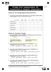
1
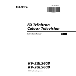
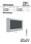
SERVICE MANUAL
MODEL
KV-28LS60B
KV-28LS60E
KV-28LS60U
AE-6B CHASSIS
COMMANDER
DEST
CHASSIS NO.
RM-932
FR
SCC-Q83C-A
RM-932
ESP
SCC-Q81E-A
RM-932
UK
SCC-Q84D-A
MODEL
KV-32LS60B
KV-32LS60E
KV-32LS60K
KV-32LS60U
COMMANDER
DEST
CHASSIS NO.
RM-932
FR
SCC-Q83B-A
RM-932
ESP
SCC-Q81D-A
RM-932
OIRT
SCC-Q82C-A
RM-932
UK
SCC-Q84C-A
KV-28/32LS60
RM-932
-1-
AE-6B SELF DIAGNOSTIC SOFTWARE
The identification of errors within the AE-6B chassis is triggered in one of two ways :- 1: Busy or 2: Device failure to respond to IIC. In the
event of one of these situations arising the software will first try to release the bus if busy (Failure to do so will report with a continuous
flashing LED) and then communicate with each device in turn to establish if a device is faulty. If a device is found to be faulty the relevant
device number will be displayed through the LED (Series of flashes which must be counted) See table 1, non fatal errors are reported using this
method.
Each time the software detects an error it is stored within the NVM. See Table 2.
Table 1
How to enter into Table 2
Error Message
No error
Reser ved
OCP ( Over Current Protection )
Over Voltage Protection
No Ver tical Sync
IKR Error at power on
IIC bus clock and/or data lines low at power on
NVM no IIC bus acknowledge at power on
Horizontal Protection
Tuner no acknowledge at power on
Sound Processor Error
Reser ved
Scanrate Error
DAC Error
Backend Error
Dynamic Convergence Error
PIP Error
LED
Code
00
01
02
03
04
05
06
07
08
09
10
11
12
13
14
15
16
1.
2.
3.
4.
5.
Table 2
ERROR MENU
E02
E03
E04
E05
E06
E07
E08
E09
E10
E11
E12
E13
E14
E15
E16
Flash Timing Example : e.g. error number 3
StBy LED
ON
ON
OFF
Turn on the main power switch of the TV set.
Program Remote Commander for Operation in Service
Mode. [See Page 22].
Press ‘VIDEO’ ‘VIDEO’ > ‘MENU’ on the Remote
Commander.
Using the Remote Commander, Scroll to the ‘Error Menu’
item using the down arrow key, then press the right arrow
key.
The following table will be displayed indicating the error
count.
OCP
OVP
VSYNC
IKR
IIC
NVM
HPROT
TUNER
SOUNDP
SCANRATE
DAC
BACKEND
DYN CON
PIP
(0, 255)
(0, 255)
(0, 255)
(0, 255)
(0, 255)
(0, 255)
(0, 255)
(0, 255)
(0, 255)
(0, 255)
(0, 255)
(0, 255)
(0, 255)
(0, 255)
(0, 255)
0
0
0
0
0
0
0
0
0
0
0
0
0
0
0
ON
WORKING TIME
HOURS
MINUTES
OFF
14
7
Note: To clear the error count data press ‘80’ on the Remote
commander.
-7-
SECTION 4 CIRCUIT ADJUSTMENTS
4-1. Electrical Adjustments
GEOMETRY
Service adjustments to this model can be performed using the
supplied remote Commander RM-932.
ABL TH
ABL MODE
P ABL
V SIZE
V POSITION
V COMP
V LIN
S CORRECTION
H SIZE
PIN AMP
UP CORNERPIN
M PIN
LO CORNERPIN
TRAPEZIUM
H POSITION
AFC BOW
AFC ANGLE
LEFT BLK
RIGHT BLK
V ASPECT
AKBTIM1
AKBTIM2
IKR
HNG
VNG
Programming the Remote Commander for
Operation in Service Mode
1.
Press the VCR/TV/DVD button until the
TV LED lights.
2.
Press and hold the yellow button for
approx. 5 seconds until the TV LED
flashes quickly.
3.
Press 99999. All three LED’s should light.
The remote commander is now set to Service Mode.
4.
To return the remote commander to normal operation mode
repeat steps 1. and 2. then press 00000. All three LED’s
should light.
The remote commander is now set to normal mode.
Setting the TV into Service Mode
1.
Program the remote commander for operation in Service
Mode as described above.
2.
Turn on the TV main power switch.
3.
Press the video standby button
on the remote
commander twice.
‘TT ’ will appear in the upper right corner of the screen.
Other status information will also be displayed.
4.
Press ‘MENU’ on the remote commander to obtain the
following menu on the screen.
AE6B v0.14 (Jun 2001)
Factory data FFh FFh
MSP Device : MSP3411G
6.
7.
·
3)
3)
15)
63)
63)
3)
15)
15)
63)
63)
63)
3)
63)
15)
63)
15)
15)
63)
63)
63)
3)
1)
0
0
15
35
33
1
7
7
44
32
29
2
29
2
40
8
9
34
17
47
2
0
1
0
0
DYN. CONV.
Geometry
Service
Scanrate
DAC
Dyn. Conv.
PiP
Sound
IF adjust
Error Menu
5.
(0,
(0,
(0,
(0,
(0,
(0,
(0,
(0,
(0,
(0,
(0,
(0,
(0,
(0,
(0,
(0,
(0,
(0,
(0,
(0,
(0,
(0,
Move to the corresponding adjustment item using the
up or down arrow buttons on the Remote Commander.
Press the right arrow button to enter into the required menu item.
Press the ‘Menu’ button on the Remote Commander to quit the
Service Mode when all adjustments have been completed.
Note :
·
After carrying out the service adjustments, to prevent the
customer accessing the ‘Service Menu’ switch the TV set
OFF and then ON.
- 22 -
RANGE
YupL
VAL
YlowL
VAL
MBOWupL
VAL
MBOWlowL
VAL
HAMPL
VAL
YupR
VAL
YlowR
VAL
MBOWupR
VAL
MBOWlowR
VAL
HAMPR
VAL
UP Y
VAL
LOW Y
VAL
H STAT
VAL
UP CORR
VAL
LOW CORR
VAL
(0, 63)
(0, 1)
(0, 63)
(0, 1)
(0, 63)
(0, 1)
(0, 63)
(0, 1)
(0, 63)
(0, 1)
(0, 63)
(0, 1)
(0, 63)
(0, 1)
(0, 63)
(0, 1)
(0, 63)
(0, 1)
(0, 63)
(0, 1)
(0, 63)
(0, 1)
(0, 63)
(0, 1)
(0, 63)
(0, 1)
(0, 63)
(0, 1)
(0, 63)
(0, 1)
(0, 63)
63
0
30
0
31
0
31
0
32
0
37
0
30
0
30
0
32
0
32
0
36
0
31
0
33
0
33
0
34
0
19
IF ADJUST
ERROR MENU
Automute
Audio Gain
L Gating
1
0
0
SERVICE
SUB COL
SUB HUE
SUB SHARP
SUB BRIGHT
SUB CONT
R-DRIVE
G-DRIVE
B-DRIVE
R CUTOFF
G CUTOFF
B CUTOFF
Br TXT
Br OSD
(0,
(0,
(0,
(0,
(0,
(0,
(0,
(0,
(0,
(0,
(0,
(0,
(0,
63)
63)
63)
63)
15)
63)
63)
63)
63)
63)
63)
15)
15)
OCP
OVP
VSYNC
IKR
IIC
NVM
HPROT
TUNER
SOUNDP
SCANRATE
DAC
BACKEND
DYN CON
PIP
E02
E03
E04
E05
E06
E07
E08
E09
E10
E11
E12
E13
E14
E15
E16
Adj
31
30
13
12
50
Adj
Adj
28
24
46
7
10
WORKING TIME
HOURS
MINUTES
(0,
(0,
(0,
(0,
(0,
(0,
(0,
(0,
(0,
(0,
(0,
(0,
(0,
(0,
(0,
255)
255)
255)
255)
255)
255)
255)
255)
255)
255)
255)
255)
255)
255)
255)
0
0
0
0
0
0
0
0
0
0
0
0
0
0
0
14
7
Sub Brightness Adjustment
1.
2.
DAC
CONFIG
MPIN CONT
HLIN
HTRAP
ROT. COIL
PHOCUS PH
3.
4.
00000000
(0,
(0,
(0,
(0,
(0,
255)
255)
255)
255)
255)
96
83
127
130
90
Sub Contrast Adjustment
1.
2.
3.
SOUND
M-N
M-D
M-S
S-M
D-M
N-M
BBE
B1
B2
B3
B4
B5
SW L
SW F
NICAM C AD
NICAM Error
Stereo
Status
4.
(0, 511)
(-128, -1)
(+0, +127)
(+0, +127)
(-128, -1)
(0, 1023)
(+0, +68)
(-96, +96)
(-96, +96)
(-96, +96)
(-96, +96)
(-96, +96)
(-128, +0)
(+5, +40)
200
-20
+20
+10
-10
496
+28
+0
+0
+0
+0
+0
+0
+30
Input a Monoscope pattern.
Program the Remote Commander for operation in Service Mode.
[ See Page 22 ].
Press ‘VIDEO’ ‘VIDEO’ 13 on the Remote Commander.
Adjust the ‘Sub-Brightness’ data so that there is barely a
difference between the 0 IRE and 10 IRE signal levels.
Input a video signal that contains a small 100% white area on a
black background.
Connect an digital voltmeter to Pin 10 of J7378 [C Board].
Program the Remote Commander for operation in Service Mode.
[ See Page 22 ].
Adjust the Sub-Contrast [ Using ‘VIDEO’ ‘VIDEO’ ‘11’ ] to
obtain a voltage of 105 +/- 5V.
Sub Colour Adjustment
1.
2.
3.
4.
Receive a PAL colour bar signal.
Connect an oscilloscope to Pin 6 of CN7001 [A Board].
Program the Remote Commander for operation in Service Mode.
[ See Page 22 ].
Adjust the ‘Sub Colour’ [ Using ‘VIDEO’ ‘VIDEO’ ‘12’ ] so
that the Cyan, Magenta and Blue colour bars are of equal levels
as indicated below.
10001
(0, 2047)
(-128, +127)
0
+0
Same Level
0000000110
B-Out Waveform
- 23 -
Deflection System Adjustment
1.
2.
4-2. TEST MODE 2:
Program the Remote Commander for operation in Service Mode.
[ See Page 22 ] and enter into the ‘Geometry’ service menu.
Select and adjust each item in order to obtain the optimum image.
V SIZE
V LIN
Test Mode 2 is available by rogramming the Remote Commander for
operation in Service Mode [ As shown on Page 22 ] then pressing the
‘VIDEO’ button twice, OSD ‘TT’ appears. The functions described
below are available by selecting the two numbers. To release the ‘Test
mode 2’, press 00, 10, 20 ... twice or switch the TV set into Stand-by
mode. In ‘TT Menu’ mode, it is possible to remove the Menu from
the screen by pressing the Speaker Off button once. Pressing the
Speaker OFF button a second time will cause the Menu to reappear.
The function is kept even when the menu is not displayed on
screen !!.
AFC BOW
V POSITION
H POSITION
H SIZE
PIN AMP
TRAPEZIUM
UP CORNER PIN
AFC ANGLE
LO CORNER PIN
GEOMETRY
ABL TH
ABL MODE
P ABL
V SIZE
V POSITION
V COMP
V LIN
S CORRECTION
H SIZE
PIN AMP
UP CORNERPIN
M PIN
LO CORNERPIN
TRAPEZIUM
H POSITION
AFC BOW
AFC ANGLE
LEFT BLK
RIGHT BLK
V ASPECT
AKBTIM1
AKBTIM2
IKR
HNG
VNG
(0,
(0,
(0,
(0,
(0,
(0,
(0,
(0,
(0,
(0,
(0,
(0,
(0,
(0,
(0,
(0,
(0,
(0,
(0,
(0,
(0,
(0,
3)
3)
15)
63)
63)
3)
15)
15)
63)
63)
63)
3)
63)
15)
63)
15)
15)
63)
63)
63)
3)
1)
0
0
15
35
33
1
7
7
44
32
29
2
29
2
40
8
9
34
17
47
2
0
1
0
0
- 24 -
00
01
02
03
04
05
06
07
08
11
12
13
14
15
16
19
21
22
23
24
25
26
'TT' mode off
Picture maximum
Picture minimum
Set speaker/headphone Volume
Set speaker/headphone Volume
Set speaker/headphone Volume
Set speaker/headphone Volume
Ageing mode
Shipping Condition
Sub picture adjustment
Sub colour adjustment
Sub Brightness adjustment
Text H Position adjustment
Rotation Coil Test
Picture level 50%
Factory Mode Enable/Disable
Destination ADEKR
Destination BL
Destination ADEKR
Destination U
Destination ADEKR
Destination BL
27
28
31
36
41
43
44
45
46
48
49
53
55
59
68
73
74
78
79
87
99
Destination ADEKR
Destination ADEKR
Auto Shutoff Enable/Disable
Velocity Modulation (VM) OFF/ON test
Re-initialise NVM
Select Dual A sound
Select Dual B sound
Select Mono sound
Select Stereo sound
Set NVM as non virgin
Set NVM as virgin
FM Overmodulation Enable/Disable
Tuner selection (SONY/ALPS)
Select Model 3 Scar ts + PIP or 2 Scar ts
Enable/Disable X26 countermeasure (N problem)
Enable Zweiton D/K2 system (6.5/6.74)
Enable Zweiton D/K3 system (6.5/5.74)
Balance full right
Balance full left
Local keys test
Display Error and Working Time menu
to
to
to
to
35%
50%
65%
80%
~ A Schematic [ Video & Audio Processors, Audio Output,
Vertical Deflection] page 1/2~
29 --- 29
~ A Board Waveforms ~
5ms/div
TP1
2ms/div
TP2
744 mVp-p (V)
53 Vp-p (V)
10us/div
20us/div
TP4
TP4
TP3
1.4 Vp-p (H)
688 mVp-p (H)
5ms/div
5ms/div
TP5
TP6
264 mVp-p (H)
272 mVp-p (H)
~ A Board Difference Table ~
Ref
28LS60B
28LS60E
28LS60U
32LS60B
32LS60E
32LS60K
32LS60U
C1011
120PF 5% 50V
_
_
120PF 5% 50V
_
_
_
C1012
56PF 5% 50V
_
_
56PF 5% 50V
_
_
_
C1016
10PF 0.50PF 50V
_
_
10PF 0.50PF 50V
_
_
_
C1017
68PF 5% 50V
_
_
68PF 5% 50V
_
_
_
L1004
18UH
_
_
18UH
_
_
_
Q1002
MSD601-RST1
_
_
MSD601-RST1
_
_
_
Q1003
DTC114EK
_
_
DTC114EK
_
_
_
R1011
330 5% 1/10W
_
_
330 5% 1/10W
_
_
_
R1012
330 5% 1/10W
_
_
330 5% 1/10W
_
_
_
R1014
_
SHORT 0
SHORT 0
_
SHORT 0
SHORT 0
SHORT 0
R1015
470 5% 1/10W
_
_
470 5% 1/10W
_
_
_
R1016
100 5% 1/10W
_
_
100 5% 1/10W
_
_
_
R1018
2.2K 5% 1/10W
_
_
2.2K 5% 1/10W
_
_
_
R1020
SHORT 0
_
_
SHORT 0
_
_
_
R5303
56K 0.5% 1/10W
56K 0.5% 1/10W
56K 0.5% 1/10W
27K 0.5% 1/10W
27K 0.5% 1/10W
27K 0.5% 1/10W
27K 0.5% 1/10W
R5306
6.8K 0.5% 1/10W
6.8K 0.5% 1/10W
6.8K 0.5% 1/10W
7.5K 0.5% 1/10W
7.5K 0.5% 1/10W
7.5K 0.5% 1/10W
7.5K 0.5% 1/10W
R5327
82 5% 3W
82 5% 3W
82 5% 3W
39 5% 3W
39 5% 3W
39 5% 3W
39 5% 3W
R5338
1K 5% 1/4W
1K 5% 1/4W
1K 5% 1/4W
470 5% 1/4W
470 5% 1/4W
470 5% 1/4W
470 5% 1/4W
R5400
180K 5% 1/10W
180K 5% 1/10W
180K 5% 1/10W
220K 5% 1/10W
220K 5% 1/10W
220K 5% 1/10W
220K 5% 1/10W
R5407
560K 5% 1/10W
560K 5% 1/10W
560K 5% 1/10W
1M 5% 1/10W
1M 5% 1/10W
1M 5% 1/10W
1M 5% 1/10W
R5878
820 5% 1/10W
820 5% 1/10W
820 5% 1/10W
1K 5% 1/10W
1K 5% 1/10W
1K 5% 1/10W
1K 5% 1/10W
R5883
2.2M 5% 1/10W
2.2M 5% 1/10W
2.2M 5% 1/10W
680K 5% 1/10W
680K 5% 1/10W
680K 5% 1/10W
680K 5% 1/10W
BTF-EF411
BTF-EC411
BTF-EU611
BTF-EF411
BTF-EC411
BTF-EC411
BTF-EU611
TU1000
~ A Schematic [ Video & Audio Processors, Audio Output,
Vertical Deflection] page 2/2~
30 --- 30
~ VM Printed Wiring Board Conductor side ~
~ VM Board Waveforms ~
TP3
TP2
1.54 Vp-p (H)
Ref
5ms/div
5ms/div
5ms/div
TP1
~ VM Board Voltage Table ~
1.4 Vp-p (H)
20 Vp-p (H)
(e)(s) (b)(g) (c)(d)
Q7400
5.0
5.7
Q7401
0.9
1.5
8.7
4.1
Q7402
5.5
6.1
8.9
Q7403
5.1
5.5
8.9
Q7404
4.7
4.1
0
Q7405
5.1
4.7
0
Q7406
134
133.8
68
Q7407
1.1
1.4
68
Q7408
6.3
5.6
2.5
Q7409
5.7
6.3
0.9
~ A Board Location Table (A Side) ~
D2014
K-9
D3005
M-7
D3017
M-4
D3028
M-2
D5306
C-5
D7004
F-7
IC5301
D-4
IC6206
H-3
M-7
D2015
K-9
D3007
M-7
D3018
N-3
D3201
J-2
D5307
C-6
D5809
K-8
IC5302
B-4
IC6207
H-4
D0104
L-4
D2018
M-2
D3008
M-7
D3019
N-3
D5103
D-6
D5400
E-4
IC5400
G-4
D0110
I-4
D2019
M-2
D3009
N-7
D3021
M-4
D5104
E-5
D5404
F-3
IC5104
D-6
IC6201
G - 10
Q5202
D0111
H-2
D2502
H-9
D3011
M-4
D3023
M-4
D5200
D-2
D5405
F-3
IC5200
B-3
IC6202
I-6
Q5301
C-5
D0112
M-4
D3001
M-7
D3013
M-4
D3024
M-4
D5201
E-2
D5807
F-7
IC5201
C-4
IC6203
J-6
Q5306
E-4
D0113
M-5
D3003
M-7
D3015
M-4
D3026
M-2
D5305
D-6
D6200
J-6
IC5300
E-4
IC6205
D-5
Q5404
F-4
D1006
M - 10
DIODE
D0101
IC
TRANSISTOR
E-2
~ A Board Location Table (B Side) ~
D2503
G-9
D3024
B-3
D5309
J-3
IC5103
L-3
Q3201
C-2
Q5300
M-4
Q7003
H-6
D0101
B-7
D3001
B-7
D3026
B-2
D5400
K-4
IC5104
K-6
Q1000
C-6
Q3202
C-3
Q5301
L-5
Q7009
K-6
D0104
C-5
D3003
B-7
D3028
C-2
D5401
J-4
IC5200
M-3
Q1001
D-6
Q3204
C-3
Q5302
K-7
Q7011
J-6
D0110
G-4
D3005
B-7
D3201
F-2
D5404
J-3
IC5201
L-4
Q1004
D - 10
Q3300
F-3
Q5303
M-4
Q7012
J-5
D0111
G-2
D3007
B-6
D5103
L-6
D5405
I-3
IC5300
J-3
Q1005
B-2
Q3301
F-3
Q5304
M-5
Q7013
J-6
D0112
C-5
D3008
B-6
D5104
J-5
D5809
K-8
IC5301
K-4
Q1006
B-3
Q3302
F-3
Q5305
K-3
Q7014
J-6
DIODE
TRANSISTOR
D0113
C-5
D3009
B-6
D5200
K-2
D5811
L-8
IC5302
M-4
Q2000
C-9
Q3500
F-3
Q5306
K-4
Q7015
I-5
D1006
B - 10
D3011
C-4
D5202
L-4
D5812
L-8
IC5400
I-3
Q2002
D-9
Q3501
F-3
Q5400
J-4
Q7016
I-5
D6200
F-7
IC6200
I-9
Q2003
D-9
Q5101
M-5
Q5401
K-4
Q7017
I-6
IC6201
I-8
Q2004
E-7
Q5200
M-4
Q5402
J-5
Q7018
I-5
IC6202
F-6
Q2005
E-7
Q5201
N-3
Q5403
J-4
Q7019
I-5
D2014
C-9
D3013
C-4
D5300
L-5
D2015
D-9
D3015
C-4
D5303
N-4
D2016
E-8
D3017
B-4
D5304
M-4
IC
IC2000
C-8
D2018
B-2
D3018
B-3
D5305
L-6
IC2001
D-9
IC6203
E-6
Q2501
G-8
Q5202
K-3
Q5404
J-4
D2019
B-2
D3019
B-3
D5306
L-5
IC2500
F-8
IC6205
K-5
Q2502
G-9
Q5203
J-2
Q5813
J-8
D2500
G-9
D3021
C-4
D5307
L-7
IC3100
E-5
IC6206
G-3
Q2503
G-9
Q5204
L-4
Q5815
L-8
D2502
G-9
D3023
B-3
D5308
M-4
IC3200
E-3
IC6207
G-4
Q3200
C-3
Q5205
M-3
Q5816
L-8
- 33 -
~ A Board Semiconductor Voltage Table ~
Ref
(s)
(g)
(d)
Ref
(e)
(b)
(c)
Ref
(e)
(b)
(c)
Ref
(e)
(b)
(c)
Ref
(e)
(b)
(c)
Ref
(e)
(b)
(c)
Q3500
2.7
3.3
3.9
Q2002
0
0
4
Q3204
5
4.4
3.4
Q5205
1.9
1.2
0
Q5813
0
7.9
0
Q7015
11.6
10.9
8.8
Q3501
2.7
3.3
4
Q2003
0
0
4
Q3300
0.7
1.3
5
Q5300
0
0.4
2.2
Q5814
0
0
0
Q7016
6
6.6
10.9
Q5301
0
5.1
51.2
Q2004
3.3
3.9
8.3
Q3301
1.9
1.2
0
Q5301
5.1
0
51.2
Q5815
0
0
5
Q7017
2.7
2
0
Q5404
0
0
0.5
Q2005
3.3
3.9
8.3
Q3302
1.9
1.2
0
Q5302
8.9
5.7
0
Q5816
5
5
0
Q7018
11.6
10.9
8.6
Ref
(e)
(b)
(c)
Q2501
0
0
15.2
Q3500
3.3
2.7
3.9
Q5304
0
0. 4
5.6
Q7003
5.6
6.2
8.8
Q7019
6
6.6
10.9
Q1001
3.2
3.9
8.3
Q2502
0
0.7
0
Q3501
3.3
2.7
4
Q3400
0
0
0. 1
Q7009
3.2
7
0. 1
Q7020
8.9
8.9
0
Q1004
1.9
1.3
0
Q2503
0.6
0.6
0.5
Q5101
0
0.4
6.4
Q5401
0
0
7. 9
Q7011
2.5
1.9
0
Q7021
2.7
2.7
8.9
Q1005
0
0. 5
5
Q3200
1.9
2.5
4.4
Q5201
2.8
3.4
7.9
Q5402
0
0
-11.3
Q7012
11.6
10.9
8.7
Q1006
5
4.7
1
Q3201
1.9
2.5
4.4
Q5202
0.2
0.8
11.7
Q5403
-13.5
-11.2
-8.3
Q7013
6
6. 6
10.9
Q2000
4.2
4.8
8.3
Q3202
5
4.4
3.4
Q5203
0.2
0.8
11.7
Q5404
0
0
0.5
Q7014
2.5
1.8
0
~ A Board IC Voltage Table ~
IC Voltage Table
Ref No
Ref No
Pin No Voltage (V)
Ref No
Pin No
Voltage (V)
Pin No
Voltage (V)
1
1.3
6
1.8
5
9.3
2
1.7
7
2
6
3
2.6
8
0
Ref No
Ref No
Pin No
Voltage (V)
Pin No
Voltage (V)
6
13.7
32
8.9
0.5
7
1.4
33
0
7
12.1
1
3.6
34
4.7
IC5400
IC5201
4
0
9
3.1
8
-14.1
2
0
35
4.7
5
2.5
10
3
1
6
3
4.4
36
4.7
8.9
IC5103
6
3.3
11
5
2
6
4
4.8
37
7
0
12
5
3
6
5
3.5
38
0
8
0
13
5
4
0
6
3.4
39
4.8
9
1.1
14
0
5
6
7
7.6
40
4.8
10
1.1
15
0
6
6
8
0
41
4.8
0
IC5300
11
0
16
5
7
6
9
0
42
12
0
1
4.8
8
12
10
0.4
43
0
13
0
2
4.9
1
1.7
11
1.8
44
0
14
0
3
4.8
2
8.5
12
0.4
45
6.3
15
0.5
4
4.8
3
6.5
13
0.9
46
8.9
16
0.3
5
5
4
0
14
5
47
8.9
17
0.3
6
5
5
6.5
15
2.5
48
6
18
0.3
7
5
6
7.1
16
0
49
2.5
19
3.3
8
5
7
0.4
17
3
50
4.1
IC3100
IC5301
20
0
21
3.3
IC7002
IC7002
9
4.9
8
12
18
2.7
51
0
10
12.1
1
0
19
3.9
52
6
IC5200
22
3.3
11
4.1
2
5.8
20
0
53
5.8
23
0
12
5
3
6.3
21
6.1
54
5.8
24
3.2
13
5
4
0
22
2.7
55
0.4
25
1.2
14
1.9
5
6.6
23
8.8
56
5.8
26
3.2
15
1.1
6
6.5
24
0
57
5.8
27
2.1
16
0
7
0.4
25
4.3
58
5.8
28
0.3
17
0
8
12
26
3.2
59
0.3
0
IC5302
IC5103
1
3.3
18
0
1
1.4
27
5.2
60
2
3.3
1
9.3
2
13.2
28
0.3
61
0
3
1.9
2
3.8
3
-12.5
29
4.9
62
2.9
4
2.6
3
3.8
4
-15.4
30
3.4
63
3.7
5
2.5
4
-15.4
5
-0.4
31
5.6
IC5400
IC5201
- 34 -
A
1
B
C
D
E
F
G
H
~ F2 Board Schematic Diagram [ Power Switch & Fuse. LED & IR Receiver ] ~
J
K
L
M
~ H2 Board Schematic Diagram [ Front AV & Headphone ] ~
2
3
4
5
6
7
8
9
10
11
I
~ VM Board Schematic Diagram [ Velocity Modulation ] ~
- 35 -
N
A
B
C
D
E
F
G
H
I
J
K
L
M
N
1
2
3
4
5
6
7
8
9
10
~ G Board Schematic Diagram [ Power Supply ] ~
11
- 37 -
A
B
C
D
E
F
G
H
I
J
K
L
M
N
1
2
3
4
5
6
7
8
9
10
~ C Board Schematic Diagram [ R-G-B Out ] ~
11
- 38 -
~ C Printed Wiring Board Conductor side ~
~ M Printed Wiring Board Conductor side A ~
~ C Board Waveforms ~
10us/div
10us/div
TP2
TP1
2.16 Vp-p (H)
2.0 Vp-p (H)
10us/div
10us/div
TP4
TP4
TP3
~ M Printed Wiring Board Conductor side B ~
6.8 Vp-p (H)
1.9 Vp-p (H)
10us/div
10us/div
TP5
~ C Board Semiconductor Voltage Table ~
Ref
(e)
(b)
(c)
Q7350
12
11.98
0
~ C Board IC Voltage Table ~
IC Voltage Table
Ref No Pin No Voltage (V)
Q7352
0
0
3.8
Q7353
0
0
3.8
1
3.9
Q7354
11.98
12
0
3
3.8
3.8
5
7.5
6
200
Q7355
0
0
TP6
IC7300
IC7325
IC7350
7
140
8
153
9
140
1
3.9
3
3.8
5
7.7
6
200
7
140
8
153
9
140
1
3.9
3
3.8
5
7.5
6
200
7
139
8
148
9
138
116 Vp-p (H)
100 Vp-p (H)
10us/div
TP7
100 Vp-p (H)
- 39 -
A
B
C
D
E
F
G
H
I
J
K
L
M
N
1
2
3
4
5
6
7
8
9
10
~ M Board Schematic Diagram [ Micro• Processor ] ~
11
- 40 -
A
B
C
D
E
F
G
H
I
J
K
L
M
N
1
2
3
4
5
6
7
8
9
10
~ D Board Schematic Diagram [ Deflection ] ~
11
- 42 -
~ D Board Difference Table ~
Ref
28LS60B
28LS60E
28LS60U
32LS60B
32LS60E
32LS60K
32LS60U
C8107
-
-
-
27K 0.5% 1/10W
27K 0.5% 1/10W
27K 0.5% 1/10W
27K 0.5% 1/10W
C8130
220PF 5% 50V
220PF 5% 50V
220PF 5% 50V
_
_
_
_
C8207
_
_
_
0.047UF 10% 16V
0.047UF 10% 16V
0.047UF 10% 16V
0.047UF 10% 16V
C8208
_
_
_
0.01UF 10% 25V
0.01UF 10% 25V
0.01UF 10% 25V
0.01UF 10% 25V
C8814
7500PF 3% 1.2KV
7500PF 3% 1.2KV
7500PF 3% 1.2KV
6800PF 3% 1.2KV
6800PF 3% 1.2KV
6800PF 3% 1.2KV
6800PF 3% 1.2KV
C8815
6800PF 3% 1.5KV
6800PF 3% 1.5KV
6800PF 3% 1.5KV
6200PF 3% 1.5KV
6200PF 3% 1.5KV
6200PF 3% 1.5KV
6200PF 3% 1.5KV
C8825
0.22UF 5% 250V
0.22UF 5% 250V
0.22UF 5% 250V
0.18UF 5% 250V
0.18UF 5% 250V
0.18UF 5% 250V
0.18UF 5% 250V
C8826
0.68UF 5% 250V
0.68UF 5% 250V
0.68UF 5% 250V
0.56UF 5% 250V
0.56UF 5% 250V
0.56UF 5% 250V
0.56UF 5% 250V
R8127
4.7K 0.5% 1/10W
4.7K 0.5% 1/10W
4.7K 0.5% 1/10W
6.8K 0.5% 1/10W
6.8K 0.5% 1/10W
6.8K 0.5% 1/10W
6.8K 0.5% 1/10W
R8141
22K 0.5% 1/10W
22K 0.5% 1/10W
22K 0.5% 1/10W
33K 0.5% 1/10W
33K 0.5% 1/10W
33K 0.5% 1/10W
33K 0.5% 1/10W
R8142
7.5K 0.5% 1/10W
7.5K 0.5% 1/10W
7.5K 0.5% 1/10W
4.7K 0.5% 1/10W
4.7K 0.5% 1/10W
4.7K 0.5% 1/10W
4.7K 0.5% 1/10W
R8144
220K 5% 1/10W
220K 5% 1/10W
220K 5% 1/10W
120K 5% 1/10W
120K 5% 1/10W
120K 5% 1/10W
120K 5% 1/10W
R8149
22K 5% 1/10W
220K 5% 1/10W
220K 5% 1/10W
3.9K 5% 1/10W
3.9K 5% 1/10W
3.9K 5% 1/10W
3.9K 5% 1/10W
R8150
22K 5% 1/10W
22K 5% 1/10W
22K 5% 1/10W
6.8K 5% 1/10W
6.8K 5% 1/10W
6.8K 5% 1/10W
6.8K 5% 1/10W
R8154
5.6K 5% 1/10W
5.6K 5% 1/10W
5.6K 5% 1/10W
3.3K 5% 1/10W
3.3K 5% 1/10W
3.3K 5% 1/10W
3.3K 5% 1/10W
R8155
4.7K 0.5% 1/10W
4.7K 0.5% 1/10W
4.7K 0.5% 1/10W
2.7K 5% 1/10W
2.7K 5% 1/10W
2.7K 5% 1/10W
2.7K 5% 1/10W
R8158
2.2K 0.5% 1/10W
2.2K 0.5% 1/10W
2.2K 0.5% 1/10W
4.7K 0.5% 1/10W
4.7K 0.5% 1/10W
4.7K 0.5% 1/10W
4.7K 0.5% 1/10W
R8159
2.2K 0.5% 1/10W
2.2K 0.5% 1/10W
2.2K 0.5% 1/10W
SHORT 0
SHORT 0
SHORT 0
SHORT 0
R8161
6.8K 0.5% 1/10W
6.8K 0.5% 1/10W
6.8K 0.5% 1/10W
8.2K 0.5% 1/10W
8.2K 0.5% 1/10W
8.2K 0.5% 1/10W
8.2K 0.5% 1/10W
R8175
4.7K 5% 1/10W
4.7K 5% 1/10W
4.7K 5% 1/10W
6.8K 5% 1/10W
6.8K 5% 1/10W
6.8K 5% 1/10W
6.8K 5% 1/10W
R8176
SHORT 0
SHORT 0
SHORT 0
10K 5% 1/10W
10K 5% 1/10W
10K 5% 1/10W
10K 5% 1/10W
R8177
5.6K 5% 1/10W
5.6K 5% 1/10W
5.6K 5% 1/10W
4.7K 5% 1/10W
4.7K 5% 1/10W
4.7K 5% 1/10W
4.7K 5% 1/10W
R8179
4.7K 5% 1/10W
4.7K 5% 1/10W
4.7K 5% 1/10W
SHORT 0
SHORT 0
SHORT 0
SHORT 0
R8186
2.7K 5% 1/10W
2.7K 5% 1/10W
2.7K 5% 1/10W
3.9K 5% 1/10W
3.9K 5% 1/10W
3.9K 5% 1/10W
3.9K 5% 1/10W
R8189
1.5K 5% 1/10W
1.5K 5% 1/10W
1.5K 5% 1/10W
560 5% 1/10W
560 5% 1/10W
560 5% 1/10W
560 5% 1/10W
R8203
6.8K 5% 1/10W
6.8K 5% 1/10W
6.8K 5% 1/10W
SHORT 0
SHORT 0
SHORT 0
SHORT 0
R8206
470K 5% 1/10W
470K 5% 1/10W
470K 5% 1/10W
330K 0.5% 1/10W
330K 0.5% 1/10W
330K 0.5% 1/10W
330K 0.5% 1/10W
R8207
270K 5% 1/10W
270K 5% 1/10W
270K 5% 1/10W
220K 5% 1/10W
220K 5% 1/10W
220K 5% 1/10W
220K 5% 1/10W
R8215
22K 0.5% 1/10W
22K 0.5% 1/10W
22K 0.5% 1/10W
47K 0.5% 1/10W
47K 0.5% 1/10W
47K 0.5% 1/10W
47K 0.5% 1/10W
R8216
47K 5% 1/10W
47K 5% 1/10W
47K 5% 1/10W
47K 0.5% 1/10W
47K 0.5% 1/10W
47K 0.5% 1/10W
47K 0.5% 1/10W
R8220
6.8K 5% 1/10W
6.8K 5% 1/10W
6.8K 5% 1/10W
12K 5% 1/10W
12K 5% 1/10W
12K 5% 1/10W
12K 5% 1/10W
R8221
18K 5% 1/10W
18K 5% 1/10W
18K 5% 1/10W
22K 5% 1/10W
22K 5% 1/10W
22K 5% 1/10W
22K 5% 1/10W
R8224
_
_
_
3.3K 5% 1/10W
3.3K 5% 1/10W
3.3K 5% 1/10W
3.3K 5% 1/10W
R8810
4.7K 5% 2W
4.7K 5% 2W
4.7K 5% 2W
3.9K 5% 2W
3.9K 5% 2W
3.9K 5% 2W
3.9K 5% 2W
R8836
18K 5% 1/4W
18K 5% 1/4W
18K 5% 1/4W
15K 5% 1/4W
15K 5% 1/4W
15K 5% 1/4W
15K 5% 1/4W
R8856
8.2K 5% 3W
8.2K 5% 3W
8.2K 5% 3W
6.8K 5% 3W
6.8K 5% 3W
6.8K 5% 3W
6.8K 5% 3W
R8857
8.2K 5% 3W
8.2K 5% 3W
8.2K 5% 3W
6.8K 5% 3W
6.8K 5% 3W
6.8K 5% 3W
6.8K 5% 3W
R8858
8.2K 5% 3W
8.2K 5% 3W
8.2K 5% 3W
6.8K 5% 3W
6.8K 5% 3W
6.8K 5% 3W
6.8K 5% 3W
R8859
8.2K 5% 3W
8.2K 5% 3W
8.2K 5% 3W
6.8K 5% 3W
6.8K 5% 3W
6.8K 5% 3W
6.8K 5% 3W
R8886
220K 0.5% 1/10W
220K 0.5% 1/10W
220K 0.5% 1/10W
220K 5% 1/10W
220K 5% 1/10W
220K 5% 1/10W
220K 5% 1/10W
R8897
470K 1% 1/4W
470K 1% 1/4W
470K 1% 1/4W
680K 1% 1/4W
680K 1% 1/4W
680K 1% 1/4W
680K 1% 1/4W
T8800
FBT ASSY
NX4522//Z214
FBT ASSY
NX4522//Z214
FBT ASSY
NX4522//Z214
FBT ASSY
NX4522//Z2B4
FBT ASSY
NX4522//Z2B4
FBT ASSY
NX4522//Z2B4
FBT ASSY
NX4522//Z2B4
- 43 -
5-4. SEMICONDUCTORS
CXAB070AP
MCZ3001D
10
18
7
8
1
PST573IMT
LM318P
LM358N
LM393DT
LM393N
M24C16-MN6T(A)
6
1
3
5
2
9
1 Vcc
+
2
1
3
3 Out
2 Gnd
4
CXA1875AM-T4
SAA5665HL/M1D/0358
LM78L05ACZ
16
9
100
76
1
1
75
8
( TOP VIEW )
51
25
IN
GND
OUT
26
50
CXA2100AQ-TL
SBX3081-51(30)
MSP3411G-QA-B10
51
33
9
1
68
61
32
52
64
20
1
10
60
18
52
26
44
19
(TOP VIEW)
27
35
43
( TOP VIEW )
SDA9488X-B23GEG
K6T2008V2A-YF70T00
1
16
32
NJM3404AD-W
UPC4558G2
8
5
1
4
1
28
14
15
17
( TOP VIEW )
LA6500-FA
PQ30RV11
STV9379
1
2
3
4
:
:
:
:
1
2
3
4
V IN
V OUT
GND
ON/OFF CONTROL
- 44 -
1
7
TCET1103G
DTA144EK
DTC144TKA-T146
2SA1162-G
SE135N-LF4
C
E
B
3
2
1
TDA6111Q/N4
DTA144ESA
2SA933AS-QT
2SC2785-HFE
2SA1837(LBS2S0N)
1
9
E
B
C
B
C
E
TDA7497
L7809CV/LSY
STP5NB40FP
STP5NB40(030Y)
2SC5698-CA
2S5696-SONY-CA
1
2SB734-34
15
1
2
3
VPS9402-A32GEG
2SC2688(5)-LK
80
61
1
60
20
MSB709-RT1
MSD601-RST1
M1MA152WA-T1
UN2111
UN213
2SK2036(TE85L)
41
21
40
(TOP VIEW)
E
C
BA12T
BAO33T
IRF614-005
IRF620
SPA07N60C2
2SA2005
2SC5511
BAS216
RB705D
3
1
2
2
3
1
B
C
E
- 45 -
B
1 V OUT SENSE
2 COLLECTOR
3 GND
BAS316-115
MMDL914T1
UDZSTE-176.2B
FBIU4D7MA-B
RBV-406B
S1VB40
ANODE
CATHODE
BYV98-200-RAS 15/12
CATHODE
GS1B460/45
ANODE
D1NL20U
EGP20G
EL1Z
GP08D
UF4005PKG23
CATHODE
TLHK5190
ANODE
CATHODE
ANODE
D2S4MTA1
ERA38-06
ERA85-009
HZS9.1NB2
MTZJ-13B
MTZJ-33B
MTZJ-3.6A
MTZJ-4.7C
MTZJ-T-77-22
RD15ES-B2
RD39ES-B2
RD5.6ESB2
1SS119-25
1SS133T-77
CATHODE
ANODE
- 46 -
5-5 IC BLOCK DIAGRAMS
A BOARD IC6202/IC6205 BA033T/BA12T
1
REFERENCE
VOLTAGE
+
3
2
A BOARD IC2500 TDA7497
2
VOLUME
1
14
30K
OP AMP
9
MUTE/STBY
PROTECTIONS
10
VOLUME
60K
5
12
30K
OP AMP
3
4
G BOARD IC6001 MCZ3001D
18
8
Remote
OFF
Sel=34v
Internal
ref 5v
DVLD
15v/8v
TSD
Driver
Reg. 10v
14
Level
Shift
1
16
Vsense
15
Control
Logic
Latch
10
Centre
12
Osc
SS
11
F/B
Timer
OCP
5
7
4
3
2
6
- 47 -
9
A BOARD IC2000 MSP3411G
65
3
68
1
5
4
SBUS Interface
25
6
I2C Interface
DEMODULATOR
23
7
D/A
56
D/A
57
D/A
59
D/A
60
D/A
47
D/A
48
IDENT
28
DFP
31
A/D
30
A/D
34
33
37
50
SCART Switching Facilities
36
G BOARD IC6003 SE135N-LF4
5
4
51
A BOARD IC5301/IC5302 LM393N
3
1
1
+
7
-
-
+
2
3
6
5
9
8
7
6
2
A BOARD IC5400 STV9379
2
6
A BOARD IC5300 LM358N
3
FLYBACK
GENERATOR
1
8
2
7
- +
POWER
AMPLIFIER
7
1
+
+-
3
6
4
5
5
THERMAL
PROTECTION
4
- 48 -
SECTION 6
EXPLODED VIEWS
NOTE :
Items with no part number and no description are not
stocked because they are seldom required for routine
service.
The construction parts of an assembled part are indicated
with a collation number in the remarks column.
Items marked “*” are not stocked
since they are seldom required for
routine service. Some delay should
be anticipated when ordering these
items.
6-1. CHASSIS
17
21
18
19
13
14
12
11
20
10
15
9
16
15
16
8
2
7
4
3
5
6
UK Models
only
1
REF.NO.
1
2
3
4
£
5
6
£
PART.NO
*A-1647-043-A
*A-1624-102-A
*4-206-055-01
1-571-433-21
*4-202-531-01
1-823-853-11
£
1-776-860-12
7
8
9
10
11
12
1-424-855-11
*4-206-106-01
*A-1300-179-A
8-598-535-11
8-598-533-01
8-598-529-01
*A-1300-287-A
*A-1300-302-A
*A-1300-175-A
DESCRIPTION
REMARK
H2 BOARD, COMPLETE
F2 BOARD, COMPLETE
BRACKET F2
SWITCH, PUSH (AC POWER)
AC CORD LOCK (SC)
CORD, POWER (KV-28LS60B/28LS60E/32LS60B/
KV-32LS60E/32LS60K)
POWER CORD, FILTER (UK)
(KV-28LS60U/32LS60U)
COIL, CHOKE 29MMH
BRACKET, MAIN
G BOARD, COMPLETE
FRONTEND BTF-EF411 (KV-28LS60B/32LS60B)
FRONTEND BTF-EC411 (KV-28LS60E/32LS60E
/32LS60K)
FRONTEND BTF-EU611 (KV-28LS60U/32LS60U)
M BOARD, COMPLETE
A BOARD, COMPLETE (KV-28LS60B)
A BOARD, COMPLETE (KV-28LS60E)
REF.NO.
13
14
15
16
17
18
19
20
21
- 49 -
£
PART.NO
*A-1300-301-A
*A-1300-288-A
*A-1300-177-A
*A-1300-289-A
1-453-383-21
£
1-453-340-31
*A-1300-176-A
*A-1300-178-A
7-685-663-71
1-529-408-11
*A-1678-219-A
7-685-663-71
1-529-989-11
4-206-089-11
4-206-062-21
7-685-663-79
DESCRIPTION
A BOARD, COMPLETE
A BOARD, COMPLETE
A BOARD, COMPLETE
A BOARD, COMPLETE
TRANSFORMER ASSY,
REMARK
(KV-28LS60U)
(KV-32LS60B)
(KV-32LS60E/32LS60K)
(KV-32LS60U)
FLYBACK (NX-4522//Z214)
(KV-28LS60)
TRANSFORMER ASSY, FLYBACK (NX-4522//Z2B4)
(KV-32LS60)
D BOARD, COMPLETE (KV-28LS60)
D BOARD, COMPLETE (KV-32LS60)
SCREW +BVTP 4x16 TYPE 2 IT-3
SPEAKER (4.2x24CM)
WOOFER COMPL. ASSY
18-19
SCREW +BVTP 4x16 TYPE 2 IT-3
SPEAKER (8CM)
COVER REAR (KV-28LS60)
COVER REAR (KV-32LS60)
SCREW +BVTP 4x16 TYPE 2 IT-3
6-2. PICTURE TUBE
67
73
66
74
75
76
77
72
68
69
71
66
70
65
63
62
64
61
60
59
55
58
54
52
51
53
57
56
REF.NO.
51
52
53
54
55
56
57
58
59
60
61
62
63
64
£
£
PART.NO
X-4039-915-1
X-4200-824-1
4-205-948-02
4-204-426-01
4-205-375-01
4-204-295-01
X-4200-712-3
X-4039-993-1
4-205-946-02
4-047-464-01
8-451-521-11
1-451-480-11
1-419-363-11
8-453-011-11
*A-1644-119-A
*A-1638-158-A
4-369-318-21
DESCRIPTION
REMARK
BEZNET ASSY (KV-28LS60) 52-55
BEZNET ASSY (KV-32LS60)
POWER BUTTON
SPRING
GUIDE, LIGHT
SHEET, BLOTTING
57-58
DOOR ASSY (KV-28LS60)
DOOR ASSY (KV-32LS60)
DOOR
CATCHER, PUSH
DEFLECTION YOKE (Y28RVC3-B)(KV-28LS60)
DEFLECTION YOKE (Y32RVC2)(KV-32LS60)
COIL, NA ROTATION (RT200)
NECK ASSY, (NA299-M)
VM BOARD, COMPLETE
C BOARD, COMPLETE
SPRING, TENSION
REF.NO.
£
65
£
66
67
68
£
69
£
70
£
71
£
72
73
74
75
76
77
- 50 -
PART.NO
1-424-886-11
1-424-888-11
4-203-390-11
*4-204-768-01
*4-203-022-01
1-251-946-21
1-251-374-32
3-704-495-01
8-735-099-05
8-735-079-05
4-046-765-12
4-308-870-00
1-452-094-00
1-452-032-00
X-4387-214-1
3-701-007-00
DESCRIPTION
REMARK
COIL, DEGAUSSING (KV-28LS60)
COIL, DEGAUSSING (KV-32LS60)
CUSHION, DGC
HOLDER, DGC (29”)
HOLDER, HV
CAP ASSY, HIGH-VOLTAGE (KV-28LS60)
CAP ASSY, HIGH-VOLTAGE (KV-32LS60)
SPACER, DY
PICTURE TUBE (W66LLX060X)(KV-28LS60)
PICTURE TUBE (W76LLZ060X)(KV-32LS60)
SCREW, TAPPING 7+CROWN WASHER
CLIP, LEAD WIRE
MAGNET, ROTATABLE DISK; 15MM
MAGNET, DISK; 10MM
PERMALLOY ASSY, CORRECTION
BAND, BINDING