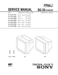
1
Self Diagnosis Supported model SERVICE MANUAL MODEL COMMANDER DEST. CHASSIS NO. KV-2199M70 RM-952 ME BG-3S CHASSIS MODEL COMMANDER DEST. CHASSIS NO. SCC-U30W-A TRINITRON ® COLOR TV KV-2199M70 RM-952 SPECIFICATIONS Note Power requirements 110-240 V AC, 50/60 Hz Power consumption (W) Indicated on the rear of the TV Television system B/G, I, D/K, M Color system PAL, PAL 60, SECAM, NTSC4.43, NTSC3.58 Teletext language English, Arabic, French Channel coverage B/G VHF: E2 to E12 / UHF: E21 to E69 / CATV: S01 to S03, S1 to S41 I UHF: B21 to B68 / CATV: S01 to S03, S1 to S41 D/K VHF: C1 to C12, R1 to R12 / UHF: C13 to C57, R21 to R60 CATV: S01 to S03, S1 to S41, Z1 to Z39 M VHF: A2 to A13 / UHF: A14 to A79 CATV: A-8 to A-2, A to W+4, W+6 to W+84 ˘ (Antenna) 75-ohm external terminal Audio output 5W + 5W Number of terminal Input: 2 Output: 1 Phono jacks; 1 VP-P, 75 ohms ≥ (Audio) Input: 2 Output: 1 Phono jacks; 500 mVrms Output: 1 Minijack Ø D (Video) (Earphone) Picture tube 21 in. Tube size (cm) 54 Measured diagonally Screen size (cm) 51 Measured diagonally Dimension (w/h/d, mm) 640 × 456 × 495 Mass (kg) 27 Design and specifications are subject to change without notice. CAUTION SAFETY-RELATED COMPONENT WARNING!! SHORT CIRCUIT THE ANODE OF THE PICTURE TUBE AND THE ANODE CAP TO THE METAL CHASSIS, CRT SHIELD, OR CARBON PAINTED ON THE CRT, AFTER REMOVING THE ANODE. COMPONENTS IDENTIFIED BY SHADING AND MARK ! ON THE SCHEMATIC DIAGRAMS, EXPLODED VIEWS AND IN THE PARTS LIST ARE CRITICAL TO SAFE OPERATION. REPLACE THESE COMPONENTS WITH SONY PARTS WHOSE PART NUMBERS APPEAR AS SHOWN IN THIS MANUAL OR IN SUPPLEMENTS PUBLISHED BY SONY. –2– KV-2199M70 RM-952 TABLE OF CONTENTS Section Title Page SELF DIAGNOSIS FUNCTION ................................ 4 Section 5-1. Block Diagram ......................................................... 5-2. Frame Schematic Diagram ...................................... 5-3 Circuit Boards Location .......................................... 5-4. Schematic Diagrams and Printed Wiring Boards ... (1) Schematic Diagram of A (1/2) Board ...................... (2) Schematic Diagram of A (2/2) Board ...................... (3) Schematic Diagrams of C3 and VM1 Boards ......... (4) Schematic Diagram of F Board .................................... 5-5. Semiconductors ........................................................ 2. DISASSEMBLY Rear Cover Removal ................................................ Chassis Assy Removal ............................................. F Bracket Removal .................................................. Service Position ....................................................... Replacement of Parts ............................................... 2-5-1. 2-5-2. 2-6. 2-7. 2-8. Replacement of Control Button ....................... Replacement of Light Guide ............................ Terminal Bracket Removal ...................................... Degauss Coil Removal ............................................. Picture Tube Removal .............................................. 20 20 20 20 21 21 21 21 21 22 Beam Landing .......................................................... Convergence ............................................................. Focus Adjustment .................................................... G2 (Screen) and White Balance Adjustments ......... 6-1. 4-5. Adjustments with Commander ................................ Adjustment Method ................................................. Picture Quality Adjustments .................................... A Board Adjustment After IC003 (Memory) Replacement ............................................................. Picture Distortion Adjustment ................................. Chassis ..................................................................... 63 7. ELECTRICAL PARTS LIST ....................................... 65 23 24 26 26 4. CIRCUIT ADJUSTMENT 4-1. 4-2. 4-3. 4-4. 37 40 42 43 45 48 54 59 61 6. EXPLODED VIEW 3. SET-UP ADJUSTMENTS 3-1. 3-2. 3-3. 3-4. Page 5. DIAGRAMS 1. GENERAL ........................................................................ 8 2-1. 2-2. 2-3. 2-4. 2-5. Title 27 28 33 33 34 –3– KV-2199M70 RM-952 SELF DIAGNOSTIC FUNCTION The units in this manual contain a self-diagnostic function. If an error occurs, the STANDBY/TIMER lamp will automatically begin to flash. The number of times the lamp flashes translates to a probable source of the problem. A definition of the STANDBY/TIMER lamp flash indicators is listed in the instruction manual for the user’s knowledge and reference. If an error symptom cannot be reproduced, the remote commander can be used to review the failure occurrence data stored in memory to reveal past problems and how often these problems occur. 1. DIAGNOSTIC TEST INDICATORS When an errors occurs, the STANDBY/TIMER lamp will flash a set number of times to indicate the possible cause of the problem. If there is more than one error, the lamp will identify the first of the problem areas. Result for all of the following diagnostic items are displayed on screen. No error has occured if the screen displays a “0”. Diagnostic Item Description • Power does not turn on No. of times Self-diagnostic STANDBY/TIMER display/Diagnostic lamp flashes result Probable Cause Location Detected Symptoms Does not light — • Power cord is not plugged in. • Fuse is burned out F4601 (F) • Power does not come on. • No power is supplied to the TV. • AC power supply is faulty. • +B overcurrent (OCP) or overvoltage (OVP) • Vertical deflection stopped • Horizontal deflection overdrive 2 times 002:000 or 002:001~255 003:001~255 004:001~255 at the same time • H.OUT Q511 is shorted. (A board) • IC701 is shorted. (C board) • -13V is not supplied. (A board) • IC 503 faulty (A board) • Power does not come on. • Load on power line is shorted. • Has entered standby state after horizontal raster. • Vertical deflection pulse is stopped. • Power line is shorted or power supply is stopped. • White balance failure (no PICTURE) 5 times 005:000 or 005:001~225 • G2 is improperly adjusted. (Note 2) • CRT problem. • Video OUT IC701 is faulty. (C board) • IC301 is faulty. (A board) • No connection A board to C3 board. • No raster is generated. • CRT cathode current detection reference pulse output is small. — 101:00 or 101:001~225 • Discharge CRT (C3 Board) • Static discharge • External noise • Power is shut down shortly, after this return back to normal. • Detect Micro latch up. • Micro reset Note 1: If a + B overcurrent is detected, stoppage of the vertical deflection is detected simultaneously. The symptom that is diagnosed first by the microcontroller is displayed on the screen. Note 2: Refer to screen (G2) Adjustment in section 3-4 of this manual. –4– KV-2199M70 RM-952 2. DISPLAY OF STANDBY/TIMER LIGHT FLASH COUNT 2 times 5 times Lamp ON 0.3 sec. Lamp OFF 0.3 sec. Lamp OFF 3 sec. STANDBY/SLEEP lamp Diagnostic Item +B overcurrent/overvoltage Vertical deflection stopped Flash Count* 2 times White balance failure 5 times * One flash count is not used for self-diagnostic. 3. STOPPING THE STANDBY/TIMER FLASH Turn off the power switch on the TV main unit or unplug the power cord from the outlet to stop the STANDBY/TIMER lamp from flashing. –5– KV-2199M70 RM-952 4. SELF-DIAGNOSTIC SCREEN DISPLAY For errors with symptoms such as “power sometimes shuts off” or “screen sometimes goes out” that cannot be confirmed, it is possible to bring up past occurances of failure for confirmation on the screen: [To Bring Up Screen Test] In standby mode, press buttons on the remote commander sequentially in rapid succession as shown below: [Screen display] / channel [5] / Sound volume [-] / Power ON ˘ Note that this differs from entering the service mode (mode volume [+]). Self-Diagnosis screen display SELF DIAGNOSTIC 002 : 000 003 : 000 004 : 000 005 : 001 Numeral "0" means that no fault has been detected. Numeral "1" means a fault has been detected. 101 : 000 5. HANDLING OF SELF-DIAGNOSTIC SCREEN DISPLAY Since the diagnostic results displayed on the screen are not automatically cleared, always check the self-diagnostic screen during repairs. When you have completed the repairs, clear the result display to “0”. Unless the result display is cleared to “0”, the self-diagnostic function will not be able to detect subsequent faults after completion of the repairs. [Clearing the result display] To clear the result display to “0”, press buttons on the remote commander sequentially as shown below when the diagnostic screen is being displayed. Channel [8] / 0 [Quitting Self-diagnostic screen] To quit the entire self-diagnostic screen, turn off the power switch on the remote commander or the main unit. –6– KV-2199M70 RM-952 6. SELF-DIAGNOSTIC CIRCUIT IC301 Y/CHROMA JUNGLE FROM CRT FROM [+B] Q604 C3 [H] D526 IC001 SYSTEM 21 IK-IN 18 MP/ PROTECT SDA 35 IO-8DAT 45 IC003 MEMORY 5 B-DAT O-LED 51 46 IO-SDAT [V] Q509/507 [+B overcurrent ªOCPº] Occurs when an overcurrent on the +B(135) line is detected by Q604. If Q604 go to ON and the voltage to pin 18 of IC301 should go down when V.SYNC is more than seven verticals in a period, the unit will automatically turn off. [Horizontal deflection overdrive] Occurs when an overdrive on H drive line is detected by D526. Power supply will be shut down when detect it. [Vertical deflection stopped] Occurs when an absence of the vertical deflection pulse is detected by Q509 and IC001 shut down the power supply. [Vertical deflection overcurrent] Occurs when an overcurrent on V drive line is detected by Q507. Power supply will be shut down when detect this by IC001. [White balance failure] If the RGB levels* do not balance or become low level within 5 seconds, this error will be detected by IC301. TV will stay on, but there will be no picture. * (Refers to the RGB levels of the AKB detection Ref pulse that detects IK.) –7– 2 Clean the TV with a dry and soft cloth. Do not use benzine, thinner, or any other chemicals to clean the TV. Do not scratch the picture tube. Do not plug in too many appliances to the same power socket. Do not damage the power cord. Do not install the TV in hot, humid or excessively dusty places. To prevent fire or shock hazard, do not expose the TV to rain or moisture. Do not install the TV in a confined space, such as a bookcase or built-in cabinet. Do not block the ventilation openings of the TV. Pull the power cord out by the plug. Do not pull the power cord itself. Disconnect the TV if you are not going to use it for several days. Do not open the cabinet and the rear cover of the TV. Refer servicing to qualified personnel. Install the TV in a stable position. Do not allow children to climb onto it. 4 Using Your New TV –8– (see page 12). or Using Your New TV To video and audio outputs VIDEO OUT VIDEO IN AUDIO VIDEO To antenna output Audio/Video cable (not supplied) VCR Antenna cable (not supplied) To watch the video, press … Connecting a VCR Antenna cable (not supplied) IEC connector (not supplied) Rear of TV (yellow) (black) 1 To ˘ (antenna) To … 1 (video input) Rear of TV : Signal flow : Signal flow If you wish to connect a VCR, see the “Connecting a VCR” diagram below. Connect the antenna Step 1 Getting Started GENERAL Do not operate the TV if any liquid or solid object falls into it. Have it checked immediately by qualified personnel only. For your own safety, do not touch any part of the TV, the power cord and the antenna cable during lightning storms. • Operate the TV only between 110 – 240 V AC. • Dangerously high voltages are present inside the TV. WARNING The operating instructions mentioned here are partial abstracts from the Operating Instruction Manual. The page numbers of the Operating Instruction Manual remain as in the manual. SECTION 1 KV-2199M70 RM-952 CAUTION –9– 2 1 ONE-PUSH AUTOMATIC PROGRAMMING VHF LOW B/G 1 1 To watch your TV, see page 11. Using Your New TV Note (KV-2199M70 only) • During automatic channel presetting, your TV screen will indicate “B/G”, “I”, “D/K” or “M” for the TV system (“TV SYS”). Tips • If you want to exit automatic channel presetting, press SELECT twice. • If your TV has preset an unwanted channel or cannot preset a particular channel, then preset your TV manually (see page 9). Now You Are Ready. . . ONE-PUSH AUTOMATIC PROGRAMING Front of TV Preset the channels automatically Step 3 Note • Do not use old batteries nor use different types of batteries together. Insert the batteries into the remote Step 2 Do not connect the power cord until you have completed making all other connections; otherwise a minimum leakage current might flow through the antenna and other terminals to ground. Notes • If you connect a stereo VCR, connect the yellow plug to (the yellow jack) and the white plug to (the black jack). • If you connect a VCR to the ˘ (antenna) terminal, preset the signal output from the VCR to the program number 0 on the TV. • When no signal is input to the connected video equipment, the TV screen becomes blue. 5 6 (see page 12). or : Signal flow Video game equipment Note • You can also connect video equipment to the … 1 (video input) jacks at the rear of your TV. 2 Camcorder To video and audio outputs Audio/Video cable (not supplied) To… 2 (video input) To video and audio inputs Audio/Video cable (not supplied) To Ú (monitor output) 1 VCR Using Your New TV (the yellow : Signal flow To antenna output Note • When connecting a stereo VCR, connect the yellow plug to jack) and the white plug to (the black jack). (yellow) (black) Rear of TV Antenna cable (not supplied) Connecting audio/video equipment using the Ú (monitor output) jacks ONE-PUSH AUTOMATIC PROGRAMING Front of TV Connecting a camcorder/video game equipment using the … (video input) jacks To watch the picture of the connected equipment, press … You can connect optional audio/video components, such as a VCR, multi disc player, camcorder, video game or stereo system. Connecting optional components KV-2199M70 RM-952 Using Your New TV or A – 10 – Using Your New TV Note • Use only the supplied screws. Use of other screws may damage the TV. or B 3.8 mm 20 mm Put the cord or chain through the clamps to secure the TV against a wall or B pillar. A With the supplied screws, attach the band to the TV stand and to the rear of the TV using the provided hole. To prevent the TV from falling, secure the TV using one of the following methods: Securing the TV 7 8 0 FAVORITE Press AUTO PROGR. 2 AUTO PROGR b 3 PROGR JUMP 9 6 VHF LOW B/G PIC MODE + or – SELECT PROGR +/– . +/– Number buttons u Using Your New TV (4) Press + or –. (3) Press PROGR +/– or the number buttons until the desired program number appears. (2) Press + or –. The on-screen display will start flashing. (1) Press SELECT until “AUTO PROGRAM” appears. To preset channels automatically from a specified program number Note (KV-2199M70 only) • During automatic channel presetting, your TV screen will indicate “B/G”, “I”, “D/K” or “M” for the TV system (“TV SYS”). Press U to turn on the TV. 1 TV Á ÷ SOUND MODE 8 7 2 5 1 4 Presetting channels automatically ONE-PUSH AUTOMATIC PROGRAMING You can preset up to 100 TV channels in numerical sequence from program number 1 using the remote and the buttons on your TV as well. Presetting channels KV-2199M70 RM-952 Using Your New TV Press PROGR +/– or the number buttons until the desired program number appears. Press + or – until the desired channel picture appears. 2 3 4 – 11 – SELECT PROGR SELECT 9 10 NTSC 3.58 NTSC 4.43 Press SELECT until “MANUAL PROGRAM” appears. 2 3 4 5 Tip • You can also use SELECT and ¸ +/– on the TV to preset channels and skip program numbers. Preset the channel automatically or manually. To preset the skipped program number again Press SELECT. Press PIC MODE. Press + or –. Press PROGR +/– or the number buttons until the unused or unwanted program number appears. 1 Skipping program numbers B/G I D/K M Using Your New TV continued (2) Press + or – to select the appropriate TV system until the picture or sound quality is optimal. TV SYS: B/G Using Your New TV You can use the fine tuning function as below: (1) Select the program number you want to adjust. (2) Press SELECT until “MANUAL PROGRAM” appears on the screen. (3) Press + or – on the remote control once. (4) Press to display “FINE” on the screen. (5) Press + or – continuously until the above problems are minimized. The + or – icon on the screen flashes while tuning. (6) Press SELECT to return to normal screen. (1) Press SELECT until “TV SYS” appears. 1 SECAM Tip • Normally set “COL SYS” to “AUTO”. PAL To use the fine tuning (FINE) function 0 -/-- 9 6 5 8 4 7 AUTO (2) Press + or – to select the appropriate color system until the color is optimal. COL SYS : AUTO (1) Press SELECT until “COL SYS” appears. If the color is abnormal when receiving programs through the ˘ (antenna) terminal or the … (video input) jack To change the color system setting Presetting channels (continued) The fine tuning (FINE) function may help to reduce the following problems: incomplete Teletext display (KV-2199XT only), double images and lines moving across the TV screen. or 3 2 1 VHF LOW B/G MANUAL PROGRAM Using Your New TV If the picture or sound is abnormal when receiving programs through the ˘ (antenna) terminal (KV-2199M70 only) To change the TV system setting Press SELECT. Press + or –. 5 Press SELECT until “MANUAL PROGRAM” appears. 1 Presetting channels manually KV-2199M70 RM-952 – 12 – 3 2 1 Press . +/– to adjust the volume. For double digit numbers, press ÷, then the number (e.g., for 25, press ÷, then 2 and 5). Press PROGR +/– or the number buttons to select the TV program. When the TV is in the standby mode (the u indicator on the TV is lit red), press u on the remote or PROGR +/– on the TV. Press U to turn on the TV. ONE-PUSH AUTOMATIC PROGRAMING This section explains functions used while watching the TV. Most operations can be done using the remote. Watching the TV PROGR 0 Á PROGR FAVORITE SOUND MODE TV JUMP ÷ 9 8 7 PIC MODE p SELECT p 6 5 4 3 2 1 or 8 0 7 -/-- Using Your New TV continued 9 3 6 2 5 1 4 + or – SELECT PROGR +/– JUMP . +/– Number buttons u … ; ¤ 11 12 or The adjusting. PIC ROTATION icon on the screen flashes while Press SELECT repeatedly until “PIC ROTATION” appears, then press + or – to adjust the alignment of the picture position. To cancel, select “OFF”. Press SELECT repeatedly until “INTELLIGENT VOL” appears, then press + or – to select “ON”. Press + or – to select “ “. 2 SELECT LANGUAGE / LANGUAGE / : : ENGLISH Using Your New TV Tip • You can also use SELECT and . +/– on the TV to select the on-screen display language. Press SELECT until “LANGUAGE / : ENGLISH”appears on the screen. 1 Changing the on-screen display language * The picture, sound, and either the program number or video mode are displayed. The on-screen display for the picture and sound information disappears after about 3 seconds. Adjust the picture position when it is not aligned to the TV screen (KV-2199XT only) Adjust the volume of each TV program automatically . Press JUMP. Press Jump back to the previous channel Display the on-screen information* Press … to select “VIDEO 1” or “VIDEO 2”. To return to the TV program, press ;. Watch the video input (VCR, camcorder, etc.) Press U on the TV. Press ¤. Turn off completely Mute the sound Do this Press u. The u indicator on the TV lights up red. Turn off temporarily To Additional tasks Watching the TV (continued) KV-2199M70 RM-952 Using Your New TV After 12 hours No Wake Up timer – 13 – Press SLEEP TIMER:60M After 60 minutes SLEEP TIMER:90M After 90 minutes SLEEP TIMER:30M After 30 minutes SLEEP TIMER:OFF No Sleep Timer Using Your New TV until “SLEEP TIMER: OFF” appears or turn the TV off. To cancel the Sleep timer Press until the desired period of time appears. Setting the Sleep timer Notes • The Wake Up timer starts immediately after the on-screen display disappears. • If no buttons or controls are pressed for more than two hours after the TV is turned on using the Wake Up timer, the TV automatically goes into the standby mode. To continue watching the TV, press any button or control on the TV or the remote. Press until “WAKE UP TIMER: OFF” appears or turn off the TV’s main power. To cancel the Wake Up timer indicator on the TV lights up orange. Press u or set the Sleep timer if you want the TV to turn off automatically. 3 The Select the TV program or video mode you want to display when you wake up. WAKE UP TIMER:12H00M WAKE UP TIMER:OFF After 10 minutes 2 WAKE UP TIMER:10M Press until the desired period of time appears. 1 Setting the Wake Up timer 13 14 FAVORITE SOUND MODE receive mild pictures. listen to sound that emphasizes vocals and background music. receive soft sound. DRAMA SOFT Advanced Operations To ≥ SOFT listen to dynamic and clear sound that emphasizes the low and high sound. ≥ DRAMA SOFT Select ≥ DYNAMIC STANDARD PIC MODE SELECT + or – SOUND MODE DYNAMIC Press SOUND MODE repeatedly until you get the desired sound mode. SOUND MODE receive normal contrast pictures. STANDARD SOFT To select the sound mode To receive high contrast pictures. Select PIC MODE DYNAMIC Press PIC MODE repeatedly until you get the desired picture mode. To select the picture mode PROGR DYNAMIC TV Á Selecting the picture and sound modes You can customize the picture and sound by selecting the picture and sound modes or by adjusting its settings. Customizing the picture and sound Advanced Operations KV-2199M70 RM-952 Using Your New TV TREBLE COLOR BASS BRIGHT PICTURE SHARP HUE* 60 – 14 – 15 Advanced Operations Advanced Operations Notes • When you select a picture or sound mode, the adjusted settings will be reset according to the selected mode. • You can also use SELECT and ¸ +/– on the TV to adjust the sound and picture settings. * “HUE” can be adjusted for NTSC system only. To adjust other items, repeat steps 1 to 2. 3 PICTURE Press + or – to adjust the item. Each time you press SELECT, the setting item will change as follows: SELECT 2 1 Press SELECT until the desired setting appears. Adjusting the picture and sound settings 16 3 6 2 5 1 4 FAVORITE PROGR Á When you use the FAVORITE CH feature for the first time, six preset channels will appear. Press the number button from 1 to 6 to select the desired channel. Press FAVORITE. FAVORITE SOUND MODE 9 JUMP 8 6 3 0 7 ÷ 2 5 1 4 Advanced Operations Press SELECT. 7 -/-- Repeat steps 2 and 3 to set other favorite channels. 9 8 0 4 4 5 or 3 6 2 5 1 Press PROGR +/–, or the number buttons to change the program number. 3 PROGR Press + or – to select the favorite channel you want to change (e.g. 3 PR03). 2 SELECT Press SELECT until “FAVORITE CH SET UP” appears. 1 Changing the favorite channel setting 2 1 Selecting a favorite channel You can display six of your favorite channels for quick and easy selection. You can change the favorite channel setting as well. Viewing your favorite channels FAV O R I T E C H S E T U P 1PR01 2PR02 3PR08 4PR04 5PR05 6PR06 FAV O R I T E C H S E T U P 1PR01 2PR02 3PR03 4PR04 5PR05 6PR06 FAV O R I T E C H S E T U P 1PR01 2PR02 3PR03 4PR04 5PR05 6PR06 1 1PR01 2PR02 3PR03 4PR04 5PR05 6PR06 FAV O R I T E C H FAVORITE + or – PROGR +/– Number buttons KV-2199M70 RM-952 – 15 – 3 1 2 SELECT ÷ FAVORITE SOUND MODE PROGR 0 Á TV 9 JUMP 7 3 6 8 2 5 1 4 CHILD LOCK: ON CHILD LOCK: OFF + or – SELECT Advanced Operations Note • If you preset a locked channel, that particular channel will be unlocked automatically. To unlock the channel, press + or – to select “OFF”. The symbol disappears from the screen. symbol appears on The the screen. Press + or – to select “ON”. Press SELECT until “CHILD LOCK” appears on the screen. Select the TV program you want to lock. You can prevent a child from watching certain programs by using the buttons on the remote control. Blocking the channels (CHILD LOCK) 1 17 18 Viewing Teletext FAVORITE TV Á 8 0 7 ÷ SOUND MODE 2 5 1 4 3 PROGR JUMP 9 6 FASTEXT A/B … ; V to display the A Teletext page (normally the index page) is displayed. If there is no Teletext broadcast, “100” is displayed at the top left corner of the screen. Press text. Advanced Operations Press ;. b 1000/1715 0930/2015 2130/0745 2300/0915 2210/0610 2100/0835 2.7 4 1 2 To ROMA To SYDNEY Dep/Arr 220/0588 2130/1225 2115/1330 2.5 4.6 03:59:09 SQ21A SQ21A SQ24 AZ487 SQ6 CX522 747 747 747 747 747 L10 Flight Alrcraft SQ28 747 PA115 L15 SQ26 747 FR1 MAR To OSAKA 166 From Singapore Day 1.6 To PARIS 2 3 P166 SECTEXT Select a TV channel that carries the Teletext broadcast you want to watch. To turn off Teletext 1 2 Displaying Teletext TV stations broadcast an information service called Teletext via some TV channels. Teletext allows you to receive various information, such as shares market or news. (KV-2199XT only) KV-2199M70 RM-952 – 16 – Press . An overview of the Teletext contents and page numbers appear on the screen. Press the number buttons to enter the three-digit page number of the desired Teletext page.* If you make a mistake, reenter the correct page number. To access the next or previous page, press PROGR +/–. to display the symbol “j” at the top Press … left corner of the screen. To resume normal Teletext operation, press … or . Press . To conceal the information, press the button again. Press A/B . Each time you press A/B , the Teletext display changes as follows: Enlarge upper half n Enlarge lower half n Normal size. 1 Enter the Teletext page number that you want to refer to, then press . 2 When the page number is displayed, press to show the text. check the contents of a Teletext service select a Teletext page hold a Teletext page (stop the page from scrolling) reveal concealed information (e.g., an answer to a quiz) enlarge the Teletext display wait for a Teletext page while watching a TV program Advanced Operations Press the color-coded button on the remote corresponding to the menu you want. The menu page appears on the screen after several seconds. To access a FASTEXT menu This feature allows you to quickly access a Teletext page that uses FASTEXT. When a FASTEXT program is broadcasted, the colored menus appear at the bottom of the screen. The colors of the menus correspond to the red, green, yellow, and blue color-coded buttons on the remote. Using FASTEXT * You can also select a Teletext page of any page number that appears in the colored column at the bottom of the screen using the corresponding colorcoded button on the remote. Do this Press . Each time you press , the screen changes as follows: Teletext n Teletext and TV n TV. To display a Teletext page on the TV picture Additional Teletext tasks 19 20 u indicator ONE-PUSH AUTOMATIC PROGRAMING Inform your nearest Sony service center about the number of times the u indicator flashes. Be sure to note the model name and serial number located on the rear of your TV. Press U (main power) to turn off your TV. Count the number of times the u indicator flashes. Check that the u indicator flashes red a number of times between 3-second intervals. Additional Information 2 3 4 1 Front of TV Your TV is equipped with a self-diagnosis function. If there is a problem with your TV, the u indicator flashes red. The number of times the u indicator flashes indicates the possible causes. Self-diagnosis function Additional Information KV-2199M70 RM-952 – 17 – No sound No picture (KV-2199M70 only) Noisy sound Good picture Noisy sound Distorted picture Noisy sound Snowy picture Symptom Possible cause • The antenna direction is inappropriate. • Signal transmission is low. • Adjust the antenna direction. Contact a Sony dealer for advice. • Try using a booster. • Press U (main power) on the TV to turn off the TV for about five seconds, then turn it on again. • Press u (power). • Check the power cord, antenna and the VCR connections. Additional Information continued • The TV is not turned on. • The power cord, antenna or VCR is not connected. • If the sound of some channels are noisy, • The TV system setting is select the channel, then select the inappropriate. appropriate TV system (“TV SYS”). (page 9) • Turn off or disconnect the booster if it is • Broadcast signals are too in use. strong. • The antenna type is inappropriate. • Check the antenna type (VHF/UHF). Contact a Sony dealer for advice. • Press SELECT until “MANUAL • Channel presetting is PROGRAM” appears on the screen then inappropriate or preset the channel again. (page 9) incomplete. • Check the antenna cable and connection • Connection is loose or the on the TV, VCR and on the wall. (page 4) cable is damaged. Solutions If you find any problem while viewing your TV, please check the following guide. If any problem persists, contact your Sony dealer . Troubleshooting 21 22 • The antenna direction is inappropriate. • Adjust the antenna direction. Contact a Sony dealer for advice. • Keep external speakers or other electrical equipment away from the TV. Do not move the TV while the TV is turned on. Press U (main power) on the TV to turn off the TV for about five minutes, then turn it on again. • Adjust the antenna direction. Contact a Sony dealer for advice. • The magnetic disturbance from external speakers or other equipment, or the direction of the earth’s magnetic field may affect the TV. • The antenna direction is inappropriate. • Press SELECT until “COL SYS ” appears • The color system setting is inappropriate. on the screen, then check the color system setting (usually set this to “AUTO”). (page 10) • Press SELECT until “COLOR” appears • The color level setting is too low. on the screen, then press + or – to adjust the color level. (page 15) Additional Information Abnormal color patches No color • Broadcast signals are reflected by nearby mountains or buildings. • Use a highly directional antenna. • Use the fine tuning (FINE) function. (page 10) Double images or “ghosts” • Turn off or disconnect the booster if it is • Use of a booster is inappropriate. in use. • There is local interference from cars, neon signs, hair dryers, power generators, etc. • The sound is muted. • Press ¤ to cancel the muting. • Do not use a hair dryer or other equipment near the TV. • Adjust the antenna direction for minimum interference. Contact a Sony dealer for advice. Possible cause • The volume level is too low. Solutions • Press ¸ + to increase the volume level. Dotted lines or stripes No sound Good picture Symptom Troubleshooting (continued) KV-2199M70 RM-952 Additional Information – 18 – • The magnetic disturbance from external speakers or other equipment, or the direction of the earth’s magnetic field may affect the TV. • Keep external speakers or other electrical equipment away from the TV. A “boom” sound is heard when the TV is turned on. — –– • Contact your nearest Sony service center. (page 20) The u indicator on your TV flashes red a number of times between 3-second intervals. TV cabinet creaks. • Use the fine tuning (FINE) function. (page 10) Additional Information • The TV’s demagnetizing function is working. This does not indicate a malfunction. • Changes in room temperature sometimes make the TV cabinet expand or contract, making a noise. This does not indicate a malfunction. • Your TV may need service. • There is interference from external sources, e.g., heavy machineries, nearby broadcast station. • Signal transmission is too low. • Try using a booster • Use the fine tuning (FINE) function. (page 10) • Press SELECT until “PIC ROTATION” appears on the screen, then press + or – to align the picture to the TV screen. (page 12) (KV-2199XT only) • The antenna direction is inappropriate. • Adjust the antenna direction. Contact a Sony dealer for advice. Lines moving across the TV screen (KV-2199XT only) Picture slant • The channel carries no Teletext broadcast. Possible cause • Check the antenna cable and connection • Connection is loose or the cable is damaged. on the TV, VCR, and at the wall. (page 4) — “100” appears on the top of the screen and there is no Teletex display. (KV-2199XT only) Teletext display is incomplete (snowy picture or double images). (KV-2199XT only) Solutions 23 24 U (main power) button (11) ONE-PUSH AUTOMATIC PROGRAMING ¸ +/– (volume) buttons (11) … (TV/video) button (12) 7 (earphone) jack 6 SELECT button (10) 5 AUTO PROGR (program) button (5) 4 3 2 PROGR +/– (program) buttons (11) 1 ONE-PUSH AUTOMATIC PROGRAMMING Additional Information 2 Front panel Refer to the pages indicated in parentheses ( ) for details. Identifying parts and controls Ø Symptom KV-2199M70 RM-952 – 19 – PROGR 0 Á FAVORITE TV 9 JUMP 8 7 ÷ SOUND MODE 6 5 4 3 2 1 1 u (power) button (11) 2 ; (TV) button (12) 3 Number buttons (11) 4 JUMP button (12) 5 PROGR +/– buttons (11) 6 SELECT button (9) 7 PIC MODE button (14) 8 +/– buttons (8) 9 (display) button (12) !º ¤ (muting) button (12) !¡ … (video) button (12) !™ . +/– (volume) buttons (11) !£ A/B button (not used for KV-2199M70) !¢ Timer setting buttons (13) (wake up timer) (sleep timer) !∞ FAVORITE button (16) !∞ !¢ !™ !£ !¡ 0 9 Remote Control 1 8 7 6 5 4 3 2 Á FAVORITE TV PROGR 0 SOUND MODE JUMP 8 7 ÷ 3 5 4 9 6 2 1 !§ For Teletext operations Green Additional Information Button function For general TV operations Label color White Names/symbols of buttons on the remote are indicated in different colors to represent the available functions. !§ SOUND MODE button (14) !¶ Teletext operation buttons (Not used for KV-2199M70) (text) (enlarge) (reveal) (hold) (index) (text clear) p (FASTEXT: red, green, yellow, blue) !¶ 25 KV-2199M70 RM-952 – 20 – 1 Chassis assy Lever 2-2. CHASSIS ASSY REMOVAL Lever 2 Rear cover 1 One screw (+BVTP 4 × 16) 1 Four screws (+BVTP 4 × 16) 2-1. REAR COVER REMOVAL 2-4. SERVICE POSITION (Note: Remove F Bracket first.) 3 One screw (+BVTP 3 × 12) 2-3. F BRACKET REMOVAL DISASSEMBLY SECTION 2 2 F board Lever 1 Three connectors KV-2199M70 RM-952 2-5. REPLACEMENT OF PARTS Multi button – 21 – Light guide Cut Light guide 2-5-2. REPLACEMENT OF LIGHT GUIDE Cut One screw (+BVTP 3 × 12) Multi button 2-5-1. REPLACEMENT OF MULTI BUTTON Two screws (+BVTP 3 × 12) For replacement of the Multi Button and Light Guide, cut the welded portions from them, exchange with the new parts, and fix them with screws (+BVTP) respectively. Picture tube 2 Tension spring 1 Demagnetization coil 2-7. DEGAUSS COIL REMOVAL A board Terminal board bracket 2-6. TERMINAL BRACKET REMOVAL KV-2199M70 RM-952 1 Anode cap 6 Four screws (Tapping screws) 5 Deflection yoke 7 Neck assy 4 C3 board 3 F board 2-8. PICTURE TUBE REMOVAL Cushion 2 A board a b – 22 – HOW TO HANDLE AN ANODE-CAP 1 Do not damage the surface of anode-caps with sharp shaped objects. 2 Do not press the rubber too hard so as not to damage the inside of anode-cap. A metal fitting called the shatter-hook terminal is built into the rubber. 3 Do not turn the foot of rubber over too hard. The shatter-hook terminal will stick out or damage the rubber. • 3 When one side of the rubber cap is separated from the anode button, the anode-cap can be removed by turning up the rubber cap and pulling it up in the direction of the arrow c. Anode button c 2 Using a thumb pull up the rubber cap firmly in the direction indicated by the arrow b. b 1 Turn up one side of the rubber cap in the direction indicated by the arrow a. a • REMOVING PROCEDURES NOTE : After removing the anode, short circuit the anode of the picture tube and the anode cap to the metal chassis, CRT shield or carbon paint on the CRT. • REMOVAL OF ANODE-CAP KV-2199M70 RM-952 KV-2199M70 SECTION 3 RM-952 SET-UP ADJUSTMENTS • The following adjustments should be made when a complete realignment is required or a new picture tube is installed. • These adjustments should be performed with rated power supply voltage unless otherwise noted. Perform the adjustments in the following order : 1. Beam Landing Controls and switches should be set as follows unless otherwise noted: PICTURE control ........................................................... normal BRIGHTNESS control ................................................... normal 2. Convergence 3. Focus 4. White Balance Note : Test Equipment Required. 1. Color-bar/Pattern Generator 2. Degausser 3. Oscilloscope ................................................................................................................................................................................................................................ Preparation : • In order to reduce the influence of geomagnetism on the set's • Neck assy DY picture tube, face it east or west. Switch on the set's power and degauss with the degausser. 3-1. BEAM LANDING Note: Neck Assy is exactly behind DY (no gap between Neck Assy and DY) 1. Input a white signal with the pattern generator. Contrast normal Brightness 2. Position neck assy as shown in Fig3-2. } Fig. 3-2 3. Set the pattern generator raster signal to a green raster. 4. Move the deflection yoke to the rear and adjust with the purity Blue control so that the green is at the center and the blue and the red take up equally sized areas on each side. Red Green (See Figures 3-1 through 3-3.) 5. Move the deflection yoke forward and adjust so that the entire screen is green. (See Figure 3-1.) 6. Switch the raster signal to blue, then to red and verify the condition. 7. When the position of the deflection yoke has been decided, Fig. 3-3 Purity control corrects this area. fasten the deflection yoke with the screws and DY spacers. 8. If the beam does not land correctly in all the corners, use a magnet to adjust it. (See Figure 3-4.) b a c d Disk magnets or rotatable disk magnets correct these areas (a-d). Deflection yoke positioning corrects these areas. b c a Fig. 3-1 d Fig. 3-4 – 23 – KV-2199M70 RM-952 3-2. CONVERGENCE Preparation : • Before starting this adjustment, adjust the focus, horizontal size and vertical size. • • Minimize the brightness setting. Provide dot pattern. 1 V. STAT a a b (1) b b Horizontal and Vertical Static Convergence Center dot B B G G R R 2 H. STAT VR R a G b B R G B R H. STAT VR G R G B B V.STAT Magnet 3 a b b a B R G G b RV 702 R B 4 BMC (Hexapole) Magnet. If the red, green and blue dots are not balanced or aligned, then use the BMC magnet to adjust in the manner described below. C3 board R G B R B R G B R G B R G B (Moving vertically), adjust the V.STAT magnet so that the red, green and blue dots are on top of each other at the center of the screen. Purity BMC G G R BMC (Hexapole) Purity V.STAT V.STAT – 24 – B KV-2199M70 RM-952 4 Y separation axis correction magnet adjustment. Red Blue 1. Receive the cross-hatch signal and adjust [PICTURE] to [MIN] and [BRIGHTNESS] to [STANDARD] . Neck assy Neck assy 2. Adjust the Y separation axis correction magnet on the neck assembly so that the horizontal lines at the top and bottom of the screen are straight. Red VM1 board Blue VM1 board Note 1. The Red and Blue magnets should be equally far from the horizontal center line. 2. Do not separate the Red and Blue magnets too far. (Less than 8 mm) (2) Dynamic Convergence Adjustment Preparation: • Before starting this adjustment, adjust the horizontal static convergence and the vertical static convergence RB B R YCH TLV on DY YCH TLV – 25 – KV-2199M70 RM-952 (3) Screen-corner Convergence 3-4. G2 (SCREEN) AND WHITE BALANCE ADJUSTMENTS b 1. G2 (SCREEN) ADJUSTMENT 1) Set the PICTURE to normal. a 2) Put to VIDEO input mode without signals. 3) Connect R, G and B of the C3 board cathode to the oscilloscope. a-d : screen-corner misconvergence c 4) Adjust BRIGHTNESS to obtain the cathode voltage to the value below. d 5) Adjust G2 (Screen) on FBT until picture shows the point before cut-off. Fix a Permalloy assy corresponding to the misconverged areas. Fix a Permalloy assy corresponding to the misconverged areas b 175 V ± 2 (VDC) 0V a 2. WHITE BALANCE ADJUSTMENT 1) Set to Service Mode (Refer Section 4-1: ADJUSTMENTS WITH COMMANDER). 2) Input white raster signal. 3) Set the PICTURE to minimum. 4) Select GCT (WHB 4) and BCT (WHB 5) with [1] and [4], and adjust the level with [3] and [6] for the best white balance. 5) Set the PICTURE to maximum. 6) Select GDR (WHB 1) and BDR (WHB 2) with [1] and [4], and adjust the level with [3] and [6] for the best white balance. 7) Write into the memory by pressing [MUTING] then [0]. c d 3. SUB BRIGHT ADJUSTMENT 1) Set to service mode. a to d : Permalloy assembly 2) Input a staircase signal of black to white from the pattern generator. 3-3. FOCUS ADJUSTMENT Adjust FOCUS control on the flyback transformer for the best focus. 3) BRIGHTNESS .... 50%. PICTURE ............ MINIMUM 4) Select SBR (WHB7) with [1] and [4], and adjust SBR (WHB7) level with [3] and [6] so that the second stripe from the right is dimly lit. White second from the right Black FOCUS SCREEN FLYB ACK TRANSFORMER (T503) – 26 – KV-2199M70 SECTION 4 RM-952 CIRCUIT ADJUSTMENTS 4-1. ADJUSTMENTS WITH COMMANDER Service adjustments are made with the RM-952 that comes with this unit. a. ENTERING SERVICE MODE With the unit on standby ↓ [DISPLAY] 1, 4 ↓ 3, 6 ↓ Select the adjustment item. [MUTING] Writes. ↓ - ↓ 5 ↓ VOL (+) ↓ [POWER] This operation sequence puts the unit into service mode. Raise/lower the data value. Executes the writing. 7, 8, - All the data becomes the values in memory. All user control goes to the standard state. 5, - Service data initialization (Be sure not to use usually.) 2, - Write 50Hz adjustment data to 60Hz, or vice versa. b. METHOD OF CANCELLATION FROM SERVICE MODE Set the standby condition (Press [POWER] button on the commander), then press [POWER] button again, hereupon it becomes TV mode. c. METHOD OF WRITE INTO MEMORY 1) Set to Service Mode. 2) Press [1] (UP) and [4] (DOWN), select an item of adjustment. 3) Press [MUTING] button and it will indicate WRITE on the screen. 4) Press [0] button to write into memory. d. MEMORY WRITE CONFIRMATION METHOD 1) After adjustment, pull out the plug from AC outlet, and then 1 2 3 4 5 6 7 8 9 ÷ SOUND MODE plug into AC outlet again. 2) Turn the power switch ON and set to Service Mode. 0 JUMP Á PROGR 3) Call the adjusted items again to confirm adjustments were made. The screen display is : FAVORITE Device Name Marking of virgin NVM Item Name Item No Mode Data TV GEO 00 HPS 1C p SERVICE 626S 1.0C 59 7F 0 000A 50 PAL, SECAM : 50 NTSC : 60 RM-952 Suffix No (OEM Code) Software version Total Power-On time (hours) – 27 – KV-2199M70 RM-952 4-2. ADJUSTMENT METHOD Item Number 00 of device GEO This explanation uses H-Position as an example. 1. Select “GEO 00 HPS” with the 1 and 4 buttons. Use the same method for all Items. Use 1 and 4 to select the adjustment item, use 3 and 6 to adjust, write with [MUTING], 2. Raise/lower the data with the 3 and 6 buttons. 3. Select the optimum state. (The standard is 1F for PAL reception.) then execute the write with -. 4. Write with the [MUTING] button. (The display changes to WRITE.) Note : 1. In [WRITE], the data for all items are written into memory together. 5. Execute the writing with the - button. (The WRITE display will be changed to red color while excuting, and back 2. For adjustment items that have different standard data between 50Hz or 60Hz, be sure to use the respective to SERVICE.) GEO 00 626S 1.0C GEO 00 626S 1.0C input signal after adjustment. HPS 1F 59 7F SERVICE 50 0 HPS 1F WRITE 50 59 7F 0 000A 000A GREEN Adjusted with [3] and [6] buttons. GREEN Written with [MUTING] GEO 00 626S 1.0C HPS 1F 59 7F SERVICE 50 0 000A RED The WRITE display then the display returns to a green SERVICE. Write executed with [0] – 28 – 0 1 2 3 4 5 6 7 8 9 0A 0B 0C 0D 0E 0 1 2 3 4 5 6 7 0 1 2 3 0 1 2 3 4 5 6 7 8 9 0A 0B 0C GEO WHB SAJ – 29 – VP EHT GMA YDL SST SSP SLV SBF DYC ABL VTH SFO DCX SHT PMX SHU SSH SCL RDR GDR BDR RCT GCT BCT BMN SBR HPS HSZ PAP TLT VPS VSZ SCO VLN BOW AGL UPN LPN HBL LBL RBL Functionality No Name Device Name Adjustment Item Table 07 2 08/07/08 1 1 2 22 1 1 1 1 1 1 37 8 3 1F 25/2A 2A 2A 7 7 7 15 28 1E/16 1F 1F 7 1F 1F 7 7 7 7 1F 2F 1 0F 0F Note 0F 03 0F 03 03 03 3F 1 1 1 1 1 1 3F 0F 0F 3F 3F 3F 3F 0F 0F 0F 1F 3F 3F 3F 3F 0F 3F 3F 0F 0F 0F 0F 3F 3F 1 0F 0F Data Range TV/Video TV/Video NTSC/others DYNAMIC/others DYNAMIC/others DYNAMIC/others SECAM/others SECAM/others SECAM/others 50/60HZ 50/60HZ 50/60HZ 50/60HZ 50/60HZ 50/60HZ 50/60HZ 50/60HZ 50/60HZ 50/60HZ 50/60HZ 50/60HZ 50/60HZ 50/60HZ Note for Different Data EHT Comp 50/60HZ Gamma Correction NTSC/others Y Delay PAL/SECAM/NTSC SECAM ID Start Position SECAM ID Stop Position SECAM ID Level SECAM BELL fO Dynamic Color on/off ABL Mode Switching (except STANDARD) ABL Detection Vth Switching FO Switching for Sharpness NTSC/others DC Trans. Ratio Switching Pre-/Overshoot ratio Switch NTSC/others Picture Maximum Data Sub Hue Control Sub Sharpness Control Sub Color Control R Drive G Drive B Drive R Cutoff G Cutoff B Cutoff Brightness Minimum Data Sub Brightness Control H Position H Size Pin Amp Trapezium V Position V Size S Correction V Linearity AFC Bow AFC-Angle Upper Pin Lower Pin H Blanking on/off Left H Blanking Right H Blanking Function 15 (3-0) 0B (1-0) 0C (3-0) 1B (1-0) 1B (3-2) 1C (1-0) 1C (7-2) 0A (1) 09 (1) 09 (0) 05 (1) 06 (1) 06 (0) 09 (7-2) 0A (7-2) 0B (7-2) 07 (3-0) 08 (7-4) 08 (3-0) 12 (7-2) 11 (7-2) 13 (7-2) 15 (7-4) 0F (7-2) 0E (7-2) 10 (7-4) 10 (3-0) 16 (7-4) 16 (3-0) 14 (7-2) 18 (7-2) 18 (1) 17 (7-4) 17 (3-0) Register No. (bit) CXA2130S(88H) CXA2130S(88H) CXA2130S(88H) CXA2130S(88H) Slava Address 85 (3-0) 1A1 (1-0) 8C (3-0) 6A (1-0) 6A (3-2) 6B (1-0) 6B (7-2) 59 (1) 58 (1) 58 (0) 196 (1) 55 (1) 197 (0) 95 99 9A 9B 8F (7-2) 90 (7-2) 91 (7-2) 93 (3-0) 94 (7-4) 94 (3-0) 95 98 82 (7-2) 81 (7-2) 83 (7-2) 86 (7-4) 7F (7-2) 7E (7-2) 80 (7-4) 80 (3-0) 86 (7-4) 86 (3-0) 84 (7-2) 88 (7-2) 67 (1) 87 (7-4) 87 (3-0) RAM Address (bit) KV-2199M70 RM-952 0D 0E 0F 10 11 12 13 14 15 16 17 18 19 1A 0 1 2 3 4 5 6 7 8 0 1 2 3 4 5 6 7 8 9 0A 0B 0C 0D 0E 0F 10 11 12 VP AP MSP – 30 – WST WBT WLL WAC WDL NDL SDL AGC REL CRM ACO FP FPM FH FHM WGP NIP ERR VOL INF INS PH1 PH2 PH3 PH4 BCS TCS TRF HDW AFC HOS HSS VSS HMS YUV CDV RON GON BON PON BLK VMC Functionality No Name Device Name Adjustment Item Table 15 EA 5 0 30 20 10 1 28 0 1 1B 32 36 65 2A 6D 50 6D 5 0A 3 0 0 0 2 2 2 0 01/00/01 7 0 0 1 1 1 1 1 1 1 0 0 Note FF FF FF 0F FF FF FF 1 3F 1 1 7F 7F 7F 7F 7F 7F FF FF 3F 3F 3 3 3 3 3 3 3 1 03 0F 1 1 1 1 3 1 1 1 1 1 1 Data Range W/G Stereo Threshold W/G Bilingual Threshold W/G Monaural Threshold W/G Agreement Count W/G Search Delay NICAM Search Delay Stereo status Read Delay AGC Switch Auto/Constant AGC Gain at Constant Mode Carrier muting on/off Audio Clock out on/off FM Prescale for non-M system FM Prescale for M system FM Prescale for HDEV FM Prescale for HDEV and M W/G Prescale NICAM Prescale Auto FM switch Threshold Loud Speaker gain 7000h to 7ffoh Input Attenuation When surround on Input Attenuation When surround off Phase 1 Register Selection Phase 2 Register Selection Phase 3 Register Selection Phase 4 Register Selection Bass Center Shift Treble Center Shift RF Treble Offset H Drive Pulse Width Switch AFC Gain Control H Oscillation Slice Level of H Sync Sep. Slice Level of V Sync Sep. Macro Vision C/m off/on YUV Switch Control CD mode for Video R ON G ON B ON P ON BLK Off VM Off Function Video only not memorized not memorized not memorized not memorized 50/60Hz TV/Video Note for Different Data BB (7) BB (6-1) BB (9) 83 (5) 0E (7-0) 0E (7-0) 0E (7-0) 0E (7-0) 0E (7-0) 10 (7-0) 21 (10-3) 0000 (15-4) #4 (3-0) #5 (3-0) #5 (3-0) 02 00 (5-0) 00 (6) 0F (1-0) 0C (7-4) 0D (1) 0D (0) 0E (0) 01 (0) 0D (5-4) 01 (3) 01 (2) 01 (1) 00 (7) 12 (0) 13 (0) Register No. (bit) MSP3415D(84H) TDA7429 Slava Address 157 (7-0) 158 (7-0) 159 (7-0) 15A (3-0) 15B (7-0) 15C (7-0) 15D (7-0) 108 (7) 108 (6-1) 107 (9) 10C (5) 16C (6-0) 16D (6-0) 16E (6-0) 16F (6-0) 170 (6-0) 138 (6-0) 166 (7-0) 1A7 (7-0) 19D (5-0) 19E (5-0) 76 (1-0) 76 (3-2) 76 (5-4) 76 (7-6) 1A8 (1-0) 1A9 (1-0) 1A9 (5-4) 4F (6) 8D (1-0) 5B (7-4) 5C (1) 6C (0) 7E (0) 50 (0) 19F (5-4) 50 (3) 50 (2) 50 (1) 4F (7) 61 (0) 62 (0) RAM Address (bit) KV-2199M70 RM-952 0 1 2 3 4 5 6 7 0 1 2 OPM OPB OP1 OP2 OP3 OSH COM APC TSY MUT AFM RFB DBL TXH TXV FF E3 0 0A 0 1 0 0 1 0 0 1 0 Note FF FF FF 3F 03 1 03 1 1 3 1 3 7 Data Range Optional Bits 1 (see below) Optional Bits 2 (see below) Optional Bits 3 (see below) OSD H Position Comb Selection APC Switch TV Sys at Auto TV Sys No Signal Mute Auto FM switch C-BPF Control Disable Blueback Function Teletext Horizontal Position Teletext Vertical Position Function Option-Bits Option-Misc Note for Different Data Register No. (bit) (58H) Slava Address 45 46 47 AC (7-2) A5 (7-6) A4 (5) A4 (4-3) A4 (0) A4 (1) A4 (5-4) A4 (2) 18D (6-4) 18D (1-0) RAM Address (bit) NOTE • shaded items are fixed data. • Standard data listed on the Adjustment Item Table are reference values, therefore it may be different for each model and for each mode. • Note for Different Data Those are the standard data values written on the microprocessor. Therefore, the data values of the modes and stored respectively in the memory. In case of a device replacement, adjustment by rewriting the data value is necessary for some items. 0 1 Functionality No Name TXT Device Name Adjustment Item Table KV-2199M70 RM-952 – 31 – KV-2199M70 RM-952 ITEM INFORMATION. No. OPB0 OP1 Item KV-2199M70 XTAL 4.43 XTAL 3.58 SECAM 2nd. Lang B/G I D/K M 1 1 1 1 1 1 1 1 TOP NICAM HDEV Thai Bil – DVD Input 0 0 0 0 0 0 1 0 Pic Rot 2199 Curve Auto PIC Auto TV sys US ST Arabic 11 KEY Chinese 0 1 1 0 0 1 0 0 No. OPB1 OP2 Item KV-2199M70 AV Input No. OPB2 OP3 Item KV-2199M70 – 32 – KV-2199M70 RM-952 4-3. PICTURE QUALITY ADJUSTMENTS BELL FILTER ADJUSTMENT SUB COLOR ADJUSTMENT 1. Input SECAM color-bar signal. 1. Input a PAL color-bar. 2. Set to the following condition: 2. Connect the dual-trace oscilloscope to the pin 9 (R-Y) of CN303 (not mounted). PICTURE 100%, BRIGHTNESS 50%, COLOR 50% 3. Connect an oscilloscope to pin 1 (B OUT) of CN305, A board. 3. Adjust SERVICE MODE, ITEMS ‘SBF’ as shown below. 4. Set to Service Mode and select SAJ 3 ‘SCL’ with 1 and 4 of the commander then adjust to VB2=VB3=VB4 with 3 and 6. 5. Press [MUTING] → - of the commander to write the data. 6. Adjust SAJ 3 ‘SCL’ as step 2 to 5 when receiving NTSC colorbar. 4-4. A BOARD ADJUSTMENT AFTER IC003 (MEMORY) REPLACEMENT When replacing IC003 (MEMORY), be sure to change IC001 (µCOM) to the following new IC at the same time. IC001(µ-CON): CXP86449-626S VB1 VB2 VB3 VB4 VB2 = VB3 = VB4 1. Enter to Service Mode. 2. Press commander buttons 5 and - (Data Initialize), and 2 SUB HUE ADJUSTMENT and - (Data Copy) to initialize the data. 1. Select Video 1. 2. Input a NTSC color-bar, video into Video 1. 3. Call each item number and check if the respective screen shows the normal picture. 3. Set the following condition: PICTURE 100%, BRIGHTNESS 50%, COLOR 50% In cases where items are not well adjusted, rectify the items with fine adjustment. 4. Connect an oscilloscope to pin 1 (B OUT) of CN305, A board. 5. Select SAJ 1 ‘SHU’ with 1 and 4 of the commander by setting to Service Mode and adjust to VB1=VB2=VB3=VB4 with 3 and 6. Write the data per each item number ([MUTING] +-). 4. Select item numbers “OPB0” (OP1), “OPB1” (OP2) and “OPB2” (OP3) and respectively set the bit per model with command buttons 3 and 6. 5. Press commander buttons 8 and - (Test Normal) to return to the data that was set on the shipment from the factory. VB1 VB2 (This will also cancel Service Mode.) VB3 VB4 VB1 = VB2 = VB3 = VB4 6. Press [MUTING] → - of the commander to write the data. – 33 – KV-2199M70 RM-952 4-5. PICTURE DISTORTION ADJUSTMENT Item Number 00 – 0B GEO 0 HPS (H POSITION) GEO 1 HSZ (H SIZE) GEO 2 PAP (PIN AMP) GEO 3 TLT (TRAPEZIUM) GEO 4 VPS (V POSITION) GEO 5 VSZ (V SIZE) GEO 6 SCO (VERTICAL S-Correction) GEO 7 VLN (V LINEARITY) GEO 8 BOW (AFC.BOW) GEO 9 AGL (AFC.ANGLE) GEO 0A UCP (UPPER CORNER PIN) GEO 0B LCP (LOWER CORNER PIN) – 34 – 3P MONITOR OUT VIDEO IN 2 (FRONT) J902 VIDEO IN 1 JACK BLOCK J401 4P <slave: C0H> TU101 BTF-LG433(I) <slave: 84H> L out 2 V out 2 V2 L in V2 V in V1 L in V1 V in TV L in TV V in – 37 – <slave: 80H> IC203 TDA7429S AUDIO PROSESSOR V1 out V2 V in V1 V in TV V in Mon out 4 12 43 6 COMB Y in CN304 9 COMB C in 32 31 30 <slave:88H> YC JUNGLE IC301 CXA2130S 7 COMB FILTER (Glass Combs) V out MAIN. TUVIF with STEREO DECODER (MSP3415) Y out 5-1. BLOCK DIAGRAM Additional Color Matrix RM-952 U out DIAGRAM KV-2199M70 – 38 – IC001 CXP86441 Ucom SYSTEM 14 13 11 18 19 I2L SIRCS VD- VD+ E/W H-DRIVE Q506 2SC2688 MEMORY IC003 ST24C08FB6 RECEIVER SBX1981-11 IC901 PIN-CONT IC502 NJM2903D H. PULSE H. DRIVE C3 B out G out R out 9V REC IC603 5V REC IC604 +5V 7V 11V – 39 – VM DRIVE Q5902/5906 POWER IC IC601 STR-F6656 LINE FILTER T601 F LINE FILTER T4601 AC CORD FBT T503 NX-1748 RM-952 KV-2199M70 CRT A51LPT70X THP THP600 DGC DY Y21RSA-S NECK ASSY STB SW TR Q605 2SK2845 VM1 SP ASSY SRT T603 STB TRANS T604 +9V *-audio 3D Vcc *+audio 3D Vcc Audio Front Vcc +B 5V REG & RESET IC002 MM1319AF V-OUT IC503 TDA8172 PMC L509 HLC L510 CRT SOCKET H-OUT Q511 2SC4927 STV5112 Q704-712 PIN-OUT Q505 IRF614 HDT T501 BLUE OUT 24 B out IK in GREEN OUT 23 G out 21 RED OUT AUDIO OUT IC201 TA8223K 22 R out BLK 28 29 30 31 R G B 15 37 39 40 V in RM-952 Y in KV-2199M70 U in SECTION 5 VM out F (CISPR) PICTURE TUBE AC IN AC IN CRT E CN704 5-2. FRAME SCHEMATIC DIAGRAM CN4601 1 2 1 RM-952 1 2 CN4603 GND KV-2199M70 CN4602 AC OUT AC OUT 1 CN104 1 1 2 3 C3 (RGB OUT) GND CN1802 N/S COIL NC N/S COIL + NS COIL CN702 – 40 – 1 G2 FBT CN305 1 2 3 4 5 6 CN703 CN701 B G R GND IK 9V 200V E H1 B G R GND IK 9V 1 2 3 1 2 3 4 5 6 CN601 AC IN AC IN 2 1 CN505 1 2 3 200V GND H1 CN604 1 2 3 DGC NC DGC DGC A (POWER SUPPLY, HV, MICON, Y/C JUNGLE) DY ASSY 1 2 3 4 5 6 CN901 PH L OUT SP L OUT SP GND SP GND SP R OUT PH R OUT DY1 1 2 3 4 5 6 H+ H+ HHVV+ CN5901 VM GND 9V VM MUTE GND NC +B 1 2 3 4 CN605 3D - VCC GND GND 3D + VCC 1 2 3 4 5 6 7 NECK ASSY VM1 VELOCITY MODULATION CN201 5 6 7 L OUT GND R OUT 1 2 3 4 9V MUTE PROT GND 1 2 3 4 5 6 7 CN306 VM GND 9V VM MUTE GND NC +B – 41 – RM-952 RM-952 A 5-3. CIRCUIT BOARDS LOCATION KV-2199M70 KV-2199M70 – 42 – F VM1 C3 KV-2199M70 RM-952 5-4. SCHEMATIC DIAGRAMS AND PRINTED WIRING BOARDS Note: • All capacitors are in µF unless otherwise noted. • All electrolytic capacitors are rated at 50V unless otherwise noted. • All resistors are in ohms. kΩ = 1000Ω, MΩ = 1000kΩ • Indication of resistance which does not have rating electrical power is as follows. Pitch: 5 mm Rating electrical power 1/4W (CHIP: 1/10W) • • • • : nonflammable resistor. : internal component. : panel designation or adjustment for repair. All variable and adjustable resistors have characteristic curve B unless otherwise noted. ¢ • Readings are taken with a color-bar signal input. no mark : PAL ( ) : SECAM [ ] : NTSC 3.58 « » : NTSC 4.43 • Readings are taken with a 10 MΩ digital multimeter. • Voltage are dc with respect to ground unless otherwise noted. • Voltage variations may be noted due to normal production tolerances. • All voltages are in V. • :Cannot be measured. * • Circled numbers are waveform references. • :B + bus. • :B – bus. • :signal path. Reference information RESISTOR : RN : RC : FPRD : FUSE : RS : RB : RW :* COIL : LF-8L CAPACITOR : TA : PS : PP : PT : MPS : MPP : ALB : ALT : ALR METAL FILM SOLID NONFLAMMABLE CARBON NONFLAMMABLE FUSIBLE NONFLAMMABLE METAL OXIDE NONFLAMMABLE CEMENT NONFLAMMABLE WIREWOUND ADJUSTMENT RESISTOR MICRO INDUCTOR TANTALUM STYROL POLYPROPYLENE MYLAR METALIZED POLYESTER METALIZED POLYPROPYLENE BIPOLAR HIGH TEMPERATURE HIGH RIPPLE Note: The component identified by shading and mark ! are critical for safety. Replace only with part number specified. – 43 – KV-2199M70 RM-952 A BOARD WAVEFORMS 1 2 3 4 PAL 4 SECAM 4.5Vp-p (V) 3.8Vp-p (V) 3.7Vp-p (V) 1.1Vp-p (H) 1.3Vp-p (H) 4 NTSC 3.58 4 NTSC 4.43 5 PAL/NTSC 3.58 5 SECAM/NTSC 4.43 6 1.2Vp-p (H) 0.8Vp-p (H) PAL : 0.9Vp-p (V) NTSC 3.58 : 0.6Vp-p (V) 1.0Vp-p (V) 0.8Vp-p (H) 7 PAL 7 SECAM 7 NTSC 3.58 7 NTSC 4.43 8 PAL 1.1Vp-p (H) 1.0Vp-p (H) 0.7Vp-p (H) 8 SECAM 8 NTSC 9 1.1Vp-p (H) 0.8Vp-p (H) 0.8Vp-p (H) 11 3.1Vp-p (H) 13 NTSC 4.43 0.9Vp-p (H) 12 PAL/NTSC 3.58 3.0Vp-p (H) 14 125Vp-p 12 SECAM 3.0Vp-p (H) 15 920Vp-p 1.2Vp-p (H) 10 PAL/NTSC PAL : 2.7Vp-p (H) NTSC : 2.8Vp-p (H) 12 NTSC 4.43 3.1Vp-p (H) 16 1.4Vp-p (V) – 44 – 1.1Vp-p (H) 10 SECAM 0.8Vp-p (H) 13 PAL/SECAM/NTSC 3.58 1.0Vp-p (H) J I H G F E D C B V 5 LED1 9 KEY1 CN3905 R915 3.3k :CHIP 4.8 1 0.47 C019 47 25V 5 6 7 3 2 4 2 1 R048 10k :CHIP C032 16V B:CHIP 3 R910 :CHIP :CHIP 5V D903 # 7V L004 JW(5mm) 4.9 R056 10k :CHIP # L CV/Y 0 C026 0.1 25V Q902 UN2213 0 LED DRIVE C913 100 10V L905 L001 JW(5mm) R 0 C034 0.01 F:CHIP 10k C006 0.1 25V B:CHIP 5V R049 # JW201 15.0MM R207 1.5k :CHIP 7 6 C008 100p CH:CHIP CN001 # 0 2 0 1 3 0 R021 10k :CHIP 4 0 C204 0.033 :CHIP 52 2 :CHIP C048 100p CH:CHIP 1 51 R002 100 :CHIP R019 10k :CHIP 50 R003 0 :CHIP 48 14 5 R066 1k :CHIP C041 CH:CHIP 4 C217 10 NF2/R IN 13 0 C005 220p B:CHIP 46 47 IC001 CXP86449-626S CONTROLLER 100p 3 49 C004 220p B:CHIP 15 0.6 R210 56 JW202 5.0MM C206 0.0022 :CHIP JW204 # 0 JW203 # C207 0.033 :PP R209 3.3k :CHIP C264 2.2 F:CHIP 16V :CHIP C003 100p CH:CHIP R005 100 :CHIP 100 R007 0 :CHIP C205 0.0022 :CHIP R008 4.7k :CHIP R208 3.3k :CHIP C202 8200p :CHIP C265 2.2 16V F:CHIP R004 10k C025 # R050 C029 # R047 :CHIP R067 1k C002 # 5 C203 8200p :CHIP R205 3.3k :CHIP JW075 # C226 1 10V :CHIP R202 15k :CHIP R203 R204 3.3k 3.9k :CHIP :CHIP C225 # R206 3.9k :CHIP IC003 M24C08-BN6 NVM 8 1.1 1.1 – 45 – R055 :CHIP 0 0 C007 47 16V FB103 # JW017 # JW006 # B:CHIP Q003 Q004 UN2111 4.9 UN2211 SWITCH 0 SWITCH C030 22 C028 0.022 B:CHIP 4.9 4.9 Q901 UN2213 LED DRIVE 0 R918 470 R917 0 :CHIP 470 :CHIP 1.2 0 0 Q201 UN2216 LSP-MUTE D902 UDZSTE-179.1B PROTECT 4.7k 4.7k C914 470p 0 CH:CHIP C031 0.1 25V B:CHIP 4.8 R909 JW008 C902 0.01 :PT JW902 # Q202 UN2216 D901 UDZSTE-179.1B PROTECT L902 D904 UDZSTE-179.1B PROTECT D905 R916 UDZSTE-179.1B 47 :CHIP PROTECT R913 1k :CHIP R914 C910 47 1.8k :CHIP R912 470 :CHIP R911 5.6k :CHIP S901 C909 # R908 # R907 # C906 1 16V F:CHIP R904 220 :CHIP C901 0.01 :PT R905 470k :CHIP R906 15k :CHIP C905 4.7 D906 SPB-26MVWF S907 S906 S905 S904 S903 S902 C908 # C907 470p CH:CHIP R903 75 :CHIP IC901 SBX3081-01 REMOTE SENSOR IR-DET C911 47 8 KEY2 CN904 # 7 SIRCS 6 4 GND 3 7V LED2 1 2 R GND STBY+5V 2 L 1 TO H3 BOARD 7V J902 2P JACK CN905 # V2 6 PH R GND 5 SP R J901 1-770-785-11 4 R902 330 R R901 330 6 7 C221 10 11 0 R046 1k :CHIP 45 C208 22 R211 # JW205 5.0MM 8 1 10 0.6 44 9 C214 1000 25V 9 8 JR203 # 100 7 43 10 2 42 11 5 CN608 # 41 12 R043 1k :CHIP CN6200 4 3 40 13 2 B.S.2 1.6 39 16.4 C014 47 Q204 # 15.6 R017 1k :CHIP C044 100p CH:CHIP C055 100p CH:CHIP C009 # R015 100 SDA :CHIP SCL R014 :CHIP JR202 0 :CHIP 16.4 6 L OUT TO B3 BOARD IC201 TA8223K AUDIO AMP C220 1000 25V C211 470 25V 8.4 D006 1SS355TE R013 4.7k :CHIP C209 22 R212 56 :CHIP 12 0 L901 :EL0606 L SP GND JW901 # :CHIP L005 B:CHIP 25V 0.1 C912 # JR001 4.9 R041 :CHIP 100 4.9 3 R040 :CHIP 100 # 2 LED1 R IN/GND 1 0.1 4.9 0 0 R001 :CHIP 0 4.8 16.4 PH L NS ROT 0 0 SP L 4.8 LED2 SIRCS R009 # 0 4.9 (0) VCC 2 SP GND 7.3 IN OUT 7.3 0 REF GND 7.3 NC RESET 0 0 GND 0 (MODE) VOL GND/NF2 R011 :CHIP GND R010 :CHIP 8.3 CN901 4P TO SPEAKER 4.9 14 3 AUD GND 1 R214 # C213 100 16V 38 36 16 D003 17 8.9 220 # 35 18 34 R061 :CHIP 0 Q002 2SC2712 R052 # 37 C218 0.15 :PT C216 0.01 B:CHIP R228 4.7 R231 0 :CHIP C219 0.15 :PT CN201 # 33 20 C051 100p CH:CHIP 19 0 R062 470 :CHIP R023 # R022 220 :CHIP 4.9 9V 32 C054 100p CH:CHIP 21 MUTE 31 22 30 C047 100p CH:CHIP 23 22 R229 10k :CHIP 29 PROT C223 R065 330 :CHIP C023 10p CH:CHIP R063 330 :CHIP R064 330 :CHIP GND 3 R331 0 :CHIP 24 R237 4.7 :CHIP C301 470 16V 28 D301 1SS355TE PROTECT C224 470p CH:CHIP AUDI-GND 27 26 C021 # R328 # R329 # # R006 # R037 100 :CHIP R057 # R036 100 :CHIP Q311 # R031 1k :CHIP R030 Q001 # C303 10 Q313 2SC2712 12.9 C326 # D300 0 :CHIP R302 12.9 R301 10 :CHIP 7V 1 R230 6.8k :CHIP :CHIP 0 0 D313 1SS355TE 0 GND 2 R303 1k :CHIP 7V Q301 2SA1162 12.9 12.9 C053 100p CH:CHIP 25 AUD+VCC D203 DA204K 30V 3 30V YS V TIM SCP 11V 11V 9 9V 9V R326 # JW064 # R373 # 9V C306 18p CH:CHIP L301 9V 9V Q312 JR302 # 11V 11V 0 8.5 30V 0 0 R327 CN105 # 1 R341 # 0 47 46 C308 220p CH:CHIP X302 CRYSTAL 3 R340 100 :CHIP 4 R321 10k :CHIP R345 22k :CHIP C331 # 45 C309 0.22 44 5 6 9V C336 0.1 25V B:CHIP 9V R346 # 9V R305 1.2k :CHIP 43 9V C310 4.7 R372 # 8.1 42 C311 10 7 41 R-Y IN 7 C333 # 9V R311 47 4.2 :CHIP R313 1.5k :CHIP 40 39 D310 # R-Y R307 # R347 # 8 B-Y IN C312 1 16V F:CHIP 11V 8.8 Q303 2SA1162 MATRIX 4.6 R371 # 30V CN303 # CN1406 11 Y IN 38 9 R348 10k :RN-CP R322 220 :CHIP C322 470p B:CHIP D319 # C329 # 10 4.8 11 37 12 9 36 GND 35 13 R330 14 # R349 10k :CHIP R376 22k :CHIP D311 9V 1SS355TE R332 220 :CHIP R390 C302 # 470p B:CHIP 13 D302 # 34 15 C339 # 17 C337 2.2 5 R368 # 32 C328 0.1 25V B:CHIP 16 6 4.1 31 18 4 R367 R366 10k 10k :CHIP :CHIP D312 1SS355TE C327 22 33 0 0 9V JW080 # 15MM R314 680 :CHIP 4.1 R317 15k :CHIP Q304 # R315 # 30V – 46 – IC301 CXA2130S Y/C JUNGLE 8 R312 470 :CHIP # C315 0.1 25V B:CHIP C316 47 25V Q302 2SC2712 MATRIX 8.1 YS IN JW302 B-Y OUT JW301 4.8 30 JR304 # 9V R377 1M :CHIP CN5901 TO VM BOARD 9V R350 3.3k :CHIP 10 22 9V 9V 26 11 R358 1k :CHIP 23 D309 UDZSTE-175.1B 21 27 CN306 7P :S-MICRO C340 # 28 D304 # D303 # 30V R334 2.2M :CHIP 20 9V R351 1.5k :CHIP 19 29 D305 # 0 30V 30V 25 12 C338 4700p B:CHIP .BLK09C3 R333 10k :CHIP 24 5V 5V 9V 9V D308 R306 15 :CHIP CN204 3P BLK :S-MICRO CN1405 14 CN703 TO C3 BOARD 9V 9V C342 220p CH:CHIP R363 :CHIP 30V R364 0 :CHIP PROTECT 9V PROTECT D306 1SS355TE PROTECT 9V CN305 6P WHT :S-MICRO 18k Q315 UN2213 1SS355TE R360 220 :CHIP R361 10k :CHIP R362 12k :CHIP Q308 2SA1162 9V 1SS355TE D307 5V 3 2 1 IC100 # CN203 3P WHT :S-MICRO 5V CN304 # JR020 # R370 220 :CHIP C323 # R354 2.2k :CHIP 5V Q307 2SC2712 5V R113 820 :CHIP TV OUT GND 1 15 GND 2 TO B3 BOARD 9V 9V C335 0.1 25V B:CHIP R355 2.2k :CHIP L 21 22 R357 18k :CHIP 0.0056 R356 2.2k :CHIP 9V 19 20 23 5V C325 1 C229 B:CHIP C230 0.018 B:CHIP C228 0.018 B:CHIP R215 2.7k :CHIP C227 0.022 B:CHIP R216 2.7k :CHIP R JR109 0 :CHIP CN102 # CN1407 5V 24 R101 # 18 D100 # JW100 R106 # 25 5V C231 0.0056 B:CHIP 17 R217 5.6k :CHIP 15MM R365 220 :CHIP 26 NC 30V JR105 # 16 C OUT GND 9V (1/2) board 14 29 R375 # VIDEO IN Schematic diagram ?A 28 R220 100 :CHIP Y OUT 27 15 R102 # JR104 # 13 31 JW111 # # FILTER BLOCK COMB CP301 30 12 11 C240 2.2 16V F:CHIP 5V JW104 # R104 # 32 10 C242 # R107 # C258 # 9 34 C241 1 16V F:CHIP 33 CN803 TO V1 BOARD CN301 # SCL SDA R235 6.8k :CHIP TU101 BTF-LG433 R105 0 :CHIP IC203 TDA7429S AUDIO SW PROCESSOR C238 2.2 16V F:CHIP 9V JR107 # R218 5.6k :CHIP 17 NC R108 # AFT 8 C244 # 35 C222 7 36 C260 6 37 30V # # 38 C261 R222 # 7 2 C249 # CN307 # 8 1 0 :CHIP CN801 C108 47 16V C104 100 10V 6 3 4 R110 # # 39 3 40 5 4 R224 # 41 R236 6.8k :CHIP C237 # R223 # 2 C253 # 5V C262 # IC204 # JW123 # AS R111 100 :CHIP L105 C251 # 2.8 JR110 5 9V R109 470 :CHIP C248 # C101 # Q101 2SC2712 BUFFER 2.2 8.9 C103 0.1 25V B:CHIP C107 470p B:CHIP TO V1 BOARD C259 100 16V R221 # 9V C246 # C105 # L101 C106 # 18 IF 16 TO B3 BOARD 1 42 30V 5V L R C263 # 9V L R 9V C255 # 9V L102 5V – 47 – 9V JR405 0 :CHIP R406 10k :CHIP 5.2 JW122 # 9V C257 # R403 # 4.5 0 4.8 Q404 2SA1162 GND 20 CN104 1P :TAB C401 # Q402 # R411 470k :CHIP R408 1k :CHIP D401 # R407 # FB102 # D404 # CN308 # D409 # D408 # JR404 0 :CHIP D407 # R425 # CN8401 TO B6 BOARD C409 4.7 C408 470p CH:CHIP R415 # R226 R227 220 :CHIP 220 R424 # R423 # R419 75 :CHIP R420 # R418 470k :CHIP R414 470k :CHIP :CHIP CN8403 TO B6 BOARD CN107 # 3 2 1 AUDIO IN 1R VIDEO VIDEO IN 2 VIDEO IN 1 SDA SCL 1 B-INT 2 GND 3 (MONO) AUDIO L AUDIO IN 2L (MONO) (MONO) AUDIO IN 1L AUDIO R AUDIO IN 2R MONITOR OUT CN202 4P WHT J401 4P JACK 4 9V 30V GND ATT.SW 9V CN103 # 22 A (2/2) board / Schematic diagram B-SSS10570-ME.-A..2199M70 C414 # C413 # R225 220 :CHIP C412 # R422 # C411 # R426 220 :CHIP R421 # R417 15k :CHIP D406 UDZSTE-179.1B PROTECT C410 # C407 1 16V F:CHIP C415 # C117 # R413 68 :CHIP R412 470 :CHIP JR402 # JR401 # FB101 # C405 470 16V C403 # R409 # R416 # C116 # C404 470p B:CHIP C406 # R410 # 9V 30V C115 # D405 UDZSTE-179.1B PROTECT JR403 # D403 UDZSTE-179.1B PROTECT C402 1 16V F:CHIP CN205 # 21 POWER SUPPLY,HV, MICON,Y/C JUNGLE Q401 UN2216 MUTE SW Q403 # 0 5.2 C114 47 C113 47 C112 47 16V R400 # R401 # R402 # R405 1k :CHIP C400 # D402 UDZSTE-179.1B PROTECT R404 10k :CHIP C256 0.1 25V B:CHIP L204 9V 30V L104 C111 470p B:CHIP C109 470p B:CHIP 9V C110 470p B:CHIP CN3603 TO H3 BOARD 19 30V 13 TV R OUT 3 12 CN101 # GND TO B3 BOARD S IN 4 10 Q206 UN2213 MUTE L302 D316 UDZS-TE17 PROTECT R343 # R344 # 2 0 0 0 9V C307 18 :CHIP D315 1SS355TE PROTECT 2SA1162 R336 # R337 # # R339 Q310 # R342 # C332 4.7 R374 # C334 # R335 680 :CHIP 48 C305 0.1 25V B:CHIP X301 4.43MHz C304 47 # CN106 # C317 0.1 25V B:CHIP Q205 0 DTC144EKA Q207 MUTE UN2213 MUTE 9V 9V 11V D314 1SS355TE CN1404 TO B3 BOARD CN302 # C IN 5 8 CV/Y IN 7 7 DE-EMP DET OUT 2 CN6206 Q203 15.7 # VCC SWITCH R234 4.7 C215 1000 25V 9V R053 1k :CHIP L003 C050 100p R039 # CH:CHIP 4.8+ 15 C033 # 0 R213 # AUD +VCC AUD +VCC 3 C017 68p CH:CHIP PS200 1.5A 1.8 GND 5 MUTE SDA A IC002 MM1319AF RESET+5V REG STBY 7V 4.9 C027 25V B:CHIP 0.1 4.7 4.7k SCL1 APCN C001 NS ROT SCL0 C012 CH:CHIP 100p 4.6 SDA0 3.8 R054 # ST-BY 4.7k 4.9 4.9 C042 CH:CHIP 100p L IN 4.9 0.3 4.7k 4.9 4.8 NF 1 W PROTECT HSYNC R016 # SDA1 INT R012 :CHIP ST-BY 16.1 16V 100 C212 16V 100 C210 RIPPLE C010 CH:CHIP # C011 B.S.1 0 0 100p 0 GND RST C043 CH:CHIP ATT SW/MOMUTE VSYNC 8.3 VSS 100p 0 4.9 R044 :CHIP 100 4.8 R045 :CHIP 16.4 C015 B:CHIP 0.001 0 2.2 1 NC AUD GND 2 68p L002 0.01 4.8 4.9 C016 CH:CHIP 2.5 4.9 9V # D002 VCC 1 VSS XTAL 220 C013 B:CHIP VDD EXTAL YM NC KEY2 R018 :CHIP 4.9 1SS355TE D005 0 (2.7) 2.0 YM NT /PAL 4 2.5 0 XLC KEY1 EXLC VM MUTE CH:CHIP 10p YS I AFT2 C022 0 (2.2) 2.6 :CHIP 2.2k SAP R OUT 4.9 2.1 R042 :CHIP 0 YS AFT1 B B B.INT R024 0 4.9 R035 :CHIP 100 1 GND 6 L OUT 5 :CHIP GND 4 AFT2 5 CV/Y GND 2 CV/Y IN 1 GND 8 :CHIP 220 R338 # X303 G :CHIP 2.2k 0 3.3 2 0 4.9 R025 0 0 R034 # G NS MUTE NS MUTE CH:CHIP 10p C024 0 5.1 R # R028 XTAL2 C1 IN 4 :CHIP 2.2k R026 0 1.4 L MUTE 10k R027 4.9 4.8 5.1 3 0(4.3) R OUT 4.9 D001 1SS355TE SAP YUU SW XTAL3 ABLIN CV/Y1 (APCFIL) GND 3 GND 5.1 7 # C020 0 TV/C2 IN MONOUT 10k 8.7 4.8 R R TEXT OSD/ ST AUDIO SW (F MONO) VCC2 VTIM R304 :CHIP Y1/CVBS1 IN ST R029 :CHIP 1k ABLFIL COMBC IN 6 C IN (0) 0.9 # # 5.1 D317 C045 YCLAMP 7 # D004 # AUDIO SW 8MHz X001 0 CV/Y1 # XTAL1 APED # C345 Y2/CVBS2 IN R-Y 1 GND2 Y B-Y UDZS-TE17 D321 R-Y OUT 9 Y OUT 7 YS 5 YS F:CHIP 16V 1 C313 8 :CHIP 2 COMBY IN 9V TO B3 BOARD 11V Q309 C046 0 1.0 # R032 S S IN 1.9 S IN :CHIP 4.7k EB-YIN GND1 6.0 R320 C300 # ABL 4.3 C341 25V B:CHIP 0.22 EYIN IREF C232 B:CHIP GND Y VD- R310 :CHIP B-Y 5.1 0 5.1 4.4 (4.6) C330 25V B:CHIP 0.1 4.1 6 # C314 4.6 3.6 100 YUVSW VD+ SDA SDAD VD- R308 4.8 3.5 SCL R309 :CHIP 100 4.7 5.8 (3.0) 100 1.7 7.7 R316 :CHIP INT R2IN SSCP 5.2 3.9 INT G2IN HP/PROTECT 10 SCLD VMOUT :CHIP 1.2k R318 4 ER-YIN EV EW 4.0 2.3 VD+ VCC1 REG 11V 4.1 3.5 # R369 3.2 UDZS-TE17 D320 1.0 SCL SDA 1 SDA 2 SCL 4.1 HP HD 6 CV/Y1 3 :CHIP 180 INT B2IN C318 F:CHIP 0.01 4.5 R378 4.1 (4.9) JR307 # EXT R1IN 1KIN S IN INT BLK AFCFIL C IN 4.5 3.0 YM 3.9 L IN GND 1.6 1.5k AFC L103 6 7 HD 9V R IN 10 R G 8 L R C319 F:CHIP 5V YS R319 :CHIP 100 C320 F:CHIP 0.01 0 B EXT BKL 9 EXT G1IN ROUT EXT B1IN GOUT 0.01 4.5 1.6 +B GND 1 2 BOUT 6 NC +B R359 :CHIP 1 VM GND 1.6 5 GND L IN 2 6 9V 5 4 VM MUTE R IN 5 220 L-OUT 1 4 IK 4 3 9V GND R-OUT 2 3 5V 3 GND RESET 3 R GND MODEL R0 3 1 B 2 G 7 9V 11 APCN TV L OUT 6 4.5 4.5 4 10 NT/PAL STBY-MUTE GND 7 9 FSC 4.5 4.5 0.022 4.5 4.5 # R103 8 8 GND TREBLE R MODEL L0 0.0047 MODEL R1 MODEL L1 TREBLE L C324 B:CHIP 3 GND 5 GND 4 C OUT 6 VIDEO SCL C234 25V B:CHIP L OUT C233 25V B:CHIP 0.1 0 NC 4.5 4.6 SDA BASS-R0 R OUT BASS-R1 AGND SCL BASS-L1 SCL 0.1 100 SCL SDA SDA 4.5 4.6 R219 :CHIP 1 2 3 2 6 4.5 2 5V ST IND 5 GND CVBS 4 1 Y OUT DET OUT 4 5 7V SAP IND MODE F MONO C235 25V B:CHIP 0.1 4.5 C236 25V B:CHIP NC BASS-L0 DIG-GND PLL-SW R115 # NC BASSO-R R-OUT NC # 5V 4.5 R116 4.5 4.5 NC BASSO-L AUXOUT-L 0.1 4.5 3.9 R VAR-L AUXOUT-R NC # JR101 NC 0 7 7V VAR-R L-OUT GND 4.5 NC AUDIO SW REAROUT L-IN2 GND HP2 L-IN1 SAP ST 4.5 3.9 JW112 # L 3 LP R114 # JR102 # 4.5 SCP HP1 RF AGC 4.5 4.5 AFT OUT 4.5 4.5 VIF LP1 MONITOR-R NC REARIN L-IN3 L 4.5 VOL CONT 4.5 4.5 :CHIP 4.5 L 0 C243 # JR205 L 4.5 4.5 C245 16V F:CHIP 1 MONITOR-L L R-IN1 C247 # R PS1 R-IN2 SDA 7 SCL 3.9 2 VP R SCL 6 SDA R PS2 R-IN3 5 GND 4.5 R 4.5 4.5 C250 # SCL PS3 CREF 4 SDA PS4 VS SDA 4.5 8.9 C254 22 4.5 4.5 C252 16V F:CHIP 1 SCL BLK YS :CHIP 100 R112 G 2 B 3 BLUE R 1 RED GREEN 1 3 1 1 MOMUTE (1) Schematic Diagram of A(1/2) Board 2 A GND 1 3 VIDEO 1 3.9 1 GND 4 9V 2 VGND 1 VIDEO 1 (0) R038 # AGND ) Q305 2SA1162 SW CVSS ( Q306 2SA1162 SW J I H G F E D C CN606 # 2 PFC CN600 # 1 PFC T600 # C654 # JW610 # F600 # 3 4 JW607 # S600 SWITCH PUSH BUTTON 2 1 JW606 # R616 6.8 1/2W :FPRD * * R617 22 R608 22M 1/2W C601 # T601 LFT Q606 2SC2712 SWITCHING TRANSISTOR R612 680 :CHIP JW612 # TO F BOARD CN4602 * C651 470p CH:CHIP JW611 # C600 0.1 250V S * CN604 CN601 3P 2P :MINI :VH C646 10 450V Q605 2SK2845 D632 ERC04-06SE D623 UDZTE-1715B B 1 E # JW609 C657 0.0022 500V E 1 AC IN * * TO DGC R620 470 3W :RS C645 0.01 250V C647 0.001 CH:CHIP THP600 TO DGC CN602 2P :MINI Q600 # R656 # R662 # JW603 10.0MM JW602 10.0MM JW601 # C606 330p 250V 11V RY601 DH5D1-0(M) C605 330p 250V – 48 – R621 # D600 # JW015 7.5MM C603 # JW600 # FB610 JW(5MM) C652 22 R650 22 2W :RS JW605 7.5MM R623 82k :CHIP C609 100 0 R628 # R627 6.8 10W C612 0.0047 500V E C611 0.0047 500V E ST-BY R626 1k :CHIP D607 MA111 R604 100k :CHIP R630 10k :FPRD D608 RD20ESB2 SW C653 47 25V -2.3 D604 RGP02-17PK R624 47k :CHIP Q601 2SD2114K SW 0 0.2 D606 TF541M C610 10 R625 # D605 D4SB60L A/C RECT D603 RD33ES-T1B C608 0.0047 500V E C607 0.0047 500V E 0.7 0 C655 # 0 D636 D1NS4-TA2 Q608 2SC2712 8 9 6 5 10 . 2 C656 # 11 0 T604 STB 5 4 3 1 Q607 2SD2144S RELAY DRIVE JW604 7.5MM C650 0.001 CH:CHIP D635 MA111-TX D638 11ES2-TB5 R611 47k :CHIP D602 1SS119 R614 470 :CHIP JW011 5.0MM C602 0.1 :PP 250V C604 0.001 B:CHIP RY600 # FB612 JW5MM R613 # C636 0.047 B:CHIP C648 # D634 MA111-TX R603 470k :RN D637 RD6.8ES-T1B1 R610 10k :CHIP R609 2.2k :CHIP D633 ERA22-08TP3 R602 4.7 :FPRD 4 R659 1k :CHIP R636 15k 3W :RS R635 82k 3W :RS R637 82k 3W :RS 15k C614 10 R631 47k :CHIP 0.5 C616 0.022 400V :PP 7V R660 10k :CHIP 7V C615 # 0 * * 17.1 FB615 1.1UH R646 3W :RS CN603 # FB613 1.1UH C617 100p 1kV Q602 2SC2712 PROTECTION R629 470 1/2W :FPRD R634 8.2M 1W C613 330 450V R632 0.1 1/2W :RF 0.7 D625 UDZSTE-1710B C649 330 25V FB611 1.1UH 6 9V 30V 9V FB601 1.1UH 3.7 R527 :CHIP 0 2 4 9V C620 470p CH:CHIP R601 1.2k :FPRD R654 # R641 0.27 2W :RS R640 680 FB602 1.1UH C621 470p B R642 1.5k AU-01Z-WS D611 D610 11EQS04-NTAB 1 D601 # IC601 STR-F6654 REG CONTROL R600 C622 0.001 R644 1.5k R643 3.3k R655 # R651 # 0 0 R502 # C500 # 134.0 R652 22k 2W :RS R503 # Q604 2SA1091R PROTECT R657 220k 1/2W R504 # 7 D620 RD30ES-T1B1 10 C501 # C512 0.033 25V B:CHIP L517 # 3 5 Q603 UN2111 SWITCHING C619 470p 250V C618 680p 1.5kV :PP 0 C629 10 STBY 7V RU-1P D609 FB600 1.1UH R680 4.7 :CHIP R607 4.7k 3 4 PH600 ON3171-R PHOTO COUPLER 3.9 17.1 2 1 127.1 R647 47 119.9 FB603 1.1UH D614 AU-01Z-WS C623 100 25V L601 :LHL08 135V D613 AU-01Z-WS 30V R645 # 56k C643 100 10V L516 # 8 9 7 8 5 4 135.4 R661 4.7k 1W :RS C633 0.1 200V :PT R649 1k 2 17 18 15 16 14 13 12 10 2 3 11 1 R648 2.2k :CHIP T603 SRT R619 270k 1/2W D628 1SS119 R615 1.2 1W :RS EW B 0 C638 # 3 CN6205 TO B3 BOARD R606 # JW608 # CN605 # IC602 SE-135N SENSOR AMP 1 119.8 R622 33 3W :RS C632 # 0.1 C627 680p 500V B 7V R605 # R653 4.7k 1W :RS F:CHIP 135V C583 # 25V 10 FB607 1.1UH C631 # FB605 # D621 # FB606 # FB608 0UH 0 C564 C630 33 160V C642 2200 25V D618 RN-4Z C625 # D616 # D617 # C626 # 30V 0 D622 # FB604 0UH D612 D627 # 31DQ06-FC5 C641 500V D615 RU4AM C624 0.022 680p 3.6 Q503 2SC2712 PROTECT HP AFC ABL VD+ VD- HD NS MUTE NS ROT 9 I C628 1000 25V 7V 30V 9V 30V O 9V I 0 11V -2 FB616 JW(5MM) CN510 # R681 # R599 4.7 R520 10k :RN AUDI-GND C505 # 5.0 C658 0.1 25V B:CHIP O 135V 135V # C551 1 C508 # R566 AUD+VCC 7V G IC604 L7805CV 5V REG C634 100 16V C640 0.1 25V B:CHIP 9.9 11V 11V C639 0.1 25V B:CHIP G JW614 # R618 # JW615 # -2 100 IC603 L7809CV +B 30V R516 22k :CHIP R518 R561 # 11 CN3802 TO DH BOARD 7V 5V 11V 9V C635 100 10V R522 10k :RN-CP 9V 9V 9V R531 – 49 – 15V 15V 3.3k -0.9 14 15V C513 330p CH:CHIP L501 :LHL08 6.8 FB502 1.1UH R541 4.7k :CHIP 0 0.22 R535 5.6k :CHIP R547 33k :CHIP 15V 1k 0 :CHIP R540 C518 100 10V 0.6 4 5 R550 100k :CHIP R546 15k :CHIP R538 # C516 # C532 470 25V C524 47 D512 1SS355TE D511 1SS355TE C526 0.1 :PT 2 7 3.7 C527 330p R558 2.2k R570 6.8k :CHIP C529 # C536 0.1 :MPS JR500 0 :CHIP 1.5 3.0 R506 33k :CHIP 3 IC503 TDA8172 V.OUT 15V C530 0.022 6.8 6 5 C584 # 2 C534 # R572 # R563 # 3 4 R568 1.5 :FPRD R569 # 5 Q512 # 6 R586 # D513 GP08DPKG23 V.BOOST C537 220 C531 2.2 :BP C533 470 25V 1 C503 # R592 # C581 # R576 # C541 # R571 4.7k :RN R578 1 2W :RS C550 0.1 100V :PT :LHL08 L503 15V C586 0 :CHIP R542 0 :CHIP JR501 0 :CHIP R577 220 3W :RS C540 0.33 :MPS C546 0.1 F:CHIP 7 R595 # D534 0 :CHIP D531 1SS355TE 9V C549 0.0047 B:CHIP R579 100k :CHIP D519 # 15V 15V R580 100k :RN-CP R582 # C544 # 200V C558 33 160V :HR R590 68k :RN C565 47 250V D521 RGP10G -15V.RECT C555 # C566 220p 500V B JW506 10MM :LHL08 C557 470 25V :LHL08 L505 L508 T505 # C567 0.82 250V :PP L507 10mH R588 220 2W :RS R589 220 2W :RS C560 470p 500V B :LHL08 L506 15V D523 RGP10G 200V.RECT 15V C563 # R584 # C547 # C554 0.0047 200V :PT R585 6.8 :FPRD D522 RGP10G +15V.RECT C556 470 25V :LHL08 16 C561 0.0033 630V :PP C553 680p 2kV B 200V C562 470p 500V B 15V C559 # R587 # D520 # C548 # C552 680p 2kV B L504 R583 # R574 # R581 4.7k :CHIP CN501 # CN502 # 135V D530 # D517 ERC06-15S DAMPER 15 D518 ERD29-08J PIN DANPER C543 # D532 1SS355TE R567 220k :CHIP R575 # R548 # C539 0.039 400V :PP 13 JR502 # JW501 5MM R573 47k :CHIP 4 0 3.3 Q502 # RV500 # R560 10k :CHIP R564 # 9V L502 C538 0.0085 2kV :PP 135V 14 Q511 2SD2578-CA H-OUT C502 0.0015 50V CH:CHIP R551 2.2k 1 R559 10k R505 120k :CHIP R565 10k :CHIP D510 1SS355TE C522 100 16V 9V D509 10K :CHIP C585 # C517 0.0033 B:CHIP R552 2.2k :CHIP # 8.9 1.1 Q501 8 R562 47 R517 # R557 JW(7.5MM) 9V D508 1SS355TE R545 15k :CHIP D507 1SS355TE R532 # 13.4 4.7k R536 5.6k :CHIP 0 13.7 R534 2W :RS R537 22k RN:CP R533 C504 # C580 # 1.1 C521 220 16V T501 HDT :HDT C528 470p 2kV B Q505 PIN-OUT R530 JW(5MM) 3 1 R596 5.6k 3W :RS 13 IC502 NJM2903M-TE2 PIN-CONTROL C582 0.1 25V B:CHIP C523 680p 500V B IRF614 C511 # FB501 1.1UH Q509 2SC2712 V-PROTECT Q507 2SA1162 PROTECT R528 22k :RN-CP R529 220 :RN-CP S 9.7 R525 100k :RN-CP D506 1SS119 D505 1SS355TE 9V C509 # R526 4.7k :RN-CP C507 0.0047 500V E C519 820p 500V B R543 5.6k :FPRD R544 1.2 2W :RS D504 RGP10G PIN-OUT 9V 0 65.8 R524 # 135V D533 # Q506 2SC3209-L H-DRIVE C510 330p B :EL0606 L518 C506 33 160V R523 330 C514 0.047 200V :PT 12 C R593 0.47 1/2W :FPRD R591 0.47 1/2W :FPRD R594 0.47 1/2W :FPRD JW518 10MM L509 JW526 # H1 H2 +B 200V JW503 # JW504 # JW525 # C644 0.0022 1kV R 2 AC IN 2 OCP/FB 1 4 3 17 5 6 3 2 4 T504 # JW508 5MM JW507 5MM 7 8 9 10 11 13 SV FV 14 HV 200V 1 2 .BLK042D E-A3 T503 NX-1748 15V 4 7 D631 ERC04-06SE 1 3 3 DGC VDR600 # 2 NC DGC 1 4 2.0 GND 17.0 VIN 169.8 D CN607 # S :RS R639 2W 0.33 9 A 1 DGC CHK D629 # 3 8 D624 MA111-TX 2 DGC CHK # D630 # 2 GND 1 L510 HLC 15V E -15V ABL 10 3 7V JW066 3 GND C571 # R598 56k C573 0.033 200V :PT R555 # C570 0.68 250V :PP C568 470p 500V B SG501 # R597 680 1/2W :FPRD 135V 18 C572 # R556 4.7k :RN R512 # L512 1mmH :LHL08 2 2 1 4 3D+VCC R521 JW(15MM) 3 7V GND # L511 (2) Schematic Diagram of A(2/2) Board 1 3D-VCC 4 11V 11V 1 NS MUTE 1.1 DRV-IN 13.7 Vcc -12.3 F.B.-PLS -13.6 Vee -13.6 OUT-PUT 13.9 Vcc(OUT) 1.1 REF-VOLT R513 # 15V R509 100 3W :RS S502 SW :LB 135V R514 # D529 # C579 # 200V D527 GP08DPKG23 H-POSI R508 68 3W :RS R507 4.7 :FPRD L515 10mH :DCC R501 # R519 # R554 33k :RN R549 18k :RN R553 33k :RN 135V ) R539 # 135V 135V 15V R500 # 20 – 50 – B-SSS10570-ME.-A..2199M70 MICON,Y/C JUNGLE POWER SUPPLY,HV, 15V D526 # D525 # L514 JW(5mm) ( S501 # R515 # R511 100 3W :RS C576 0.1 :PT R510 68 2W :RS L513 2.2mmH :LHL08 C574 10 160V C577 0.15 200V :PT 19 D528 GP08DPKG23 H-POSI H- FBP 135V 1 CN2822 TO D1 BOARD CN503 # NC 2 GND GND 15V 3 4 5 VD+ CN609 1P GND CN2823 TO D1 BOARD CN504 # DF TO HV BLOCK CN509 # 6 7 1 1 21 TO COATING EARTH CN508 # GND H1 4 GND 3 200V CN701 TO C3 BOARD CN505 3P :MINI V+ 2 1 15V 16 H- 6 V- H+ 4 5 3 6 2 NS MUTE 5 TO DY NS ROT 4 DY1 6P WHT :DY 15V 3 H+ VD- 2 1 VD+ GND 1 CN1801 TO C3 BOARD CN507 # H.DY H.DY V.DY V.DY 22 HSYNC COUNTER 1 ON SCREEN DISPLAY XLC EXLC R G B I YS YM HSYNC VSYNC HS1 8-BIT TIMER 1 TO HSYNC COUNTER 0 8-BIT TIMER/ COUNTER 0 EC HS0 SERIAL INTERFACE UNIT S1 SO SCK FIFO REMOCON I2C BUS INTERFACE UNIT 2 8 (6) 8-BIT PWM 8CH (6CH) 32kHZ TIMER/COUNTER WATCHDOG TMER 14BIT PWM 1CH RAM 352/704/1536 BYTES ROM 12K/16K/24K/32K 40K/48K/60K BYTES PRESCALER/ TIME-BASE TIMER CLOCK GENERATOR /SYSTEM CONTROL SPC700 CPU CORE PE0~PE1 PE2~PE3 2 2 – 51 – PG3~PG6*, PG7 5 PD0~PD7 8 PF0~PF7 PC6~PC7 2 PE4~PE6 PC0~PC5 6 8 PB0~PB7 8 3 PA0~PA7 8 NO TE: The circuit indicated at left contains high voltage of over 600 Vp-p. Please pay attention when inspecting or repairing it to prevent an electric shock. 2 2 SDA0 6 INTERRUPT CONTROLLER INT0 INT1 INT2 SDA1 RMC ADJ AN0~AN5 SCL0 A/D CONVERTER 6CH PWM0~PWM7 (PWM0~PWM5) A BOARD IC001 CXP86449-626S SCL1 TEX TX EXTAL XTAL RST MP VDD VSS PWM PORT A PORT B PORT C PORT D PORT E PORT F PORT G RM-952 RM-952 B-10 C-10 A-9 B-5 B-11 B-3 B-2 B-6 E-6 J-5 I-8 H-7 D-8 D-10 I-13 H-7 Q001 Q002 Q003 Q004 Q101 Q201 Q202 Q203 Q204 Q205 Q206 Q207 Q301 Q302 Q303 Q304 Q305 Q306 Q307 Q308 Q311 Q312 Q313 Q315 Q401 Q402 Q403 Q404 Q501 Q502 Q503 Q505 Q506 Q507 Q509 Q511 Q600 Q601 Q602 Q603 Q604 Q605 Q606 Q607 Q608 Q901 Q902 B-8 B-8 C-9 C-9 A-4 A-11 A-11 C-11 C-12 A-12 A-11 A-12 B-8 B-6 A-6 B-6 B-5 B-5 C-7 C-7 D-9 B-7 B-8 B-5 D-2 D-1 D-2 C-3 D-6 E-7 F-6 D-6 D-2 H-6 F-6 F-1 D-12 F-11 J-7 I-7 H-6 E-12 F-11 H-13 D-12 H-13 H-13 TRANSISTOR IC001 IC002 IC003 IC100 IC201 IC203 IC204 IC301 IC502 IC503 IC601 IC602 IC603 IC604 IC901 PH600 IC A BOARD KV-2199M70 KV-2199M70 B-8 B-8 C-9 D-8 B-8 A-3 B-5 C-11 A-9 B-9 B-6 B-5 B-5 B-5 B-4 B-6 A-6 C-6 C-7 A-8 B-7 C-7 B-9 A-9 C-7 C-6 B-6 B-6 D-2 C-3 B-2 C-1 B-1 C-2 C-1 A-1 D-5 H-6 F-6 F-6 I-5 F-6 F-5 F-5 G-5 I-5 F-2 F-2 F-2 E-5 I-4 J-4 H-4 F-5 F-6 F-3 F-3 F-5 F-2 E-6 E-6 D-2 E-6 G-13 I-8 DIODE D001 D002 D003 D004 D005 D006 D100 D203 D300 D301 D302 D303 D304 D305 D308 D309 D310 D311 D312 D313 D315 D316 D317 D314 D319 D320 D321 D322 D401 D402 D403 D405 D406 D407 D408 D409 D504 D505 D506 D507 D508 D509 D510 D511 D512 D513 D517 D518 D519 D520 D521 D522 D523 D525 D526 D527 D528 D529 D530 D531 D532 D533 D534 D600 D601 D602 D603 D604 D605 D606 D607 D608 D609 D610 D611 D612 D613 D614 D615 D616 D617 D618 D620 D621 D622 D623 D624 D625 D627 D628 D629 D630 D631 D632 D633 D634 D635 D636 D637 D638 D901 D902 D903 D904 D905 D906 G-13 F-11 J-7 G-10 E-11 F-10 F-11 H-8 J-8 I-7 F-8 I-7 H-7 E-7 E-9 F-8 F-9 D-8 F-9 F-8 F-12 F-12 D-12 F-8 G-5 F-9 E-10 G-12 F-12 E-12 F-11 F-12 D-12 F-11 E-11 C-13 D-13 C-13 D-13 F-13 I-13 J I H G F E D C B A 1 – 52 – – A Board – 2 3 4 [SYSTEM CONTROLLER, Y/C JUNGLE, DEFLECTION, TUVIF, FRONT AMP, POWER SUPPLY] PRINTED WIRING BOARD A 5 6 7 8 9 10 – 53 – 11 12 C3 VM1 boards / Schematic diagrams 13 RM-952 KV-2199M70 J I H G F E D C B GND 5 VM MUTE 4 9V 3 GND 2 VM 1 C5903 0.0047 500V E R5928 # L5901 C5901 # R5934 12k C5904 # CN306 R5935 10k 0.5W :RN-CP R5904 330 – 54 – R5903 47 1/2W :FPRD D5901 1SS119-25TD TEMP-CORR D5908 # R5901 C5920 220 10 C5902 330 16V 8.5 C5905 470 10V R5907 1k R5931 470 0.5W :RN R5930 470 0.5W :RN R5902 560 :FPRD 4 TO A BOARD CN5901 7P :S-MICRO Q5907 # MUTE SW NC 6 R5927 # +B 7 JW5901 10MM C5900 # 3 R5906 1k C5908 0.047 200V :PT 135.0 C5907 33 160V 135.2 R5908 1.5 :FPRD 2.6 2.6 R5911 68k C5910 0.001 :PT D5902 MTZJ-T-77-39 DC.BIAS 62.9 R5933 470 6 C5906 0.047 :PT 8.7 Q5909 2SC2785-HFE BUFFER Q5902 2SA1606-E VM.DRIVE.1 R5905 1k JW5900 # R5932 470 3.2 L5902 Q5908 2SC2785-HFE BUFFER 0.9 C5921 68p 8.7 C5919 # 5 R5910 68 2.0 C5911 2.2 160V C5913 0.001 :PT R5929 10 2W :RS R5918 10k 5.6 R5917 820 0.5W :RN 2.7 C5918 120p 500V B 62.9 0.2 R5923 1.5 :FPRD R5922 560 0.1 C5917 470 10V Q5906 2SC4159-E VM.DRIVE.2 C5914 100 16V R5925 47 :FPRD Q5904 2SA1175TP-HFE 0 BUFFER 5.0 5.0 R5924 5MM Q5905 2SC2458TP-YGR BUFFER 0.3 Q5903 2SC2458TP-YGR AMP E 8 9 10 VM E Q.P.+ Q.P.- QP QP 11 VM QPNC QP+ VM 8 1 VM 7 2 E 6 3 E 5 QP+ QP+ QP- 4 3 QP- CN2801 # CN5904 8P 12 2 1 – 55 – B-SSS10570-ME.-VM1..2199 (VELOCITY MODULATION) C5916 0.047 :PT R5920 68k D5904 MTZJ-T-77-39 DC.BIAS R5921 150 3W :RS R5914 68 2.0 Q5901 2SC2458TP-YGR AMP 2.7 D5903 1SS119 D5907 120 D5906 120 D5905 1SS119 4.3 R5912 47k R5915 10k R5916 1.5k R5913 # 7 C5915 # R5919 1k :FPRD C5912 0.1 200V :PT R5909 220 8.7 9V 16V 100 C5909 2 13 CN705 # TO G2-FBT FV 1 C703 4.7 250V 9V 9V 9V C710 470p B R C716 100 16V 1.9 Q712 2SC2785 R DRIVE 8.9 Q706 2SC3271F-N R AMP FOCUS 14 8.4 150.0 1.6 1.7 C746 470p B R733 120 R724 1k :FPRD R727 2.2k R723 270k :RN 150.0 Q709 2SA1091 IK LIMIT D703 1SS119-25TD C714 680p B L706 JW(5mm) R714 6.8k 3W :RS R734 100 1/2W C702 0.001 B H.STAT 4.6 147.0 R762 JW(5MM) R757 1.2k 9V 8.4 R732 150 C713 680p B 8.4 8 3 6 5 G1-2 H2 H1 G1-1 C736 470p B :EL0606 L712 R711 1k 1/2W KB 153.0 7 4 G2 R703 100k 1/2W G2 17 9V 0.7 R756 1.2k 9V 3 4 R710 6.8k 3W :RS R708 6.8 2W :RS R705 8.2 2W :RS C701 0.0047 2kV E 1.5 D714 1SS119-25TD R738 B 8.2 18 100 1.2 L701 C737 470p B :EL0607 R740 4.6 151.0 R707 470 :RN C706 47 16V R706 680 :RN H1 3 R IN 6 5 H 20 – 56 – CN305 TO A BOARD 9V IK GND G IN 4 3 B IN CN703 6P WHT :S-MICRO GND CN704 1P :TAB CN505 TO A BOARD CN706 # GND CN505 TO A BOARD 2 1 1 1 E 2 CN701 3P :MINI G2 200V 1 CN702 1P :TAB 1 19 R760 JW(5MM) R755 1.2k B-SSS10570-ME.-C3..2199M70 C717 47p 100 R731 150 C712 680p B R725 2.2k 9V R720 1k :FPRD R719 300k :RN 156.0 Q707 2SA1091 IK LIMIT 200V 200V C704 0.022 400V :PP D715 1SS119-25TD R739 100 R728 150 8.3 D711 1SS119-25TD C708 470p B 152.2 Q710 2SC2785 B DRIVER 4.7 1.5 8.7 Q704 2SC3271F-N B AMP D713 1SS119-25TD D716 1SS119-25TD R726 2.2k R721 680k :RN R722 1k :FPRD 1.7 Q708 2SA1091 IK LIMIT D702 1SS119-25TD R713 1k 1/2W 152.0 KG 9 J701 SOCKET 154.0 10 D717 RD9.1ES-T1B R729 150 1.2 C709 470p B G 1.6 2 L711 R712 6.8k 3W :RS Q711 2SC2785 G DRIVER 8.9 11 KR 149.0 13 1 G4 :EL0606 G1-3 RV702 110M Q705 2SC3271F-N G AMP 200V :EL0606 L710 R715 1k 1/2W 1 RCV 16 ( RGB OUT ) 15 R761 JW(5MM) A 1 D707 1SS119-25TD (3) Schematic Diagrams of C3 and VM1 Boards D709 1SS119-25TD 150 R730 D708 1SS119-25TD D712 1SS119-25TD D701 1SS119-25TD D710 1SS119-25TD KR G1 TO A BOARD FBT CV 22 A51LPT70X PICTURE TUBE G4 HV KG KB G2 21 ○ ○ ○ ○ ○ ○ ○ ○ ○ ○ ○ ○ ○ ○ ○ ○ ○ ○ ○ ○ ○ ○ ○ ○ ○ ○ ○ ○ ○ ○ ○ ○ ○ ○ ○ ○ ○ ○ ○ ○ ○ ○ ○ ○ ○ ○ ○ ○ ○ ○ ○ ○ ○ ○ ○ ○ ○ ○ ○ ○ ○ ○ ○ ○ ○ ○ ○ ○ ○ – 57 – ○ GND GROUND ○ REFERENCE VOLTAGE ○ (GREEN INPUT, RED INPUT) ○ BLUE INPUT ○ VDD ○ BLUE CATHODE CURRENT ○ (RED OUTPUT, GREEN OUTPUT) ○ BLUE OUTPUT ○ (RED FEEDBACK, GREEN FEEDBACK) ○ (RED CATHODE CURRENT, GREEN CATHODE CURRENT) BLUE FEEDBACK ○ VDD ○ C3 BOARD IC701 STV5112 ○ – VM1 Board – ○ PRINTED WIRING BOARDS ○ [RGB OUT] ○ C3 ○ [VELOCITY MODULATION] ○ VM1 ○ RM-952 ○ KV-2199M70 ○ ○ ○ ○ ○ ○ ○ ○ ○ ○ ○ ○ RM-952 KV-2199M70 75Vp-p (H) 4 80Vp-p (H) 2 NTSC 3.58 25Vp-p (H) 1 93Vp-p (H) 2 NTSC 4.43 89Vp-p (H) 2 PAL C3 BOARD WAVEFORMS – C3 Board – – 58 – PAL/SECAM : 95Vp-p (H) NTSC : 86Vp-p (H) 3 90Vp-p (H) 2 SECAM ○ ○ ○ ○ ○ ○ ○ ○ ○ ○ ○ ○ ○ – 59 – ○ ○ ○ ○ ○ ○ ○ ○ ○ ○ ○ ○ ○ ○ ○ ○ ○ ○ ○ ○ ○ ○ ○ ○ ○ ○ ○ ○ ○ ○ ○ ○ ○ ○ ○ I ○ H ○ G ○ F ○ B-SSS10570-ME.-F..2199 ○ GND ○ CN601 ○ C4601 # ○ C4602 0.47 250V :PP ○ E ○ TO A BOARD ○ JW4601 10MM ○ JW4602 10MM ○ CN4602 2P :VH ○ AC OUT AC OUT ○ 2 1 ○ T4602 # R4601 1M 1/2W ○ TO A BOARD CN104 JW4604 10MM ○ CN4603 1P :TAB JW4603 10MM ○ 2 T4601 T.L.F ○ AC IN VDR461 ERZV1D621 ○ 1 ○ AC IN 7 ○ D F4601 T3.15A FUSE 250V 6 ○ CN4601 2P :VH 5 ○ ( CISPR ) 4 ○ C 3 ○ B 2 ○ A 1 (4) Schematic Diagram of F Board RM-952 KV-2199M70 ○ E ○ C654 250V ○ 0.0047 ○ 4 ○ 1 ○ 3 ○ 2 ○ 4 ○ 3 ○ 1 ○ 2 ○ ○ ○ ○ ○ ○ ○ ○ ○ ○ ○ ○ ○ ○ RM-952 KV-2199M70 [CISPR] – F Board – PRINTED WIRING BOARDS F – 60 – ○ ○ ○ ○ ○ ○ ○ ○ – 61 – ○ C B ○ E ○ C E ○ B ○ ○ ○ ○ ○ ○ ○ 1 3 ○ 2 ○ 1 ○ 2 ○ 3 ○ LETTER SIDE ○ 2SA1606-E 2SC4159-E ○ DA204K ○ 2 ○ RD9.1ES-L2 ○ 2SC2611 ○ E C B ○ ANODE ○ 1 ○ E C B ○ 3 ○ 4 ○ 1 ○ CATHODE ○ 3 ○ 2SA1091-0 ○ ERD29-08J ○ 4 ○ 2SC2688-LK 2SD774-34 ○ E C B ○ ON3171-R ○ GATE ○ ANODE ○ C ○ B ○ CATHODE ○ ANODE ○ E ○ LETTER SIDE ○ CATHODE ○ 2SK2845-LB102 ○ 2SA1175-HFE 2SA933AS-QT 2SC2785-HFE ○ 5P6M ○ CATHODE ○ S G D ○ E ○ ANODE ○ ERC04-06SE RN4Z RS3FS RU4AM-T3 31DQO6-FC5 ○ B ○ C ○ D S ○ G ○ 2SK246-GR ○ DTZ10B DTZ-TT11-15B UDZS-TE17-5.1B UDZS-TE17-6.8B UDZS-TE17-9.1B MA111-(K8).S0 1SS355TE-17 ○ UN2111 UN2211 UN2213 UN2216 2SA1037AK-T146 2SA1162-G 2SC1623-L5L6 2SC2712-YG 2SD2114K 2SD601A-Q ○ ANODE ○ D3SB60 ○ TRANSISTOR ○ C B ○ IRF614 ○ E ○ ANODE ANODE (GRN) ○ CATHODE ○ ANODE (GRN) ○ CATHODE ○ CATHODE ○ SPB-26MVWF ○ D1NS4 RD5.1ES-B3 RD6.8ES-B1 RD20ES-B2 RD30ESB2 RD39ES-B2 1SS119-25 11ES2 11EQS04 ○ AU-01Z-V1 EL1Z ERA22-08 GP08D RD33EB3T RGP02-17EL-6433 ○ 2SC2458-YGR 2SD2144S-UVW ○ LED ○ DIODE ○ 5-5. SEMICONDUCTORS RM-952 KV-2199M70 ○ TOP VIEW TOP VIEW 2 1 TA8248K 1 3 S-80743AL-A7-S NJM78M09FA TA7805S n Single In -line Package Pin 6~98 1 MM1319AFBE (7PIN) NJM2903M (8PIN) Dual In-line Package Pin 6~98 1 CXA2139S (48PIN) CXP86449-626S (64PIN) M24C08-BN6 (8PIN) STV5112 (15PIN2) TDA7429L TDA7429S IC RM-952 KV-2199M70 TDA2009A – 62 – 1 Zig-zag In -line Package Pin 6~99 MARKING SIDE VIEW STR-F6654 TDA8172 SE-135N 3 SBX3018-01 (30) 12 2SD2578-CA 1 39 13 27 MARKING SIDE VIEW RU-1P 40 ○ 52 ○ 26 14 ○ ○ ○ ○ ○ ○ ○ ○ ○ ○ ○ ○ ○ ○ ○ ○ ○ ○ ○ ○ ○ ○ ○ ○ ○ ○ ○ ○ ○ – 63 – ○ ○ ○ ○ ○ ○ ○ ○ ○ ○ ○ ○ ○ ○ ○ ○ ○ ○ ○ ○ ○ ○ ○ ○ I ○ 18 ○ H 1 ○ 17 ○ 7 ○ 3 ○ 34 6 ○ 4 ○ 21 ○ 19 ○ 20 ○ 36 ○ 31 ○ [ ○ 8 ○ G 2 30 ○ F ○ 28 24 ○ 9 L ○ 23 ○ 13 ○ 12 ○ [ ○ 5 14 ○ [ 16 ○ E 9 22 32 15 ○ 27 ○ 29 10 ○ D ○ 11 ○ [ ○ 8 ○ 36 ○ 26 ○ 25 ○ C ○ 33 ○ B ○ [ : BVTP3 × 12 7-685-648-79 L : BVTP4 × 16 7-685-663-71 7 ○ 6-1. CHASSIS 6 T h e c o m p o n e n t s i d e n t i f i e d by shading and mark ! are critical for safety. Replace only with par t number specified. ○ ser vice. Some delay should be anticipated when ordering these items. ○ marked " * " are 3Items 4 not stocked since5 they are seldom required for routine ○ • ○ NOTE: • Items with 1 no part number and 2 no description are not stocked because they are seldom required for routine service. • The construction parts of an assembled par t are indicated with a collation A number in the remark column. ○ EXPLODED VIEW ○ RM-952 KV-2199M70 ○ SECTION 6 ○ ○ ○ ○ ○ ○ ○ ○ ○ ○ ○ ○ ○ ○ 35 RM-952 KV-2199M70 36 31 32 33 34 35 26 27 28 29 30 21 22 23 24 25 16 17 18 19 20 11 12 13 14 15 6 7 8 9 10 1 2 3 4 5 4-374-745-21 * A-1241-401-A 8-453-011-31 4-064-883-03 4-067-185-31 X-4036-855-1 4-051-736-41 * A-1342-453-A 4-067-167-21 4-069-652-02 4-074-017-01 * A-1299-242-A 4-057-714-01 4-022-115-00 ! 1-575-062-11 1-452-032-00 ! 1-416-946-11 * 4-067-189-01 * 4-067-187-02 8-598-449-00 ! 1-453-293-11 * 3-704-372-11 ! 8-738-809-05 8-451-505-11 * A-1331-884-A 4-369-318-61 * 4-067-197-01 1-503-902-41 4-302-404-03 4-365-808-12 4-046-600-11 X-4036-416-5 4-047-464-01 4-067-190-01 4-036-405-11 4-067-196-01 REF. NO. PART NO. 2-4, 6, 34 REMARK CUSHION, A – 64 – F BOARD MOUNTED NA299-S2 HOLDER, DGC DOOR, CONTROL COVER ASSY, REAR PIECE A(90), CONV, CORRECT VM1 BOARD MOUNTED BRACKET, TERMINAL CUSHION (HS BAND) BLOTTING SHEET A BOARD COMPLETE PIECE ASSY, TLH CORRECTION HOLDER, AC CORD CORD, POWER (WITH CONNECTOR) 2.5A/250V MAGNET,DISC COIL, DEMAGNETIC PWB(L), GUIDE PWB(R), GUIDE TUNER, FSS BTF-LG433 TRANSFORMER ASSY, FLYBACK (NX-1748//M3A4) HOLDER, HV CABLE PICTURE TUBE (A51LPT70X) DEFLECTION YOKE (Y21RSA-S) C3 BOARD MOUNTED SPRING, TENSION GUIDE, LIGHT SPEAKER (15X6.5 CM) SCREW, (WASHER HEAD)(+P 4X16) SCREW (5), TAPPING SPACER, DY BEZNET ASSY CATCHER, PUSH BUTTON,POWER SPRING, COMPRESSION BUTTON, MULTI DESCRIPTION KV-2199M70 SECTION 7 The components identified by shading and mark ! are critical for safety. Replace only with part number specified. REF. NO. PART NO. NOTE: RM-952 ELECTRICAL PARTS LIST DESCRIPTION REMARK REF. NO. PART NO. The components identified by shading and mark ! are critical for safety. Replace only with part number specified. • Items marked " ∗ " are not stocked since they are seldom required for routine service. Some delay should be anticipated when ordering these items. When indicating par ts by reference number, please include the board name. • All variable and adjustable resistors have characteristic curve B, unless otherwise noted. REF. NO. PART NO. DESCRIPTION REMARK A DESCRIPTION REMARK • All resistors are in ohms • F : nonflammable CAPACITORS • MF : µF, PF : µµF COILS • MMH : mH, UH : µH REF. NO. PART NO. DESCRIPTION * A-1299-242-A A BOARD COMPLETE ******************** C108 C109 1-104-664-11 1-163-005-11 ELECT CERAMIC CHIP 47UF 470PF 20.00%16V 10.00%50V * 4-055-304-01 * 4-067-182-03 4-382-854-11 4-382-854-21 7-685-648-79 C110 C111 C112 C113 C114 1-163-005-11 1-163-005-11 1-104-664-11 1-104-664-11 1-126-967-11 CERAMIC CHIP CERAMIC CHIP ELECT ELECT ELECT 470PF 470PF 47UF 47UF 47UF 10.00%50V 10.00%50V 20.00%16V 20.00%25V 20.00%50V C202 C203 C204 C205 C206 1-163-020-00 1-163-020-00 1-136-159-00 1-164-161-11 1-164-161-11 CERAMIC CHIP CERAMIC CHIP MYLAR CERAMIC CHIP CERAMIC CHIP 0.0082UF 0.0082UF 0.033UF 0.0022UF 0.0022UF 10.00%50V 10.00%50V 5.00% 50V 10.00%50V 10.00%50V C207 C208 C209 C210 C211 1-136-159-00 1-126-965-11 1-126-965-11 1-126-933-11 1-126-941-11 MYLAR ELECT ELECT ELECT ELECT 0.033UF 22UF 22UF 100UF 470UF 5.00% 50V 20.00%50V 20.00%50V 20.00%16V 20.00%25V C212 C213 C214 C215 C216 1-126-933-11 1-126-933-11 1-126-942-61 1-126-942-61 1-163-021-91 ELECT ELECT ELECT ELECT CERAMIC CHIP 100UF 100UF 1000UF 1000UF 0.01UF 20.00%16V 20.00%16V 20.00%25V 20.00%25V 10.00%50V C217 C218 C219 C220 C221 1-126-964-11 1-136-167-00 1-136-167-00 1-126-942-61 1-126-964-11 ELECT MYLAR MYLAR ELECT ELECT 10UF 0.15UF 0.15UF 1000UF 10UF 20.00%50V 5.00% 50V 5.00% 50V 20.00%25V 20.00%50V C223 C224 C226 C227 C228 1-126-965-11 1-163-133-00 1-109-982-11 1-163-037-11 1-163-024-00 ELECT CERAMIC CHIP CERAMIC CHIP CERAMIC CHIP CERAMIC CHIP 22UF 470PF 1UF 0.022UF 0.018UF 20.00%50V 5.00% 50V 10.00%10V 10.00%50V 10.00%50V C229 C230 C231 C232 C233 1-163-018-00 1-163-024-00 1-163-018-00 1-163-037-11 1-164-004-11 CERAMIC CHIP CERAMIC CHIP CERAMIC CHIP CERAMIC CHIP CERAMIC CHIP 0.0056UF 0.018UF 0.0056UF 0.022UF 0.1UF 10.00%50V 10.00%50V 10.00%50V 10.00%50V 10.00%25V C234 C235 C236 C238 C240 1-164-004-11 1-164-004-11 1-164-004-11 1-164-505-11 1-164-505-11 CERAMIC CHIP CERAMIC CHIP CERAMIC CHIP CERAMIC CHIP CERAMIC CHIP 0.1UF 0.1UF 0.1UF 2.2UF 2.2UF 10.00%25V 10.00%25V 10.00%25V 16V 16V C241 C243 C245 C252 C254 1-164-346-11 1-216-295-91 1-164-346-11 1-164-346-11 1-126-965-11 CERAMIC CHIP SHORT CERAMIC CHIP CERAMIC CHIP ELECT 1UF 0 1UF 1UF 22UF 16V HOLDER, LED HOLDER, FBT SCREW (M3X10), P, SW (+) SCREW (M3X14), P, SW (+) SCREW +BVTP 3X12 TYPE2 IT-3 <CAPACITOR> C003 C004 C005 C006 C007 1-163-251-11 1-163-001-11 1-163-001-11 1-164-004-11 1-104-664-11 CERAMIC CHIP CERAMIC CHIP CERAMIC CHIP CERAMIC CHIP ELECT 100PF 220PF 220PF 0.1UF 47UF 5.00% 50V 10.00%50V 10.00%50V 10.00%25V 20.00%16V C008 C010 C012 C013 C014 1-163-251-11 1-163-251-11 1-163-251-11 1-163-021-91 1-104-664-11 CERAMIC CHIP CERAMIC CHIP CERAMIC CHIP CERAMIC CHIP ELECT 100PF 100PF 100PF 0.01UF 47UF 5.00% 50V 5.00% 50V 5.00% 50V 10.00%50V 20.00%25V C015 C016 C017 C019 C022 1-163-009-11 1-163-113-00 1-163-113-00 1-104-664-11 1-163-227-11 CERAMIC CHIP CERAMIC CHIP CERAMIC CHIP ELECT CERAMIC CHIP 0.001UF 68PF 68PF 47UF 10PF 10.00%50V 5.00% 50V 5.00% 50V 20.00%25V 0.50PF 50V C023 C024 C026 C027 C028 1-163-227-11 1-163-227-11 1-164-004-11 1-164-004-11 1-163-037-11 CERAMIC CHIP CERAMIC CHIP CERAMIC CHIP CERAMIC CHIP CERAMIC CHIP 10PF 10PF 0.1UF 0.1UF 0.022UF 0.50PF 50V 0.50PF 50V 10.00%25V 10.00%25V 10.00%50V C030 C031 C032 C034 C041 1-126-965-11 1-164-004-11 1-107-823-11 1-163-031-11 1-163-251-11 ELECT CERAMIC CHIP CERAMIC CHIP CERAMIC CHIP CERAMIC CHIP 22UF 0.1UF 0.47UF 0.01UF 100PF 20.00%50V 10.00%25V 10.00%16V 50V 5.00% 50V C042 C043 C044 C047 C048 1-163-251-11 1-163-251-11 1-163-251-11 1-163-251-11 1-163-251-11 CERAMIC CHIP CERAMIC CHIP CERAMIC CHIP CERAMIC CHIP CERAMIC CHIP 100PF 100PF 100PF 100PF 100PF 5.00% 5.00% 5.00% 5.00% 5.00% 50V 50V 50V 50V 50V C050 C051 C053 C054 C055 1-163-251-11 1-163-251-11 1-163-251-11 1-163-251-11 1-163-251-11 CERAMIC CHIP CERAMIC CHIP CERAMIC CHIP CERAMIC CHIP CERAMIC CHIP 100PF 100PF 100PF 100PF 100PF 5.00% 5.00% 5.00% 5.00% 5.00% 50V 50V 50V 50V 50V C103 C104 C107 1-164-004-11 1-104-665-11 1-163-005-11 CERAMIC CHIP ELECT CERAMIC CHIP 0.1UF 100UF 470PF 10.00%25V 20.00%10V 10.00%50V – 65 – REMARK 16V 16V 20.00%50V KV-2199M70 RM-952 The components identified by shading and mark ! are critical for safety. Replace only with part number specified. A REF. NO. PART NO. DESCRIPTION REMARK C256 C259 C264 C265 C301 1-164-004-11 1-126-933-11 1-164-505-11 1-164-505-11 1-126-935-11 CERAMIC CHIP ELECT CERAMIC CHIP CERAMIC CHIP ELECT 0.1UF 100UF 2.2UF 2.2UF 470UF 10.00%25V 20.00%16V 16V 16V 20.00%16V C302 C303 C304 C305 C306 1-163-005-11 1-126-964-11 1-126-967-11 1-164-004-11 1-163-233-11 CERAMIC CHIP ELECT ELECT CERAMIC CHIP CERAMIC CHIP 470PF 10UF 47UF 0.1UF 18PF 10.00%50V 20.00%50V 20.00%50V 10.00%25V 5.00% 50V C307 C308 C309 C310 C311 1-163-233-11 1-163-259-91 1-126-957-11 1-126-963-11 1-126-964-11 CERAMIC CHIP CERAMIC CHIP ELECT ELECT ELECT 18PF 220PF 0.22UF 4.7UF 10UF 5.00% 50V 5.00% 50V 20.00%50V 20.00%50V 20.00%50V C312 C313 C315 C316 C317 1-164-346-11 1-164-346-11 1-164-004-11 1-104-664-11 1-164-004-11 CERAMIC CHIP CERAMIC CHIP CERAMIC CHIP ELECT CERAMIC CHIP 1UF 1UF 0.1UF 47UF 0.1UF 16V 16V 10.00%25V 20.00%25V 10.00%25V C318 C319 C320 C322 C324 1-163-031-11 1-163-031-11 1-163-031-11 1-163-005-11 1-163-017-00 CERAMIC CHIP CERAMIC CHIP CERAMIC CHIP CERAMIC CHIP CERAMIC CHIP 0.01UF 0.01UF 0.01UF 470PF 0.0047UF 50V 50V 50V 10.00%50V 10.00%50V C325 C327 C328 C330 C332 1-126-960-11 1-126-965-11 1-164-004-11 1-164-004-11 1-126-963-11 ELECT ELECT CERAMIC CHIP CERAMIC CHIP ELECT 1UF 22UF 0.1UF 0.1UF 4.7UF 20.00%50V 20.00%50V 10.00%25V 10.00%25V 20.00%50V C335 C336 C337 C338 C341 1-164-004-11 1-164-004-11 1-126-961-11 1-163-017-00 1-115-340-11 CERAMIC CHIP CERAMIC CHIP ELECT CERAMIC CHIP CERAMIC CHIP 0.1UF 0.1UF 2.2UF 0.0047UF 0.22UF 10.00%25V 10.00%25V 20.00%50V 10.00%50V 10.00%25V C342 C402 C404 C405 C407 1-163-259-91 1-164-346-11 1-163-005-11 1-126-935-11 1-164-346-11 CERAMIC CHIP CERAMIC CHIP CERAMIC CHIP ELECT CERAMIC CHIP 220PF 1UF 470PF 470UF 1UF 5.00% 50V 16V 10.00%50V 20.00%16V 16V C408 C409 C502 C506 C507 1-163-133-00 1-126-963-11 1-163-145-00 1-107-638-11 1-161-830-00 CERAMIC CHIP ELECT CERAMIC CHIP ELECT CERAMIC 470PF 4.7UF 0.0015UF 33UF 0.0047UF 5.00% 50V 20.00%50V 5.00% 50V 20.00%160V 500V C510 C512 C513 C514 C517 1-102-112-00 1-163-989-11 1-163-263-11 1-106-383-00 1-164-182-11 CERAMIC CERAMIC CHIP CERAMIC CHIP MYLAR CERAMIC CHIP 330PF 0.033UF 330PF 0.047UF 0.0033UF 10.00%50V 10.00%25V 5.00% 50V 10.00%200V 10.00%50V C518 C519 C521 C522 C523 1-104-665-11 1-102-212-00 1-126-934-11 1-126-933-11 1-102-002-00 ELECT CERAMIC ELECT ELECT CERAMIC 100UF 820PF 220UF 100UF 680PF 20.00%10V 10.00%500V 20.00%16V 20.00%16V 10.00%500V C524 C526 C527 1-126-967-11 1-130-495-00 1-102-820-00 ELECT MYLAR CERAMIC 47UF 0.1UF 330PF 20.00%50V 5.00% 50V 5.00% 50V REF. NO. PART NO. DESCRIPTION REMARK C528 C530 1-162-134-11 1-137-372-11 CERAMIC MYLAR 470PF 0.022UF 10.00%2KV 5.00% 50V C531 C532 C533 C536 C537 1-126-961-11 1-126-941-11 1-126-941-11 1-136-165-00 1-126-969-11 ELECT ELECT ELECT MYLAR ELECT 2.2UF 470UF 470UF 0.1UF 220UF 20.00%50V 20.00%25V 20.00%25V 5.00% 50V 20.00%50V C538 C539 C540 C546 C549 1-117-657-11 1-129-746-91 1-136-171-00 1-165-319-11 1-163-017-00 FILM FILM MYLAR CERAMIC CHIP CERAMIC CHIP 8500PF 0.039UF 0.33UF 0.1UF 0.0047UF 3.00% 1.2KV 5.00% 400V 5.00% 50V 50V 10.00%50V C550 C551 C552 C553 C554 1-106-220-00 1-126-960-11 1-162-116-00 1-162-116-00 1-137-417-11 MYLAR ELECT CERAMIC CERAMIC MYLAR 0.1UF 1UF 680PF 680PF 0.0047UF 10.00%100V 20.00%50V 10.00%2KV 10.00%2KV 10.00%200V C556 C557 C558 C560 C561 1-126-941-11 1-126-941-11 1-123-024-21 1-102-228-00 1-129-708-91 ELECT ELECT ELECT CERAMIC FILM 470UF 470UF 33UF 470PF 0.0033UF 20.00%25V 20.00%25V 160V 10.00%500V 5.00% 630V C562 C564 C565 C566 C567 1-102-228-00 1-163-038-91 1-107-655-11 1-102-244-00 1-115-521-11 CERAMIC CERAMIC CHIP ELECT CERAMIC FILM 470PF 0.1UF 47UF 220PF 0.82UF 10.00%500V 25V 20.00%250V 10.00%500V 5.00% 250V C568 C570 C573 C574 C576 1-102-228-00 1-115-520-11 1-106-379-12 1-107-649-11 1-130-495-00 CERAMIC FILM MYLAR ELECT MYLAR 470PF 0.68UF 0.033UF 2.2UF 0.1UF 10.00%500V 5.00% 250V 10.00%200V 20.00%250V 5.00% 50V C577 1-106-395-00 C582 1-164-004-11 C586 1-216-295-91 C600 ! 1-104-705-11 C602 ! 1-104-705-11 MYLAR CERAMIC CHIP SHORT MYLAR MYLAR 0.15UF 0.1UF 0 0.1UF 0.1UF 10.00%200V 10.00%25V C604 1-163-009-11 C605 ! 1-127-942-51 C606 ! 1-127-942-51 C607 1-161-830-00 C608 1-161-830-00 CERAMIC CHIP CERAMIC CERAMIC CERAMIC CERAMIC 0.001UF 330PF 330PF 0.0047UF 0.0047UF 10.00%50V 10% 250V 10% 250V 99% 500V 99% 500V C611 C612 C613 C616 C617 1-161-830-00 1-161-830-00 1-117-752-11 1-130-202-00 1-107-792-11 CERAMIC CERAMIC ELECT(BLOCK) FILM CERAMIC 0.0047UF 0.0047UF 330UF 0.022UF 100PF 99% 500V 99% 500V 20.00%450V 10.00%400V 5.00% 1KV C618 C619 C620 C621 C622 1-125-893-11 1-119-886-51 1-163-133-00 1-102-114-00 1-102-074-00 FILM CERAMIC CERAMIC CHIP CERAMIC CERAMIC 680PF 470PF 470PF 470PF 0.001UF 3.00% 1.5KV 10.00%250V 5.00% 50V 10.00%50V 10.00%50V C623 C624 C627 C628 C629 1-104-665-11 1-104-331-11 1-102-002-00 1-126-942-61 1-126-964-11 ELECT CERAMIC CERAMIC ELECT ELECT 100UF 0.0022UF 680PF 1000UF 10UF 20.00%25V 10.00%1KV 10.00%500V 20.00%25V 20.00%50V – 66 – 20.00%250V 20.00%250V KV-2199M70 RM-952 The components identified by shading and mark ! are critical for safety. Replace only with part number specified. A REF. NO. PART NO. DESCRIPTION REMARK C630 C633 C634 C635 C636 1-123-024-21 1-104-999-11 1-126-933-11 1-104-665-11 1-104-760-11 ELECT MYLAR ELECT ELECT CERAMIC CHIP 33UF 0.1UF 100UF 100UF 0.047UF 160V 10.00%200V 20.00%16V 20.00%10V 10.00%50V C639 C640 C641 C642 C643 1-164-004-11 1-164-004-11 1-102-002-00 1-126-943-11 1-104-665-11 CERAMIC CHIP CERAMIC CHIP CERAMIC ELECT ELECT 0.1UF 0.1UF 680PF 2200UF 100UF 10.00%25V 10.00%25V 10.00%500V 20.00%25V 20.00%10V C644 C645 C646 C647 C649 1-104-331-11 1-137-605-11 1-107-679-91 1-163-275-11 1-126-940-11 CERAMIC MYLAR ELECT CERAMIC CHIP ELECT 0.0022UF 0.01UF 10UF 0.001UF 330UF 10.00%1KV 10.00%250V 20.00%450V 5.00% 50V 20.00%25V C650 C651 C652 C653 C657 1-163-275-11 1-163-133-00 1-126-965-11 1-104-664-11 1-101-821-00 CERAMIC CHIP CERAMIC CHIP ELECT ELECT CERAMIC 0.001UF 470PF 22UF 47UF 0.0022UF 5.00% 50V 5.00% 50V 20.00%50V 20.00%25V 500V C658 C901 C902 C905 C906 1-164-004-11 1-136-153-00 1-136-153-00 1-126-963-11 1-164-346-11 CERAMIC CHIP MYLAR MYLAR ELECT CERAMIC CHIP 0.1UF 0.01UF 0.01UF 4.7UF 1UF 10.00%25V 5.00% 50V 5.00% 50V 20.00%50V 16V C907 C910 C911 C912 C913 1-163-133-00 1-126-967-11 1-126-967-11 1-164-004-11 1-104-665-11 CERAMIC CHIP ELECT ELECT CERAMIC CHIP ELECT 470PF 47UF 47UF 0.1UF 100UF 5.00% 50V 20.00%50V 20.00%50V 10.00%25V 20.00%10V C914 1-163-133-00 CERAMIC CHIP 470PF 5.00% 50V <CONNECTOR> CN104 CN202 CN203 CN204 CN305 * * * * 1-695-915-11 1-785-608-11 1-564-506-11 1-564-506-11 1-564-509-11 TAB (CONTACT) PIN, CONNECTOR 4P PLUG, CONNECTOR 3P PLUG, CONNECTOR 3P PLUG, CONNECTOR 6P CN306 * 1-564-510-11 CN505 1-508-765-00 CN506 4-352-844-01 CN601 * 1-580-843-11 CN602 * 1-508-786-00 PLUG, CONNECTOR 7P PIN, CONNECTOR (5MM PITCH) 3P PIN, LEAD, COATING PIN, CONNECTOR (POWER) PIN, CONNECTOR (5MM PITCH) 2P CN604 * 1-573-963-11 CN609 * 1-508-784-21 CN901 * 1-564-507-11 PIN, CONNECTOR (PC BOARD) 3P PIN, CONNECTOR (5MM PITCH) 1P PLUG, CONNECTOR 4P <DIODE> D001 D005 D006 D203 D300 8-719-988-61 8-719-988-61 8-719-988-61 8-719-914-42 1-216-295-91 DIODE 1SS355TE-17 DIODE 1SS355TE-17 DIODE 1SS355TE-17 DIODE DA204K-T-146 SHORT 0 D301 D306 D307 8-719-988-61 8-719-988-61 8-719-988-61 DIODE 1SS355TE-17 DIODE 1SS355TE-17 DIODE 1SS355TE-17 REF. NO. PART NO. DESCRIPTION D308 D309 8-719-988-61 8-719-069-54 DIODE 1SS355TE-17 DIODE UDZS-TE17-5.1B D311 D312 D313 D314 D315 8-719-988-61 8-719-988-61 8-719-988-61 8-719-988-61 8-719-988-61 DIODE 1SS355TE-17 DIODE 1SS355TE-17 DIODE 1SS355TE-17 DIODE 1SS355TE-17 DIODE 1SS355TE-17 D316 D320 D321 D402 D403 8-719-069-57 8-719-069-60 8-719-069-60 8-719-069-60 8-719-069-60 DIODE UDZS-TE17-6.8B DIODE UDZS-TE17-9.1B DIODE UDZS-TE17-9.1B DIODE UDZS-TE17-9.1B DIODE UDZS-TE17-9.1B D405 D406 D504 D506 D507 8-719-069-60 8-719-069-60 8-719-302-43 8-719-911-19 8-719-988-61 DIODE UDZS-TE17-9.1B DIODE UDZS-TE17-9.1B DIODE RGP10GPKG23 DIODE 1SS119-25TD DIODE 1SS355TE-17 D508 D509 D510 D511 D512 8-719-988-61 1-216-073-00 8-719-988-61 8-719-988-61 8-719-988-61 DIODE 1SS355TE-17 RES-CHIP 10K DIODE 1SS355TE-17 DIODE 1SS355TE-17 DIODE 1SS355TE-17 D513 D517 D518 D521 D522 8-719-908-03 8-719-945-80 8-719-900-26 8-719-302-43 8-719-302-43 DIODE GP08DPKG23 DIODE ERC06-15S DIODE ERD29-08J DIODE RGP10GPKG23 DIODE RGP10GPKG23 D523 D527 D528 D531 D532 8-719-302-43 8-719-908-03 8-719-908-03 8-719-988-61 8-719-988-61 DIODE RGP10GPKG23 DIODE GP08DPKG23 DIODE GP08DPKG23 DIODE 1SS355TE-17 DIODE 1SS355TE-17 D534 D602 D605 D609 D610 1-216-295-91 8-719-911-19 8-719-510-53 8-719-311-31 8-719-210-21 SHORT 0 DIODE 1SS119-25TD DIODE D4SB60L DIODE RU-1P DIODE 11EQS04-NTA1B D611 D613 D614 D615 D618 8-719-046-74 8-719-046-74 8-719-046-74 8-719-312-10 8-719-067-18 DIODE AU-01Z-V1 DIODE AU-01Z-V1 DIODE AU-01Z-V1 DIODE RU4AM-T3 DIODE RN4Z D620 D623 D624 D625 D627 8-719-110-72 8-719-978-65 8-719-073-01 8-719-977-28 8-719-073-84 DIODE RD30ES-T1B1 DIODE UDZ-TE-17-15B DIODE MA111-TX DIODE UDZS-TE17-10B DIODE 31DQ06-FC5 D628 D631 D632 D633 D634 8-719-911-19 8-719-068-00 8-719-068-00 8-719-948-45 8-719-073-01 DIODE 1SS119-25TD DIODE ERC04-06SE DIODE ERC04-06SE DIODE ERA22-08TP3 DIODE MA111-TX D635 D636 D637 D638 D901 8-719-073-01 8-719-510-02 8-719-109-96 8-719-200-82 8-719-069-60 DIODE MA111-TX DIODE D1NS4-TA2 DIODE RD6.8ES-T1B1 DIODE 11ES2-TB5 DIODE UDZS-TE17-9.1B – 67 – REMARK 5% 1/10W KV-2199M70 RM-952 The components identified by shading and mark ! are critical for safety. Replace only with part number specified. A REF. NO. PART NO. DESCRIPTION D902 D904 D905 D906 DY1 8-719-069-60 8-719-069-60 8-719-069-60 8-719-045-19 * 1-580-798-11 REMARK REF. NO. PART NO. DESCRIPTION DIODE UDZS-TE17-9.1B DIODE UDZS-TE17-9.1B DIODE UDZS-TE17-9.1B DIODE SPB-26MVWF JR011 JR012 JR013 JR014 JR015 1-216-295-91 1-216-295-91 1-216-295-91 1-216-295-91 1-216-295-91 SHORT SHORT SHORT SHORT SHORT 0 0 0 0 0 <CONNECTOR> JR016 JR018 JR019 JR102 JR109 1-216-295-91 1-216-295-91 1-216-295-91 1-216-295-91 1-216-295-91 SHORT SHORT SHORT SHORT SHORT 0 0 0 0 0 JR202 JR204 JR309 JR404 JR405 1-216-295-91 1-216-295-91 1-216-295-91 1-216-295-91 1-216-295-91 SHORT SHORT SHORT SHORT SHORT 0 0 0 0 0 JR500 JR501 JR503 JR600 1-216-295-91 1-216-295-91 1-216-295-91 1-216-295-91 SHORT SHORT SHORT SHORT 0 0 0 0 CONNECTOR PIN (DY) 6P REMARK <FERRITE BEAD> FB501 FB502 FB600 FB601 FB602 1-410-397-21 1-410-397-21 1-410-397-21 1-410-397-21 1-410-397-21 FERRITE FERRITE FERRITE FERRITE FERRITE 1.1UH 1.1UH 1.1UH 1.1UH 1.1UH FB603 FB604 FB607 FB608 FB611 1-410-397-21 1-412-911-31 1-410-397-21 1-412-911-31 1-410-397-21 FERRITE FERRITE FERRITE FERRITE FERRITE 1.1UH 0UH 1.1UH 0UH 1.1UH FB613 FB615 1-410-397-21 1-410-397-21 FERRITE FERRITE 1.1UH 1.1UH <COIL> <IC> IC001 IC002 IC003 IC201 IC203 8-752-909-63 8-759-371-21 8-759-672-78 8-759-336-30 8-759-642-61 IC CXP86449-626S IC MM1319AFBE IC M24C08-BN6 IC TA8223K IC TDA7429L IC301 IC502 IC503 IC601 IC602 8-752-090-41 8-759-700-07 8-759-980-58 8-749-013-75 8-749-920-61 IC CXA2139S IC NJM2903M-TE2 IC TDA8172 IC STR-F6654 IC SE-135N IC603 IC604 IC901 8-759-701-59 8-759-231-53 8-759-180-30 IC L7809CV IC L7805CV HYB IC SBX3081-51(30) <JACK> J401 J901 J902 1-779-849-11 1-770-786-21 1-779-205-11 JACK BLOCK, PIN 4P JACK JACK, PIN 2P L002 L003 L005 L101 L102 1-414-856-11 1-414-180-11 1-414-233-22 1-414-856-11 1-414-856-11 INDUCTOR INDUCTOR INDUCTOR CHIP INDUCTOR INDUCTOR 10UH 3.3UH 0UH 10UH 10UH L103 L104 L105 L204 L301 1-414-856-11 1-414-856-11 1-414-856-11 1-414-856-11 1-414-189-31 INDUCTOR INDUCTOR INDUCTOR INDUCTOR INDUCTOR 10UH 10UH 10UH 10UH 100UH L302 L501 L502 L503 L504 1-414-185-41 1-412-525-31 1-422-613-11 1-412-525-31 1-412-525-31 INDUCTOR INDUCTOR COIL, AIR CORE INDUCTOR INDUCTOR 22UH 10UH L505 L506 L507 L509 L510 1-412-525-31 1-412-525-31 1-459-111-00 1-459-390-00 1-416-972-11 INDUCTOR 10UH INDUCTOR 10UH INDUCTOR 10MH INDUCTOR 390UH COIL, HORIZONTAL LINEARITY L513 L515 L518 L601 L901 1-412-552-11 1-459-104-00 1-414-187-11 1-412-527-11 1-408-603-31 INDUCTOR 2.2MH COIL, WITH CORE INDUCTOR 47UH INDUCTOR 15UH INDUCTOR 10UH L902 L905 1-408-603-31 1-414-856-11 INDUCTOR INDUCTOR 10UH 10UH <CHIP CONDUCTOR> JR001 JR002 JR003 JR004 JR005 1-216-295-91 1-216-295-91 1-216-295-91 1-216-295-91 1-216-295-91 SHORT SHORT SHORT SHORT SHORT 0 0 0 0 0 JR006 JR007 JR008 JR009 JR010 1-216-295-91 1-216-295-91 1-216-295-91 1-216-295-91 1-216-295-91 SHORT SHORT SHORT SHORT SHORT 0 0 0 0 0 10UH 10UH <PHOTO COUPLER> PH600 ! 8-749-924-35 PHOTO COUPLER ON3171-R <IC LINK> PS200 – 68 – 1-532-675-21 LINK, IC 1.5A/150V KV-2199M70 RM-952 The components identified by shading and mark ! are critical for safety. Replace only with part number specified. REF. NO. PART NO. A DESCRIPTION REMARK <TRANSISTOR> Q002 Q003 Q004 Q101 Q201 8-729-230-49 8-729-424-08 8-729-421-22 8-729-230-49 8-729-424-67 TRANSISTOR 2SC2712-YG-TE85L TRANSISTOR UN2111-TX TRANSISTOR UN2211-TX TRANSISTOR 2SC2712-YG-TE85L TRANSISTOR UN2216-TX Q202 Q205 Q206 Q207 Q301 8-729-424-67 8-729-421-19 8-729-421-19 8-729-421-19 8-729-216-22 TRANSISTOR UN2216-TX TRANSISTOR UN2213-TX TRANSISTOR UN2213-TX TRANSISTOR UN2213-TX TRANSISTOR 2SA1162-YG-TE85L Q302 Q303 Q305 Q306 Q307 8-729-230-49 8-729-216-22 8-729-216-22 8-729-216-22 8-729-230-49 TRANSISTOR 2SC2712-YG-TE85L TRANSISTOR 2SA1162-YG-TE85L TRANSISTOR 2SA1162-YG-TE85L TRANSISTOR 2SA1162-YG-TE85L TRANSISTOR 2SC2712-YG-TE85L Q308 Q312 Q313 Q315 Q401 8-729-216-22 8-729-216-22 8-729-230-49 8-729-421-19 8-729-424-67 TRANSISTOR 2SA1162-YG-TE85L TRANSISTOR 2SA1162-YG-TE85L TRANSISTOR 2SC2712-YG-TE85L TRANSISTOR UN2213-TX TRANSISTOR UN2216-TX Q404 Q503 Q505 Q506 Q507 8-729-216-22 8-729-230-49 8-729-931-45 8-729-119-80 8-729-216-22 TRANSISTOR 2SA1162-YG-TE85L TRANSISTOR 2SC2712-YG-TE85L TRANSISTOR IRF614-LF TRANSISTOR 2SC2688-LK TRANSISTOR 2SA1162-YG-TE85L Q509 Q511 Q604 Q605 Q606 8-729-230-49 8-729-048-07 8-729-200-17 8-729-044-30 8-729-230-49 TRANSISTOR 2SC2712-YG-TE85L TRANSISTOR 2SD2578-CA TRANSISTOR 2SA1091R-TPE2 TRANSISTOR 2SK2845-LB102 TRANSISTOR 2SC2712-YG-TE85L Q607 Q608 Q901 Q902 8-729-922-37 8-729-230-49 8-729-421-19 8-729-421-19 TRANSISTOR 2SD2144S-TP-UVW TRANSISTOR 2SC2712-YG-TE85L TRANSISTOR UN2213-TX TRANSISTOR UN2213-TX <RESISTOR> R001 R002 R003 R004 R005 1-414-233-22 1-216-025-91 1-216-295-91 1-216-025-91 1-216-025-91 INDUCTOR CHIP RES-CHIP SHORT RES-CHIP RES-CHIP 0UH 100 0 100 100 R007 R008 R010 R011 R012 1-216-295-91 1-216-065-91 1-216-065-91 1-216-065-91 1-216-065-91 SHORT RES-CHIP RES-CHIP RES-CHIP RES-CHIP R013 R014 R015 R017 R018 1-216-065-91 1-216-025-91 1-216-025-91 1-216-049-91 1-216-033-00 R019 R021 R022 R024 R025 1-216-073-00 1-216-073-00 1-216-033-00 1-216-057-00 1-216-057-00 5% 1/10W 5% 5% 1/10W 1/10W 0 4.7K 4.7K 4.7K 4.7K 5% 5% 5% 5% 1/10W 1/10W 1/10W 1/10W RES-CHIP RES-CHIP RES-CHIP RES-CHIP RES-CHIP 4.7K 100 100 1K 220 5% 5% 5% 5% 5% 1/10W 1/10W 1/10W 1/10W 1/10W RES-CHIP RES-CHIP RES-CHIP RES-CHIP RES-CHIP 10K 10K 220 2.2K 2.2K 5% 5% 5% 5% 5% 1/10W 1/10W 1/10W 1/10W 1/10W REF. NO. PART NO. DESCRIPTION R026 R027 R029 R031 R035 1-216-057-00 1-216-073-00 1-216-049-91 1-216-049-91 1-216-025-91 RES-CHIP RES-CHIP RES-CHIP RES-CHIP RES-CHIP 2.2K 10K 1K 1K 100 5% 5% 5% 5% 5% 1/10W 1/10W 1/10W 1/10W 1/10W R036 R037 R040 R041 R042 1-216-025-91 1-216-025-91 1-216-025-91 1-216-025-91 1-216-295-91 RES-CHIP RES-CHIP RES-CHIP RES-CHIP SHORT 100 100 100 100 0 5% 5% 5% 5% 1/10W 1/10W 1/10W 1/10W R043 R044 R045 R046 R047 1-216-049-91 1-216-025-91 1-414-233-22 1-216-049-91 1-414-233-22 RES-CHIP RES-CHIP INDUCTOR CHIP RES-CHIP INDUCTOR CHIP 1K 100 0UH 1K 0UH 5% 5% 1/10W 1/10W 5% 1/10W R048 R050 R053 R055 R056 1-216-073-00 1-216-073-00 1-216-049-91 1-216-073-00 1-216-073-00 RES-CHIP RES-CHIP RES-CHIP RES-CHIP RES-CHIP 10K 10K 1K 10K 10K 5% 5% 5% 5% 5% 1/10W 1/10W 1/10W 1/10W 1/10W R061 R062 R063 R064 R065 1-216-033-00 1-216-041-00 1-216-037-00 1-216-037-00 1-216-037-00 RES-CHIP RES-CHIP RES-CHIP RES-CHIP RES-CHIP 220 470 330 330 330 5% 5% 5% 5% 5% 1/10W 1/10W 1/10W 1/10W 1/10W R066 R067 R105 R109 R111 1-216-049-91 1-216-049-91 1-216-295-91 1-216-041-00 1-216-025-91 RES-CHIP RES-CHIP SHORT RES-CHIP RES-CHIP 1K 1K 0 470 100 5% 5% 1/10W 1/10W 5% 5% 1/10W 1/10W R112 R113 R202 R203 R204 1-216-025-91 1-216-047-91 1-216-053-00 1-216-063-91 1-216-061-00 RES-CHIP RES-CHIP RES-CHIP RES-CHIP RES-CHIP 100 820 1.5K 3.9K 3.3K 5% 5% 5% 5% 5% 1/10W 1/10W 1/10W 1/10W 1/10W R205 R206 R207 R208 R209 1-216-061-00 1-216-063-91 1-216-053-00 1-216-061-00 1-216-061-00 RES-CHIP RES-CHIP RES-CHIP RES-CHIP RES-CHIP 3.3K 3.9K 1.5K 3.3K 3.3K 5% 5% 5% 5% 5% 1/10W 1/10W 1/10W 1/10W 1/10W R210 R212 R215 R216 R217 1-216-019-00 1-216-019-00 1-216-059-00 1-216-059-00 1-216-067-00 RES-CHIP RES-CHIP RES-CHIP RES-CHIP RES-CHIP 56 56 2.7K 2.7K 5.6K 5% 5% 5% 5% 5% 1/10W 1/10W 1/10W 1/10W 1/10W R218 R219 R220 R221 R225 1-216-067-00 1-216-025-91 1-216-025-91 1-216-295-91 1-216-033-00 RES-CHIP RES-CHIP RES-CHIP SHORT RES-CHIP 5.6K 100 100 0 220 5% 5% 5% 1/10W 1/10W 1/10W 5% 1/10W R226 R227 R228 R229 R230 1-216-033-00 1-216-033-00 1-249-389-11 1-216-073-00 1-216-069-00 RES-CHIP RES-CHIP CARBON RES-CHIP RES-CHIP 220 220 4.7 10K 6.8K 5% 5% 5% 5% 5% 1/10W 1/10W 1/4W 1/10W 1/10W R231 R234 R235 1-216-295-91 1-249-389-11 1-216-069-00 SHORT CARBON RES-CHIP 0 4.7 6.8K 5% 5% 1/4W 1/10W – 69 – REMARK KV-2199M70 RM-952 The components identified by shading and mark ! are critical for safety. Replace only with part number specified. A REF. NO. PART NO. DESCRIPTION REMARK REF. NO. PART NO. DESCRIPTION R236 R237 1-216-069-00 1-216-308-00 RES-CHIP RES-CHIP 6.8K 4.7 R301 R302 R303 R304 R305 1-216-073-00 1-216-295-91 1-216-049-91 1-216-073-00 1-216-051-00 RES-CHIP SHORT RES-CHIP RES-CHIP RES-CHIP 10K 0 1K 10K 1.2K R306 R308 R309 R310 R311 1-216-077-91 1-216-025-91 1-216-025-91 1-216-025-91 1-216-017-91 RES-CHIP RES-CHIP RES-CHIP RES-CHIP RES-CHIP R312 R313 R314 R316 R317 1-216-041-00 1-216-053-00 1-216-045-00 1-216-053-00 1-216-077-91 R318 R319 R320 R321 R322 5% 5% 1/10W 1/10W 5% 1/10W R412 R413 R414 R417 R418 1-216-041-00 1-216-021-00 1-216-113-00 1-216-077-91 1-216-113-00 RES-CHIP RES-CHIP RES-CHIP RES-CHIP RES-CHIP 470 68 470K 15K 470K 5% 5% 5% 5% 5% 1/10W 1/10W 1/10W 1/10W 1/10W 5% 5% 5% 1/10W 1/10W 1/10W 15K 100 100 100 47 5% 5% 5% 5% 5% 1/10W 1/10W 1/10W 1/10W 1/10W R419 R426 R505 R506 R507 1-216-022-00 1-216-033-00 1-216-099-00 1-216-085-00 1-249-389-11 RES-CHIP RES-CHIP RES-CHIP RES-CHIP CARBON 75 220 120K 33K 4.7 5% 5% 5% 5% 5% 1/10W 1/10W 1/10W 1/10W 1/4W RES-CHIP RES-CHIP RES-CHIP RES-CHIP RES-CHIP 470 1.5K 680 1.5K 15K 5% 5% 5% 5% 5% 1/10W 1/10W 1/10W 1/10W 1/10W R508 R509 R510 R511 R516 1-215-910-00 1-215-911-11 1-215-886-11 1-215-911-11 1-216-081-00 METAL OXIDE METAL OXIDE METAL OXIDE METAL OXIDE RES-CHIP 68 100 100 100 22K 5% 5% 5% 5% 5% 3W 3W 2W 3W 1/10W 1-216-051-00 1-216-025-91 1-216-065-91 1-216-073-00 1-216-033-00 RES-CHIP RES-CHIP RES-CHIP RES-CHIP RES-CHIP 1.2K 100 4.7K 10K 220 5% 5% 5% 5% 5% 1/10W 1/10W 1/10W 1/10W 1/10W R518 R520 R522 R523 R525 1-247-807-31 1-215-445-00 1-208-806-11 1-249-411-11 1-208-830-11 CARBON METAL METAL CHIP CARBON METAL CHIP 100 10K 10K 330 100K 5% 1% 0.5% 5% 0.5% 1/4W 1/4W 1/10W 1/4W 1/10W R331 R332 R333 R334 R335 1-216-295-91 1-216-033-00 1-216-073-00 1-216-129-00 1-216-045-00 SHORT RES-CHIP RES-CHIP RES-CHIP RES-CHIP 0 220 10K 2.2M 680 5% 5% 5% 5% 1/10W 1/10W 1/10W 1/10W R526 R527 R528 R529 R531 1-208-798-11 1-216-001-00 1-208-814-91 1-216-635-11 1-247-843-11 METAL CHIP RES-CHIP METAL CHIP METAL CHIP CARBON 4.7K 10 22K 220 3.3K 0.5% 5% 0.5% 0.5% 5% 1/10W 1/10W 1/10W 1/10W 1/4W R338 R340 R345 R348 R349 1-216-033-00 1-216-025-91 1-216-081-00 1-208-806-11 1-216-073-00 RES-CHIP RES-CHIP RES-CHIP METAL CHIP RES-CHIP 220 100 22K 10K 10K 5% 5% 5% 0.5% 5% 1/10W 1/10W 1/10W 1/10W 1/10W R533 R534 R535 R536 R537 1-249-417-11 1-216-361-00 1-216-067-00 1-216-067-00 1-208-814-91 CARBON METAL OXIDE RES-CHIP RES-CHIP METAL CHIP 1K 0.22 5.6K 5.6K 22K 5% 5% 5% 5% 0.5% 1/4W 2W 1/10W 1/10W 1/10W RES-CHIP RES-CHIP RES-CHIP RES-CHIP RES-CHIP 3.3K 1.5K 2.2K 2.2K 2.2K 5% 5% 5% 5% 5% 1/10W 1/10W 1/10W 1/10W 1/10W RES-CHIP RES-CHIP SHORT CARBON METAL OXIDE 4.7K 4.7K 0 5.6K 1.2K 1/10W 1/10W 1-216-061-00 1-216-053-00 1-216-057-00 1-216-057-00 1-216-057-00 1-216-065-91 1-216-065-91 1-216-295-91 1-249-426-11 1-216-457-00 5% 5% R350 R351 R354 R355 R356 R540 R541 R542 R543 R544 5% 5% 1/4W 2W R357 R358 R359 R360 R361 1-216-079-00 1-216-049-91 1-216-033-00 1-216-033-00 1-216-073-00 RES-CHIP RES-CHIP RES-CHIP RES-CHIP RES-CHIP 18K 1K 220 220 10K 5% 5% 5% 5% 5% 1/10W 1/10W 1/10W 1/10W 1/10W R545 R546 R547 R549 R550 1-216-077-91 1-216-077-91 1-216-085-00 1-215-451-00 1-216-097-91 RES-CHIP RES-CHIP RES-CHIP METAL RES-CHIP 15K 15K 33K 18K 100K 5% 5% 5% 1% 5% 1/10W 1/10W 1/10W 1/4W 1/10W R362 R363 R364 R365 R366 1-216-075-00 1-216-079-00 1-216-295-91 1-216-033-00 1-216-073-00 RES-CHIP RES-CHIP SHORT RES-CHIP RES-CHIP 12K 18K 0 220 10K 5% 5% 1/10W 1/10W R551 R552 R553 R554 R556 1-249-421-11 1-216-057-00 1-215-457-00 1-215-457-00 1-215-437-00 CARBON RES-CHIP METAL METAL METAL 2.2K 2.2K 33K 33K 4.7K 5% 5% 1% 1% 1% 1/4W 1/10W 1/4W 1/4W 1/4W 5% 5% 1/10W 1/10W R367 R370 R376 R377 R378 1-216-073-00 1-216-033-00 1-216-081-00 1-216-121-91 1-216-031-00 RES-CHIP RES-CHIP RES-CHIP RES-CHIP RES-CHIP 10K 220 22K 1M 180 5% 5% 5% 5% 5% 1/10W 1/10W 1/10W 1/10W 1/10W R558 R559 R560 R562 R565 1-249-421-11 1-249-429-11 1-216-073-00 1-249-401-11 1-216-073-00 CARBON CARBON RES-CHIP CARBON RES-CHIP 2.2K 10K 10K 47 10K 5% 5% 5% 5% 5% 1/4W 1/4W 1/10W 1/4W 1/10W R404 R405 R406 R408 R411 1-216-073-00 1-216-049-91 1-216-073-00 1-216-049-91 1-216-113-00 RES-CHIP RES-CHIP RES-CHIP RES-CHIP RES-CHIP 10K 1K 10K 1K 470K 5% 5% 5% 5% 5% 1/10W 1/10W 1/10W 1/10W 1/10W R567 R568 R570 R571 R573 1-216-105-91 1-249-383-11 1-216-069-00 1-215-437-00 1-216-089-91 RES-CHIP CARBON RES-CHIP METAL RES-CHIP 220K 1.5 6.8K 4.7K 47K 5% 5% 5% 1% 5% 1/10W 1/4W 1/10W 1/4W 1/10W R577 R578 R579 1-215-913-11 1-216-369-00 1-216-097-91 METAL OXIDE METAL OXIDE RES-CHIP 220 1 100K 5% 5% 5% 3W 2W 1/10W – 70 – REMARK KV-2199M70 RM-952 The components identified by shading and mark ! are critical for safety. Replace only with part number specified. A REF. NO. PART NO. DESCRIPTION REMARK R580 R581 1-208-830-11 1-208-794-11 METAL CHIP METAL CHIP 100K 3.3K 0.5% 1/10W 0.5% 1/10W R585 R588 R589 R590 R591 1-249-391-11 1-215-888-00 1-215-888-00 1-215-465-00 1-260-288-11 CARBON METAL OXIDE METAL OXIDE METAL CARBON 6.8 220 220 68K 0.47 5% 5% 5% 1% 5% 1/4W 2W 2W 1/4W 1/2W R593 R594 R596 R597 R598 1-260-288-11 1-260-288-11 1-216-485-11 1-247-750-11 1-249-438-11 CARBON CARBON METAL OXIDE CARBON CARBON 0.47 0.47 5.6K 680 56K 5% 5% 5% 5% 5% 1/2W 1/2W 3W 1/2W 1/4W R599 R600 R601 R602 R603 1-249-389-11 1-249-438-11 1-249-418-11 1-249-389-11 1-215-485-00 CARBON CARBON CARBON CARBON METAL 4.7 56K 1.2K 4.7 470K 5% 5% 5% 5% 1% 1/4W 1/4W 1/4W 1/4W 1/4W R607 R608 R609 R610 R611 1-249-425-11 1-240-205-91 1-216-057-00 1-216-073-00 1-216-089-91 CARBON CARBON RES-CHIP RES-CHIP RES-CHIP 4.7K 22M 2.2K 10K 47K 5% 5% 5% 5% 5% 1/4W 1/2W 1/10W 1/10W 1/10W R612 R614 R615 R616 R617 1-216-045-00 1-216-041-00 1-216-350-11 1-260-302-51 1-247-791-91 RES-CHIP RES-CHIP METAL OXIDE CARBON CARBON 680 470 1.2 6.8 22 5% 5% 5% 5% 5% 1/10W 1/10W 1W 1/2W 1/4W R619 R620 R622 R625 R628 1-260-128-11 1-215-915-11 1-215-908-00 1-220-820-31 1-220-820-31 CARBON METAL OXIDE METAL OXIDE CEMENTED CEMENTED 270K 470 33 1.5 1.5 5% 5% 5% 5% 5% 1/2W 3W 3W 10W 10W R632 1-202-933-61 R634 ! 1-218-265-11 R635 1-216-492-11 R636 1-215-924-00 R637 1-216-492-11 FUSIBLE METAL METAL OXIDE METAL OXIDE METAL OXIDE 0.1 8.2M 82K 15K 82K 10% 5% 5% 5% 5% 1/2W 1W 3W 3W 3W R639 R640 R641 R642 R643 1-216-363-00 1-249-415-11 1-216-362-11 1-249-419-11 1-247-843-11 METAL OXIDE CARBON METAL OXIDE CARBON CARBON 0.33 680 0.27 1.5K 3.3K 5% 5% 5% 5% 5% 2W 1/4W 2W 1/4W 1/4W R644 R646 R647 R648 R649 1-249-419-11 1-215-924-00 1-249-401-11 1-216-057-00 1-249-417-11 CARBON METAL OXIDE CARBON RES-CHIP CARBON 1.5K 15K 47 2.2K 1K 5% 5% 5% 5% 5% 1/4W 3W 1/4W 1/10W 1/4W R650 R652 R653 R657 R659 1-215-882-00 1-215-900-11 1-215-873-00 1-260-127-11 1-216-049-91 METAL OXIDE METAL OXIDE METAL OXIDE CARBON RES-CHIP 22 22K 4.7K 220K 1K 5% 5% 5% 5% 5% 2W 2W 1W 1/2W 1/10W R660 R661 R680 R901 R902 1-216-073-00 1-215-873-00 1-216-308-00 1-249-411-11 1-249-411-11 RES-CHIP METAL OXIDE RES-CHIP CARBON CARBON 10K 4.7K 4.7 330 330 5% 5% 5% 5% 5% 1/10W 1W 1/10W 1/4W 1/4W REF. NO. PART NO. DESCRIPTION REMARK R903 R904 R905 R906 R909 1-216-022-00 1-216-033-00 1-216-113-00 1-216-077-91 1-216-065-91 RES-CHIP RES-CHIP RES-CHIP RES-CHIP RES-CHIP 75 220 470K 15K 4.7K 5% 5% 5% 5% 5% 1/10W 1/10W 1/10W 1/10W 1/10W R910 R911 R912 R913 R914 1-216-065-91 1-216-067-00 1-216-041-00 1-216-049-91 1-216-055-00 RES-CHIP RES-CHIP RES-CHIP RES-CHIP RES-CHIP 4.7K 5.6K 470 1K 1.8K 5% 5% 5% 5% 5% 1/10W 1/10W 1/10W 1/10W 1/10W R915 R916 R917 R918 1-216-061-00 1-216-017-91 1-216-041-00 1-216-041-00 RES-CHIP RES-CHIP RES-CHIP RES-CHIP 3.3K 47 470 470 5% 5% 5% 5% 1/10W 1/10W 1/10W 1/10W <RELAY> RY601 ! 1-755-214-11 RELAY, AC POWER <SWITCH> S502 1-572-707-11 S600 ! 1-571-433-21 S901 1-692-431-21 S902 1-692-431-21 S903 1-692-431-21 SWITCH, LEVER SWITCH, PUSH (AC POWER) SWITCH, TACTILE SWITCH, TACTILE SWITCH, TACTILE S904 S905 S906 S907 SWITCH, TACTILE SWITCH, TACTILE SWITCH, TACTILE SWITCH, TACTILE 1-692-431-21 1-692-431-21 1-692-431-21 1-692-431-21 <TRANSFORMER> T501 1-437-195-11 T503 ! 1-453-293-11 T601 1-424-682-11 T603 ! 1-433-513-31 T604 ! 1-431-852-11 TRANSFORMER, HORIZONTAL DRIVE TRANSFORMER ASSY, FLYBACK (NX-1748//M3A4) TRANSFORMER, LINE FILTER TRANSFORMER, CONVERTER (SRT) TRANSFORMER, CONVERTER (SRT) <THERMISTOR> THP600 1-810-961-11 THERMISTOR, POSITIVE <TUNER> TU101 8-598-449-10 TUNER, FSS BTF-LG433 <CRYSTAL> X001 X301 X302 1-579-125-11 1-781-134-21 1-781-132-21 VIBRATOR, CERAMIC VIBRATOR, CRYSTAL VIBRATOR, CRYSTAL ****************************************************************** – 71 – KV-2199M70 RM-952 The components identified by shading and mark ! are critical for safety. Replace only with part number specified. C3 REF. NO. PART NO. DESCRIPTION REMARK REF. NO. PART NO. SCREW +PSW 3X8 <CAPACITOR> C701 C702 C703 C704 C706 1-162-114-00 1-102-074-00 1-107-651-11 1-130-202-00 1-104-664-11 CERAMIC CERAMIC ELECT FILM ELECT 0.0047UF 0.001UF 4.7UF 0.022UF 47UF 2KV 10.00%50V 20.00%250V 5.00% 400V 20.00%16V C708 C709 C710 C712 C713 1-102-114-00 1-102-114-00 1-102-114-00 1-102-116-00 1-102-116-00 CERAMIC CERAMIC CERAMIC CERAMIC CERAMIC 470PF 470PF 470PF 680PF 680PF 10.00%50V 10.00%50V 10.00%50V 10.00%50V 10.00%50V C714 C716 C717 C736 C737 1-102-116-00 1-126-933-11 1-101-880-00 1-102-114-00 1-102-114-00 CERAMIC ELECT CERAMIC CERAMIC CERAMIC 680PF 100UF 47PF 470PF 470PF 10.00%50V 20.00%16V 5.00% 50V 10.00%50V 10.00%50V C746 1-102-114-00 CERAMIC 470PF 10.00%50V <CONNECTOR> CN701 1-508-765-00 CN702 1-695-915-11 CN703 * 1-564-509-11 CN704 1-695-915-11 PIN, CONNECTOR (5MM PITCH) 3P TAB (CONTACT) PLUG, CONNECTOR 6P TAB (CONTACT) <DIODE> D701 D702 D703 D707 D708 8-719-911-19 8-719-911-19 8-719-911-19 8-719-911-19 8-719-911-19 DIODE 1SS119-25TD DIODE 1SS119-25TD DIODE 1SS119-25TD DIODE 1SS119-25TD DIODE 1SS119-25TD D709 D710 D711 D712 D713 8-719-911-19 8-719-911-19 8-719-911-19 8-719-911-19 8-719-911-19 DIODE 1SS119-25TD DIODE 1SS119-25TD DIODE 1SS119-25TD DIODE 1SS119-25TD DIODE 1SS119-25TD D714 D715 D716 D717 8-719-911-19 8-719-911-19 8-719-911-19 8-719-929-15 DIODE 1SS119-25TD DIODE 1SS119-25TD DIODE 1SS119-25TD DIODE RD9.1ES-T1B Q704 Q705 Q706 Q707 Q708 8-729-326-11 8-729-326-11 8-729-326-11 8-729-200-17 8-729-200-17 TRANSISTOR 2SC3271F-N TRANSISTOR 2SC3271F-N TRANSISTOR 2SC3271F-N TRANSISTOR 2SA1091O-TPE2 TRANSISTOR 2SA1091O-TPE2 Q709 Q710 Q711 Q712 8-729-200-17 8-729-119-78 8-729-119-78 8-729-119-78 TRANSISTOR 2SA1091O-TPE2 TRANSISTOR 2SC2785TP-HFE TRANSISTOR 2SC2785TP-HFE TRANSISTOR 2SC2785TP-HFE <RESISTOR> R703 R705 R706 R707 R708 1-249-496-11 1-216-380-11 1-215-417-00 1-215-413-00 1-216-379-11 CARBON METAL OXIDE METAL METAL METAL OXIDE 100K 8.2 680 470 6.8 5% 5% 1% 1% 5% 1/2W 2W 1/4W 1/4W 2W R710 R711 R712 R713 R714 1-215-922-11 1-247-752-11 1-215-922-11 1-247-752-11 1-215-922-11 METAL OXIDE CARBON METAL OXIDE CARBON METAL OXIDE 6.8K 1K 6.8K 1K 6.8K 5% 5% 5% 5% 5% 3W 1/2W 3W 1/2W 3W R715 R719 R720 R721 R722 1-247-752-11 1-215-480-00 1-249-923-11 1-215-489-00 1-249-923-11 CARBON METAL CARBON METAL CARBON 1K 300K 1K 680K 1K 5% 1% 5% 1% 5% 1/2W 1/4W 1/4W 1/4W 1/4W R723 R724 R725 R726 R727 1-215-479-00 1-249-923-11 1-249-421-11 1-249-421-11 1-249-421-11 METAL CARBON CARBON CARBON CARBON 270K 1K 2.2K 2.2K 2.2K 1% 5% 5% 5% 5% 1/4W 1/4W 1/4W 1/4W 1/4W R728 R729 R730 R731 R732 1-249-407-11 1-249-407-11 1-249-407-11 1-249-407-11 1-249-407-11 CARBON CARBON CARBON CARBON CARBON 150 150 150 150 150 5% 5% 5% 5% 5% 1/4W 1/4W 1/4W 1/4W 1/4W R733 R734 R738 R739 R740 1-249-406-11 1-247-739-11 1-247-807-31 1-247-807-31 1-247-807-31 CARBON CARBON CARBON CARBON CARBON 120 100 100 100 100 5% 5% 5% 5% 5% 1/4W 1/2W 1/4W 1/4W 1/4W R755 R756 R757 1-249-418-11 1-249-418-11 1-249-418-11 CARBON CARBON CARBON 1.2K 1.2K 1.2K 5% 5% 5% 1/4W 1/4W 1/4W <VARIABLE RESISTOR> <JACK> J701 ! 1-540-071-22 REMARK <TRANSISTOR> * A-1331-884-A C3 BOARD MOUNTED ********************* 7-682-948-01 DESCRIPTION RV702 SOCKET, CRT 1-241-656-11 RES, ADJ, METAL FILM 110M <COIL> ****************************************************************** L701 L710 L711 L712 1-410-667-31 1-408-613-31 1-408-613-31 1-408-613-31 INDUCTOR INDUCTOR INDUCTOR INDUCTOR 22UH 68UH 68UH 68UH – 72 – KV-2199M70 RM-952 The components identified by shading and mark ! are critical for safety. Replace only with part number specified. REF. NO. PART NO. F VM1 DESCRIPTION REMARK * A-1241-401-A F BOARD MOUNTED ******************* 1-533-223-11 * 4-374-846-01 C5920 C5921 ELECT CERAMIC 1-126-964-11 1-101-888-00 CERAMIC MYLAR CN5901* 1-564-510-11 CN5904* 1-770-723-11 0.0047UF 0.47UF REMARK 10UF 68PF 20.00%50V 5.00% 50V <CONNECTOR> 99% 250V 20.00%250V PLUG, CONNECTOR 7P CONNECTOR, BOARD TO BOARD 8P <DIODE> <CONNECTOR> CN4601* 1-580-843-11 CN4602* 1-580-843-11 CN4603 1-695-915-11 DESCRIPTION CLIP, FUSE COVER, CAPACITOR, CAP TYPE <CAPACITOR> C654 ! 1-117-703-11 C4602 ! 1-104-708-11 REF. NO. PART NO. PIN, CONNECTOR (POWER) PIN, CONNECTOR (POWER) TAB (CONTACT) D5901 D5902 D5903 D5904 D5905 8-719-911-19 8-719-110-88 8-719-911-19 8-719-110-88 8-719-911-19 DIODE 1SS119-25TD DIODE MTZJ-T-77-39 DIODE 1SS119-25TD DIODE MTZJ-T-77-39 DIODE 1SS119-25TD D5906 D5907 1-249-406-11 1-249-406-11 CARBON CARBON 120 120 5% 5% 1/4W 1/4W <FUSE> F4601 ! 1-532-237-00 <COIL> FUSE, TIME-LAG (BET) 3.15A/250V L5901 L5902 <RESISTOR> R4601 ! 1-202-719-00 SOLID 1M 10% 1/2W 1-424-682-11 TRANSFORMER, LINE FILTER <VARISTOR> VDR461 1-803-830-11 VARISTOR (ERZV14D621) 4-382-854-11 SCREW (M3X10), P, SW (+) <CAPACITOR> C5902 C5903 C5905 C5906 C5907 1-104-661-91 1-161-830-00 1-126-925-11 1-130-491-00 1-107-638-11 ELECT CERAMIC ELECT MYLAR ELECT 330UF 0.0047UF 470UF 0.047UF 33UF 20.00%16V 500V 20.00%10V 5.00% 50V 20.00%160V C5908 C5909 C5910 C5911 C5912 1-106-383-00 1-126-933-11 1-130-471-00 1-107-949-11 1-104-999-11 MYLAR ELECT MYLAR ELECT MYLAR 0.047UF 100UF 0.001UF 2.2UF 0.1UF 10.00%200V 20.00%16V 5.00% 50V 20.00%160V 10.00%200V C5913 C5914 C5916 C5917 C5918 1-130-471-00 1-126-933-11 1-130-491-00 1-126-925-11 1-115-341-51 MYLAR ELECT MYLAR ELECT CERAMIC 0.001UF 100UF 0.047UF 470UF 120PF 5.00% 50V 20.00%16V 5.00% 50V 20.00%10V 10.00%500V 47UH 10UH Q5901 Q5902 Q5903 Q5904 Q5905 8-729-230-45 8-729-809-26 8-729-230-45 8-729-119-76 8-729-230-45 TRANSISTOR 2SC2458TP-YGR TRANSISTOR 2SA1606-E TRANSISTOR 2SC2458TP-YGR TRANSISTOR 2SA1175TP-HFE TRANSISTOR 2SC2458TP-YGR Q5906 Q5908 Q5909 8-729-809-29 8-729-119-78 8-729-119-78 TRANSISTOR 2SC4159-E TRANSISTOR 2SC2785TP-HFE TRANSISTOR 2SC2785TP-HFE <RESISTOR> ****************************************************************** * A-1342-453-A VM1 BOARD MOUNTED ********************** INDUCTOR INDUCTOR <TRANSISTOR> <TRANSFORMER> T4601 1-414-187-11 1-414-856-11 R5901 R5902 R5903 R5904 R5905 1-247-815-91 1-249-414-11 1-247-735-11 1-249-411-11 1-249-417-11 CARBON CARBON CARBON CARBON CARBON 220 560 47 330 1K 5% 5% 5% 5% 5% 1/4W 1/4W 1/2W 1/4W 1/4W R5906 R5907 R5908 R5909 R5910 1-249-417-11 1-249-417-11 1-249-383-11 1-247-815-91 1-249-403-11 CARBON CARBON CARBON CARBON CARBON 1K 1K 1.5 220 68 5% 5% 5% 5% 5% 1/4W 1/4W 1/4W 1/4W 1/4W R5911 R5912 R5914 R5915 R5916 1-249-439-11 1-249-437-11 1-249-403-11 1-249-429-11 1-249-419-11 CARBON CARBON CARBON CARBON CARBON 68K 47K 68 10K 1.5K 5% 5% 5% 5% 5% 1/4W 1/4W 1/4W 1/4W 1/4W R5917 R5918 R5919 R5920 R5921 1-249-416-11 1-249-429-11 1-249-417-11 1-249-439-11 1-215-912-11 CARBON CARBON CARBON CARBON METAL OXIDE 820 10K 1K 68K 150 5% 5% 5% 5% 5% 1/4W 1/4W 1/4W 1/4W 3W – 73 – KV-2199M70 RM-952 The components identified by shading and mark ! are critical for safety. Replace only with part number specified. VM1 REF. NO. PART NO. DESCRIPTION REMARK R5922 R5923 R5925 R5929 R5930 1-249-414-11 1-249-383-11 1-249-401-11 1-215-880-00 1-249-413-11 CARBON CARBON CARBON METAL OXIDE CARBON 560 1.5 47 10 470 5% 5% 5% 5% 5% 1/4W 1/4W 1/4W 2W 1/4W R5931 R5932 R5933 R5934 R5935 1-249-413-11 1-249-413-11 1-249-413-11 1-249-430-11 1-249-429-11 CARBON CARBON CARBON CARBON CARBON 470 470 470 12K 10K 5% 5% 5% 5% 5% 1/4W 1/4W 1/4W 1/4W 1/4W REF. NO. PART NO. REMARK ! 8-451-505-11 DEFLECTION YOKE (Y21RSA-S) 8-453-011-31 NA299-S2 ****************************************************************** ACCESSORIES AND PACKING MATERIALS **************************************** ****************************************************************** MISCELLANEOUS ***************** A-1028-425-A 1-501-730-11 1-417-151-21 1-569-008-21 ! 1-416-946-11 PACKING GROUP (SET) ANTENNA, TELESCOPIC MATCHING TRANSFORMER, ANTENNA ADAPTOR, CONVERSION 2P COIL, DEMAGNETIC 1-452-032-00 ! 1-540-005-31 1-503-902-41 ! 1-574-062-11 ! 8-735-809-05 MAGNET,DISC CAP ASSY, HIGH VOLTAGE SPEAKER (15X6.5CM) CORD, POWER (WITH CONNECTOR) 2.5A/250V PICTURE TUBE (A51LPT70X) 3-701-910-00 3-865-870-13 4-392-003-11 4-392-004-11 * 4-039-372-01 SCREW, SPECIAL (DIA. 3.8X20) MANUAL, INSTRUCTION BAND, HOLD CLIP BAG, PROTECTION * 4-067-165-01 * 4-067-166-01 * 4-067-175-03 CUSHION,(LOWER)(ASS’Y) CUSHION (UPPER)(ASS’Y) INDIVIDUAL CARTON ****************************************************************** REMOTE COMMANDER ********************** 1-418-163-11 9-939-697-01 Sony Corporation 9-872-204-01 DESCRIPTION Sony Technology Malaysia Sdn. Bhd. TV Business of General Area – 74 – REMOTE COMMANDER (RM-952) BATTERY COVER, REMOTE COMMANDER English 2000CS70176-1 Printed in Malaysia 2000. 3