1
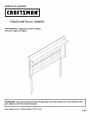
BACKWALL
WITH M ETAL PEGBOARD
CAUTION: Backwall MUST be attached to the Workbench
top is attached and the drawers are installed.
CAUTION:
before the
Read and follow all Safety Rules and Operating
Sears, Roebuck and Co., Hoffman Estates, IL 60179, USA.
Instructions
before first use of this product.
F1493
4
f
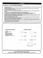
SAFETY WARNINGS
AND CAUTIONS:
Use appropriate safety equipment when using power and hand tools. Failureto do so may cause personal injuryor product damage.
Use adequate manpower when assembling and moving this unit. Failure to do so may cause personal injury or product damage.
DO NOT stand on this product. You may fall which may cause personal injury.
DO NOT mount this product on a truck bed or any other moving object. This may cause personal injuryor productdamage.
Appropriately secure this product before moving it with a forklift.
DO NOT tow with power equipment. The product could tip, which may cause personal injury or product damage.
DO NOT alter this product in any manner. This may cause product damage or personal injury.
Keep the product on level surfaces. The product may become unstable and tip if stored or moved on an un-level surface, which may
cause personal injury or product damage.
Be sure the workbench is flat on the floor before installing the Workbench Backwall. Failure to do so may cause personal injuryor
productdamage.
The maximum weight allowed to hang on or be in any way supported from the backwall is 65 pounds. If the limit is exceeded the
product may tip and cause personal injury or product damage.
Be sure to secure the Workbench Backwall to a studded or concrete wall. Failure to do so may cause the Workbench Backwall and
Workbench to become unstable and tip. This may cause personal injury or product damage.
Use only the provided pegboard on Workbench Backwall.
Backwallwith Metal Pegboard is only to be attached to one of the following Workbenches: 59741, 59742, 59746. Failure to do so
could result in personal injury or product damage.
r
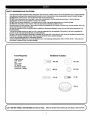
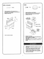
Tools
Hardware
Required:
Socket Wrench
7/16" Socket
Dnll
3/32" Drill Bit
1/8" Drill Bit
Screwdriver, Phillips
Screwdriver, Flathead
_[_
AA (16)
BB (3)
CC (2)
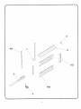
Included:
_--_)
_
DD (16)
EE (16)
FF (2)
GG (1)
(_,all 1-800-4MY-HOME
(1-800-469-4663)
for Service Parts.
Refer to Service Parts Drawing for full listing of Service Parts._
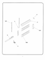
E
A(2)
F
D
\
\
C(2)
.....
G
\
\
:!:!:i:!::'
\
\
\
\
\
\,
B(2)
H
)
f
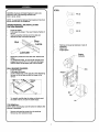
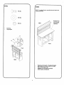
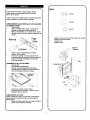
STEP1
f
WARNING: Backwallwith Metal Pegboard is only to be
attached to one of the following Workbenches:
59741, 59742, 59746
AA (2)
NOTE: To assemble the Backwall,the drawers and top must
first be removed from the workbench.
DD (2)
DRAWER REMOVAL AND INSTALLATION:
FRICTION DRAWERS:
•
•
•
Empty the drawer.
Fully extend the drawer. Then push it back a fraction of
an inch.
Insert a screwdriver into the slot in the slide and
depress the stop until it clears the lance.
Slot
f
Stop
Lance
EE (2)
Remove and reuse topfastenersinback
workbench.
Attach A(2).
Fingertighten.
of
Lubricate
__
Repeat the procedure for the other slide. Remove the
drawer.
To reinstallthe drawer, pry the stop far enough out to
engage the lance (3/16" to 1/4") and push the drawer
onto the slides until the stops pass over the lances.
BALL BEARING DRAWERS:
Empty the drawer.
•
Fully extend the drawer.
•
Lift the release lever on the rightside, while depressing
the lever on the left side and pullthe drawer out to
remove.
Existing
hardware
/
/
A(2)
FRONT
Lever
•
To reinstall, carefully align the slides and slowlypush
the drawer into the unit until the drawer stops.
TOP REMOVAL:
NOTE: When removing top, save the screws to reattach after
backwall is assembled.
Remove and save the screws from the wood top.
Remove top from workbench base.
J
F
F
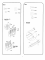
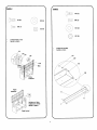
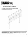
STEP 3
STEP2
AA(2)
DD (8)
BB (2)
BB {I)
©
EE (S)
DD (2)
©
•
EE (2)
Attach B(2) and C(2).
Finger tighten.
Assemble tray.
Finger tighten.
AA
/DD EE
/
BB
EE
DD
AA
Back
/
R,
\
Back
]
/
/
E
Wrench Tighten
fasteners from
step 1
Front
J
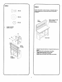
NOTE: To reattach the top, new pilot holes will need to be
marked and drilled.
AA (4)
DD (4)
\\
j
Reattach top
with existing
hardware
Back
EE (4)
/
/
¢
Install tray_
Finger tighten.
AA
\
DD
EE
i
/
Front
Front
Back
•
•
•
•
Place top on the bench in the desired location.
Mark centers of mounting holes to be drilled.
Drill 1/8" pilot holes in top.
Reattach top usingexisting hardware.
Wrench tighten all fasteners.
J
f
F
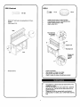
STEP 5 Continued
STEP6
(_._:_
CC (2)
GG (1)
FF (2)
Install grommet (GG) in desired location.
Place electrical cord for G through grommet.
Place G against bottom of tray.
Attach using FF(2).
Drill (2) 1/8" pilot holes in top using holes in C(2) as a
template.
Attach using CC(2).
Back
Place elecldcal
cordthrough
grommet.
/
hole
_'-MounUng
hole
\
CC
Fmnt
Screws and
washers
supplied
with H
Reinstall
Place H as desired.
Mark centers of 4 holes to be drilled.
Drill (4) 3132"pilot holes 1t2" deep.
Attach H using (4) screws and washers provided.
drawers.
r
•
•
•
J
Periodicallythe surfaces should be cleaned with a mild
detergent and water.
Auto wax will preserve the unit's luster finish. Apply the
wax as to a car. The wax will also help protect the unit
against scratches.
Grease and oil can be removed with most standard
cleaning fluids. For safety, use a nonflammable cleaning
fluid.
J
MANUAL DE USUARIO
TABLERO
METALICO
ADVERTENCIA:
Asegdrese de colocar
antes que la tapa y los cajones.
TRASERO
el tablero
ATENCION: Lea y siga todas las Normas de Seguridad y las Instrucciones de Funcionamiento
de utilizar por primera vez este producto.
antes
Sears, Roebuck and Co., Hoffman Estates, IL 60179, USA.
F1493
PRECAUCIONES
DE SEGURIDAD:
Cuando trabaje con electricidad o herramientas manuales, utilice un equipo de seguridad adecuado. Una averia puede causar daSos
personales o materiales.
Aseg_rese de utilizar las herramientas y piezas adecuadas cuando este montando o moviendo el producto. Una averia puede
producirdatlos personales o materiales.
NO se coloque encima del producto. Puede caerse y da_arse.
NO coloque el pmducto ni en una caravana ni en cualquier medio de transporte. Esto podrfa causar daCiospersonales o daflar el
producto.
Antes de movedo con una carretilla elevadora, aseg0rese de colocarlo adecuadamente.
NO Io arrastre con un equipo el_ctrico. El producto puede volcar y causar da_os personales o dafiar el producto.
NO modifique el producto de ninguna manera. Esto podrfa causar dar_ospersonales o daflar el producto.
Mantenga el producto en superficiesplanas. El producto puede ser inestable si se coloca o se mueve en una superficie que no sea
plana, Io que podrta causar dahos personales o daSar el producto.
AsegOrese de que el banco de trabajo este bien colocado en el suelo antes de instalar la parte de atr_s del tablero. Si no Io hace,
puede sufdr dattos personales o dar3arel objeto.
The maximum weight allowed to hang on or be in any way supported from the backwall is 65 pounds. If the limit is exceeded the
product may tip and cause personal injury or product damage.
AsegOrese de que el tablero del banco est_ atornillado a un pilaf o a una pared de camento. Si esto no se realiza adecuadamente, el
tablem trasero o el banco de trabajo pueden ser inestables o caerse. Esto pedrla causar dar3ospersonales o dafiar el producto.
$61o utilice el tablero que viene con el banco de trabajo.
El tablero met_lico trasero s61ose puede colocar en los siguientes modelos de bancos: 59741, 59742, 59746. De Io contrario pedda
ocasionarse lesiones personales o da_ar el producto.
f
Herramientas
necasarias:
Trinquete
Llave de tubo de 7/16"
Talladro
Broca de 3/32 de pulgada
Broca de 118de pulgada
Destomillador, philips
Destomillador, de cabeza plana
Ferreteria incluida:
BB (3)
CC(2)
_
!_
EE (16)
FF(2)
GG (1)
(
Llame al 1-800-659-7084 para Piezas de $ervicio.
Consulte el dibujo de piezas de servicio si desea un listado completo de piezas de servicio,
)
/
/
_D
•
ii_i
\\\
C(2)
G
\
\
\
\
\,
B(2)
'\
\
\
H
k,,
f-
f
PASO 1
ADVERTENCIA: El tablero met_lico trasero s61ose
puede colocar en los siguientes modalos de bancos:
59741, 59742, 59746.
AA (2)
AVISO: Para colocar el tablero trasero, en primer lugar debe
quitar los cajones y la tapa del banco de trabajo.
,i©
\./
COMO DESlNSTALAR
E INSTALAR LOS CAJONES:
CA JONES DE GUlA:
•
Vac|e el cajbn.
•
Saque completamente el cajbn. A continuacibn,
empOjeloun cent|metro aproximadamente.
Mete un destomillador por la ranura de uno de los
laterales y presione el tope hasta que pueda salir de
la gu[a.
Ranura
Tope
Guia
Saque y vulvar a usar los tornillossuperior en le parte
posterior de le banco trajajo.
Coloque A(2).
Apdete a mano.
Material
Existente
Lubricar
Repita el mismo procedimiento en el lateral
contrario. Quite el caj6n.
Para volver a colocar el caj6n ponga el tope Io
suficientemente lejos para coger la guia y empuje el
caj6n por los lados hasta Ilegar a los topes pot
encima de las gufas.
RODAMIENTO
DE LOS CA JONES:
•
Vacie el cajbn.
•
Quite el cajbn completamente.
•
Levante y suelte la palanca del lado derecho
mientras presiona la palanca del lateral izquierdo.
Ahora tire del cajbn hasta que Io saque.
__
_
oo<:>
/
-A(2)
Parte frontal
iiPalancade
beracion
EE
DD j
Para volver a instalar el caj6n, alinee
cuidadosamente los laterales y empuje el cajbn
despacio hasta que se pare.
COMO QUITAR LA TAPA:
AVISO: Guarde los tornillos y los ganchos cuando quite la
tapa para volver a colocarla una vez que haya pueste el
tablero trasero,
•
Saque los tomillos y ganchos de la tapa de madera.
•
Saque la tapa del banco de trabajo.
J
f
r
PASO 2
PASO3
AA (2)
AA(8)
BB (2)
BB (I)
EE (8)
_.._!
DD (2)
EE (2)
•
•
Coloque B(2) y C(2)
Apriete a mano.
Colocar la bandeja.
Apriete a mano.
•
AA
DD EE
EE
BB
J
DD
AA
B(2)
/
\
BB
/
Parte
Posterior
Parte
posterior
/
E
\
Apriete con Ilave
inglesa los cierres
desde el paso 1.
Parte frontal
/
/
(4)
NOTA: Para volver a colocar la tapa, se necesita marcar y
taladrar agujeros gufa nuevos para colocar los ganchos
existen_s.
DD (4)
©
•
•
Vuelva a colocarla parte
superiorutizando
el hardwareexistente
Parte
posterior
EE (4)
/
Instale la bandeja.
Apdete a mano.
AA
\
Parte frontal
EE
\
Parte
Frontal
Coloque la tapa de madera en el lugar del banco que se
desee.
Mark centers of mounting holes to be drilled.
Taladre agujeros guia de 1/8" en la tapa.
Suj6tela con la herramienta existente.
Apriete todos los tornilloscon una Ilave de tuercas.
Parte
Posterior
PASO 5 - Continuacibn
GG(1)
CC(2)
Taladre 2 agujeros de 1/8 de pulgada con una
profundidad de media pulgada en la tapa utilizando los
agujems de C(2) cornoplantilla.
Coloque usando CC(2).
Instale arandela en el lugar deseado.
Pase el cable el_tdco por G a trav_s de la arandela.
Coloque G contra la parte inferiorde la bandeja.
Coloque usando FF(2).
CC
Paseel cable
el_:trico a travL_s
de la
Back
Agujerode montaje
\
CC
Front
Con H se
suministran
tronillos y
arandelas.
Vuelva a colocar los cajones.
•
•
•
•
Coloque H como desee.
Marque los centros de 4 agujeros para postedormente
haosr los agujeros con el taladro.
Haga 4 agujeros piloto de 3/32 pulgadas y 1/2 pulgada de
profundidad.
Coloque H utilizando los (4) tomillos y arandelas que se
incluyen.
f
Deber_ limpiarpedbdicamente
jab6n suave.
Si Io encera, se ¢onservar_ el
cera de la misma manera que
tambi6n ayudar& a protegedo
la superficie con agua y
acabado final. Aplica la
a un coche. La cera
contra los araf_azos.
La grasa y el aceite se pueden limpiar con cualquier
producto de limpieza est&ndar. Para su seguddad no
utitios Ilquidos inflamables.
J