1
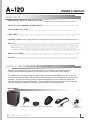
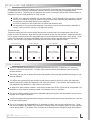
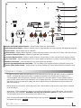
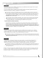
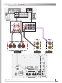
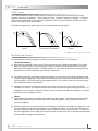
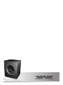
A-120
OWNER’S MANUAL
300 Watt Powered Subwoofer
12” E X T R A L O N G –T H R O W
Heavy Duty Woofer
F R E E - S TA N D I N G
POWERED SUBWOOFER
Presence
®
I M P O R TA N T SA F ET Y I N S T R U C T I O N S
Read these instructions.
Keep these instructions.
Heed all warnings.
Follow all instructions.
Do not use this apparatus near water.
Clean only with dry cloth.
Do not block any ventilation openings. Install in accordance with the manufacturer’s instructions.
Do not install near any heat sources such as radiators, heat registers, stoves, or other apparatus
(including amplifiers) that produce heat.
Do not defeat the safety purpose of the polarized or grounding-type plug. A polarized plug has two blades
with one wider than the other. A grounding type plug has two blades and a third grounding prong. The
wide blade or the third prong are provided for your safety. If the provided plug does not fit into your outlet,
consult an electrician for replacement of the obsolete outlet.
Protect the power cord from being walked on or pinched particularly at plugs, convenience receptacles, and
the point where they exit from the apparatus.
Only use attachments/accessories specified by the manufacturer.
Unplug this apparatus during lightning storms or when unused for long periods of time.
Refer all servicing to qualified service personnel. Servicing is required when the apparatus has been damaged in any way, such as power-supply cord or plug is damaged, liquid has been spilled or objects have
fallen into the apparatus, the apparatus has been exposed to rain or moisture, does not operate normally,
or has been dropped.
WARNING: To reduce the risk of fire or electric shock, this apparatus should not be exposed to rain or moisture and objects filled with liquids, such as vases, should not be placed on this apparatus.
To completely disconnect this equipment from the mains, disconnect the power supply cord plug from the
receptacle.
The mains plug of the power supply cord shall remain readily operable.
WA R N I N G
The lightning flash with arrowhead
symbol within an equilateral triangle, is intended
to alert the user to the presence of uninsulated
“dangerous voltage’’ within the product’s enclosure that may be of sufficient magnitude to
constitute a risk of electric shock to persons.
A-120
OWNER’S MANUAL
CAUTION
!
The exclamation point within an equilateral triangle is intended to alert the user to the
presence of important operating and maintenance
(servicing) instructions in the literature accompanying the product.
A-120
OWNER’S MANUAL
CONTENTS
I M P O R T A N T S A F E T Y I N S T R U C T I O N S 2
Y O U R A - 1 2 0 P O W E R E D S U B W O O F E R 2
AT T A C H I N G T H E F E E T 4
F E AT U R E S 4-5
C O N N E C T I O N 5-7
S E T U P 8 - 10
8
9
9 - 10
Placement
A-120 Controls
Fine Tuning the Controls
S P E C I F I C AT I O N S 10
N O T E S 11
YO U R A - 12 0 P OW E R E D S U BWO O F E R
Thank you for purchasing the A-120 powered subwoofer. Your subwoofer has been developed to
provide you with pleasing accurate bass in your music system or home theater sound system.
This manual covers operating procedures, general setup, and technical specifications for your A-120. We
recommend that you thoroughly read through the material contained in this manual before connecting your
subwoofer. This will ensure that you have a complete understanding of how to setup and operate your
subwoofer properly for optimum performance. Thank you again for choosing the A-120, and we hope that
you enjoy the enhanced dimension that a fine subwoofer adds to the sonic experience.
Box Contents:
Subwoofer
A-120
(4) Spiked Feet
OWNER’S MANUAL
(4) Knurled Lock Nuts
(4) Rubber Feet
Power Cord
Manual &
Warranty Card
AT TAC H I N G T H E F E ET
After reviewing the manual and unpacking your A-120 subwoofer, we suggest that the four rubber feet be installed
on the bottom of the enclosure to protect the subwoofer and your floor or cabinetry from damage during
installation and setup. These feet can be replaced by the spikes, or removed if desired, after the final location is
determined. Here are some guidelines for using the feet.
DO NOT try to slide your subwoofer with the feet installed. This will damage the foot supports or the feet.
If the A-120 is placed on carpet, the spikes are likely the best choice since they will penetrate the carpet and provide a solid and stable footing for the subwoofer.
If the unit is placed on a hard surface then the rubber feet should be used.
You may elect to use only three feet especially if the surface on which you are placing the subwoofer is
uneven, such as a stone or tile floor. See diagram for details.
To install the feet:
Thread the knurled jam nuts onto the desired feet and then screw the feet into the appropriate holes on the
bottom of the A-120 enclosure. Begin with the feet screwed all the way into the enclosure. Rotate the enclosure
into its upright position and lower the appropriate feet to level the subwoofer and prevent it from rocking. Finger
tighten the knurled jam nuts against the bottom of the enclosure to secure the feet and prevent them from
moving. Use care not to over-tighten the knurled jam nuts as they will be difficult to loosen.
Front of Subwoofer
Bottom of Subwoofer
Showing (4) Rubber Feet
Front of Subwoofer
Bottom of Subwoofer
Showing (3) Rubber Feet
Front of Subwoofer
Bottom of Subwoofer
Showing (4) Spiked Feet
Front of Subwoofer
Bottom of Subwoofer
Showing (3) Spiked Feet
F E AT U R E S
The A-120 subwoofer was designed for exceptional performance and value. It features a 12” extra-long
excursion woofer with high Bl motor. The bass reflex enclosure ensures extended bass response and high
acoustic efficiency.
The woofer is driven with an integral 300W class A/B amplifier utilizing the patented BASH technology for high
electrical efficiency.
The integral rear-mounted 300 watt amplifier includes several essential controls to contour the subwoofer’s
output to blend with virtually all loudspeakers and room environments. These controls, their operation, and
their adjustment are described in a later section of this manual.
An integral low pass crossover network is continuously-variable from 40Hz to 120Hz and can be bypassed if it is
preferable to use an external crossover located in an outboard receiver or processor.
The A-120’s integral amplifier incorporates a defeatable signal-sensing circuit that automatically powers up the
amplifier when a signal is detected.
A double-insulated isolated-ground electrical supply prevents electrical ground loops and reduces the noise floor
of the entire audio system.
The A-120 is shipped with 8 adjustable feet, (4 spiked and 4 rubber) with tool-less knurled jam nuts. These
feet can be installed in the bottom of the enclosure in either a three-point triangular pattern or more traditional
4 point square pattern. The bottom of the enclosure has 5 threaded inserts arranged to accept either pattern.
A-120
OWNER’S MANUAL
1
2
3
4
!
RISQUE DE CHOC ELETRIQUE
NE PAS OUVRIR
5
6
U.S. Patent #5,075,634
and
5,510,753 Patent
10
9
8
7
1 Power and Standby Mode Indicator – Off=No Power; Green=On; Red=Standby
2 Auto Power Mode Switch – Selects if amplifier power is signal activated; On=Signal Sensing, Off=Bypassed (Amp ON)
3 Level Control – Adjusts output level of subwoofer
4 Phase Control – Adjusts relative alignment of output signal with respect to the input; 0°=In Phase, 180°=Out of Phase
5 Crossover Frequency Control – Adjusts low pass filter cutoff frequency
6 Crossover Bypass Switch – Selects if internal crossover (low pass filter) is active; Variable=Active, Bypass=Inactive
7 Line Level Input – Input connection for RCA Line Level signals from processor or preamp; Includes LFE & Sub signals
8 Speaker Level Input – Input connection for High Level signals from amplifier
9 Power Input Receptacle and Fuse Holder – IEC 2-conductor 120V receptacle accepts supplied IEC power cord
10 Master (Main) Power Switch – Primary power; On=Power Enabled; OFF=Power disconnected from amplifier circuit
CONNECTION
No signal connection cable is provided with the A-120 subwoofer since the type and length of cable is installation
specific. A shielded RCA type coaxial cable, a shielded two-conductor wire with RCA type connectors, or a
2-channel speaker cable is required for connection of the A-120 to the audio system. Ensure sufficient length to
reach from the system source to the subwoofer’s line or speaker level input. If you are uncertain about the type
and length of wire to purchase after reading this section and the section on Placement then please contact your
dealer for assistance.
Before making any connections, ensure that power cord is disconnected or that the main power switch is switched
to the off position.
Input Signal: Follow the diagram on page 7 for connecting the subwoofer to your audio system. Use the option
that best suits your installation. WARNING: Use only one of the three options, (Do Not Combine Options).
The information below will aid in determining which option to use.
Note: The best performance can be achieved using the line level inputs ( OPTION 2 or OPTION 3 ) as opposed to
the speaker level inputs ( OPTION 1 ).
A-120
OWNER’S MANUAL
CONNECTION
(continued)
OPTION 1
If a Line Level signal, (Stereo Left/Right, LFE, Sub Out, etc) is available then skip to options 2 and 3 to see if
they are more appropriate for your installation.
If no line level output signal is available then the subwoofer should be connected in parallel with the main
speakers per the Option 1 drawing. A description is provided below.
Per the Option 1 drawing on the adjacent page, use two 2-condcutor speaker cables and connect the
left and right front speaker outputs of your receiver or amplifier to the Speaker Level inputs of the A-120
as you would connect a pair of speakers. Use care to ensure that the proper polarity is observed (R+ is
connected to R+ of A-120, R- is connected to R- of A-120, etc). Failure to do so will result in little to no
subwoofer output or erratic output.
If a (B) speaker output is available (unutilized) it can be used in place of making a parallel connection
at the receiver but this will only work if the amplifier utilizes an internal parallel connection of the
(A) and (B) speaker pairs. Use the following test to determine if this is the case.
Test for Parallel (A) and (B) connection:
Ensure that a pair of speakers is connected to the (A) output and that nothing is connected to the (B)
speakers. Engage the (B) speaker button while an audio source is playing through the (A) speakers. If
the (A) speakers continue to play then the connections are parallel and you may use the (B) output for the
subwoofer. If the (A) speakers discontinue playing when the (B) button is engaged then you will need to
connect the subwoofer in parallel to the (A) speaker outputs.
OPTION 2
If an LFE (Low Frequency Effect) or Subwoofer output is available then skip to Option 3 since it will likely
produce the best results. If no LFE output is available and a line level Front Channel Output or Preamplifier
Output is available, then this (Option 2) is the preferred method of connection.
Per the Option 2 drawing on the adjacent page, use a stereo RCA style (patch) cable and connect the left
and right line level (RCA style) front channel outputs of your receiver or preamplifier/processor to the Left/
Right Line Level inputs of the A-120.
OPTION 3
If the subwoofer is connected to a modern home theater receiver or processor with an available LFE or
Subwoofer output then this option will likely produce the best results. If no LFE or Subwoofer output is
available but a line level Front Channel Output or Preamplifier Output is available, then use Option 2.
Per the Option 3 drawing on the adjacent page, use a single RCA style (patch) cable and connect the line
level (RCA style) LFE or Subwoofer output of your receiver or preamplifier/processor to the Left/LFE Line
Level input of the A-120.
AC Power: The unit is shipped with a standard IEC AC cable. Remove this cable from its packaging and insert
the cord into the IEC receptacle on the back of the subwoofer. It is best to connect power only after all other
connections are made. Connect the power cord to an AC wall receptacle or similar.
A-120
OWNER’S MANUAL
CONNECTION
(continued)
VIDEO
PRE OUT
SINGLE
AUDIO
CENTER
VIDEO
L
S-VIDEO
R
IN
ANTENNA
OUT
DVD
CD
DVD
IN
VCR
VCR
OUT
FRONT A
L
AM
R
FRONT SURROUND.
SPEAKERS
SURROUND
CENTER
L
R
SUR.
BACK
SUB
WOOFER
SURROUND BACK / BI-AMP
R
L
AC OUTLETS
GND
FM
75 Ω
UNBAL
REMOTE
OUT
SPEAKERS
FRONT A
L
PRE OUT
SINGLE
R
CENTER
L
R
FRONT SURROUND.
SUB
WOOFER
SUR.
BACK
Line Level
input
Line Level
input
Speaker Level Input
Left/
LFE
Left/
LFE
Right
Right
Right
Left
OPTION 1
OPTION 2
OPTION 3
!
A-120
OWNER’S MANUAL
SETUP
Placement
There are a number of factors, both acoustic and aesthetic, that ultimately determine the best loudspeaker
placement. Subwoofers, by nature of the frequency range in which they operate, have their own challenges,
which have as much to do with the room acoustics and listening position as anything else. In many cases the
designated location may already be chosen and the only available adjustments may be the subwoofer’s controls.
The A-120 controls will allow you to make the best of virtually any installation. If you feel uncomfortable with
setting up your A-120 after reading through this section then you should consider enlisting the help of an
experienced person or contacting your dealer.
Below are a some generalized rules for understanding the acoustic nature of low frequency sound reproduction in
an average residential listening room. These rules will aid in the placement and tuning of your A-120 subwoofer.
If possible, experiment with the placement of your A-120 to determine what works best in your listening room.
Most rooms have significant resonant modes at low frequencies. The listener will experience these resonant
modes as a variation in the intensity of certain frequencies at different locations within the room. Resonant
modes are the result of reflected acoustic energy interacting within a room’s boundaries. The resonant modes
can produce large errors in the frequency response and reduce the overall enjoyment of the audio reproduction.
Equalization cannot simultaneously compensate for all locations within a room. However, physical elements
within or at the room’s boundaries can effectively improve the room’s behavior. Subwoofer placement also has
an effect on the excitation of the resonant modes and the way they are experienced. Contacting an expert
in the field of acoustics can be worthwhile if one finds that the low frequency reproduction in their room is
unsatisfactory or if one wants assistance in optimizing their installation.
Placing a subwoofer on the floor near a wall will increase its radiating power by as much as 2X. Placing a
subwoofer on the floor near the intersection of two walls (a corner) will increase its radiating power by as much
as 4X. Corner loading, as it is sometimes called, is an excellent way to get bass extension and greater acoustic
output from a subwoofer especially at very low frequencies.
In the same way that the subwoofer’s output is augmented by a corner, the listening position can also have a
significant effect on how the bass is experienced. Sitting at a room’s boundary, such as near the back wall of a
room, will significantly increase the bass level across much of the low frequency spectrum.
Placing a subwoofer close to the listening position (less than 5ft (1.5m)) can increase the intensity of the
transients and reduce the acoustic power demands from the subwoofer in some installations. In others, it can
increase the power demands if the woofer is placed at a primary node. Placing a subwoofer(s) close to the
listening position can also create more tactile sensation.
Bass frequencies below about 80Hz are considered to be omnidirectional and tend to have no localization. That
is to say that it is difficult to determine their place of origin. For this reason, placement of most subwoofers is
not limited to the front of the room. However, in practice this is not always the case. There are cues such as
tactile and audible vibration and higher frequency signal content that can suggest the direction of the source.
For this reason it may be desirable to locate the subwoofer(s) at the front of the room. It may also be necessary
to reduce the crossover frequency below 80Hz if one finds that the bass sounds too detached from the other
sound sources.
Placing a subwoofer(s) at the back of the room is also a consideration especially if placement of a subwoofer at
the front of the room is not suitable or produces poor results. Placement directly behind or beside the listening
position can produce very good results as well as corner loading in the back of the room. Other options include
placing the subwoofer(s) on the side(s) of the room especially when multiple woofers are used. If possible
experiment with different positions. Don’t exclude the possibilities of locating your subwoofer in walls, ceilings,
floors, or underneath, beside, and behind furniture.
Symmetrically or asymmetrically locating two or more woofers in the room can be done to reduce room mode
effects and to balance the localization of the sound.
It is not necessary to direct the front of a subwoofer at the listening position.
A-120
OWNER’S MANUAL
S E T U P (continued)
A-120 Controls
The A-120 subwoofer has thee variable controls for tailoring its output to the room and to the primary
speakers (also known as satellites). These controls are Level, Crossover Frequency, and Phase. The control
with the most audible effect is the Level control, followed by the Crossover Frequency, and then the Phase
control, which has the least audible effect.
The following legend shows graphically how each control affects the audio signal.
SPL
(d B )
SPL
(d B )
F re q u e n cy (H z)
Level
SPL
(d B )
F re q u e n cy (H z)
Crossover Frequency
P h a se (D e g re e s)
Phase
Note: SPL is “Sound Pressure Level” (Volume)
Fine Tuning the Controls
We recommend the following method as a starting point for fine tuning the A-120 subwoofer.
Level and Frequency
A) Begin with the subwoofer’s Level control all the way down and the Frequency adjustment set to 120Hz.
With the Frequency control in this position the woofer will output higher frequencies that will likely be
duplicated by the satellite speakers. “Satellite speakers” is a term used to describe the primary listening
speakers that cover the frequency range above the subwoofer’s.
B) Use familiar music with strong bass content and increase the Level control until the bass passages sound
robust or slightly exaggerated. Then reduce the Frequency control to blend the subwoofer with your main
system speakers. We have found that most speakers with 6” to 8” woofers blend well with the crossover
set somewhere between 50Hz and 80Hz.
C) Readjust the Level and the Frequency controls (up or down) as necessary until the bass sounds full,
extended, and natural. Use multiple musical pieces to test the system while fine tuning the controls. If it
sounds like your subwoofer is always producing the same bass note with different recordings it is possible
that the bass level is adjusted too high.
Phase
A) When adjusting the phase, use familiar music with strong bass content. The phase adjustment primarily
affects the frequencies where the subwoofer and the satellite speakers overlap (frequencies near the
crossover frequency).
B) Rotate the phase across its range and listen to the balance and strength of the mid-bass frequencies. Tune
the phase adjustment so that these frequencies are detailed and distinct. If they become overly strong it
may be necessary to reduce the subwoofer’s crossover frequency and/or input level a little. The effect of
the phase adjustment can be subtle and it may be necessary to take some time to become acquainted with
the sound before changing the adjustment.
A-120
OWNER’S MANUAL
S E T U P (continued)
Fine Tuning the Controls
(continued)
Crossover Switch
If you choose to bypass the internal crossover and use an external crossover, such as those located in most
modern receivers and processors, then you will need to fine tune the system based on the adjustments
provided by the manufacturer of your electronics in conjunction with the Level and Phase controls on the
A-120. Note, the Level and Phase adjustments on the A-120 are not bypassed and will still function as
indicated above.
To bypass the internal crossover, move the Crossover switch 6 to the Bypass position. The subwoofer will
now pass signals up to approximately 300Hz.
Auto Power Mode Switch
The A-120 contains a circuit that automatically powers up the amplifier when a signal is detected. The
same circuit also places the A-120 into standby mode when no signal has been detected for a period of
approximately 10 minutes. This signal sensing circuit can be bypassed by switching the Auto switch 2 to
the OFF position if it is preferable to control the A-120’s power with a remotely operated power source.
S P E C I F I C AT I O N S
Frequency Response: Crossover Frequency:
Phase Adjustment:
Amplifier Output Power:
Audio Inputs:
Input Impedance:
Input Power: Input Power Connection:
Power (Mains) Fuse:
Power Modes:
Auto Off Delay:
Dimensions: Weight:
Shipping Dimensions:
Shipping Weight:
A-120
OWNER’S MANUAL
28Hz – 300Hz (System Response)
40Hz – 120Hz (Low-pass filter with bypass switch)
0 – 180 degrees (Continuously variable)
300 watts, with thermal and clipping limiters
Summing stereo line level (RCA x2)
LFE (RCA shared with Left input connector)
Speaker level (Stereo 5-way binding post)
Line Level – 20k ohms, Unbalanced
Speaker Level – 220 ohms
120V 60Hz AC
IEC 2-wire receptacle with integral fuse holder
3.15A 250V T3.15AL (5x20mm) style Slow Blow
Auto signal sensing and always on
~10 minutes
15-3/8"W x 17-5/16"H x 14-3/4"D, (390W x 440H x 375D)mm (without feet)
43lbs (19.5kg)
21"W x 20"H x 20"D, (533W x 508H x 508D)mm
51lbs (23.2kg)
10
NOTES
A-120
OWNER’S MANUAL
11
Rev. G
Note: Specifications are subject to change without notice.
For the most up to date manual information please check our website.