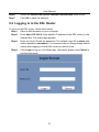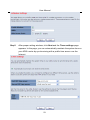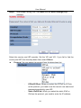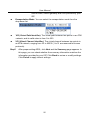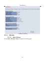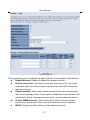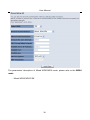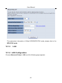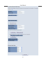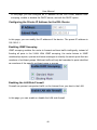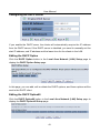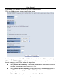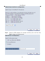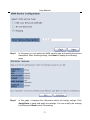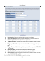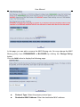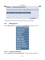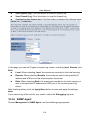
1
USER MANUAL ADSL2 BarricadeTM N 11n Wireless 4-Port ADSL2/2+ Modem Router SMC7904WBRA-N2 SMC7904WBRA-N2 User Manual User Manual Contents 1 Compliances ...................................................................................................... 1 1.1 Europe – EU Declaration of Conformity ........................................................ 1 2 Safety Precautions ............................................................................................. 5 3 Précautions de sécurité...................................................................................... 6 4 Sicherheitsmaßnahmen ..................................................................................... 7 5 Precauciones de seguridad................................................................................ 8 6 Precauções de Segurança ................................................................................. 9 7 Overview .......................................................................................................... 10 7.1 Packing List ................................................................................................. 10 7.2 Application ................................................................................................... 10 7.3 Features ...................................................................................................... 11 7.4 8 Standards Compatibility and Compliance .................................................... 12 Hardware Description and Installation ............................................................. 12 8.1 Hardware Description .................................................................................. 12 8.1.1 Front Panel .................................................................................................. 12 8.1.2 Rear Panel ................................................................................................... 14 8.2 Hardware Installation ................................................................................... 15 8.2.1 Choosing the Best Location for Wireless Operation .................................... 15 8.2.2 9 Connecting the Router ................................................................................. 15 PC Network Configuration and Login ............................................................... 17 9.1 PC Network Configuration ........................................................................... 17 9.2 Logging In to the DSL Router ...................................................................... 19 10 Web-Based Management ................................................................................ 20 10.1 Start ............................................................................................................. 22 10.1.1 Wizard Setup ....................................................................................... 22 10.1.2 Wireless ............................................................................................... 26 10.1.3 LAN...................................................................................................... 40 10.1.4 10.2 LAN Configuration ............................................................................... 40 Advanced Setup .......................................................................................... 45 10.2.1 Layer2 Interface................................................................................... 46 10.2.2 WAN Service ....................................................................................... 48 10.2.3 NAT ...................................................................................................... 72 i User Manual 10.2.4 Security................................................................................................ 76 10.2.5 Parental Control................................................................................... 80 10.2.6 Quality of Service ................................................................................ 82 10.2.7 Routing ................................................................................................ 86 10.2.8 DNS ..................................................................................................... 90 10.2.9 DSL...................................................................................................... 91 10.2.10 UPnP ................................................................................................... 92 10.2.11 DNS Proxy ........................................................................................... 93 10.2.12 Storage Service ................................................................................... 94 10.2.13 Interface Grouping ............................................................................... 95 10.2.14 Multicast .............................................................................................. 98 10.2.15 10.3 Wireless ............................................................................................... 98 Management .............................................................................................. 105 10.3.1 Passwords Settings ........................................................................... 105 10.3.2 Internet Time...................................................................................... 106 10.3.3 Diagnostics ........................................................................................ 107 10.3.4 Settings.............................................................................................. 108 10.3.5 System Log........................................................................................ 109 10.3.6 SNMP Agent ...................................................................................... 110 10.3.7 TR-69 Client .......................................................................................111 10.3.8 Access Control- Services .................................................................. 112 10.3.9 Update Software ................................................................................ 114 10.3.10 10.4 Reboot ............................................................................................... 114 Device Information ..................................................................................... 115 10.4.1 Summary ........................................................................................... 115 10.4.2 WAN .................................................................................................. 117 10.4.3 Statistics ............................................................................................ 117 10.4.4 LAN.................................................................................................... 117 10.4.5 WAN Service ..................................................................................... 118 10.4.6 xTM.................................................................................................... 118 10.4.7 xDSL .................................................................................................. 118 10.4.8 Route ................................................................................................. 120 10.4.9 ARP ................................................................................................... 120 10.4.10 DHCP ................................................................................................ 120 11 Q&A................................................................................................................ 122 ii User Manual 1 Compliances 1.1 Europe – EU Declaration of Conformity This device complies with the essential requirements of the R&TTE Directive 1999/5/EC. The following test methods have been applied in order to prove presumption of conformity with the essential requirements of the R&TTE Directive 1999/5/EC: - EN 60950-1:2006 + A11: 2009 Safety of Information Technology Equipment. - EN 300 328 V1.7.1: 2006-10 Electromagnetic compatibility and Radio spectrum Matters (ERM); Wideband transmission systems; Data transmission equipment operating in the 2,4 GHz ISM band and using wide band modulation techniques; Harmonized EN covering essential requirements under article 3.2 of the R&TTE Directive. - EN 301 489-17 V1.8.1/ 2008-04 EN 301 489-17 V2.1.1/ 2009-05 Electromagnetic compatibility and Radio spectrum Matters (ERM); Electromagnetic Compatibility (EMC) standard for radio equipment and services; Part 17: Specific conditions for 2.4 GHz wideband transmission systems and 5 GHz high performance RLAN equipment. - EN 62311: 2008 Assessment of electronic and electrical equipment related to human exposure restrictions for electromagnetic fields (0 Hz - 300 GHz). This device is a 2.4 GHz wideband transmission system (transceiver), intended for use in all EU member states and EFTA countries, except in France and Italy where restrictive use applies. In Italy the end-user should apply for a license at the national spectrum authorities in order to obtain authorization to use the device for setting up outdoor radio links and/or for supplying public access to telecommunications and/or network services. This device may not be used for setting up outdoor radio links in France and in some areas the RF output power may be limited to 10 mW EIRP in the frequency range of 2454 – 2483.5 MHz. For detailed information the end-user should contact the national spectrum authority in France. 1 User Manual This equipment may be operated in: The official CE certificate of conformity can be downloaded by selecting the relevant model/ part number from www.smc.com -> support -> download. Български [Bulgarian] С настоящето, SMC Networks декларира, че това безжично устройство е в съответствие със съществените изисквания и другите приложими разпоредби на Директива 1999/5/EC. Česky [Czech] SMC tímto prohlašuje, že tento Router je ve shodě se základními požadavky a dalšími příslušnými ustanoveními směrnice 1999/5/ES. Dansk [Danish] Undertegnede SMC erklærer herved, at følgende udstyr Router overholder de væsentlige krav og øvrige relevante krav i direktiv 1999/5/EF. Nederlands [Dutch] English Hierbij verklaart SMC dat het toestel Router in overeenstemming is met de essentiële eisen en de andere relevante bepalingen van richtlijn 1999/5/EG. Hereby, SMC, declares that this Router is in compliance with the essential requirements and other relevant provisions of Directive 1999/5/EC. Estonian Eesti Käesolevaga kinnitab SMC seadme Router vastavust direktiivi 1999/5/EÜ põhinõuetele ja nimetatud direktiivist tulenevatele teistele asjakohastele sätetele. Finnish Suomi SMC vakuuttaa täten että Router tyyppinen laite on direktiivin 1999/5/EY oleellisten vaatimusten ja sitä koskevien direktiivin muiden ehtojen mukainen. 2 User Manual French Français Par la présente SMC déclare que l'appareil Router est conforme aux exigences essentielles et aux autres dispositions pertinentes de la directive 1999/5/CE. German Deutsch Hiermit erklärt SMC, dass sich das Gerät Router in Übereinstimmung mit den grundlegenden Anforderungen und den übrigen einschlägigen Bestimmungen der Richtlinie 1999/5/EG befindet. Greek Ελληνική ΜΕ ΤΗΝ ΠΑΡΟΥΣΑ SMC ΔΗΛΩΝΕΙ ΟΤΙ Router ΣΥΜΜΟΡΦΩΝΕΤΑΙ ΠΡΟΣ ΤΙΣ ΟΥΣΙΩΔΕΙΣ ΑΠΑΙΤΗΣΕΙΣ ΚΑΙ ΤΙΣ ΛΟΙΠΕΣ ΣΧΕΤΙΚΕΣ ΔΙΑΤΑΞΕΙΣ ΤΗΣ ΟΔΗΓΙΑΣ 1999/5/ΕΚ. Hungarian Magyar Alulírott, SMC nyilatkozom, hogy a Router megfelel a vonatkozó alapvetõ követelményeknek és az 1999/5/EC irányelv egyéb elõírásainak. Italian Italiano Con la presente SMC dichiara che questo Router è conforme ai requisiti essenziali ed alle altre disposizioni pertinenti stabilite dalla direttiva 1999/5/CE. Latviski [Latvian] Ar šo SMC deklarē, ka Router atbilst Direktīvas 1999/5/EK būtiskajām prasībām un citiem ar to saistītajiem noteikumiem. Lithuanian Lietuvių Šiuo SMC deklaruoja, kad šis Router atitinka esminius reikalavimus ir kitas 1999/5/EB Direktyvos nuostatas. Maltese Malti Hawnhekk, SMC, jiddikjara li dan Router jikkonforma mal-ħtiġijiet essenzjali u ma provvedimenti oħrajn relevanti li hemm fid-Dirrettiva 1999/5/EC. Polish Polski Niniejszym SMC oświadcza, że Router jest zgodny z zasadniczymi wymogami oraz pozostałymi stosownymi postanowieniami Dyrektywy 1999/5/EC. Portuguese SMC declara que este Router está conforme com os requisitos essenciais e outras disposições da Directiva 1999/5/CE. Português 3 User Manual Romanian Romană SMC Networks declară că acest dispozitiv fără fir respectă cerinţele esenţiale precum şi alte dispoziţii relevante ale Directivei 1999/5/EC. Slovak SMC týmto vyhlasuje, že Router spĺňa základné požiadavky a všetky príslušné ustanovenia Smernice 1999/5/ES. Slovensky Slovenian Slovensko SMC izjavlja, da je ta Router v skladu z bistvenimi zahtevami in ostalimi relevantnimi določili direktive 1999/5/ES. Spanish Español Por medio de la presente SMC declara que el Router cumple con los requisitos esenciales y cualesquiera otras disposiciones aplicables o exigibles de la Directiva 1999/5/CE. Swedish Svenska Härmed intygar SMC att denna Router står I överensstämmelse med de väsentliga egenskapskrav och övriga relevanta bestämmelser som framgår av direktiv 1999/5/EG. Turkish Turk SMC Networks bu kablosuz cihazın temel gereksinimleri ve 1999/5/EC yonergesindeki ilgili koşulları karşıladığını beyan eder. 4 User Manual 2 Safety Precautions Read the following information carefully before operating the device. Please follow the following precaution items to protect the device from risks and damage caused by fire and electric power: Use the power adapter that is included with the device package. Pay attention to the power load of the outlet or prolonged lines. An overburdened power outlet or damaged cords and plugs may cause electric shock or fire. Check the power cords regularly, if you find any damage, replace it at once. Proper space for heat dissipation is necessary to avoid any damage caused by device overheating. The ventilation holes on the device are designed for heat dissipation to ensure that the device works normally. Do not cover these ventilation holes. Do not put this device close to a place where a heat source exits or high temperature occurs. Avoid placing the device in direct sunshine. Do not put this device close to a place which is damp or wet. Do not spill any fluid on this device. Please follow the instructions in the user manual/quick install guide carefully to connect the device to your PC or other electronic product. Any invalid connection may cause a power or fire risk. Do not place this device on an unstable surface or support. 5 User Manual 3 Précautions de sécurité Lisez attentivement les informations suivantes avant d’utiliser votre appareil. Respectez toutes les précautions afin de protéger l’appareil des risques et dégâts provoqués par un incendie et l’alimentation électrique : • • • • • • • Utilisez exclusivement l’adaptateur d’alimentation fourni avec cet appareil. Faites attention à la puissance de charge de la prise de courant ou des rallonges électriques. Une prise surchargée ou des cordons et des fiches endommagés peuvent provoquer une électrocution ou un incendie. Vérifiez régulièrement votre câble électrique. Si vous constatiez le moindre défaut, remplacez-le immédiatement. Il est primordial de laisser suffisamment d’espace autour de l’appareil pour permettre la dissipation de la chaleur et éviter les dégâts provoqués par une surchauffe de l’appareil. Les orifices de ventilation de l’appareil sont conçus pour permettre la dissipation thermique et garantir le bon fonctionnement de l’appareil. Ne couvrez jamais ces orifices. Ne placez pas cet appareil à proximité d’une source de chaleur ou dans un endroit exposé à des températures élevées. Evitez également de l’exposer à la lumière directe du soleil. Ne placez pas cet appareil à proximité d’un lieu humide ou mouillé. Prenez garde à ne renverser aucun liquide sur cet appareil. Merci de suivre les instructions du manuel d'utilisateur / guide d’installation rapide attentivement pour connecter l'appareil à votre PC ou à tout autre produit électronique. Toute connexion non valide peut provoquer un problème électrique ou un risque d'incendie. Ne placez pas cet appareil sur une surface ou un support instable. 6 User Manual 4 Sicherheitsmaßnahmen Lesen Sie vor der Inbetriebnahme des Gerätes aufmerksam die nachstehenden Informationen. Bitte befolgen Sie die nachstehenden Sicherheitsmaßnahmen, damit das Gerät nicht beschädigt wird oder Gefahren durch Brand oder elektrische Energie entstehen: • • • • • • • Verwenden Sie nur das beim Gerät mitgelieferte Netzteil. Achten Sie auf die Last der Steckdose oder des Verlängerungskabels. Eine überlastete Steckdose oder beschädigte Kabel und Stecker können Stromschläge und Brand verursachen. Prüfen Sie die Netzkabel regelmäßig. Ersetzen Sie sie umgehend, falls sie beschädigt sind. Achten Sie zur Vermeidung von Geräteschäden aufgrund von Überhitzung darauf, dass genügend Freiraum zur Wärmeabfuhr vorhanden ist. Die Belüftungsöffnungen am Gerät dienen der Wärmeabfuhr und damit der Gewährleistung eines normalen Gerätebetriebs. Decken Sie diese Belüftungsöffnungen nicht ab. Stellen Sie dieses Gerät nicht in der Nähe von Wärmequellen oder an Orten mit hohen Temperaturen auf. Platzieren Sie das Gerät nicht im direkten Sonnenlicht. Stellen Sie dieses Gerät nicht an feuchten oder nassen Orten auf. Achten Sie darauf, keine Flüssigkeiten über dem Gerät zu verschütten. Befolgen Sie die Hinweise im Benutzerhandbuch (bzw. in der Kurzanleitung) zum Anschluß des Gerätes an einen PC oder ein anderes Elektrogerät. Jegliche unzulässige Verbindung birgt die Gefahr von Stromschlägen und Brandgefahr. Platzieren Sie dieses Gerät nicht auf einer instabilen Oberfläche oder Halterung. 7 User Manual 5 Precauciones de seguridad Lea la siguiente información detenidamente antes de utilizar el dispositivo. Siga las indicaciones de precaución que se mencionan a continuación para proteger el dispositivo contra riesgos y daños causados por el fuego y la energía eléctrica: • • • • • • • Utilice el adaptador de alimentación incluido en el paquete del dispositivo. Preste atención a la carga de potencia de la toma de corriente o de los alargadores. Una toma de corriente sobrecargada o líneas y enchufes dañados pueden provocar descargas eléctricas o un incendio. Compruebe los cables de alimentación con cierta frecuencia. Si detecta algún daño, reemplácelos inmediatamente. Deje un espacio adecuado para que se disipe el calor y evitar así cualquier daño en el dispositivo causado por sobrecalentamiento. Los orificios de ventilación del dispositivo están diseñados para disipar el calor y garantizar que dicho dispositivo funciona con normalidad. No tape estos orificios de ventilación. No coloque este dispositivo cerca de un lugar donde haya una fuente de calor o temperaturas elevadas. Evite exponer el dispositivo a la luz solar directa. No coloque este dispositivo junto a un lugar húmedo o mojado. No derrame ningún fluido sobre el dispositivo. Por favor, siga cuidadosamente las instrucciones que figuran en el manual/guía de instalación rápida para conectar el dispositivo a su PC o a cualquier otro producto electrónico. Cualquier conexión no válida podría causar riesgo de descarga o de incendio. No coloque este dispositivo en una superficie o soporte inestable. 8 User Manual 6 Precauções de Segurança Leia atentamente as seguintes informações antes de utilizar o dispositivo. Respeite as seguintes indicações de segurança para proteger o dispositivo contra riscos e danos causados por fogo e energia eléctrica: • • • • • • • Utilize o transformador incluído na embalagem do dispositivo. Respeite a potência da tomada eléctrica e das extensões. Uma tomada eléctrica sobrecarregada ou cabos e fichas danificadas podem causar choques eléctricos ou fogo. Verifique regularmente os cabos de alimentação. Caso algum se encontre danificado, substitua-o imediatamente. É necessário deixar algum espaço livre em volta do dispositivo para dissipação de calor, de forma a evitar danos causados pelo sobreaquecimento do dispositivo. Os orifícios de ventilação do dispositivo foram concebidos para dissipar o calor e assegurar que o mesmo funciona normalmente. Não bloqueie esses orifícios de ventilação. Não coloque este dispositivo junto a fontes de calor ou em locais com temperaturas elevadas. Evite colocar o dispositivo sob luz solar directa. Não coloque este dispositivo junto a locais molhados ou com humidade. Não derrame líquidos sobre o dispositivo. Por favor siga atentamente as instruções do manual / guia de instalação rápida para conectar o dispositivo ao seu PC ou a qualquer outro dispositivo electrónico. Atenção que qualquer tipo de ligação inválida pode originar risco de choque eléctrico ou de incêndio. Não coloque este dispositivo numa superfície ou suporte instáveis. 9 User Manual 7 Overview The SMC7904WBRA-N2 Router is an ADSL2+ Integrated Access Device. It provides four 10/100Base-TX Ethernet interfaces at the user end. The Router provides a high-speed ADSL broadband connection to the Internet or Intranet for high-end users, such as net bars and office users. It provides high-performance access to the Internet, with downstream speeds up to 24 Mbps. The Router supports WLAN access. It complies with IEEE 802.11b/g and 802.11n standards, and WEP, WPA, and WPA2 security specifications. The WLAN of the Router supports a two-transmit, two-receive (2T2R) antenna configuration. 7.1 Packing List SMC7904WBRA-N2 ADSL splitter Switching AC power adapter Ethernet cable (RJ-45) 2 Telephone cables (RJ-11) Quality Warranty Card Quick Installation Guide (QIG) GPL Notice CD; includes User Manual and GPL source code 7.2 Application Home gateway SOHOs Small enterprises High data rate broadband sharing Audio and video streaming and transfer PC file and application sharing Network and online gaming 10 User Manual 7.3 Features User-friendly GUI for web configuration Several pre-configured popular games. Just enable the game support and the port settings are automatically configured. Compatible with all standard Internet applications Industry-standard and interoperable DSL interface Simple web-based status page displays a snapshot of system configuration, and links to the configuration pages Downloadable flash software updates Support for up to 8 permanent virtual circuits (PVCs) Support for up to 8 PPPoE sessions Support for RIP v1 and RIP v2 WLAN with high-speed data transfer rates of up to 130 Mbps, compatible with IEEE 802.11b/g/n, 2.4 GHz compliant equipment Optimized Linux 2.6 Operating System IP routing and bridging Asynchronous transfer mode (ATM) and digital subscriber line (DSL) support Point-to-point protocol (PPP) Network/port address translation (NAT/PAT) Quality of Service (QoS) Wireless LAN security: WPA, 802.1X, RADIUS client Universal plug-and-play (UPnP) File server for network attached storage (NAS) devices Print server Web filtering Management and control - Web-based management (WBM) - Command line interface (CLI) - TR-069 WAN management protocol Remote update USB mass-storage, SAMBA and DLNA System statistics and monitoring DSL router is targeted at the following platforms: DSL modems, wireless access points and bridge. 11 User Manual 7.4 Standards Compatibility and Compliance Support s application level gateway (ALG) ITU G.992.1 (G.dmt) ITU G.992.2 (G.lite) ITU G.994.1 (G.hs) ITU G.992.3 (ADSL2) ITU G.992.5 (ADSL2+) ANSI T1.413 Issue 2 IEEE 802.3 IEEE 802.3u IEEE 802.11b IEEE 802.11g IEEE 802.11n 8 Hardware Description and Installation 8.1 Hardware Description 8.1.1 Front Panel Figure 1 Front Panel The following table describes the indicators on the front panel. Indicator Color Status Description Power Green On Red On Off DSL Green The device is powered on and operating normally. The device has detected a self-test failure or other malfunction. The device is powered off. On DSL link has been established. Slow Blink No DSL link detected. Fast Blink Off DSL link detected. The device is powered off. 12 User Manual Indicator Color Green Internet Red Status On Green Data is being transmitted. Authentication has failed. Blink Off WLAN Green Transmitting or receiving data over the Ethernet link. No Ethernet link established. Blink Transmitting or receiving data over the WLAN. Green Blink Off Green down. An Ethernet link is established. The WLAN is enabled. On USB No PPP connection or the PPP connection is On Off WPS up). On On 1/2/3/4 There is a connection to the Internet (PPP is Blink Off LAN Description On Off The WLAN is disabled. A Wi-Fi Protected Setup connection has been successfully established. Wi-Fi Protected Setup is setting up a connection. Wi-Fi Protected Setup is idle. A USB device is connected. No USB device is connected. 13 User Manual 8.1.2 Rear Panel Figure 2 Rear panel The following table describes the interfaces and buttons on the rear panel. Interface Description Line WLAN Reset WPS LAN 4~1 USB Power RJ-11 port for connecting to the ADSL interface or a splitter through a telephone cable. WLAN switch for enabling or disabling the WLAN function. Press the button for at least 3 seconds and then release it. System restores the factory default settings. Enables WPS PBC mode. When WPS is enabled, press this button for the wireless router to start the negotiation of PBC mode. RJ-45 ports for connecting the router to PCs or other network devices. USB host port for connection to a USB device to support a specific value-added application. For connecting the AC power adapter to supply 12 V DC, 1 A. Power on/off switch, next to the power socket. Warning: Do not press the Reset button unless you want to clear the current settings. The Reset button is in a small circular hole on the rear panel. If you want to restore the default settings, press the Reset button for 3 seconds with a fine needle inserted into the hole and then release the button. The system reboots and returns to the factory defaults. The power specification is 12V, 1A. If the power adapter does not match the specification, it may damage the device. 14 User Manual 8.2 Hardware Installation 8.2.1 Choosing the Best Location for Wireless Operation Many environmental factors may affect the effective wireless function of the DSL Router. If this is the first time that you have set up a wireless network device, read the following information: The access point can be placed on a shelf or desktop, ideally you should be able to see the LED indicators in the front, as you may need to view them for troubleshooting. Designed to reach up to 100 meters indoors and up to 300 meters outdoors, the wireless LAN lets you access your network from anywhere you want. However, the numbers of walls, ceilings, or other objects that the wireless signals must pass through limit signal range. Typical ranges vary depending on types of materials and background radio frequency noise in your home or business. 8.2.2 Connecting the Router Step1 Connect the Line interface of the Router to the MODEM interface of the splitter through a telephone cable. Connect the phone to the PHONE interface of the splitter through a telephone cable. Connect the incoming line to the LINE interface of the splitter. The splitter has three interfaces: LINE: Connect to a wall phone jack (RJ-11 jack). MODEM: Connect to the ADSL jack of the device. PHONE: Connect to a telephone set. Step2 Connect the LAN interface of the Router to the network interface card (NIC) of the computer through an Ethernet cable (MDI/MDIX). Step3 Plug one end of the power adapter to the wall outlet and connect the other end to the Power interface of the device. Connection 1 Figure 3 displays the application diagram for the connection of the router, computer, splitter and the telephone sets, when no telephone set is placed before the splitter. 15 User Manual Figure 3 Connection diagram (Without connecting telephone sets before the splitter) Connection 2 Figure 4 displays the connection when the splitter is installed close to the router. Figure 4 Connection diagram (Connecting a telephone set before the splitter) Note: When connection 2 is used, the filter must be installed close to the telephone cable. See Figure 4. Do not use the splitter to replace the filter. Installing a telephone directly before the splitter may lead to failure of connection between the device and the central office, or failure of Internet access, or slow connection speed. If you really need to add a telephone set before the splitter, you must add a microfilter before a telephone set. Do not connect several telephones before the splitter or connect several telephones with the microfilter. 16 User Manual 9 PC Network Configuration and Login 9.1 PC Network Configuration Each network interface on the PC should either be configured with a statically defined IP address and DNS address, or be instructed to automatically obtain an IP address using the network DHCP server. DSL router provides a DHCP server on its LAN and it is recommended to configure your LAN to automatically obtain its IP address and DNS server IP address. The configuration principle is identical but should be carried out differently on each operating system. The following displays the TCP/IP Properties dialog box on Windows XP. 17 User Manual Figure 5 IP and DNS configuration TCP/IP configuration steps for Windows XP are as follows: Step1 Choose Start > Control Panel > Network Connections. Step2 Right-click the Ethernet connection icon and choose Properties. Step3 On the General tab, select the Internet Protocol (TCP/IP) component Step4 The Internet Protocol (TCP/IP) Properties window appears. Step5 Select the Obtain an IP address automatically radio button. and click Properties. 18 User Manual Step6 Select the Obtain DNS server address automatically radio button. Step7 Click OK to save the settings. 9.2 Logging In to the DSL Router To log in to the DSL router, follow these steps: Step1 Open a Web browser on your computer. Step2 Enter http://192.168.2.1 (the default IP address of the DSL router) in the address bar. The login page appears. Step3 Enter the Login ID and the password. The default Login ID is admin with default password smcadmin. It is recommended to change these default values after logging in to the DSL router for the first time. Step4 Click Login to log in to the Web page. Otherwise, please click Cancel to exit the login page. 19 User Manual 10 Web-Based Management This chapter describes how to use Web-based management of the DSL router, which allows you to configure and control all of DSL router features and system parameters through a user-friendly GUI. After logging in to the DSL router successfully, the following page appears. Setup Wizard: Select this option to display the following page. For the wizard configuration, refer to 5.1.1 Wizard Setup. 20 User Manual Advanced Setup: Select this option to display the following page. For configuration details, refer to the following section. 21 User Manual 10.1 Start Choose Start and the submenus of Start are shown as below: 10.1.1 Wizard Setup Wizard helps you to fast and accurately configure Internet connection and other important parameters. The following sections describe these various configuration parameters. Step1 Choose Wizard in the main page and the page as shown in the following figure appears. Step2 In the Getting Started page, click Next and the following page appears. In this page, you can enable wireless, set the SSID, and enable or disable hide access point. 22 User Manual Step3 After proper setting wireless, click Next and the Times settings page appears. In this page, you can automatically maintain the system time on your ADSL router by synchronizing with a public time server over the Internet. 23 User Manual Step4 After proper setting time, click Next and the ADSL settings page appears. Select the country and ISP provider. Set the VPI and VCI. If you fail to find the country and ISP from the drop-down lists, select Others. Protocol: You can select the protocol from the drop-down list. – PPPoE/PPPoA: When you select the PPPoE or PPPoA as the protocol, you need to set the correct user name and password provided by your ISP. – Static IPoE/IPoA: When you select the static IPoE or IPoA as the protocol, you need to enter the IP address, 24 User Manual subnet mask, default gateway and DNS provided by your ISP. Encapsulation Mode: You can select the encapsulation mode from the drop-down list. VPI (Virtual Path Identifier): The virtual path between two points in an ATM network, and its valid value is from 0 to 255. VCI (Virtual Channel Identifier): The virtual channel between two points in an ATM network, ranging from 32 to 65535 (1 to 31 are reserved for known protocols). Step5 After proper setting ADSL, click Next and the Summary page appears. In this page, you can check whether the summary information matches the information provided by your ISP. Click Back to review or modify settings. Click Finish to apply current settings. 25 User Manual 10.1.2 Wireless 10.1.2.1 Basic Settings Choose Start > Wireless > Basic to display the following page. 26 User Manual This page allows you to configure the basic features of the wireless LAN interface. Enable Wireless: Enable or disable the wireless function. Hide Access Point: if you want to hide any access point for your router, select this option, and then a station cannot obtain the SSID through the passive scanning. Clients Isolation: When many clients connect to the same access point, they can access each other. If you want to disable the access between the clients that connect to the same access point, you can select this option. Disable WMM Advertise: After enabling this option, the transmission performance multimedia of the voice and video data can be improved. BSSID: Display the MAC address of the wireless interface. 27 User Manual Country: The name of the country with which your gateway is configured. This parameter further specifies your wireless connection. For example, The channel will adjust according to nations to adapt to each nation's frequency provision. Max Clients: Specify the maximum wireless client stations to be enabled to link with AP. Once the clients exceed the max vlaue, all other clients are refused. Wireless - Guest/Virtual Access Points: If you want to make Guest/Virtual network function be available, you have to check those boxes in the table below. In the current software version, three virtual access points can be configured. After finishing setting, click Apply/Save to save the basic wireless settings and make the settings take effect. 10.1.2.2 Security Choose Start > Wireless > Security to display the following page. 28 User Manual This page allows you to configure the security features of the wireless LAN interface. In this page, you can configure the network security settings by the Wi-Fi Protected Setup (WPS) method or setting the network authentication mode. 29 User Manual WPS Setup There are 2 primary methods used in the Wi-Fi Protected Setup: - PIN entry, a mandatory method of setup for all WPS certified devices. - Push button configuration (PBC), an actual push button on the hardware or through a simulated push button in the software. (This is an optional method on wireless client). If you are using the PIN method, you will need a Registrar (access point/wireless router) to initiate the registration between a new device and an active access point/wireless router. (Note: The PBC method may also need a Registrar when used in a special case where the PIN is all zeros) In order to use the push-button for WPS authentication, you must ensure that the network card support the function. if it supports, you need not to do any configuration. You can press the WPS button directly to enable the WPS function. Manual Setup AP This page provides 9 types of network authentication modes, including Open, Shared, 802.1X, WPA, WPA-PSK, WPA2, WPA2-PSK, Mixed WPA2/WPA, and Mixed WPA2/WPA-PSK. 30 User Manual - Open Mode 31 User Manual Select SSID: Select a SSID for configuring the security settings. Network Authentication: Select the Open mode. WEP Encryption: Enable or disable WEP encryption. After enabling this function, you can set the encryption strength, current network key, and network keys. Encryption Strength: You can set 64-bit or 128-bit key. Current Network Key: The current key that you use. Network Key1/2/3/4: Set the network key. If it is 128-bit key, you need to enter 13 ASCII characters or 26 hexadecimal digits. For the 64-bit key, you need to enter 5 ASCII characters or 10 hexadecimal digits. - Shared Mode 32 User Manual The parameters’ description of shared mode, please refer to the Open Mode. - 802.1x 33 User Manual Select SSID: Select a SSID for configuring the security settings. Network Authentication: Select the 802.1X in the drop-down list. RADIUS Server IP Address: Enter the IP address of the RADIUS server. RADIUS server is used to authenticate the hosts on the wireless network. RADIUS Port: The port number that the RADIUS server uses. The default port number is 1812. You may change it according to the server setting. RADIUS Key: Set the RADIUS key for accessing the RADIUS server. WEP Encryption: You can only select Enabled. Encryption Strength: You can set 64-bit or 128-bit key. Current Network Key: The current key that you use. 34 User Manual Network Key1/2/3/4: Set the network key. If it is 128-bit key, you need to enter 13 ASCII characters or 26 hexadecimal digits. For the 64-bit key, you need to enter 5 ASCII characters or 10 hexadecimal digits. - WPA Mode Select SSID: Select a SSID for configuring the security settings. Network Authentication: Select the WPA-PSK mode. WPA Group Rekey Interval: Setting the interval for renewing key. RADIUS Server IP Address: Enter the IP address of the RADIUS server. RADIUS server is used to authenticate the hosts on the wireless network. RADIUS Port: The port number that the RADIUS server uses. The default port number is 1812. You may change it according to the server setting. RADIUS Key: Set the RADIUS key for accessing the RADIUS server. WPA/WAPI Encryption: You may select AES, or TKIP+AES. - WPA-PSK Mode 35 User Manual Select SSID: Select a SSID for configuring the security settings. Network Authentication: Select the WPA-PSK mode. WPA/WAPI passphrase: The key for WPA encryption. Click the Click here to display button to display the current key. The default key is 87654321. WPA Group Rekey Interval: Setting the interval for renewing key. WPA/WAPI Encryption: You may select AES, or TKIP+AES. - WPA2 Mode 36 User Manual Select SSID: Select a SSID for configuring the security settings. Network Authentication: Select the WPA2 mode. WPA2 Preauthentication: Enable or disable pre-authentication. Network Re-auth Interval: Set the network re-auth interval. WPA Group Rekey Interval: Setting the interval for renewing key. RADIUS Server IP Address: Enter the IP address of the RADIUS server. RADIUS server is used to authenticate the hosts on the wireless network. RADIUS Port: The port number that the RADIUS server uses. The default port number is 1812. You may change it according to the server setting. RADIUS Key: Set the RADIUS key for accessing the RADIUS server. WPA/WAPI Encryption: You may select AES, or TKIP+AES. - WPA2-PSK 37 User Manual The parameters’ description of WPA2-PSK mode, please refer to the WPA-PSK mode. - Mixed WPA2/WPA 38 User Manual The parameters’ description of Mixed WPA2/WPA mode, please refer to the WPA2 mode. - Mixed WPA2/WPA-PSK 39 User Manual The parameters’ description of Mixed WPA2/WPA-PSK mode, please refer to the WPA-PSK mode. 10.1.3 LAN 10.1.4 LAN Configuration Choose Advanced Setup > LAN, and the following page appears. 40 User Manual 41 User Manual In this page, you can configure an IP address for the DSL router, enable IGMP snooping, enable or disable the DHCP server, and edit the DHCP option. Configuring the Private IP Address for the DSL Router In this page, you can modify the IP address of the device. The preset IP address is 192.168.2.1. Enabling IGMP Snooping IGMP snooping enables the router to forward multicast traffic intelligently, instead of flooding all ports in the VLAN. With IGMP snooping, the router listens to IGMP membership reports, queries and leave messages to identify the switch ports that are members of multicast groups. Multicast traffic will only be forwarded to ports identified as members of the specific multicast group or groups. Enabling the LAN Side Firewall Firewall can prevent unexpected traffic on the Internet from your host in the LAN. In this page, you can enable or disable the LAN side firewall. 42 User Manual Configuring the DHCP Server If you enable the DHCP sever, the clients will automatically acquire the IP address from the DHCP server. If the DHCP server is disabled, you need to manually set the start IP address, end IP address and the lease time for the clients in the LAN. Editing the DHCP Option Click the DHCP Option button in the Local Area Network (LAN) Setup page to display the DHCP Option Setup page. In this page, you can add, edit or delete the DHCP options, and these options will be sent to the DHCP client. Editing the DHCP Option60 Click the DHCP Option60 button in the Local Area Network (LAN) Setup page to display the DHCP Option60 Setup page. 43 User Manual In this page, you can add, edit or delete the DHCP60 options. Configuring the DHCP Static IP Lease List The lease list of static IP address can reserve the static IP addresses for the hosts with the specific MAC addresses. When a host whose MAC address is in the lease list of static IP address requests the DHCP server for an IP address, the DHCP server assigns the reserved IP address to the host. Click the Add Entries button in the Local Area Network (LAN) Setup page to display the DHCP Static IP Lease page. In this page, enter the MAC address of the LAN host and the static IP address that is reserved for the host, and then click the Apply/Save button to apply the settings. Configuring the Second IP Address and Subnet Mask for a LAN Interface In the Local Area Network (LAN) Setup page, you are allowed to set the second IP address and the subnet mask for a LAN interface. 44 User Manual After enabling Configure the second IP Address and Subnet Mask for LAN interface, enter an IP address and a subnet mask for the LAN interface. Ethernet Media Type In the Local Area Network (LAN) Setup page, you can select the media type from the drop-down list. After finishing setting, click the Apply/Save button to apply the settings. 10.2 Advanced Setup Choose Advanced Setup and the submenus of Advanced Setup are shown as below: 45 User Manual 10.2.1 Layer2 Interface ATM Interface Choose Advanced Setup > ATM Interface , and the following page appears. 46 User Manual In this page, you can add or remove the DSL ATM Interfaces. Click the Add button to display the following page. In this page, you can set the VPI and VCI values, and select the DSL latency, link type (EoA is for PPPoE, IPoE, and Bridge.), connection mode, encapsulation mode, service category, and IP QoS scheduler algorithm. VPI (Virtual Path Identifier): The virtual path between two points in an ATM network, and its valid value is from 0 to 255. VCI (Virtual Channel Identifier): The virtual channel between two points in an ATM network, ranging from 32 to 65535 (1 to 31 are reserved for known protocols). Select DSL Latency: You may select Path0 and Path1. 47 User Manual Select DSL Link Type: You may select EoA (it is for PPPoE, IPoE, and Bridge), PPPoA, or IPoA. Select Connection Mode: You may select the Default Mode or the VLAN MUX Mode. Encapsulation Mode: You may select LLC/SNAP-BRIDGING or VC/MUX in the drop-down list. Service Category: you may select UBR Without PCR, UBR With PCR, CBR, Non Realtime VBR or Realtime VBR in the drop-down lsit. Select IP QoS Scheduler Algorithm: You may select Strict Priority and Weighted Fair Queuing. Note: QoS cannot be set for CBR and Realtime VBR. After finishing setting, click the Apply/Save button to make the settings take effect. See the following figure: If you want to remove this Interface, please select the Remove check box that is corresponding to the selected interface and then click the Remove button. 10.2.2 WAN Service Choose Advance Setup > WAN Service, and the following page appears. 48 User Manual In this page, you are allowed to add, remove, or edit a WAN service. Adding a PPPoE WAN Service This section describes the steps for adding the PPPoE service. Step1 In the Wide Area Network (WAN) Service Setup page, click the Add button to display the following page. (At first, you must add a proper ATM configuration for this WAN service.) Step2 In this page, you can select a ATM Interface for the WAN service. After selecting the ATM interface, click Next to display the following page. 49 User Manual Step3 In this page, select the WAN service type to be PPP over Ethernet (PPPoE). Click Next to display the following page. 50 User Manual Step4 In this page, you can modify the PPP username, PPP password, PPPoE service name and authentication method. PPP Username: The correct user name provided by your ISP. PPP Password: The correct password provided by your ISP. PPPoE Service Name: If your ISP provides it to you, please enter it. If not, do not enter any information. Authentication Method: The value can be AUTO, PAP, CHAP, or MSCHAP. Usually, you can select AUTO. 51 User Manual Enable Fullcone NAT:. NAT is one where all requests from the same internal IP address and port are mapped to the same external IP address and port. Furthermore, any external host can send a packet to the internal host, by sending a packet to the mapped external address. Dial on demand (with idle timeout timer): If this function is enabled, you need to enter the idle timeout time. Within the preset minutes, if the modem does not detect the flow of the user continuously, the modem automatically stops the PPPOE connection. Once it detects the flow (like access to a webpage), the modem restarts the PPPoE dialup. If this function is disabled, the modem performs PPPoE dial-up all the time. The PPPoE connnection does not stop, unless the modem is powered off and DSLAM or uplink equipment is abnormal. PPP IP extension: If you want to configure DMZ Host, you should enable it first. Use Static IPv4 Address: If this function is disabled, the modem obtains an IP address assigned by an uplink equipment such as BAS, through PPPoE dial-up. If this function is enabled, the modem uses this IP address as the WAN IP address. Enable PPP Debug Mode:Enable or disable this function. Bridge PPPoE Frames Between WAN and Local Ports:Enable or disable this function. Enable IGMP Multicast Proxy:if you want PPPoE mode to support IPTV, enable it. Step5 After setting the parameters, click Next to display the following page. 52 User Manual Step6 In this page, select a preferred WAN interface as the system default gateway, and then click Next to display the following page. 53 User Manual Step7 In this page, you may obtain the DNS server addresses from the selected WAN interface or manually enter the static DNS server addresses. If only a PVC with IPoA or static MER protocol is configured, you must manually enter the static DNS server addresses. Click Next, and the following page appears. Step8 In this page, it displays the information about the PPPoE settngs. Click Apply/Save to save and apply the settings. You can modify the settings by clicking the Back button if necessary. Adding a MER (IPoE) WAN service This section describes the steps for adding the MER WAN service. Step1 In the Wide Area Network (WAN) Service Setup page, click the Add button to display the following page. (At first, you must add a ATM configuration for this WAN service.) 54 User Manual Step2 Select an ATM Interface, for example, atm1/(0_0_36), and then click Next to display the following page. 55 User Manual Step3 In this page, select the WAN service type to be IP over Ethernet and enter the service description. After finishing setting, click Next to display the following page. Step4 In this page, you can select obtain an IP address automatically or manually enter the IP address provided by your ISP. Click Next and the following page appears. Note: If selecting Obtain an IP address automatically, DHCP will be enabled for PVC in MER mode. If selecting Use the following Static IP address, please enter the WAN IP address, subnet mask and gateway IP address. 56 User Manual Step5 In this page, you can set the network address translation settings,for example, enabling NAT, enabling firewall, and.enabling IGMP multicast. After finishing setting, click Next and the following page appears. Step6 In this page, select a preferred WAN interface as the system default gateway and then click Next to display the following page. 57 User Manual Step7 In this page, you may obtain the DNS server addresses from the selected WAN interface or manually enter static DNS server addresses. If only a PVC with IPoA or static MER protocol is configured, you must enter the static DNS server addresses. After finishing setting, click Next to display the following page. 58 User Manual Step8 In this page, it displays the information about the IPoE settngs.Click Apply/Save to save and apply the settings. You can modify the settings by clicking the Back button if necessary. Adding a PPPoA WAN service This section describes the steps for adding the PPPoA WAN service. Step1 Choose Advanced Setup > ATM Interface to dsipaly the DSL ATM Interface Configuration page. In this page, you need to add a PVC for PPPoA mode. Click the Add button in the DSL ATM Interface Configuration page to display the following page. 59 User Manual Step2 Select the DSL link type to be PPPoA, and select the encapsulation mode to be VC/MUX (according to the uplink equipment). After finishing setting, click the Apply/Save button to apply the setings, and the following page appears. 60 User Manual Step3 Choose WAN Service and click Add to display the following page. Step4 Select the proper interface for the WAN service, and then click Next to display the following page. Step5 In this page, you may modify the service description. Click Next to display the following page. 61 User Manual PPP Username: The correct user name provided by your ISP. PPP Password: The correct password provided by your ISP. Authentication Method: The value can be AUTO, PAP, CHAP, or MSCHAP. Usually, you can select AUTO. Enable Fullcone NAT:. NAT is one where all requests from the same internal IP address and port are mapped to the same external IP address and port. Furthermore, any external host can send a packet to the internal host, by sending a packet to the mapped external address. Dial on demand (with idle timeout timer): If this function is enabled, you need to enter the idle timeout time. Within the preset minutes, if the modem does not detect the flow of the user continuously, the modem automatically stops the PPPoA connection. Once it detects the flow (like access to a webpage), the modem restarts the PPPoA dialup. If this function is disabled, the modem performs PPPoA dial-up all the time. The PPPoA connnection 62 User Manual does not stop, unless the modem is powered off and DSLAM or uplink equipment is abnormal. PPP IP extension: If you want to configure DMZ Host, you should enable it first. Use Static IPv4 Address: If this function is disabled, the modem obtains an IP address assigned by an uplink equipment such as BAS, through PPPoA dial-up. If this function is enabled, the modem uses this IP address as the WAN IP address. Enable PPP Debug Mode:Enable or disable this function. Enable IGMP Multicast Proxy: If you want PPPoA mode to support IPTV, enable it. Step6 In this page, you can enter the PPP username and PPP password provided by your ISP. Select the authentication method according to your requirement. After finishing setting, click Next to display the following page. Step7 In this page, select a preferred WAN interface as the system default gateway and then click Next to display the following page. 63 User Manual Step8 In this page, you can obtain the DNS server addresses from the selected WAN interface or manually enter the static DNS server addresses. If only a PVC with IPoA or static MER protocol is configured, you must enter the static DNS server addresses. After finishing setting, click Next to display the following page. 64 User Manual Step9 In this page, it displays the information about the PPPoA settngs.Click Apply/Save to apply the settings. You can modify the settings by clicking the Back button if necessary. Adding an IPoA WAN service This section describes the steps for adding the IPoA WAN service. Step1 Choose Advanced Setup > ATM Interface to dsipaly the DSL ATM Interface Configuration page. In this page, you need to add a PVC for IPoA mode. Click the Add button in the DSL ATM Interface Configuration page to display the following page. Step2 Select the DSL link type to be IPoA, and select the encapsulation mode to be LLC/SNAP-ROUTING (according to the uplink equipment). After 65 User Manual finishing setting, click the Apply/Save button to display the following page. Step3 Choose WAN Service and click Add to display the following page. Step4 Select the proper interface for the WAN service ,and then click Next to display the following page. 66 User Manual Step5 In this page, you may modify the service description. Click Next to display the following page. Step6 In this page, enter the WAN IP address and the WAN subnet mask provided by your ISP and then click Next to display the following page. 67 User Manual In this page, Network Address Translation (NAT) allows you to share one Wide Area Network (WAN) IP address for multiple computers on your Local Area Network (LAN). If you do not want to enable NAT, and wish the user of modem to access the Internet normally, you need to add a route on the uplink equipment. Otherwise, the access to the Internet fails. Normally, please enable the NAT function. Step7 After finishing setting, click Next to display the following page. Step8 In this page, select a preferred WAN interface as the system default gateway and then click Next to display the following page. 68 User Manual Step9 In this page, you can select DNS server interface from available WAN interface or enter static DNS server IP addresses fro the system. Click Next to display the following page. 69 User Manual Step10 In this page, it displays the information about the IPoA settngs. Click Apply/Save to save and apply the settings. You can modify the settings by clicking the Back button if necessary. Adding a Bridge WAN service This section describes the steps for adding the Bridge WAN service. Step1 In the Wide Area Network (WAN) Service Setup page, click the Add button to display the following page. (At first, you must add a proper ATM configuration for this WAN service.) Click the Add button to display the following page. Step2 Select the proper ATM Interface, for example atm3/(0_0_39) and then click Next to display the following page. 70 User Manual Step3 In this page, you can select the WAN service type, and modify the service description. After finishing setting, click Next to display the following page. Step4 In this page, it displays the information about the bridge settngs. Click Apply/Save to save and apply the settings. You can modify the settings by clicking the Back button if necessary. 71 User Manual 10.2.3 NAT Virtual Servers Firewall can prevent unexpected traffic on the Internet from your host on the LAN. The virtual server can create a channel that can pass through the firewall. In that case, the host on the Internet can communicate with a host on your LAN within certain port range. Choose Advanced Setup > NAT > Virtual Servers, and the following page appears. In this page, you are allowed to add or remove a virtual server entry. To add a virtual server, do as follows: Click the Add button to display the following page. 72 User Manual Use interface: Select an interface that you want to configure. Select a Service: Select a proper service in the drop-down list. Custom Server: Enter a new service name to establish a user service type. Server IP Address: Assign an IP address to virtual server. External Port Start: When selecting a service, the port number will automatically be displayed. You can modify it if necessary. External Port End: When selecting a service, the port number will automatically be displayed. You can modify it if necessary. 73 User Manual Protocol: You may select TCP/UDP, TCP, or UDP in the drop-down list. Internal Port Start: When selecting a service, the port number will automatically be displayed. You can modify it if necessary. Internal Port End: When selecting a service, the port number will automatically be displayed. You can modify it if necessary. After finishing setting, click Save/Apply to save and apply the settings. Port Triggering Some applications need some ports to be opened in the firewall for the remote access. When an application initializes a TCP/UDP to connect to a remote user, port triggering dynamically opens the open ports of the firewall. Choose Advanced Settings > NAT > Port Triggering, and the following page appears. In this page, you may add or delete an entry of port triggering. Click the Add button to display the following page. 74 User Manual Use interface: Select an interface that you want to configure. Select an application: Select a proper application in the drop-down list. Custom application: Manually define an application. Trigger port Start: The start port number that LAN uses to trigger the open port. Trigger port End: The end port number that LAN uses to trigger the open port. Trigger Protocol: Select the application protocol. You may select TCP/UDP, TCP, or UDP. Open Port Start: The start port number that is opened to WAN. Open Port End: The end port number that is opened to WAN. Open Protocol: Select the proper protocol that is opened to WAN. You may select TCP/UDP, TCP, or UDP. After finishing setting, click Save/Apply to apply the settings. 75 User Manual Note: You can use a single port number, several port numbers separated by commas, port blocks consisting of two port numbers separated by a dash, or any combination of these, for example 80, 90-140, 180. DMZ Host DMZ allows all the ports of a PC on your LAN to be exposed to the Internet. Set the IP address of the PC to be DMZ host, so that the DMZ host will not be blocked by firewall. Choose Advanced Setup > NAT > DMZ host to display the following page. In this page, enter the IP address of the DMZ host. After finishing the settings, click the Apply/Save button to apply the settings. If you want to clear the DMZ function of the host, please delete the IP address of the host in the field of DMZ Host IP Address, and then click the Apply/Save button. 10.2.4 Security Firewall Choose Security > Firewall and the following page appears. 76 User Manual Click Add Firewall, and the following page appears. name: The name of firewall. Interface: You can select the interface from the drop-down list. Type: You can select In or Out from the drop-down list. Default action: You can select Permit or Drop from the drop-down list. Click Add Rule, and the following page appears. 77 User Manual Firewall Name: Select it from the drop-down list. Protocol: You can select UDP, TCP, or ICMP from the drop-down list. Action: You can select Permit, Drop, or Reject from the drop-down list. After finishing setting, click Save/Apply to save and activate the rule. MAC Filtering Setup In some cases, you may want to manage Layer2 MAC address to block or permit a computer within the home network. When you enable MAC filter rules, the DSL router serves as a firewall that works at layer 2. Note: MAC filtering is only effective on ATM PVCs configured in bridge mode. Choose Security > MAC Filtering and the following page appears. 78 User Manual In this page, you can add or remove the MAC filtering rule. You may change the MAC filtering policy from FORWARDED to BLOCKED by clicking the Change Policy button. Click the Add button to display the following page. Protocol Type: Select the proper protocol type. Destination MAC Address: Enter the destination MAC address. 79 User Manual Source MAC Address: Enter the source MAC address. Frame Direction: The direction of transmission frame. WAN Interface (Configured in bridge mode only): Select the proper WAN interface in the drop-down list. After finishing setting, click Apply/Save to save and apply the filtering rule. DoS Choose Security > DoS and the following page appears. After selecting the protection, click Apply/Save to apply the settings. 10.2.5 Parental Control Time Restriction Choose Advanced Setup > Parental Control > Time Restriction, and the following page appears. 80 User Manual Click the Add button to display the following page. This page is used to control the time restriction to a special LAN device that connects to the DSL router. In this page, se the user name and configure the time settings. After finishing setting, click the click Apply/Save to save and apply the settings. Url Filter Click Advanced Setup > Parental Control > Url Filter, and the following page appears. 81 User Manual Thisp age is used to prevent the LAN users from accessing some Websites in the WAN. In this page, you may select the Exlude URL list type or the Include URL list type. If you select the Exlude URL list type, it means that the URLs in the list are not accessible. If you select the select the Include URL list type, you are allowed to access the the URLs in the list. Click the Add button to display the following page. In this page, enter the URL address and its corresponding port number. 10.2.6 Quality of Service Enabling QoS Choose Advance Setup > Quality of Service and the following page appears. 82 User Manual Select Enable QoS to enable QoS and configure the default DSCP mark. In this page, enable the QoS function and select the default DSCP mark. After finishing setting, click Apply/Save to save and apply the settings. Note: If the Enable Qos checkbox is not selected, all QoS will be disabled for all interfaces. The default DSCP mark is used to mark all egress packets that do not match any classification rules. 83 User Manual Queue Configuration Choose Advanced Setup > Quality of Service > Queue Configuration, and the following page appears. In this page, you can enable, add or remove a QoS rule. Note: The lower integer value for precedence indicates the higher priority. Click the Add button to display the following page. Name: Enter the name of QoS queue. 84 User Manual Enable: Enable or disable the QoS queue. Interface: Select the proper interface for the QoS queue. After finishing setting, click Apply/Save to save and apply the settings. QoS Classification Choose Advanced Setup > Quality of Service > Qos Classification and the following page appears. In this page, you can enable, add or remove a QoS classification rule. Click the Add button to display the following page. 85 User Manual In this page, enter the traffic name, select the rule order and the rule status, and specify the classification criteria and the classification results. After finishing setting, click Apply/Save to save and apply the settings. 10.2.7 Routing Default Gateway Choose Advanced Setup > Routing > Default Gateway, and the following page appears. 86 User Manual In this page, you can modify the default gateway settings. After finishing setting, click Apply/Save to save and apply the settings. Static Route Choose Advanced Setup > Routing > Static Route and the following page appears. Click the Add button to display the following page. 87 User Manual IP Version: Select the IP version to be IPv4. Destination IP address/prefix length: Enter the destination IP address. Interface: select the proper interface for the rule. Gateway IP Address: The next-hop IP address. Metric: The metric value of routing. After finishing setting, click Apply/Save to save and apply the settings. Policy Routing Choose Advanced Setup > Routing > Policy Routing and the following page appears. In this page, you can add or remove a static policy rule. Click the Add button to display the following page. 88 User Manual In this page, enter the policy name, source IP and default gateway, and select the physical LAN port and interface. After finishing setting, click Apply/Save to save and apply the settings. RIP Choose Advanced Setup > Routing > RIP and the following page appears. In this page, if you want to configure an individual interface, select the desired RIP version and operation, and then select the Enabled checkbox for the interface. After finishing setting, click Apply/Save to save and apply the settings. 89 User Manual 10.2.8 DNS DNS Server Choose Advanced Setup > DNS > DNS Server and the following page appears. In this page, you can select a DNS server interface from the available interfaces, or manually enter the DNS server addresses. After finishing setting, click Apply/Save to save and apply the settings. Dynamic DNS Choose Advanced Setup > DNS > Dynamic DNS and the following page appears. 90 User Manual In this page, you are allowed to modify the DDNS settings. Click the Add button to display the following page. D-DNS provider: Select a proper DDNS server in the drop-down list. Hostname: It is the domain name and it can be modified. Interface: The interface that the packets pass through on the DSL router. Username: Enter the username for accessing the DDNS management interface. Password: Enter the password for accessing the DDNS management interface. After finishing setting, click Apply/Save to save and apply the settings. 10.2.9 DSL Choose Advanced Setup > DSL and the following page appears. 91 User Manual In this page, you can set the DSL settings. Usually, you do not need to modify the factory default settings. After finishing setting, click Apply/Save to save and apply the settings. 10.2.10 UPnP Choose Advanced Setup > UPnP and the following page appears. 92 User Manual In this page, you can enable or disable the UPnP function. After finishing setting, click Apply/Save to save and apply the settings. 10.2.11 DNS Proxy Choose Advanced Setup > DNS Proxy and the following page appears. In this page, you can enable or disable the DNS proxy function. After enabling the DNS proxy function, enter the host name of the broadband router and the domain name of the LAN network, and then click Apply/Save to save and apply the settings. 93 User Manual 10.2.12 Storage Service Storage Device Info Choose Advanced Setup > Storage Service > Storage Device Info and the following page appears. This page is used to display the information of the storage device that connects to the DSL router. FTP Configuration Choose Advanced Setup > Storage Service > FTP Configuration and the following page appears. In this page, you can set the password for the ftp user account. Click Click here to display to view the password for ftp user account. Samba Configuration Choose Advanced Setup > Storage Service > Samba Configuration and the following page appears. 94 User Manual In this page, you can enable or disable writing operation from WAN or LAN side. After proper configuration, click Apply/Save to apply the settings. 10.2.13 Interface Grouping Choose Advanced Setup > Interface Grouping and the following page appears. Interface grouping supports multiple ports to PVC and bridging groups. Each group will perform as an independent network. To support this feature, you must create mapping groups with the appropriate LAN and WAN interfaces using the Add button. The Remove button will remove the grouping and add the ungrouped interfaces to the default group. Only the default group has IP interface. 95 User Manual Click the Add button to display the following page. 96 User Manual 97 User Manual In this page, please follow the on-screen configuration steps to configure the parameters of the interface grouping. After finishing setting, click Apply/Save to save and apply the settings. 10.2.14 Multicast Choose Advanced Setup > Multicast and the following page appears. In this page, you can configure the multicast parameters. After finishing setting, click Apply/Save to save and apply the settings. 10.2.15 Wireless Choose Advanced Setup > Wireless and the submenus of Wireless are shown as below: 98 User Manual 10.2.15.1 MAC Filter Choose Wireless > MAC Filter to display the following page. This page is used to allow or reject the wireless clients to access the wireless network of the wireless router. In this page, you can add or remove the MAC filters. The MAC restrict modes include Disabled, Allow, and Deny. Disabled: Disable the wireless MAC address filtering function. Allow: Allow the wireless clients with the MAC addresses in the MAC Address list to access the wireless network of the wireless router. 99 User Manual Deny: Reject the wireless clients with the MAC addresses in the MAC Address list to access the wireless network of the wireless router. Click the Add button to display the following page. In this page, enter the MAC address of the wireless client, and then click the Apply/Save button to add the MAC address to the MAC address list. 10.2.15.2 Wireless Bridge Choose Wireless > Wireless Bridge to display the following page. This page allows you to configure the wireless bridge features of the wireless LAN interface. AP mode: you may select Access Point or Wireless Bridge. Bridge Restrict: Enable or disable the bridge restrict function. Remote Bridges MAC Address: Enter the remote bridge MAC address. After finishing setting, click the Apply/Save button to save and apply the settings. 100 User Manual 10.2.15.3 Advanced Settings Choose Wireless > Advanced to display the following page. This page allows you to configure the advanced features of the wireless LAN interface. Usually, you do not need to change the settings in this page. 101 User Manual 102 User Manual Band: The radio frequency remains at 2.4GHz. Channel: Fill in the appropriate channel to correspond with your network settings. All devices in your wireless network must use the same channel in order to work correctly. This router supports auto channeling functionality. Auto Channel Timer(min): Specifies the timer of auto channelling. 802.11n/EWC: Select disable 802.11n or Auto. Bandwidth: Select the bandwidth for the network. You can select 20MHz in Both Bands or 40MHz in Both Bands. Control Sideband: If you select 20MHz in Both Bands the service of control sideband does not work. When you select 40MHz in Both Bands as the bandwidth, you can select Lower or Upper as the value of sideband. 802.11n Rate/54g Rate: Select the transmission rate for the network. The rate of data transmission should be set depending on the speed of your wireless network. You can select from a range of transmission speeds, or you can select Auto to have the Router automatically use the fastest possible data rate and enable the Auto-Fallback feature. Auto-Fallback will negotiate the best possible connection speed between the Router and a wireless client. The default value is Auto. 802.11n Protection: The 802.11n standards provide a protection method so 802.11b/g and 802.11n devices can co-exist in the same network without “speaking” at the same time. Support 802.11n Client Only: Only stations that are configured in 802.11n mode can associate. Multicast Rate: Select the multicast transmission rate for the network. The rate of data transmission should be set depending on the speed of your wireless network. You can select from a range of transmission speeds, or you can select Auto to have the Router automatically use the fastest possible data rate and enable the Auto-Fallback feature. Auto-Fallback will negotiate the best possible connection speed between the Router and a wireless client. The default value is Auto. Basic Rate: Select the basic transmission rate ability for the AP. Fragmentation Threshold: Packets that are larger than this threshold are fragmented into multiple packets. Try to increase the fragmentation threshold if you encounter high packet error rates. Do not set the threshold too low, since this can result in reduced networking performance. RTS Threshold: This value should remain at its default setting of 2347.Should you encounter inconsistent data flow, only minor reductions are recommended. Should you encounter inconsistent data flow, only minor reduction of the default value, 2347, is recommended. If a network packet is smaller than the preset RTS threshold size, the RTS/CTS mechanism will not be enabled. The Router sends Request to Send (RTS) frames to a particular receiving station and negotiates the sending of a data frame. After receiving 103 User Manual an RTS, the wireless station responds with a Clear to Send (CTS) frame to acknowledge the right to begin transmission. The RTS Threshold value should remain at its default value of 2347. DTIM Interval: (Delivery Traffic Indication Message) Enter a value between 1 and 255 for the Delivery Traffic Indication Message (DTIM.) A DTIM is a countdown informing clients of the next window for listening to broadcast and multicast messages. Beacon Interval: A beacon is a packet of information that is sent from a connected device to all other devices where it announces its availability and readiness. A beacon interval is a period of time (sent with the beacon) before sending the beacon again. The beacon interval may be adjusted in milliseconds (ms). Default (100) is recommended. XPress Technology: Select Enable or Disable. This is a special accelerating technology for IEEE802.11g. The defaule is Disabled. Transmit Power: Adjust the transmission range here. This tool can be helpful for security purposes if you wish to limit the transmission range. WMM (Wi-Fi Multimedia): Select whether WMM is enable or disabled. Before you disable WMM, you should understand that all QoS queues or traffic classes relate to wireless do not take effects. WMM No Acknowledgement: Select whether ACK in WMM packet. By default, the 'Ack Policy' for each access category is set to Disable, meaning that an acknowledge packet is returned for every packet received. This provides a more reliable transmission but increases traffic load, which decreases performance. To disable the acknowledgement can be useful for Voice, for example, where speed of transmission is important and packet loss is tolerable to a certain degree. WMM APSD: APSD is short for automatic power save delivery, Selecting enable will make it has very low power consumption. WMM Power Save is an improvement to the 802.11e amendment adding advanced power management functionality to WMM. Click Apply/Save to configure the advanced wireless options and make the changes take effect. Note: The advanced wireless setting is only for the advanced user. For the common user, do not change any settings in this page. 10.2.15.4 Station Info Choose Wireless > Station Info to display the following page. 104 User Manual This page shows the authenticated wireless stations and their status. 10.3 Management Choose Management and the submenus of Management are shown as below: 10.3.1 Passwords Settings Choose Management > Passwords Settings, and the following page appears. 105 User Manual In the page, you can modify the password of different users. The default password of the admin user is smcadmin. After finishing setting, click the Apply/Save button to save and apply the settings. 10.3.2 Internet Time Choose Management > Internet Time to display the following page. 106 User Manual In this page, you may configure the router to synchronize its time with the Internet time servers, and then click the Apply/Save button to save and apply the settings. 10.3.3 Diagnostics Choose Management > Diagnostics, and the following page appears. 107 User Manual This page is used to test the connection to your local network, the connection to your DSL service provider, and the connection to your Internet service provider. You may diagnose the connection by clicking the Test button or click the Test With OAM F4 button. 10.3.4 Settings Backup Choose Management > Settings > Backup to display the following page. In this page, click the Backup Settings button to save your router’s settings to your local PC. 108 User Manual Update Choose Management > Settings > Update, and the following page appears. In this page, click the Browse… button to select the correct new settings file, and then click the Update Settings button to update the router’s settings. Restore Default Choose Management > Settings > Restore Default to display the following page. In this page, click the Restore default settings button, and then system returns to the default settings. 10.3.5 System Log Choose Management > System Log to display the following page. 109 User Manual View System Log: Click this button to view the system log. View Firewall Log: Click this button to view the firewall log. Configuring the System Log: Click this button to display the following page. In this page, you can set 3 types of system log modes, including Local, Remote, and Both. Local: When selecting Local, the events are recorded in the local memory. Remote: When selecting Remote, the events are sent to the specified IP address and UDP port of the remote system log server. Both: When selecting Both, the events are recorded in the local memory or sent to the specified IP address and UDP port of the remote system log server. After finishing setting, click the Apply/Save button to save and apply the settings. Note: If you want to log all the events, you need to select the Debugging log level. 10.3.6 SNMP Agent Choose Management > SNMP Agent, and the following page appears. 110 User Manual Simple Network Management Protocol (SNMP) allows a management application to retrieve statistics and status from the SNMP agent in this device. In this page, you may enable or disable the SNMP agent and set the parameters such as the read community, system name and trap manager IP. After finishing setting, click the Save/Apply button to save and apply the settings. 10.3.7 TR-69 Client Choose Management > TR-069Client to display the following page. 111 User Manual WAN Management Protocol (TR-069) allows a Auto-Configuration Server (ACS) to perform auto-configuration, provision, collection, and diagnostics to this device. In this page, you may configure the parameters such as the ACS URL, ACS password, and connection request user name. After finishing setting, click the Apply/Save button to save and apply the settings. 10.3.8 Access Control- Services Choose Management > Access Control and the following page appears. 112 User Manual In this page, you can enable or disable the different types of services. After finishing setting, click the Apply/Save button to save and apply the settings. 113 User Manual 10.3.9 Update Software Choose Management > Update Software, and the following page appears. If you want to upload the software, click the Browse… button to choose the new software, and then click the Update Software button. Note: When software update is in progress, do not shut down the router. After software update completes, the router automatically reboots. Please make sure that the new software for updating is correct, and do not use other software to update the router. 10.3.10 Reboot Choose Management > Reboot and the following page appears. In this page, click the Reboot button, and then the router reboots. 114 User Manual 10.4 Device Information Choose Device Info, and the submenus of Device Info are shown as below: 10.4.1 Summary Choose Device Info > Summary, and the following page appears. 115 User Manual This page displays the device information such as the board ID, software version, and the information of your WAN connection such as the upstream rate and the LAN IPv4 address. 116 User Manual 10.4.2 WAN Choose Device Info > WAN and the following page appears. This page displays the information of the WAN interface, such as the connection status, and IPv4 address. 10.4.3 Statistics 10.4.4 LAN Choose Device Info > Statistics > LAN and the following page appears. In this page, you can view the statistical information about the recevied and transmitted data packets of the Ethernet and wireless interfaces. Click Reset Statistics to restore the values to zero and recount them. 117 User Manual 10.4.5 WAN Service Choose Device Info > Statistics > WAN Service and the following page appears. In this page, you can view the statistical information about the recevied and transmitted data packets of the WAN interface. Click Reset Statistics to restore the values to zero and recount them. 10.4.6 xTM Choose Device Info > Statistics > xTM and the following page appears. In this page, you can view the statistical information about the recevied and transmitted data packets at the xTM interfaces. Click the Reset button to restore the values to zero and recount them. 10.4.7 xDSL Choose Device Info > Statistics > xDSL and the following page appears. 118 User Manual 119 User Manual In this page, you can view the statistical information about the recevied and transmitted data packets of the xDSL interfaces. Click xDSL BER Test to test the xDSL Bit Error Rate. Click Reset Statistics to restore the values to zero and recount them. 10.4.8 Route Choose Device Info > Route and the following page appears. In this page, you can view the route table information. 10.4.9 ARP Choose Device Info > ARP and the following page appears. In this page, you can view the MAC address and IP address information of the device connected to the router. 10.4.10 DHCP Choose Device Info > DHCP and the following page appears. 120 User Manual In this page, you can view the host name, the IP address assigned by the DHCP server, the MAC address which is corresponding to the IP address, and the DHCP lease time. 121 User Manual 11 Q&A (1) Q: Why all the indicators are off? A: Check the following: The connection between the power adaptor and the power socket. The status of the power switch. (2) Q: Why the LAN indicator is off? A: Check the following: The connection between the ADSL router and your computer, hub, or switch. The running status of your PC, hub, or switch. (3) Q: Why the DSL indicator is off? A: Check the connection between the “Line” port of router and the wall jack. (4) Q: Why Internet access fails while the DSL indicator is on? A: Check whether the VPI, VCI, user name, and password are correctly entered. (5) Q: Why I fail to access the web configuration page of the DSL router? A: Choose Start > Run from the desktop, and ping 192.168.2.1 (IP address of the DSL router). If the DSL router is not reachable, check the type of the network cable, the connection between the DSL router and the PC, and the TCP/IP configuration of the PC. (6) Q: How to load the default settings after incorrect configuration? A: To restore the factory default settings, turn on the device, and press the reset button for about 1 second, and then release it. The default IP address and the subnet mask of the DSL router are 192.168.2.1 and 255.255.255.0, respectively. User/password of super user: admin/smcadmin 122 SMC7904WBRA-N2