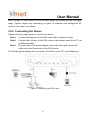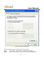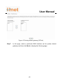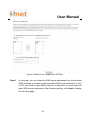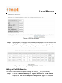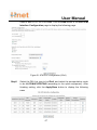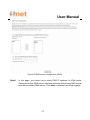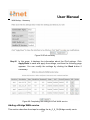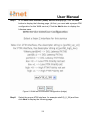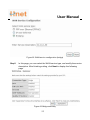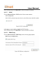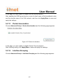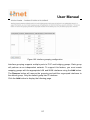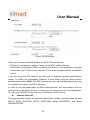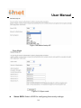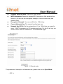
1
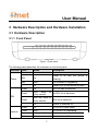
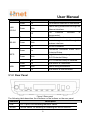
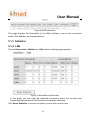
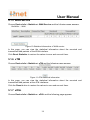
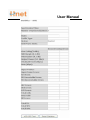
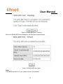
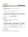
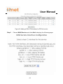
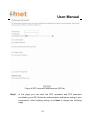
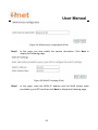
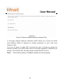
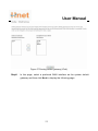
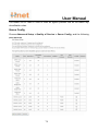
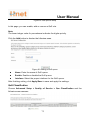
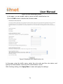
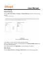
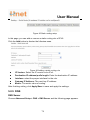
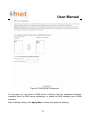
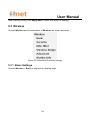
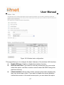
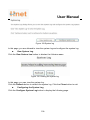
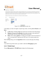
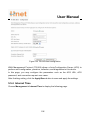
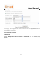
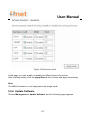
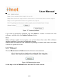
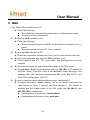
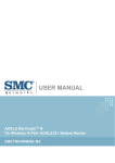
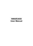
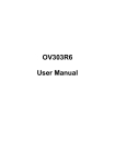
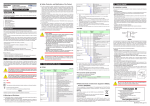
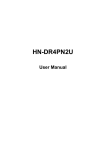
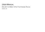
User Manual
HW-WD408
User Manual
Ver 1.0
User Manual
Contents
1
Safety Precautions ............................................................................................... 1
2
Overview ............................................................................................................... 2
3
2.1
Application ............................................................................................... 2
2.2
Features ................................................................................................... 2
2.3
Standards Compatibility and Compliance ............................................... 3
Hardware Description and Hardware Installation ................................................ 5
3.1
3.2
4
5
Hardware Description .............................................................................. 5
3.1.1
Front Panel ................................................................................... 5
3.1.2
Rear Panel .................................................................................... 6
Hardware Installation............................................................................... 7
3.2.1
Choosing the Best Location for Wireless Operation ................... 7
3.2.2
Connecting the Device ................................................................. 8
PC Network Configuration and Login .................................................................. 9
4.1
PC Network Configuration....................................................................... 9
4.2
Logging In to the DSL Router................................................................ 11
Web-Based Management................................................................................... 13
5.1
Device Information................................................................................. 13
5.1.1
Summary..................................................................................... 13
5.1.2
WAN............................................................................................ 14
5.1.3
Statistics ...................................................................................... 15
5.1.4
LAN ............................................................................................. 15
5.1.5
WAN Service............................................................................... 16
5.1.6
xTM ............................................................................................. 16
5.1.7
xDSL ........................................................................................... 16
5.1.8
Route........................................................................................... 20
5.1.9
ARP............................................................................................. 20
5.1.10
5.2
DHCP .................................................................................... 20
Advanced Setup .................................................................................... 21
5.2.1
Layer2 Interface.......................................................................... 22
5.2.2
WAN Service............................................................................... 26
5.2.3
LAN Configuration ...................................................................... 56
i
User Manual
5.3
5.4
5.5
6
5.2.4
NAT ............................................................................................. 62
5.2.5
Security ....................................................................................... 66
5.2.6
Parental Control.......................................................................... 71
5.2.7
Quality of Service ....................................................................... 72
5.2.8
Routing........................................................................................ 77
5.2.9
DNS............................................................................................. 78
5.2.10
DSL........................................................................................ 80
5.2.11
UPnP ..................................................................................... 81
5.2.12
DNS Proxy............................................................................. 81
5.2.13
Packet Acceleration .............................................................. 82
5.2.14
Interface Grouping ................................................................ 82
5.2.15
Multicast ................................................................................ 85
Wireless ................................................................................................. 86
5.3.1
Basic Settings ............................................................................. 86
5.3.2
Security ....................................................................................... 88
5.3.3
MAC Filter ................................................................................... 98
5.3.4
Wireless Bridge......................................................................... 100
5.3.5
Advanced Settings.................................................................... 101
5.3.6
Station Info................................................................................ 102
Diagnostics .......................................................................................... 102
Management ........................................................................................ 103
5.5.1
Settings ..................................................................................... 104
5.5.2
System Log ............................................................................... 105
5.5.3
TR-69 Client.............................................................................. 107
5.5.4
Internet Time............................................................................. 108
5.5.5
Access Control.......................................................................... 110
5.5.6
Update Software ....................................................................... 112
5.5.7
Reboot....................................................................................... 113
Q&A................................................................................................................... 114
ii
User Manual
1 Safety Precautions
Read the following information carefully before operating the device. Please follow
the following precaution items to protect the device from risks and damage caused
by fire and electric power:
=
Use volume labels to mark the type of power.
=
Use the power adapter that is packed within the device package.
=
Pay attention to the power load of the outlet or prolonged lines. An
overburden power outlet or damaged lines and plugs may cause electric
shock or fire accident. Check the power cords regularly. If you find any
damage, replace it at once.
=
Proper space left for heat dissipation is necessary to avoid any damage
caused by overheating to the device. The holes on the device are designed
for heat dissipation to ensure that the device works normally. Do not cover
these heat dissipation holes.
=
Do not put this device close to a place where a heat source exits or high
temperature occurs. Avoid the device from direct sunshine.
=
Do not put this device close to a place where is over damp or watery. Do not
spill any fluid on this device.
=
Do not connect this device to any PC or electronic product, unless our
customer engineer or your broadband provider instructs you to do this,
because any wrong connection may cause any power or fire risk.
=
Do not place this device on an unstable surface or support.
1
User Manual
2 Overview
The DSL Router is a highly ADSL2+ Integrated Access Device and can support
ADSL link with downstream up to 24 Mbps and upstream up to 1 Mbps. It is
designed to provide a simple and cost-effective ADSL Internet connection for a
private Ethernet or 802.11g/802.11b/802.11n wireless network. The Router
combines high-speed ADSL Internet connection, IP routing for the LAN and
wireless connectivity in one package. It is usually preferred to provide high access
performance applications for the individual users, the SOHOs, and the small
enterprises.
The Router is easy to install and use. The Modem connects to an Ethernet LAN or
computers via standard Ethernet ports. The ADSL connection is made using
ordinary telephone line with standard connectors. Multiple workstations can be
networked and connected to the Internet by a single Wide Area Network (WAN)
interface and single global IP address. The advanced security enhancements,
packet filtering and port redirection, can help protect your network from potentially
devastating intrusions by malicious agents from outside your network.
Network and Router management is done through the web-based management
interface that can be accessed through the local Ethernet using any web browser.
You may also enable remote management to enable configuration of the Router via
the WAN interface.
2.1 Application
=
Home gateway
=
SOHOs
=
Small enterprises
=
Higher data rate broadband sharing
=
PC file and application sharing
=
Network and online gaming
2.2 Features
2
User Manual
=
User-friendly GUI for web configuration
=
Several pre-configured popular games. Just enable the game and the port
settings are automatically configured.
=
Compatible with all standard Internet applications
=
Industry standard and interoperable DSL interface
=
Simple web-based status page displays a snapshot of system configuration,
and links to the configuration pages
=
Downloadable flash software updates
=
Support for up to 16 permanent virtual circuits (PVC)
=
Support for up to 8 PPPOE sessions
=
Support NAT
=
WLAN with high-speed data transfer rates of up to 150 Mbps, compatible
with IEEE 802.11b/g/n, 2.4GHz/5G compliant equipment
=
Optimized Linux 2.6 Operating System
=
IP routing and bridging
=
Asynchronous transfer mode (ATM) and digital subscriber line (DSL) support
=
Point-to-point protocol (PPP)
=
Network/port address translation (NAT/PAT)
=
Quality of service (QoS)
=
Wireless LAN security: WPA, 802.1x, RADIUS client
=
Virtual private network (VPN): IPSec
=
Universal plug-and-play
=
Management and control
-
Web-based management (WBM)
-
Command line interface (CLI)
-
TR-069 WAN management protocol
=
Remote update
=
System statistics and monitoring
=
DSL router is targeted at the following platforms: DSL modems, wireless
access points and bridge.
2.3 Standards Compatibility and Compliance
3
User Manual
=
Support application level gateway (ALG)
=
ITU G.992.1 (G.dmt)
=
ITU G.992.2 (G.lite)
=
ITU G.994.1 (G.hs)
=
ITU G.992.3 (ADSL2)
=
ITU G.992.5 (ADSL2+)
=
ANSI T1.413 Issue 2
=
IEEE 802.3
=
IEEE 802.3u
=
IEEE 802.11b
=
IEEE 802.11g
=
IEEE 802.11n
4
User Manual
3 Hardware Description and Hardware Installation
3.1 Hardware Description
3.1.1 Front Panel
Figure 1 Front panel
The following table describes the indicators on the front panel.
Indicator Color
Status
Description
Power
Green
On
Red
On
Red
Blink
The firmware is upgrading.
Off
Power is off or the device is down.
Green
Green
DSL
Green
Internet
Power is on.
Power is on and the device is
initiating.
On
Blink
DSL link has established.
twice
at
every second
Blink four times at
every second
No DSL link is detected.
DSL link is detected.
-
Off
Device is powered off.
Green
On
PPP/DHCP takes effect.
Green
Blink
PPP/DHCP is negotiating.
Green
Blink quickly
Data is being transmitted.
Red
On
Authentication fails.
5
User Manual
Indicator Color
LAN
Status
Description
Green
On
The Ethernet interface is connected.
Green
Blink
-
Off
Green
On
Green
Blink
-
Off
Green
On
Green
Blink
-
Off
Wi-Fi Protected Setup is disabled.
Green
On
USB device is connected.
Green
Blink
Data is being transmitted.
-
Off
USB device is disconnected.
Data is being transmitted through the
Ethernet interface.
1/2/3/4
WLAN
WPS
USB
The
Ethernet
interface
is
disconnected.
WLAN is enabled.
Data is being transmitted through the
wireless interface.
WLAN is disabled.
Connection succeeds under Wi-Fi
Protected Setup.
Negotiation is in progress under
Wi-Fi Protected Setup.
3.1.2 Rear Panel
Figure 2 Rear panel
The following table describes the interfaces or the buttons on the rear panel.
Interface
Description
Line
RJ-11 port, for connecting the ADSL cable.
WLAN
WLAN switch, for enabling or disabling the WALN function.
6
User Manual
Interface
Reset
Description
Press the button for at least 1 second and then release it. System
restores the factory default settings.
This button is used for enabling WPS PBC mode. If WPS is enabled,
WPS
press this button, and then the wireless router starts to accept the
negotiation of PBC mode.
LAN 4~1
RJ-45 port, for connecting the router to a PC or another network
device.
USB
USB port, for connecting the storage devices.
Power
Power interface, for connecting the power adapter.
Power switch
Warning:
Do not press the Reset button unless you want to clear the current settings. The
Reset button is in a small circular hole on the rear panel. If you want to restore the
default settings, please press the Reset button gently for 1 second with a fine needle
inserted into the hole and then release the button. The system reboots and returns to
the factory defaults.
The power specification is 12V, 1.25A. If the power adapter does not match the
specification, it may damage the device.
3.2 Hardware Installation
3.2.1 Choosing the Best Location for Wireless Operation
Many environmental factors may affect the effective wireless function of the DSL
Router. If this is the first time that you set up a wireless network device, read the
following information:
The access point can be placed on a shelf or desktop, ideally you should be able to
see the LED indicators in the front, as you may need to view them for troubleshooting.
Designed to go up to 100 meters indoors and up to 300 meters outdoors, wireless
LAN lets you access your network from anywhere you want. However, the numbers of
7
User Manual
walls, ceilings, or other objects that the wireless signals must pass through limit signal
range. Typical ranges vary depending on types of materials and background RF
noise in your home or business.
3.2.2 Connecting the Device
Please follow the steps below to connect the device.
Step1
Connect the Line port of the DSL router with a telephone cable.
Step2
Connect the LAN port of the DSL router to the network card of the PC via
an Ethernet cable.
Step3
Plug one end of the power adapter to the wall outlet and connect the
other end to the Power port of the DSL Router.
The followig figure displays the connection of the DSL router, PC, and telephones.
Figure 3 Connecting the DSL router
8
User Manual
4 PC Network Configuration and Login
4.1 PC Network Configuration
Each network interface on the PC should either be configured with a statically defined
IP address and DNS address, or be instructed to automatically obtain an IP address
using the network DHCP server. DSL router provides a DHCP server on its LAN and
it is recommended to configure your LAN to automatically obtain its IP address and
DNS server IP address.
The configuration principle is identical but should be carried out differently on each
operating system.
The following displays the TCP/IP Properties dialog box on Windows XP.
9
User Manual
Figure 4 IP and DNS configuration
TCP/IP configuration steps for Windows XP are as follows:
Step1
Choose Start > Control Panel > Network Connections.
Step2
Right-click the Ethernet connection icon and choose Properties.
10
User Manual
Step3
On the General tab, select the Internet Protocol (TCP/IP) component
Step4
The Internet Protocol (TCP/IP) Properties window appears.
Step5
Select the Obtain an IP address automatically radio button.
Step6
Select the Obtain DNS server address automatically radio button.
Step7
Click OK to save the settings.
and click Properties.
4.2 Logging In to the DSL Router
To log in to the DSL router, do as follows:
Step1
Open a Web browser on your computer.
Step2
Enter http://192.168.1.1 (the default IP address of the DSL router) in the
address bar. The login page appears.
Step3
Enter the user name and the password. The default username and
password of the super user are admin and admin. The username and
password of the common user are user and user. You need not enter the
username and the password again if you select the option Remember
my password. It is recommended to change these default values after
logging in to the DSL router for the first time.
Step4
Click OK to log in to the Web page. Otherwise, please click Cancel to exit
the login page.
11
User Manual
Figure 5 Login page
After logging in to the DSL router as a super user, you can query, configure, and
modify all the settings, and diagnose the system.
12
User Manual
5 Web-Based Management
This chapter describes how to use Web-based management of the DSL router, which
allows you to configure and control all of DSL router features and system parameters
in a user-friendly GUI.
5.1 Device Information
Choose Device Info, and the submenus of Device Info are shown as below:
Figure 6 Submenus of device info
5.1.1 Summary
Choose Device Info > Summary, and the following page appears.
13
User Manual
Figure 7 Summary page
This page displays the device information such as the board ID, software version, and
the information of your WAN connection such as the upstream rate and the LAN IPv4
address.
5.1.2 WAN
Choose Device Info > WAN and the following page appears.
14
User Manual
Figure 8 WAN information
This page displays the information of the WAN interface, such as the connection
status, IPv4 address, and connected time.
5.1.3 Statistics
5.1.4 LAN
Choose Device Info > Statistics > LAN and the following page appears.
Figure 9 LAN statistical information
In this page, you can view the statistical information about the recevied and
transmitted data packets of the Ethernet and wireless interfaces.
Click Reset Statistics to restore the values to zero and recount them.
15
User Manual
5.1.5 WAN Service
Choose Device Info > Statistics > WAN Service and the following page appears.
Figure 10 Statistical information of WAN service
In this page, you can view the statistical information about the recevied and
transmitted data packets of the WAN interface.
Click Reset Statistics to restore the values to zero and recount them.
5.1.6 xTM
Choose Device Info > Statistics > xTM and the following page appears.
Figure 11 xTM statistical information
In this page, you can view the statistical information about the recevied and
transmitted data packets at the xTM interfaces.
Click the Reset button to restore the values to zero and recount them.
5.1.7 xDSL
Choose Device Info > Statistics > xDSL and the following page appears.
16
User Manual
17
User Manual
Figure 12 xDSL statistical information
In this page, you can view the statistical information about the recevied and
transmitted data packets of the xDSL interfaces.
Click xDSL BER Test to test the xDSL Bit Error Rate.
Click Reset Statistics to restore the values to zero and recount them.
xDSL BER Test
Click xDSL BER Test to perform a bit error rate (BER) test on the DSL line. The test
page is as follows:
Figure 13 ADSL BER test
The Tested Time (sec) can be 1, 5, 10, 20, 60, 120, 180, 240, 300, or 360. Select a
time in the drop-down list and click Start. The following pages appear.
18
User Manual
Figure 14 ADSL BER test – running
When the ADSL BER test completes, the following page appears.
Figure 15 ADSL BER test result
Note:
If the BER reaches e-5, you cannot access the Internet.
19
User Manual
5.1.8 Route
Choose Device Info > Route and the following page appears.
Figure 16 Route table
In this page, you can view the route table information.
5.1.9 ARP
Choose Device Info > ARP and the following page appears.
Figure 17 ARP table
In this page, you can view the MAC address and IP address information of the device
connected to the router.
5.1.10
DHCP
Choose Device Info > DHCP and the following page appears.
20
User Manual
Figure 18 DHCP list
In this page, you can view the host name, the IP address assigned by the DHCP
server, the MAC address this is corresponding to the IP address, and the DHCP lease
time.
5.2 Advanced Setup
Choose Advanced Setup and the submenus of Advanced Setup are shown as
below:
21
User Manual
Figure 19 Submenus of advance setup
5.2.1 Layer2 Interface
ATM Interface
Choose Advanced Setup > Layer2 Interface > ATM Interface , and the following
page appears.
22
User Manual
Figure 20 DSL ATM interface configuration
In this page, you can add or remove the DSL ATM Interfaces.
Click the Add button to display the following page.
23
User Manual
Figure 21 ATM PVC configuration
In this page, you can set the VPI and VCI values, and select the DSL latency, link type
(EoA is for PPPoE, IPoE, and Bridge.), connection mode, encapsulation mode,
service category, and IP QoS scheduler algorithm.
=
VPI (Virtual Path Identifier): The virtual path between two points in an ATM
network, and its valid value is from 0 to 255.
=
VCI (Virtual Channel Identifier): The virtual channel between two points in
an ATM network, ranging from 32 to 65535 (1 to 31 are reserved for known
protocols).
=
Select DSL Latency: You may select Path0 and Path1.
=
Select DSL Link Type: You may select EoA (it is for PPPoE, IPoE, and
Bridge), PPPoA, or IPoA.
=
Select Connection Mode: You may select the Default Mode or the VLAN
MUX Mode.
=
Encapsulation Mode: You may select LLC/SNAP-BRIDGING or VC/MUX in
the drop-down list.
=
Service Category: you may select UBR Without PCR, UBR With PCR,
CBR, Non Realtime VBR or Realtime VBR in the drop-down lsit.
=
Select IP QoS Scheduler Algorithm: You may select Strict Priority and
Weighted Fair Queuing.
Note:
QoS cannot be set for CBR and Realtime VBR.
After finishing setting, click the Apply/Save button to make the settings take effect.
See the following figure:
Figure 22 Adding a DSL ATM interface
If you want to remove this Interface, please select the Remove check box that is
corresponding to the selected interface and then click the Remove button.
24
User Manual
ETH Interface
Choose Advanced Setup > Layer2 Interface > ETH Interface , and the following
page appears.
Figure 23 ETH WAN interface configuration
In this page, you can add or remove the ETH WAN interfaces.
Click the Add button to display the following page.
25
User Manual
Figure 24 Configuring a ETH WAN interface
In this page, select a ETH port and a proper connection mode, and then click the
Apply/Save button to make the settings take effect. See the following figure:
Figure 25 Adding a ETH WAN interface
If you want to remove this Interface, please select the Remove check box that is
corresponding to the selected interface and then click the Remove button.
5.2.2 WAN Service
Choose Advance Setup > WAN Service, and the following page appears.
Figure 26 WAN service configuration
In this page, you are allowed to add, remove, or edit a WAN service.
Adding a PPPoE WAN Service
This section describes the steps for adding the pppoe_0_0_35 (PPPoE mode)
service.
26
User Manual
Step1
In the Wide Area Network (WAN) Service Setup page, click the Add
button to display the following page. (At first, you must add a proper ATM
configuration for this WAN service.)
Figure 27 WAN service interface configuration (PPPoE)
Step2
In this page, you can select a ATM Interface for the WAN service. After
selecting the ATM interface, click Next to display the following page.
27
User Manual
Figure 28 WAN service configuration (PPPoE)
Step3
In this page, select the WAN service type to be PPP over Ethernet
(PPPoE). Click Next to display the following page.
28
User Manual
Figure 29 PPP username and password (PPPoE)
Step4
In this page, you can modify the PPP username, PPP password, PPPoE
service name and authentication method.
29
User Manual
=
PPP Username: The correct user name provided by your ISP.
=
PPP Password: The correct password provided by your ISP.
=
PPPoE Service Name: If your ISP provides it to you, please enter it. If not,
do not enter any information.
=
Authentication Method: The value can be AUTO, PAP, CHAP, or MSCHAP.
Usually, you can select AUTO.
=
Config KeepAlive: Whether to let the PPPoE dial-up keep alive.
=
Enable Fullcone NAT:. NAT is one where all requests from the same internal
IP address and port are mapped to the same external IP address and port.
Furthermore, any external host can send a packet to the internal host, by
sending a packet to the mapped external address.
=
Dial on demand (with idle timeout timer): If this function is enabled, you
need to enter the idle timeout time. Within the preset minutes, if the modem
does not detect the flow of the user continuously, the modem automatically
stops the PPPOE connection. Once it detects the flow (like access to a
webpage), the modem restarts the PPPoE dialup. If this function is disabled,
the modem performs PPPoE dial-up all the time. The PPPoE connnection
does not stop, unless the modem is powered off and DSLAM or uplink
equipment is abnormal.
=
PPP IP extension: If you want to configure DMZ Host, you should enable it
first.
=
Enable Firewall:If you want WAN connection to be safer,you should enable
firewall.
=
Use Static IPv4 Address: If this function is disabled, the modem obtains an
IP address assigned by an uplink equipment such as BAS, through PPPoE
dial-up. If this function is enabled, the modem uses this IP address as the
WAN IP address.
=
Enable PPP Debug Mode:Enable or disable this function.
=
Bridge PPPoE Frames Between WAN and Local Ports:Enable or disable
this function.
=
Enable IGMP Multicast Proxy:if you want PPPoE mode to support IPTV,
enable it.
Step5
After setting the parameters, click Next to display the following page.
30
User Manual
Figure 30 Routing-default gateway (PPPoE)
Step6
In this page, select a preferred WAN interface as the system default
gateway and then click Next to display the following page.
31
User Manual
Figure 31 DNS server configuration(PPPoE)
Step7
In this page, you may obtain the DNS server addresses from the selected
WAN interface or manually enter the static DNS server addresses. If only
a PVC with IPoA or static MER protocol is configured, you must manually
enter the static DNS server addresses. Click Next, and the following
page appears.
32
User Manual
Figure 32 PPPoE summary
Step8
In this page, it displays the information about the PPPoE settngs. Click
Apply/Save to save and apply the settings, and then the following page
appears. You can modify the settings by clicking the Back button if
necessary.
Figure 33 Completing the settings of PPPoE WAN service
Adding a MER (IPoE) WAN service
This section describes the steps for adding the ipoe_0_0_36 (MER mode) service.
Step1
In the Wide Area Network (WAN) Service Setup page, click the Add
button to display the following page. (At first, you must add a ATM
configuration for this WAN service.)
33
User Manual
Figure 34 WAN service interface configuration (IPoE)
Step2
Select an ATM Interface, for example, atm1/(0_0_36), and then click
Next to display the following page.
34
User Manual
Figure 35 WAN service configuration (IPoE)
Step3
In this page, select the WAN service type to be IP over Ethernet, and r
the service description. After finishing setting, click Next to display the
following page.
35
User Manual
Figure 36 WAN IP settings (IPoE)
Step4
In this page, you may themodify the WAN IP settings. You may select
obtain an IP address automatically or manually enter the IP address
provided by your ISP. Click Next and the following page appears.
Note:
If selecting Obtain an IP address automatically, DHCP will be enabled for PVC in
MER mode.
If selecting Use the following Static IP address, please enter the WAN IP address,
subnet mask and gateway IP address.
36
User Manual
Figure 37 Network address translation settings (IPoE)
Step5
In this page, you can set the network address translation settings,for
example, enabling NAT, enabling firewall, and.enabling IGMP multicast.
After finishing setting, click Next and the following page appears.
37
User Manual
Figure 38 Routing-default gateway (IPoE)
Step6
In this page, select a preferred WAN interface as the system default
gateway and then click Next to display the following page.
Figure 39 DNS server configuration (IPoE)
Step7
In this page, you may obtain the DNS server addresses from the selected
WAN interface or manually enter static DNS server addresses. If only a
PVC with IPoA or static MER protocol is configured, you must enter the
static DNS server addresses. After finishing setting, click Next to display
the following page.
38
User Manual
Figure 40 IPoE summary
Step8
In this page, it displays the information about the IPoE settngs.Click
Apply/Save to save and apply the settings, and then the following page
appears. You can modify the settings by clicking the Back button if
necessary.
Figure 41 Completing the settings of IPoA WAN service
Adding a PPPoA WAN service
This section describes the steps for adding the pppoa_0_0_37 (PPPoA mode)
service.
39
User Manual
Step1
Choose Advanced Setup > Layer2 Interface > ATM Interface to
dsipaly the DSL ATM Interface Configuration page. In this page, you
need to add a PVC for PPPoA mode. Click the Add button in the DSL
ATM Interface Configuration page to display the following page.
Figure 42 ATM PVC configuration (PPPoA)
Step2
Select the DSL link type to be PPPoA, and select the encapsulation
mode to be VC/MUX (according to the uplink equipment). After finishing
setting, click the Apply/Save button to apply the setings, and the
following page appears.
40
User Manual
Figure 43 Adding a DSL ATM interface for PPPoA service
Step3
Choose WAN Service and click Add to display the following page.
41
User Manual
Figure 44 WAN service interface configuration (PPPoA)
Step4
Select the proper interface for the WAN service, and then click Next to
display the following page.
Figure 45 WAN service configuration (PPPoA)
Step5
In this page, you may modify the service description. Click Next to
display the following page.
42
User Manual
Figure 46 PPP username and password (PPPoA)
Step6
In this page, you can enter the PPP username and PPP password
provided by your ISP. Select the authentication method according to your
requirement. After finishing setting, click Next to display the following
page.
43
User Manual
Figure 47 Routing-default gateway (PPPoA)
Step7
In this page, select a preferred WAN interface as the system default
gateway and then click Next to display the following page.
44
User Manual
Figure 48 DNS server configuration (PPPoA)
Step8
In this page, you can obtain the DNS server addresses from the selected
WAN interface or manually enter the static DNS server addresses. If only
a PVC with IPoA or static MER protocol is configured, you must enter the
static DNS server addresses. After finishing setting, click Next to display
the following page.
45
User Manual
Figure 49 PPPoA summary
Step9
In this page, it displays the information about the PPPoA settngs.Click
Apply/Save to apply the settings, and then the following page appears.
You can modify the settings by clicking the Back button if necessary.
Figure 50 Completing the settings of PPPoA WAN service
Adding an IPoA WAN service
This section describes the steps for adding the ipoa_0_0_38 (IPoA mode).
Step1
Choose Advanced Setup > Layer2 Interface > ATM Interface to
dsipaly the DSL ATM Interface Configuration page. In this page, you
46
User Manual
need to add a PVC for IPoA mode. Click the Add button in the DSL ATM
Interface Configuration page to display the following page.
Figure 51 ATM PVC configuration (IPoA)
Step2
Select the DSL link type to be IPoA, and select the encapsulation mode
to be LLC/SNAP-ROUTING (according to the uplink equipment). After
finishing setting, click the Apply/Save button to display the following
page.
47
User Manual
Figure 52 Adding a DSL ATM interface for IPoA service
Step3
Choose WAN Service and click Add to display the following page.
Figure 53 WAN service interface configuration (IPoA)
Step4
Select the proper interface for the WAN service ,and then click Next to
display the following page.
48
User Manual
Figure 54 WAN service configuration (IPoA)
Step5
In this page, you may modify the service description. Click Next to
display the following page.
Figure 55 WAN IP settings (IPoA)
Step6
In this page, enter the WAN IP address and the WAN subnet mask
provided by your ISP and then click Next to display the following page.
49
User Manual
Figure 56 Network address translation settings (IPoA)
In this page, Network Address Translation (NAT) allows you to share one Wide
Area Network (WAN) IP address for multiple computers on your Local Area
Network (LAN).
If you do not want to enable NAT, and wish the user of modem to access the
Internet normally, you need to add a route on the uplink equipment. Otherwise, the
access to the Internet fails. Normally, please enable the NAT function.
Step7
After finishing setting, click Next to display the following page.
50
User Manual
Figure 57 Routing-default gateway (IPoA)
Step8
In this page, select a preferred WAN interface as the system default
gateway and then click Next to display the following page.
51
User Manual
Figure 58 DNS server configuration (IPoA)
Step9
In this page, you should use a static DNS IP address for IPoA mode.
Select the proper DNS server interface and enter the primary DNS server
and the secondary DNS server. Click Next to display the following page.
52
User Manual
Figure 59 IPoA summary
Step10
In this page, it displays the information about the IPoA settngs. Click
Apply/Save to save and apply the settings, and then the following page
appears. You can modify the settings by clicking the Back button if
necessary.
Figure 60 Completing the settings of IPoA WAN service
Adding a Bridge WAN service
This section describes the steps for adding the br_0_0_39 (Bridge mode) service.
53
User Manual
Step1
In the Wide Area Network (WAN) Service Setup page, click the Add
button to display the following page. (At first, you must add a proper ATM
configuration for this WAN service.) Click the Add button to display the
following page.
Figure 61 WAN service interface configuration (bridge)
Step2
Select the proper ATM Interface, for example atm3/(0_0_39) and then
click Next to display the following page.
54
User Manual
Figure 62 WAN service configuration (bridge)
Step3
In this page, you can select the WAN service type, and modify the service
description. After finishing setting, click Next to display the following
page.
Figure 63 Bridge summary
55
User Manual
Step4
In this page, it displays the information about the bridge settngs. Click
Apply/Save to save and apply the settings, and then the following page
appears. You can modify the settings by clicking the Back button if
necessary.
Figure 64 Completing the settings of bridge WAN service
5.2.3 LAN Configuration
Choose Advanced Setup > LAN, and the following page appears.
56
User Manual
Figure 65 LAN setup
In this page, you can configure an IP address for the DSL router, enable IGMP
snooping, enable the LAN side firewall, enable or disable the DHCP server, edit the
57
User Manual
DHCP option, configure the DHCP advanced setup and set the binding between a
MAC address and an IP address.
Configuring the Private IP Address for the DSL Router
Figure 66 Configuring the IP address of the DSL router
In this page, you can modify the IP address of the device. The preset IP address is
192.168.1.1.
Enabling IGMP Snooping
IGMP snooping enables the router to forward multicast traffic intelligently, instead of
flooding all ports in the VLAN. With IGMP snooping, the router listens to IGMP
membership reports, queries and leave messages to identify the switch ports that are
members of multicast groups. Multicast traffic will only be forwarded to ports identified
as members of the specific multicast group or groups.
Figure 67 Configuring the IGMP snooping
In this page, you can enable the IGMP snooping and select the proper mode for
IGMP snooping.
Enabling the LAN Side Firewall
Firewall can prevent unexpected traffic on the Internet from your host in the LAN.
58
User Manual
Figure 68 Setting the LAN side firewall
In this page, you can enable or disable the LAN side firewall.
Configuring the DHCP Server
Figure 69 Setting the DHCP server
If you enable the DHCP sever, the clients will automatically acquire the IP address
from the DHCP server. If the DHCP server is disabled, you need to manually set the
start IP address, end IP address and the lease time for the clients in the LAN.
Editing the DHCP Option
Click the Edit DHCP Option button in the Local Area Network (LAN) Setup page to
display the DHCP Option Setup page.
59
User Manual
Figure 70 Configuring the DHCP options
In this page, you can add, edit or delete the DHCP options, and these options will be
sent to the DHCP client.
Editing the DHCP Option60
Click the Edit DHCP Option60 button in the Local Area Network (LAN) Setup page
to display the DHCP Option60 Setup page.
Figure 71 Configuring the DHCP60 options
In this page, you can add, edit or delete the DHCP60 options.
Configuring the DHCP Static IP Lease List
The lease list of static IP address can reserve the static IP addresses for the hosts
with the specific MAC addresses. When a host whose MAC address is in the lease
list of static IP address requests the DHCP server for an IP address, the DHCP server
assigns the reserved IP address to the host.
Figure 72 DHCP static lease list
Click the Add Entries button in the Local Area Network (LAN) Setup page to
display the DHCP Static IP Lease page.
60
User Manual
Figure 73 Adding an entry of DHCP static IP lease list
In this page, enter the MAC address of the LAN host and the static IP address that
is reserved for the host, and then click the Apply/Save button to apply the settings.
Configuring the Second IP Address and Subnet Mask for a LAN
Interface
In the Local Area Network (LAN) Setup page, you are allowed to set the second IP
address and the subnet mask for a LAN interface.
Figure 74 Setting the second IP address and subnet mask
After enabling Configure the second IP Address and Subnet Mask for LAN
interface, enter an IP address and a subnet mask for the LAN interface.
After finishing setting, click the Apply/Save button to apply the settings.
61
User Manual
5.2.4 NAT
Note:
The NAT information is not displayed in the bridge mode.
Virtual Servers
Firewall can prevent unexpected traffic on the Internet from your host on the LAN.
The virtual server can create a channel that can pass through the firewall. In that case,
the host on the Internet can communicate with a host on your LAN within certain port
range.
Choose Advanced Setup > NAT > Virtual Servers, and the following page appears.
Figure 75 Virtual server setup
In this page, you are allowed to add or remove a virtual server entry.
To add a virtual server, do as follows:
Click the Add button to display the following page.
62
User Manual
Figure 76 Adding an entry of virtual server
=
Use interface: Select an interface that you want to configure.
=
Select a Service: Select a proper service in the drop-down list.
=
Custom Server: Enter a new service name to establish a user service
type.
=
Server IP Address: Assign an IP address to virtual server.
=
External Port Start: When selecting a service, the port number will
automatically be displayed. You can modify it if necessary.
63
User Manual
=
External Port End: When selecting a service, the port number will
automatically be displayed. You can modify it if necessary.
=
Protocol: You may select TCP/UDP, TCP, or UDP in the drop-down list.
=
Internal Port Start: When selecting a service, the port number will
automatically be displayed. You can modify it if necessary.
=
Internal Port End: When selecting a service, the port number will
automatically be displayed. You can modify it if necessary.
After finishing setting, click Save/Apply to save and apply the settings.
Port Triggering
Some applications need some ports to be opened in the firewall for the remote
access. When an application initializes a TCP/UDP to connect to a remote user, port
triggering dynamically opens the open ports of the firewall.
Choose Advanced Settings > NAT > Port Triggering, and the following page
appears.
Figure 77 Port triggering setup
In this page, you may add or delete an entry of port triggering.
Click the Add button to display the following page.
64
User Manual
Figure 78 Adding an entry of port triggering
=
Use interface: Select an interface that you want to configure.
=
Select an application: Select a proper application in the drop-down list.
=
Custom application: Manually define an application.
=
Trigger port Start: The start port number that LAN uses to trigger the open
port.
=
Trigger port End: The end port number that LAN uses to trigger the open
port.
=
Trigger Protocol: Select the application protocol. You may select TCP/UDP,
TCP, or UDP.
=
Open Port Start: The start port number that is opened to WAN.
=
Open Port End: The end port number that is opened to WAN.
65
User Manual
=
Open Protocol: Select the proper protocol that is opened to WAN. You may
select TCP/UDP, TCP, or UDP.
After finishing setting, click Save/Apply to apply the settings.
Note:
You can use a single port number, several port numbers separated by commas, port
blocks consisting of two port numbers separated by a dash, or any combination of
these, for example 80, 90-140, 180.
DMZ Host
DMZ allows all the ports of a PC on your LAN to be exposed to the Internet. Set the IP
address of the PC to be DMZ host, so that the DMZ host will not be blocked by
firewall.
Choose Advanced Setup > NAT > DMZ host to display the following page.
Figure 79 DMZ host
In this page, enter the IP address of the DMZ host.
After finishing the settings, click the Apply/Save button to apply the settings.
If you want to clear the DMZ function of the host, please delete the IP address of the
host in the field of DMZ Host IP Address, and then click the Apply/Save button.
5.2.5 Security
By default, the firewall is enabled. The firewall is used to block the file transmission
between the Internet and your PC. It serves as a safety guard and permits only the
authorized files to be sent to the LAN.
Note:
66
User Manual
If the DSL router is configured to be bridge mode, IP filtering is disabled and the IP
filtering interface does not appear.
Outgoing IP Filtering Setup
When the outgoing IP filtering settings is enabled on the DSL router, the security
functions for the local network are enabled at the same time.
Choose Security > IP Filtering > Outgoing and the following page appears.
Figure 80 Outgoing IP filtering setup
By default, all outgoing IP traffic from LAN is allowed, but some IP traffic can be
blocked by setting filters.
In this page, you can add or remove the outgoing IP filtering rules.
Click the Add button to display the following page.
Figure 81 Adding an IP outgoing filtering rule
In this page, you can create a filter rule to identify the outgoing IP traffic by
specifying a new filter name and at least one condition.
67
User Manual
=
Filter Name: Set the filter name.
=
IP Version: Select the proper IP version in the drop-down list.
=
Protocol: Select a protocol that needs to be filtered.
=
Source IP address [/prefix length]: Set the range of local IP address.
=
Source Port (port or port: port): Set the local port.
=
Destination IP address [/prefix length]: Set the range of IP address of the
exterior network.
=
Destination Port (port or port: port): Set the port of the exterior network.
After finishing setting, click Apply/Save to save and activate the filtering rule.
Incoming IP Filtering Setup
The incoming IP filter is used to block and permit the IP packet transmisstion from the
internet.
Choose Security > IP Filtering > Incoming and the following page appears.
Figure 82 Incoming IP filtering setup
In this page, you can add or remove the incoming IP filtering rules.
Click the Add button to display the following page.
68
User Manual
Figure 83 Adding an IP incoming filtering rule
In this page, you can create a filter rule to identify the incoming IP traffic by
specifying a new filter name and at least one condition, and you must select at
least one WAN interface for the rule.
=
Filter Name: Set the filter name.
=
IP Version: Select the proper IP version in the drop-down list.
=
Protocol: Select a protocol that needs to be filtered.
=
Source IP address [/prefix length]: Set the range of local IP address.
=
Source Port (port or port: port): Set the local port.
=
Destination IP address [/prefix length]: Set the range of IP address of the
exterior network.
=
Destination Port (port or port: port): Set the port of the exterior network.
After finishing setting, click Apply/Save to save and activate the filtering rule.
69
User Manual
MAC Filtering Setup
In some cases, you may want to manage Layer2 MAC address to block or permit a
computer within the home network. When you enable MAC filter rules, the DSL router
serves as a firewall that works at layer 2.
Note:
MAC filtering is only effective on ATM PVCs configured in bridge mode. If the ATM
PVCs are configured in other routing modes (such as PPPoE mode), the MAC
Filtering Setup page does not be configured.
Choose Security > MAC Filtering and the following page appears.
Figure 84 MAC filtering setup
In this page, you can add or remove the MAC filtering rule. You may change the MAC
filtering policy from FORWARDED to BLOCKED by clicking the Change Policy
button.
Click the Add button to display the following page.
70
User Manual
Figure 85 Adding a MAC filter
=
Protocol Type: Select the proper protocol type.
=
Destination MAC Address: Enter the destination MAC address.
=
Source MAC Address: Enter the source MAC address.
=
Frame Direction: The direction of transmission frame.
=
WAN Interface (Configured in bridge mode only): Select the proper
WAN interface in the drop-down list.
After finishing setting, click Apply/Save to save and apply the filtering rule.
5.2.6 Parental Control
Time Restriction
Choose Advanced Setup > Parental Control > Time Restriction, and the following
page appears.
Figure 86 Time restriction setup
Click the Add button to display the following page.
71
User Manual
Figure 87 Adding a time restriction rule
This page is used to control the time restriction to a special LAN device that connects
to the DSL router. In this page, se the user name and configure the time settings.
After finishing setting, click Apply/Save to save and apply the settings.
5.2.7 Quality of Service
Enabling QoS
Choose Advance Setup > Quality of Service and the following page appears.
72
User Manual
Figure 88 QoS queue management configuration
Select Enable QoS to enable QoS and configure the default DSCP mark.
Figure 89 Enabling QoS
In this page, enable the QoS function and select the default DSCP mark.
After finishing setting, click Apply/Save to save and apply the settings.
Note:
If the Enable Qos checkbox is not selected, all QoS will be disabled for all interfaces.
73
User Manual
The default DSCP mark is used to mark all egress packets that do not match any
classification rules.
Queue Config
Choose Advanced Setup > Quality of Service > Queue Config, and the following
page appears.
74
User Manual
Figure 90 QoS queue setup
In this page, you can enable, add or remove a QoS rule.
Note:
The lower integer value for precedence indicates the higher priority.
Click the Add button to display the following page.
Figure 91 Adding a QoS queue
=
Name: Enter the name of QoS queue.
=
Enable: Enable or disable the QoS queue.
=
Interface: Select the proper interface for the QoS queue.
After finishing setting, click Apply/Save to save and apply the settings.
QoS Classification
Choose Advanced Setup > Quality of Service > Qos Classification and the
following page appears.
75
User Manual
Figure 92 QoS classification setup
In this page, you can enable, add or remove a QoS classification rule.
Click the Add button to display the following page.
Figure 93 Adding a QoS classification rule
In this page, enter the traffic name, select the rule order and the rule status, and
specify the classification criteria and the classification results.
After finishing setting, click Apply/Save to save and apply the settings.
76
User Manual
5.2.8 Routing
Default Gateway
Choose Advanced Setup > Routing > Default Gateway, and the following page
appears.
Figure 94 Default gateway setup
In this page, you can modify the default gateway settings.
Select a proper WAN interface in the drop-down list of Selected WAN Interface as
the system default gateway.
After finishing setting, click Apply/Save to save and apply the settings.
Static Route
Choose Advanced Setup > Routing > Static Route and the following page appears.
77
User Manual
Figure 95 Static routing setup
In this page, you can add or remove a static routing rule of IPV4.
Click the Add button to display the following page.
Figure 96 Adding a static routing rule
=
IP Version: Select the IP version to be IPv4.
=
Destination IP address/prefix length: Enter the destination IP address.
=
Interface: select the proper interface for the rule.
=
Gateway IP Address: The next-hop IP address.
=
Metric: The metric value of routing.
After finishing setting, click Apply/Save to save and apply the settings.
5.2.9 DNS
DNS Server
Choose Advanced Setup > DNS > DNS Server and the following page appears.
78
User Manual
Figure 97 DNS server configuration
In this page, you can select a DNS server interface from the available interfaces,
manually enter the DNS server addresses, or obtain the DNS address from a WAN
interface.
After finishing setting, click Apply/Save to save and apply the settings.
79
User Manual
5.2.10
DSL
Choose Advanced Setup > DSL and the following page appears.
Figure 98 DSL settings
In this page, you can set the DSL settings. Usually, you do not need to modify the
factory default settings.
80
User Manual
After finishing setting, click Apply/Save to save and apply the settings.
5.2.11
UPnP
Choose Advanced Setup > UPnP and the following page appears.
Figure 99 UPnP configuration
In this page, you can enable or disable the UPnP function.
After finishing setting, click Apply/Save to save and apply the settings.
5.2.12
DNS Proxy
Choose Advanced Setup > DNS Proxy and the following page appears.
Figure 100 DNS proxy configuration
81
User Manual
In this page, you can enable or disable the DNS proxy function.
After enabling the DNS proxy function, enter the host name of the broadband router
and the domain name of the LAN network, and then click Apply/Save to save and
apply the settings.
5.2.13
Packet Acceleration
Choose Advanced Setup > Packet Acceleration and the following page appears.
Figure 101 Packet Acceleration
In this page, you can enable or disable Packet Flow Accelerator.
After finishing setting, click Apply/Save to save and apply the settings.
5.2.14
Interface Grouping
Choose Advanced Setup > Interface Grouping and the following page appears.
82
User Manual
Figure 102 Interface grouping configuration
Interface grouping supports multiple ports to PVC and bridging groups. Each group
will perform as an independent network. To support this feature, you must create
mapping groups with the appropriate LAN and WAN interfaces using the Add button.
The Remove button will remove the grouping and add the ungrouped interfaces to
the default group. Only the default group has IP interface.
Click the Add button to display the following page.
83
User Manual
Figure 103 Adding a new interface group
84
User Manual
In this page, please follow the on-screen configuration steps to configure the
parameters of the interface grouping.
After finishing setting, click Apply/Save to save and apply the settings.
5.2.15
Multicast
Choose Advanced Setup > Multicast and the following page appears.
Figure 104 Multicast configuration
In this page, you can configure the multicast parameters of the IPv4.
85
User Manual
After finishing setting, click Apply/Save to save and apply the settings.
5.3 Wireless
Choose Wireless and the submenus of Wireless are shown as below:
Figure 105 Submenus of wireless settings
5.3.1 Basic Settings
Choose Wireless > Basic to display the following page.
86
User Manual
Figure 106 Wireless basic configuration
This page allows you to configure the basic features of the wireless LAN interface.
=
Enable Wireless: Enable or disable the wireless function.
=
Hide Access Point: if you want to hide any access point for your router,
select this option, and then a station cannot obtain the SSID through the
passive scanning.
=
Clients Isolation: When many clients connect to the same access point,
they can access each other. If you want to disable the access between the
clients that connect to the same access point, you can select this option.
87
User Manual
=
Disable WMM Advertise: After enabling this option, the transmission
performance multimedia of the voice and video data can be improved.
=
Enable Wireless Multicast Forwarding (WMF): After enabling this option,
the transmission quality of video service such as IPTV can be improved.
=
SSID: For the security reason, you should change the default SSID to a
unique name.
=
BSSID: Display the MAC address of the wireless interface.
=
Country: The name of the country with which your gateway is configured.
This parameter further specifies your wireless connection. For example, The
channel will adjust according to nations to adapt to each nation's frequency
provision.
=
Max Clients: Specify the maximum wireless client stations to be enabled to
link with AP. Once the clients exceed the max vlaue, all other clients are
refused. The value of maximum clients is 16.
=
Wireless - Guest/Virtual Access Points: If you want to make Guest/Virtual
network function be available, you have to check those boxes in the table
below. In the current software version, three virtual access points can be
configured.
After finishing setting, click Apply/Save to save the basic wireless settings and make
the settings take effect.
5.3.2 Security
Choose Wireless > Security to display the following page.
88
User Manual
Figure 107 Wireless security configuration
This page allows you to configure the security features of the wireless LAN interface.
In this page, you can configure the network security settings by the Wi-Fi Protected
Setup (WPS) method or setting the network authentication mode.
=
WPS Setup
89
User Manual
Figure 108 WPS setup
There are 2 primary methods used in the Wi-Fi Protected Setup:
- PIN entry, a mandatory method of setup for all WPS certified devices.
- Push button configuration (PBC), an actual push button on the hardware or through
a simulated push button in the software. (This is an optional method on wireless
client).
If you are using the PIN method, you will need a Registrar (access point/wireless
router) to initiate the registration between a new device and an active access
point/wireless router. (Note: The PBC method may also need a Registrar when used
in a special case where the PIN is all zeros)
In order to use the push-button for WPS authentication, you must ensure that the
network card support the function. if it supports, you need not to do any configuration.
You can press the WPS button directly to enable the WPS function.
=
Manual Setup AP
This page provides 9 types of network authentication modes, including Open, Shared,
802.1X, WPA, WPA-PSK, WPA2, WPA2-PSK, Mixed WPA2/WPA, and Mixed
WPA2/WPA-PSK.
90
User Manual
Figure 109 Manual setup AP
- Open Mode
Figure 110 Open mode
=
Select SSID: Select a SSID for configuring the security settings.
91
User Manual
=
Network Authentication: Select the Open mode.
=
WEP Encryption: Enable or disable WEP encryption. After enabling this
function, you can set the encryption strength, current network key, and
network keys.
=
Encryption Strength: You can set 64-bit or 128-bit key.
=
Current Network Key: The current key that you use.
=
Network Key1/2/3/4: Set the network key. If it is 128-bit key, you need to
enter 13 ASCII characters or 26 hexadecimal digits. For the 64-bit key, you
need to enter 5 ASCII characters or 10 hexadecimal digits.
- Shared Mode
Figure 111 Shared mode
The parameters’ description of shared mode, please refer to the Open Mode.
- 802.1x
92
User Manual
Figure 112 802.1x mode
=
Select SSID: Select a SSID for configuring the security settings.
=
Network Authentication: Select the 802.1X in the drop-down list.
=
RADIUS Server IP Address: Enter the IP address of the RADIUS server.
RADIUS server is used to authenticate the hosts on the wireless network.
=
RADIUS Port: The port number that the RADIUS server uses. The default
port number is 1812. You may change it according to the server setting.
=
RADIUS Key: Set the RADIUS key for accessing the RADIUS server.
=
WEP Encryption: You can only select Enabled.
=
Encryption Strength: You can set 64-bit or 128-bit key.
=
Current Network Key: The current key that you use.
=
Network Key1/2/3/4: Set the network key. If it is 128-bit key, you need to
enter 13 ASCII characters or 26 hexadecimal digits. For the 64-bit key, you
need to enter 5 ASCII characters or 10 hexadecimal digits.
93
User Manual
- WPA Mode
Figure 113 WPA mode
=
Select SSID: Select a SSID for configuring the security settings.
=
Network Authentication: Select the WPA-PSK mode.
=
WPA Group Rekey Interval: Setting the interval for renewing key.
=
RADIUS Server IP Address: Enter the IP address of the RADIUS server.
RADIUS server is used to authenticate the hosts on the wireless network.
=
RADIUS Port: The port number that the RADIUS server uses. The default
port number is 1812. You may change it according to the server setting.
=
RADIUS Key: Set the RADIUS key for accessing the RADIUS server.
=
WPA/WAPI Encryption: You may select AES, or TKIP+AES.
- WPA-PSK Mode
94
User Manual
Figure 114 WPA-PSK mode
=
Select SSID: Select a SSID for configuring the security settings.
=
Network Authentication: Select the WPA-PSK mode.
=
WPA/WAPI passphrase: The key for WPA encryption. Click the Click here
to display button to display the current key. The default key is 87654321.
=
WPA Group Rekey Interval: Setting the interval for renewing key.
=
WPA/WAPI Encryption: You may select AES, or TKIP+AES.
- WPA2 Mode
95
User Manual
Figure 115 WPA2 Mode
=
Select SSID: Select a SSID for configuring the security settings.
=
Network Authentication: Select the WPA2 mode.
=
WPA2 Preauthentication: Enable or disable pre-authentication.
=
Network Re-auth Interval: Set the network re-auth interval.
=
WPA Group Rekey Interval: Setting the interval for renewing key.
=
RADIUS Server IP Address: Enter the IP address of the RADIUS server.
RADIUS server is used to authenticate the hosts on the wireless network.
=
RADIUS Port: The port number that the RADIUS server uses. The default
port number is 1812. You may change it according to the server setting.
=
RADIUS Key: Set the RADIUS key for accessing the RADIUS server.
=
WPA/WAPI Encryption: You may select AES, or TKIP+AES.
- WPA2-PSK
96
User Manual
Figure 116 WPA2-PSK mode
The parameters’ description of WPA2-PSK mode, please refer to the WPA-PSK
mode.
- Mixed WPA2/WPA
97
User Manual
Figure 117 Mixed WPA2/WPA
The parameters’ description of Mixed WPA2/WPA mode, please refer to the WPA2
mode.
- Mixed WPA2/WPA-PSK
Figure 118 Mixed WPA2/WPA-PSK mode
The parameters’ description of Mixed WPA2/WPA-PSK mode, please refer to the
WPA-PSK mode.
5.3.3 MAC Filter
Choose Wireless > MAC Filter to display the following page.
98
User Manual
Figure 119 MAC filter configuration
This page is used to allow or reject the wireless clients to access the wireless network
of the wireless router.
In this page, you can add or remove the MAC filters.
The MAC restrict modes include Disabled, Allow, and Deny.
=
Disabled: Disable the wireless MAC address filtering function.
=
Allow: Allow the wireless clients with the MAC addresses in the MAC
Address list to access the wireless network of the wireless router.
=
Deny: Reject the wireless clients with the MAC addresses in the MAC
Address list to access the wireless network of the wireless router.
Click the Add button to display the following page.
99
User Manual
Figure 120 Adding a MAC filter
In this page, enter the MAC address of the wireless client, and then click the
Apply/Save button to add the MAC address to the MAC address list.
5.3.4 Wireless Bridge
Choose Wireless > Wireless Bridge to display the following page.
Figure 121 Wireless bridge configuration
This page allows you to configure the wireless bridge features of the wireless LAN
interface.
=
AP mode: you may select Access Point or Wireless Bridge.
=
Bridge Restrict: Enable or disable the bridge restrict function.
=
Remote Bridges MAC Address: Enter the remote bridge MAC address.
After finishing setting, click the Apply/Save button to save and apply the settings.
100
User Manual
5.3.5 Advanced Settings
Choose Wireless > Advanced to display the following page.
Figure 122 Wireless advanced settings
This page allows you to configure the advanced features of the wireless LAN
interface. Usually, you do not need to change the settings in this page.
101
User Manual
Note:
The advanced wireless setting is only for the advanced user. For the common user,
do not change any settings in this page.
5.3.6 Station Info
Choose Wireless > Station Info to display the following page.
Figure 123 Station information
This page shows the authenticated wireless stations and their status.
5.4 Diagnostics
Choose Diagnostics, and the following page appears.
102
User Manual
Figure 124 Diagnostics configuration
This page is used to test the connection to your local network, the connection to your
DSL service provider, and the connection to your Internet service provider.
You may diagnose the connection by clicking the Test button or click the Test With
OAMF4 button.
5.5 Management
Choose Management and the submenus of Management are shown as below:
103
User Manual
Figure 125 Submenus of management
5.5.1 Settings
Backup
Choose Management > Settings > Backup to display the following page.
Figure 126 Backup settings
In this page, click the Backup Settings button to save your router’s settings to your
local PC.
Update
Choose Management > Settings > Update, and the following page appears.
104
User Manual
Figure 127 Update settings
In this page, click the Browse… button to select the correct new settings file, and
then click the Update Settings button to update the router’s settings.
Restore Default
Choose Management > Settings > Restore Default to display the following page.
Figure 128 Restoring the default settings
In this page, click the Restore default settings button, and then system returns to
the default settings.
5.5.2 System Log
Choose Management > System Log to display the following page.
105
User Manual
Figure 129 System log
In this page, you are allowed to view the system log and configure the system log.
=
View System Log
Click the View System Log button to display the following page.
Figure 130 Viewing the system log
In this page, you can view the system log.
Click the Refresh button to refresh the system log. Click the Close button to exit.
=
Configuring the System Log
Click the Configure System Log button to display the following page.
106
User Manual
Figure 131 Configuring the system log
In this page, you can set 3 types of system log modes, including Local, Remote, and
Both.
=
=
Local: When selecting Local, the events are recorded in the local memory.
Remote: When selecting Remote, the events are sent to the specified IP
address and UDP port of the remote system log server.
=
Both: When selecting Both, the events are recorded in the local memory or
sent to the specified IP address and UDP port of the remote system log
server.
After finishing setting, click the Apply/Save button to save and apply the settings.
Note:
If you want to log all the events, you need to select the Debugging log level.
5.5.3 TR-69 Client
Choose Management > TR-069Client to display the following page.
107
User Manual
Figure 132 TR-069 client configuration
WAN Management Protocol (TR-069) allows a Auto-Configuration Server (ACS) to
perform auto-configuration, provision, collection, and diagnostics to this device.
In this page, you may configure the parameters such as the ACS URL, ACS
password, and connection request user name.
After finishing setting, click the Apply/Save button to save and apply the settings.
5.5.4 Internet Time
Choose Management > Internet Time to display the following page.
108
User Manual
Figure 133 Time settings
In this page, you may configure the router to synchronize its time with the Internet
time servers.
After enabling Automatically synchronize with Internet time servers, the following
page appears.
109
User Manual
Figure 134 Setting the time server
In this page, set the proper time servers, and then click the Apply/Save button to
save and apply the settings.
5.5.5 Access Control
Passwords
Choose Management > Access Control > Passwords, and the following page
appears.
110
User Manual
Figure 135 Modifying the password
In the page, you can modify the passwords of different users.
After finishing setting, click the Apply/Save button to save and apply the settings.
Services
Choose Management > Access Control > Services Control and the following page
appears.
111
User Manual
Figure 136 Services control
In this page, you can enable or disable the different types of services.
After finishing setting, click the Apply/Save button to save and apply the settings.
Note:
The WAN information is not displayed in the bridge mode.
5.5.6 Update Software
Choose Management > Update Software, and the following page appears.
112
User Manual
Figure 137 Updating software
If you want to upload the software, click the Browse… button to choose the new
software, and then click the Update Software button.
Note:
When software update is in progress, do not shut down the router. After software
update completes, the router automatically reboots.
Please make sure that the new software for updating is correct, and do not use other
software to update the router.
5.5.7 Reboot
Choose Management > Reboot and the following page appears.
Figure 138 Rebooting the router
In this page, click the Reboot button, and then the router reboots.
113
User Manual
6 Q&A
(1) Q: Why all the indicators are off?
A: Check the following:
(2)
=
The connection between the power adaptor and the power socket.
=
The status of the power switch.
Q: Why the LAN indicator is off?
A: Check the following:
=
The connection between the ADSL router and your computer, hub, or
switch.
=
(3)
The running status of your PC, hub, or switch.
Q: Why the DSL indicator is off?
A: Check the connection between the “Line” port of router and the wall jack.
(4)
Q: Why Internet access fails while the DSL indicator is on?
A: Check whether the VPI, VCI, user name, and password are correctly
entered.
(5)
Q: Why I fail to access the web configuration page of the DSL router?
A: Choose Start > Run from the desktop, and ping 192.168.1.1 (IP address of
the DSL router). If the DSL router is not reachable, check the type of the
network cable, the connection between the DSL router and the PC, and
the TCP/IP configuration of the PC.
(6)
Q: How to load the default settings after incorrect configuration?
A: To restore the factory default settings, turn on the device, and press the
reset button for about 1 second, and then release it. The default IP
address and the subnet mask of the DSL router are 192.168.1.1 and
255.255.255.0, respectively.
=
User/password of super user: admin/admin
=
User/password of common user: user/user
114