1
Interfacing to a SWTPC 6800 and non-300 Baud Terminal System
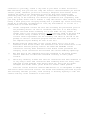
Since the AC-30 Audio Cassette Interface must be operated RS-232 serial at
300 baud, it cannot be implemented serially between the computer's control
interface and the terminal system on non-300 baud or non-RS-232 terminal systems.
The only option the user has in these cases is to operate the AC-30 Cassette
Interface thru an optional serial type interface connected to one of the unused I/0
slots on the computer system. The big disadvantage here is that the MIKBUG resident
tape load and dump routines are only functional on the I/0 slot #1, the MP-C
Control Interface position. Locating the AC-30 Cassette Interface at any other I/0
position means that all tape load and dump routines will have to be keyed in
manually by the user before the AC-30 Audio Cassette Interface can actually be used
to load programs. The other problem is that we no longer have any way of deriving
motor control for the cassette unit since motor control commands sent out thru the
MP-C Control Interface on I/0 card slot #1 are of no use to us. On top of that the
standard MP-S serial interface option does not have enough control lines available
to provide READER ON, READER OFF, RECORD ON and RECORD OFF logic control for the
attached AC-30 Cassette Interface. For these reasons it is our recommendation that
the AC-30 be interfaced to the computer system thru a separate MP-C Control
Interface configured for 300 baud located at some unused I/0 card position on the
interface buss. This means there will be a larger overhead in software for the user
but the extra unused parallel lines on the parallel PIA integrated circuit may be
used for AC-30 READER ON, READER OFF, RECORD ON, and RECORD OFF control functions.
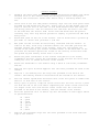
Our cassette version of the Editor/Assembler software already has I/0 routines
contained within to drive an MP-C Control Interface located at any I/0 card
position on the SWTPC 6$00 Computer System. READER ON, READER OFF, RECORD ON and
RECORD OFF control commands may be taken off unused pins on the PIA parallel
interface chip. The lines have been assigned on the control interface when using
the Editor/Assembler software package. It is suggested that you use the same
assignments to maintain consistency.
To actually use these logic/control lines within your own programming you
will have to write routines within your own cassette I/0 software package to put a
TTL compatible 1 to 1000 microsecond negative going strobe pulse on the respective
PIA pin to generate the desired command. A connector is attached from these MP-C
PIA pins to the control lines on the AC-30 Cassette Interface and is installed as
follows.
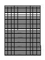
Make the connections from the indicated pins of ICI on the MP-C Control
Interface board to the specified pins of a twelve pin male connector shell, Be sure
to make the wires long enough to reach your AC-30 Cassette Interface where the
connector will be plugged:
FROM
MP-C IC1 pin 7
MP-C IC1 pin 4
MP-C IC1 pin 6
MP-C IC1 pin 5
Terminal's 16X clock OUT
Terminal's 16X clock IN
MP-C ground
12
12
12
12
12
12
12
pin
pin
pin
pin
pin
pin
pin
male
male
male
male
male
male
male
TO
shell
shell
shell
shell
shell
shell
shell
female
female
female
female
female
female
female
pin
pin
pin
pin
pin
pin
pin
#1
#2
#3
#4
#5
#6
#12
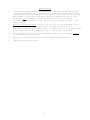
The mating connector on the AC-30 Cassette Interface should be installed just
as is shown in the interconnection drawing for the SWTPC 6800 and CT=1024 Terminal
System. Other connections are made as shown in the appropriate block diagram. All
data connections made to the AC-30 should be thru the connector provided for the
computer. Since there will be no terminal connected directly to the AC-30 there is
of course no LOCAL mode of operation for the cassette system.
18