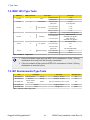
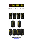
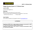
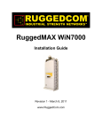
1
RuggedSwitch™
RS900 Family
Hardware Installation Guide
Revision 110 - August 26, 2011
www.RuggedCom.com
RuggedSwitch™ RS900 Family
RuggedSwitch™ RS900 Family: Hardware Installation Guide
Copyright © 2011 RuggedCom Inc.
All Rights Reserved
Dissemination or reproduction of this document, or evaluation and communication of its contents, is not authorized except where expressly
permitted. Violations are liable for damages. All rights are reserved, particularly for the purposes of patent application or trademark registration.
This document contains proprietary information, which is protected by copyright. All rights are reserved. No part of this document may be
photocopied, reproduced or translated to another language without the prior written consent of RuggedCom Inc.
Disclaimer Of Liability
We have checked the contents of this manual against the hardware and software described. However, deviations from the description cannot
be completely ruled out.
RuggedCom shall not be liable for any errors or omissions contained herein or for consequential damages in connection with the furnishing,
performance, or use of this material.
The information given in this document is reviewed regularly and any necessary corrections will be included in subsequent editions. We appreciate
any suggested improvements. We reserve the right to make technical improvements without notice.
Registered Trademarks
ROX™, RuggedBackbone™, RuggedRated™ and eRSTP™ are trademarks of RuggedCom Inc. ROS®, RuggedRouter® and RuggedSwitch®
are registered trademarks of RuggedCom Inc. Other designations in this manual might be trademarks whose use by third parties for their own
purposes would infringe the rights of the owner.
Linux® is the registered trademark of Linus Torvalds in the U.S. and other countries.
The registered trademark Linux® is used pursuant to a sublicense from LMI, the exclusive licensee of Linus Torvalds, owner of the mark on
a world-wide basis.
Warranty
Five (5) years from date of purchase, return to factory. For warranty details, visit www.RuggedCom.com or contact your customer service
representative.
Contacting RuggedCom
Corporate Headquarters
US Headquarters
Europe Headquarters
RuggedCom Inc.
300 Applewood Crescent,
Concord, Ontario
Canada, L4K 5C7
Tel: +1 905 856 5288
Fax: +1 905 856 1995
Toll-free: 1 888 264 0006
RuggedCom
1930 Harrison Street, Suite 209
Hollywood, Florida
USA, 33020
Tel: +1 954 922 7938 ext.103
Fax: +1 954 922 7984
Toll-free: 1 888 264 0006
RuggedCom
Unit 41, Aztec Centre,
Aztec West, Almondsbury, Bristol
United Kingdom BS32 4TD
Tel: +44 1454 203 404
Fax: +44 1454 203 403
Email: [email protected]
Technical Support
Toll Free (North America): 1 866 922 7975
International: +1 905 856 5288
Email: [email protected]
Web: www.RuggedCom.com
RuggedSwitch™ RS900 Family
Table of Contents
FCC Statement And Cautions ................................................................................................... 7
1. Product Overview ................................................................................................................... 8
1.1. Functional Overview .................................................................................................... 8
1.2. RuggedSwitch® ........................................................................................................... 9
1.2.1. RS900 ............................................................................................................... 9
1.3. RuggedWireless™ Family of Products ..................................................................... 10
1.3.1. RS900W ......................................................................................................... 10
1.3.2. RS910W ......................................................................................................... 11
1.3.3. RS920W ......................................................................................................... 12
1.3.4. RS930W ......................................................................................................... 13
1.4. RuggedVDSL™ Family of Products .......................................................................... 14
1.4.1. RS900L ........................................................................................................... 14
1.4.2. RS910L ........................................................................................................... 15
1.4.3. RS920L ........................................................................................................... 16
1.4.4. RS930L ........................................................................................................... 17
1.5. RuggedServer™ ........................................................................................................ 18
1.5.1. RS910 ............................................................................................................. 18
1.6. Front Panel Description ............................................................................................ 19
1.7. Bottom Panel Description ......................................................................................... 19
2. Installation ............................................................................................................................ 20
2.1. DIN Rail Mounting ..................................................................................................... 20
2.2. Power Supply Wiring and Grounding ........................................................................ 21
2.2.1. AC Power Supply Wiring and Grounding ....................................................... 21
2.2.2. DC Power Supply Wiring and Grounding ....................................................... 22
2.2.3. Failsafe Output Wiring .................................................................................... 22
2.2.4. Dielectric Strength Testing ............................................................................. 23
2.3. Console Port Wiring .................................................................................................. 23
3. Ethernet Ports ...................................................................................................................... 24
3.1. Ethernet over VDSL Port .......................................................................................... 24
3.1.1. Overview ......................................................................................................... 24
3.1.2. Wiring ............................................................................................................. 24
3.1.3. RJ11 Port ....................................................................................................... 25
3.1.4. Configuration & Setup .................................................................................... 25
3.1.5. Performance ................................................................................................... 25
3.2. Copper Ethernet Port ................................................................................................ 27
3.3. Fiber Optic Ethernet Port .......................................................................................... 28
3.4. Wireless Ethernet Port .............................................................................................. 28
4. Serial Ports .......................................................................................................................... 29
4.1. DB9 Serial Port ......................................................................................................... 29
4.2. RJ45 Serial Port ........................................................................................................ 30
4.3. Fiber Serial Port ........................................................................................................ 31
4.4. RS485 Wiring ........................................................................................................... 32
5. Transient Protection ............................................................................................................ 33
6. Technical Specifications ....................................................................................................... 34
6.1. Operating Environment ............................................................................................. 34
6.2. Power Supply Specifications ..................................................................................... 34
RuggedCom® RuggedSwitch™
3
RS900 Family Installation Guide Rev 110
RuggedSwitch™ RS900 Family
6.3. Failsafe Relay Specifications ....................................................................................
6.4. Ethernet Ports Specifications ....................................................................................
6.4.1. RJ11 Ethernet over VDSL Port Specifications ...............................................
6.4.2. RJ45 Ethernet Port Specifications ..................................................................
6.4.3. Fiber Optic Ethernet Port Specifications ........................................................
6.4.4. Communication Standards .............................................................................
6.5. Wireless Ethernet Port Specification ........................................................................
6.5.1. Supported Wireless Standards .......................................................................
6.5.2. Radio Characteristics .....................................................................................
6.5.3. Channel Allocations for IEEE 802.11b/g .......................................................
6.6. Serial Ports Specifications ........................................................................................
6.6.1. DB9 & RJ45 Serial Port Specifications ..........................................................
6.6.2. Fiber Serial Port Specifications ......................................................................
6.7. Mechanical Specifications .........................................................................................
7. Type Tests ...........................................................................................................................
7.1. IEC 61850-3 Type Tests ...........................................................................................
7.2. IEEE 1613 Type Tests ..............................................................................................
7.3. IEC Environmental Type Tests .................................................................................
8. Agency Approvals ................................................................................................................
A. Warranty ..............................................................................................................................
RuggedCom® RuggedSwitch™
4
34
35
35
35
35
36
36
36
36
37
38
38
38
39
40
40
41
41
42
43
RS900 Family Installation Guide Rev 110
RuggedSwitch™ RS900 Family
List of Figures
1.1. RS900 Front Panel ............................................................................................................. 9
1.2. RS900W Front Panel ........................................................................................................ 10
1.3. RS910W Front Panel ........................................................................................................ 11
1.4. RS920W Front Panel ........................................................................................................ 12
1.5. RS930W Front Panel ........................................................................................................ 13
1.6. RS900L Front Panel ......................................................................................................... 14
1.7. RS910L Front Panel ......................................................................................................... 15
1.8. RS920L Front Panel ......................................................................................................... 16
1.9. RS930L Front Panel ......................................................................................................... 17
1.10. RS910 Front Panel ......................................................................................................... 18
1.11. RS900 Front Panel Description ...................................................................................... 19
1.12. Bottom Panel Description ............................................................................................... 19
2.1. DIN Rail Mounting ............................................................................................................ 20
2.2. AC Power Supply Wiring and Grounding ......................................................................... 21
2.3. DC Power Supply Wiring and Grounding ......................................................................... 22
2.4. Failsafe Relay Output ....................................................................................................... 22
2.5. Dielectric Strength Testing ................................................................................................ 23
2.6. RS232 Female DCE Pinout .............................................................................................. 23
3.1. RJ11 Port Pinout .............................................................................................................. 25
3.2. RJ45 port Pinout ............................................................................................................... 27
3.3. 100FX MTRJ Connector ................................................................................................... 28
3.4. 100FX ST Connector ........................................................................................................ 28
3.5. 100FX SC Connector ........................................................................................................ 28
3.6. 100FX LC Connector ........................................................................................................ 28
4.1. DB9 Female DCE Port Pinout .......................................................................................... 29
4.2. RJ45 Port Pinout .............................................................................................................. 30
4.3. Fiber Serial Interface (ST Connector) ............................................................................... 31
4.4. Conceptual Recommended RS485 Wiring Diagram ......................................................... 32
6.1. Mechanical Specifications ................................................................................................. 39
RuggedCom® RuggedSwitch™
5
RS900 Family Installation Guide Rev 110
RuggedSwitch™ RS900 Family
List of Tables
1.1. Status LEDs ...................................................................................................................... 19
2.1. RS232 Female DCE Pinout .............................................................................................. 23
3.1. RJ11 Port Pinout .............................................................................................................. 25
3.2. RJ11 Port LEDs ................................................................................................................ 25
3.3. Typical Performance on 24 AWG PIC twisted-pair with Universal EoVDSL ports ............. 26
3.4. Typical Performance on 24 AWG PIC twisted-pair with Long-Reach EoVDSL ports ......... 26
3.5. RJ45 Port Pinout .............................................................................................................. 27
3.6. RJ45 Port LEDs ................................................................................................................ 27
4.1. DB9 Female DCE Port Pinout .......................................................................................... 29
4.2. DB9 Serial Port LEDs ....................................................................................................... 29
4.3. RJ45 Port Pinout .............................................................................................................. 30
4.4. RJ45 Serial Port LEDs ..................................................................................................... 30
4.5. Fiber Serial Port LEDs ...................................................................................................... 31
6.1. Operating Environment ..................................................................................................... 34
6.2. Power Supply Specifications ............................................................................................. 34
6.3. Failsafe Relay Specifications ............................................................................................ 34
6.4. Failsafe Relay Isolation ..................................................................................................... 34
6.5. RJ11 Ethernet over VDSL Port Specifications .................................................................. 35
6.6. RJ45 Ethernet Port Specifications .................................................................................... 35
6.7. Fiber Optic Port Specifications ......................................................................................... 35
6.8. Communication Standard Compliance .............................................................................. 36
6.9. Supported Wireless Standards ......................................................................................... 36
6.10. Radio Characteristics ...................................................................................................... 36
6.11. Channel allocations for IEEE 802.11b/g ......................................................................... 37
6.12. Copper Port Specification ............................................................................................... 38
6.13. Fiber Optic Port Specification ......................................................................................... 38
6.14. Mechanical Specifications ............................................................................................... 39
7.1. IEC 61850-3 Type Tests ................................................................................................... 40
7.2. IEEE 1613 Type Tests ..................................................................................................... 41
7.3. Environmental Type Tests ................................................................................................ 41
8.1. Agency Approvals ............................................................................................................. 42
RuggedCom® RuggedSwitch™
6
RS900 Family Installation Guide Rev 110
FCC Statement And Cautions
FCC Statement And Cautions
Federal Communications Commission Radio Frequency Interference
Statement
This equipment has been tested and found to comply with the limits for a Class A digital device
pursuant to Part 15 of the FCC Rules. These limits are designed to provide reasonable protection
against harmful interference when the equipment is operated in a commercial environment. This
equipment generates, uses and can radiate radio frequency energy and, if not installed and used in
accordance with the instruction manual, may cause harmful interference to radio communications.
Operation of this equipment in a residential area is likely to cause harmful interference in which
case the user will be required to correct the interference at his own expense.
Caution: LASER
This product contains a laser system and is classified as a CLASS 1 LASER
PRODUCT. Use of controls or adjustments or performance of procedures other than
those specified herein may result in hazardous radiation exposure.
Caution: Service
This product contains no user-serviceable parts. Attempted service by unauthorized
personnel shall render all warranties null and void.
Changes or modifications not expressly approved by RuggedCom Inc. could invalidate
specifications, test results, and agency approvals, and void the user’s authority to
operate the equipment.
Should this device require service, refer to Appendix A, Warranty in this guide.
Caution: Physical Access
This product should be installed in a restricted access location where access can only
be gained by service personnel or users who have been instructed about the reasons
for the restrictions applied to the location and about any precautions that shall be taken;
and access is through the use of a tool or lock and key, or other means of security,
and is controlled by the authority responsible for the location.
RuggedCom® RuggedSwitch™
7
RS900 Family Installation Guide Rev 110
1. Product Overview
1. Product Overview
1.1. Functional Overview
The RuggedSwitch® RS900 family of Ethernet switches are environmentally hardened, fully
managed switches supporting a variety of Ethernet interfaces including copper, fiber, wireless
as well as Serial communications. The RS900 family’s superior ruggedized design coupled with
the RuggedSwitch Operating System (ROS™) provides improved system reliability and advanced
networking features making it ideally suited for creating Ethernet networks for mission-critical,
real-time, control applications.
RS900 Family Common Product Features
• Operating temperature: -40° to 85°C (no fans)
• Fully integrated power supply
• Power supply options: 12, 24, 48 or 60 VDC, and Universal HI (88-300VDC or 84-264VAC)
• Failsafe output relay for critical failure or error alarming
• Industry standard fiber optical connectors: LC, SC, ST, MTRJ
• Multimode and Singlemode optical transceivers
• Long haul optics allow distances up to 90 km
• Advanced layer-2 switching functions including Flow-Control, Link Aggregation, MAC Bridges,
Rapid Spanning Tree, Message Prioritization, VLANs and Port Based Network Access Control
RuggedCom® RuggedSwitch™
8
RS900 Family Installation Guide Rev 110
1. Product Overview
1.2. RuggedSwitch®
1.2.1. RS900
9 Port Fiber Optic Ethernet Switch
• Up to 9 fast Ethernet ports
• Copper and fiber options
Figure 1.1. RS900 Front Panel
RuggedCom® RuggedSwitch™
9
RS900 Family Installation Guide Rev 110
1. Product Overview
1.3. RuggedWireless™ Family of Products
Wireless Port Characteristics
• Configurable as an access, client, or bridge device
• IEEE 802.11b/g Wireless Access Point with data rates up to 54 Mbps
• WPA (Wi-Fi Protected Access) with TKIP for enhanced security and encryption
• WPA2 / 802.11i with CCMP for robust security and encryption
• IEEE 802.1X / RADIUS using EAP-PEAP for secure “enterprise class” authentication
configuration
• Pre-shared Key Mode (PSK) for “personal” mode authentication configuration
1.3.1. RS900W
9 Port Ethernet Switch with Wireless Interface
• 1 Wireless interface
• Up to 8 fast Ethernet ports
• Copper and fiber options
Figure 1.2. RS900W Front Panel
RuggedCom® RuggedSwitch™
10
RS900 Family Installation Guide Rev 110
1. Product Overview
1.3.2. RS910W
Wireless Serial Device Server with 2 Serial and/or 2 Ethernet Ports
• 1 Wireless interface
• 2 RS485/RS422/RS232 Serial ports (DB9 or RJ45); Serial Fiber interface (ST) available
• 2 Optional Ethernet ports
Figure 1.3. RS910W Front Panel
RuggedCom® RuggedSwitch™
11
RS900 Family Installation Guide Rev 110
1. Product Overview
1.3.3. RS920W
Wireless Serial Device Server with 2 Serial Ports and 1 Ethernet over VDSL Interface
• 1 Wireless interface
• 1 EoVDSL interface
• 2 RS485/RS422/RS232 Serial ports (DB9 or RJ45); Serial Fiber interface (ST) available
Figure 1.4. RS920W Front Panel
RuggedCom® RuggedSwitch™
12
RS900 Family Installation Guide Rev 110
1. Product Overview
1.3.4. RS930W
Wireless Ethernet with Integrated 6-Port Switch and 1 Ethernet over VDSL Interface
• 1 Wireless interface
• 1 EoVDSL interface
• 6 fast Ethernet ports
Figure 1.5. RS930W Front Panel
RuggedCom® RuggedSwitch™
13
RS900 Family Installation Guide Rev 110
1. Product Overview
1.4. RuggedVDSL™ Family of Products
EoVDSL Port Characteristics
• Symmetric data rates up to 35 Mbps with distances up to 2.5 km
• Asymmetric data rates up to 40 Mbps with distances up to 5 km
• Automatically selects fastest data rate based on distance and quality of cable
• Manual speed configuration available
1.4.1. RS900L
Ethernet over VDSL with integrated 8-Port Switch
• 1 EoVDSL interface
• Up to 8 fast Ethernet ports
• Copper and fiber options
Figure 1.6. RS900L Front Panel
RuggedCom® RuggedSwitch™
14
RS900 Family Installation Guide Rev 110
1. Product Overview
1.4.2. RS910L
Ethernet over VDSL with 2 Serial and/or 2 Ethernet Ports
• 1 EoVDSL interface
• 2 RS485/RS422/RS232 Serial ports (DB9 or RJ45); Serial Fiber interface (ST) available
• 2 Optional Ethernet ports
Figure 1.7. RS910L Front Panel
RuggedCom® RuggedSwitch™
15
RS900 Family Installation Guide Rev 110
1. Product Overview
1.4.3. RS920L
Dual Ethernet over VDSL interfaces with integrated Dual Port Serial Server
• 2 EoVDSL interfaces
• 2 RS485/RS422/RS232 Serial ports (DB9 or RJ45); Serial Fiber interface (ST) available
Figure 1.8. RS920L Front Panel
RuggedCom® RuggedSwitch™
16
RS900 Family Installation Guide Rev 110
1. Product Overview
1.4.4. RS930L
Dual Ethernet over VDSL interfaces with Integrated 6-Port Switch
• 2 EoVDSL interfaces
• 6 fast Ethernet ports
Figure 1.9. RS930L Front Panel
RuggedCom® RuggedSwitch™
17
RS900 Family Installation Guide Rev 110
1. Product Overview
1.5. RuggedServer™
1.5.1. RS910
2-Port Serial Device Server with up to 3 Ethernet Ports
• 2 RS485/RS422/RS232 Serial ports (DB9 or RJ45); Serial Fiber interface (ST) available
• Up to 3 fast Ethernet ports
• Copper and fiber options
Figure 1.10. RS910 Front Panel
RuggedCom® RuggedSwitch™
18
RS900 Family Installation Guide Rev 110
1. Product Overview
1.6. Front Panel Description
Figure 1.11. RS900 Front Panel Description
Status LED
Colour
Activity
Comments
Power LED
Green
Solid
Power On
Alarm LED
Red
Solid
Alarm condition exists
Table 1.1. Status LEDs
1.7. Bottom Panel Description
Figure 1.12. Bottom Panel Description
RuggedCom® RuggedSwitch™
19
RS900 Family Installation Guide Rev 110
2. Installation
2. Installation
2.1. DIN Rail Mounting
An optional DIN rail-mounting bracket is available for the unit. The figure below details mounting
instructions for the standard 1” DIN Rail.
Figure 2.1. DIN Rail Mounting
RuggedCom® RuggedSwitch™
20
RS900 Family Installation Guide Rev 110
2. Installation
2.2. Power Supply Wiring and Grounding
2.2.1. AC Power Supply Wiring and Grounding
Figure 2.2. AC Power Supply Wiring and Grounding
The AC power supply inputs should be connected as follows:
1. +/L should be connected to AC Line/Hot.
2. -/N should be connected to AC Neutral.
3. Surge Ground should be connected to the Chassis Ground via a braided cable or other
appropriate grounding wire. Surge Ground is used as the ground conductor for all surge and
transient suppression circuitry internal to the unit.
4. Chassis Ground must be connected to the AC ground terminal.
1. Equipment must be installed according to the applicable country wiring codes.
2. All line-to-ground transient energy is shunted to the Surge Ground terminal. In
cases where users require the inputs to be isolated from ground, remove the
ground braid between Surge and Chassis Ground. Note that all line-to-ground
transient protection circuitry will be disabled.
RuggedCom® RuggedSwitch™
21
RS900 Family Installation Guide Rev 110
2. Installation
2.2.2. DC Power Supply Wiring and Grounding
Figure 2.3. DC Power Supply Wiring and Grounding
The low voltage DC power supply features reverse polarity protection and dual independent inputs.
The latter feature allows the connection of two DC sources with the same nominal voltage to
provide redundant power supply inputs.
The DC power supply inputs should be connected as follows:
1. Connect to the DC inputs according to the polarity markings on the unit.
2. Surge Ground should be connected to the Chassis Ground via a braided cable or other
appropriate grounding wire. Surge Ground is used as the ground conductor for all surge and
transient suppression circuitry internal to the unit.
3. Chassis Ground must be connected to the protective earth.
1. Equipment must be installed according to the applicable country wiring codes.
2. All line-to-ground transient energy is shunted to the Surge Ground terminal. In
cases where users require the inputs to be isolated from ground, remove the
ground braid between Surge and Chassis Ground. Note that all line-to-ground
transient protection circuitry will be disabled.
2.2.3. Failsafe Output Wiring
The Failsafe output relay is provided to signal critical error conditions that may occur on the
unit. The contacts are energized upon power up of the unit and remain energized until an alarm
condition or power loss occurs.
Figure 2.4. Failsafe Relay Output
RuggedCom® RuggedSwitch™
22
RS900 Family Installation Guide Rev 110
2. Installation
2.2.4. Dielectric Strength Testing
Units which are to have dielectric strength testing (HIPOT testing) done in the field must have the
braided ground cable disconnected during the test. This is required in order to prevent the surge
suppression circuitry, which is connected to surge ground, from being activated.
Figure 2.5. Dielectric Strength Testing
2.3. Console Port Wiring
The RS232 port is used for configuring the unit. A straight-through serial cable with a DB-9
connector is required. There is no need to crossover the Transmit and Receive signals from the
PC side since this has been done internally.
Pin
Figure 2.6. RS232 Female DCE Pinout
Signal
1
No Connection
2
Transmit Data
3
Receive Data
4
No Connection
5
Ground
6
No Connection
7
No Connection
8
No Connection
9
No Connection
Table 2.1. RS232 Female DCE Pinout
This port is not intended to be a permanent connection and the cable shall be less
than 2m (6.5 ft) in length.
RuggedCom® RuggedSwitch™
23
RS900 Family Installation Guide Rev 110
3. Ethernet Ports
3. Ethernet Ports
3.1. Ethernet over VDSL Port
3.1.1. Overview
The Ethernet over VDSL (EoVDSL) port operates in pairs with one unit configured as the Master
and the other as the Slave. In VDSL literature the terms Central Office (CO) or Line Termination
(LT) are used interchangeably for the Master and the terms Customer Premise Equipment (CPE)
or Network Termination (NT) are used interchangeably for the Slave. The Master unit dictates the
line configuration settings to the Slave so all EoVDSL configuration is done on the Master. Data
flowing from the Master to the Slave is designated “downstream” while data flowing from the Slave
to the Master is designated “upstream”.
RuggedCom offers two flavours of VDSL: Universal EoVDSL and Long-Reach EoVDSL. Universal
EoVDSL ports are Master/Slave selectable and offer symmetric data rates up to 35 Mbps with
distances up to 2.5 km. Long-Reach EoVDSL ports are fixed as either Master or Slave but offer
asymmetric data rates up to 40 Mbps with distances up to 5 km. The Universal and Long-Reach
EoVDSL ports are physically indistinguishable from each other; however, you can determine which
port you have either from the order code or through the software.
3.1.2. Wiring
VDSL operates over 2-wire Category 3 (CAT-3) or higher twisted-pair wiring. Other twisted-pair
wiring with similar characteristics may work although the performance will vary depending on the
cable characteristics and distance.
Wiring Tips:
• Twisted-pairs are effective way of reducing both magnetic and capacitive interference because
it reduces the magnetic loop area to nearly zero and ensures a consistent distribution of
capacitances to both ground and other sources. Therefore, ensure twisting is consistent
throughout cable length.
• Open leads (also known as bridged taps or drop-lines) along the length of the cable will cause
an impedance mismatch and result in VDSL signal degradation.
• Ensure the cable impedance is consistent throughout the run; Avoid mixing different wiring (for
example, wiring with different gauges) in cable runs because this will cause an impedance
mismatch and result in VDSL signal degradation.
• Ensure wiring is adequately separated power and control circuits. Switching spikes and surges
in power and control circuits can couple noise onto the VDSL line causing interruptions in
communications.
• Lower speeds are less susceptible to interference and will transmit greater distances over
the same wiring than higher speeds. Use the minimum speed that will provide adequate data
transfer speed.
RuggedCom® RuggedSwitch™
24
RS900 Family Installation Guide Rev 110
3. Ethernet Ports
3.1.3. RJ11 Port
EoVDSL data ports allow connection using RJ11 male connectors. The figure below shows the
RJ11 port pin-out and LEDs. On units with Universal EoVDSL ports the Master LED can be toggled
on or off depending on whether the port is set as a Master or Slave. On units with Long-Reach
EoVDSL ports the Master unit will have the LED permanently on while the Slave unit will have
the LED permanently off.
Pin
Signal
3
Ring
4
Tip
Table 3.1. RJ11 Port Pinout
Figure 3.1. RJ11 Port Pinout
Status LED
Master
Link / Act
Colour
Activity
Comments
Green
On
Master Mode
Off
Slave Mode
Green
Solid
Blinking
Tx Activity
Link Established
Table 3.2. RJ11 Port LEDs
3.1.4. Configuration & Setup
If the units have Universal EoVDSL ports, use the software to configure one unit as a Master and
the other as a Slave. If the units have a Long-Reach EoVDSL port, no Master/Slave software
configuration is necessary since the ports will already be fixed as Master or Slave. Once configured
as Master and Slave and connected together, the units will then attempt to achieve the maximum
speed based on the line length and conditions. The unit’s link LED may flash on and off several
times before settling on a final link speed and declaring the port up. For detailed configuration
options please consult the Rugged Operating System (ROS) Software User Guide.
3.1.5. Performance
The EoVDSL ports can be configured in two modes – Auto Mode and Manual Mode. In Auto Mode,
which is the default mode, the unit will step through the different speeds and automatically select
the best bit-rate based on current line conditions. In Manual Mode the user can select one of the
speed settings and the unit will only attempt to attain the set speed. If the line conditions degrade
(reducing the SNR) but the unit is able to maintain the link, an alarm will be triggered to notify the
user of the reduced SNR. If the line conditions degrade such that the unit is unable to maintain
the current link, the unit will restart the scan process if in Auto Mode or re-attempt to attain the
set speed if in Manual Mode.
On 24 American Wire Gauge (AWG) Polyethylene Insulated Cable (PIC) twisted-pair the following
performance is typical with Universal EoVDSL ports:
RuggedCom® RuggedSwitch™
25
RS900 Family Installation Guide Rev 110
3. Ethernet Ports
Distance [km]
Distance [feet]
Downstream /
Upstream [Mbps]
Time to Achieve Port Up
in Auto Mode [Seconds]
0.50
1600
35
15
0.60
2000
30
30
0.70
2300
25
45
0.90
3000
20
60
1.00
3300
15
75
1.30
4300
10
90
1.70
5600
5
105
2.00
6600
2.5
120
2.50
8200
1.2
150
Table 3.3. Typical Performance on 24 AWG PIC twisted-pair with Universal EoVDSL ports
The following performance is typical with Long-Reach EoVDSL ports:
Distance [km]
Distance [feet]
Downstream (Master
to Slave) [Mbps]
Upstream (Slave
to Master) [Mbps]
Time to Achieve
Port Up in Auto
Mode [Seconds]
0.50
1600
40
20
15
1.00
3300
25
5
30
1.50
4900
20
0.54
45
2.00
6600
15
0.54
60
2.50
8200
10
0.54
75
3.20
10500
5
0.54
90
4.00
13100
2.1
0.54
105
4.60
15100
1.2
0.54
120
5.00
16400
0.48
0.18
150
Table 3.4. Typical Performance on 24 AWG PIC twisted-pair with Long-Reach EoVDSL ports
1. The EoVDSL ports are designed to be used on private communications lines for
point-to-point connections and are not to be connected to the Public Switched
Telephone Network (PSTN).
2. To reduce the risk of fire, use only No. 26 AWG or larger telecommunication line
cord.
3. In Manual Mode, assuming the distance can support the speed setting; the time
to port up is typically 15-30 seconds.
RuggedCom® RuggedSwitch™
26
RS900 Family Installation Guide Rev 110
3. Ethernet Ports
3.2. Copper Ethernet Port
Units with 10/100Base-TX ports allow connection to standard Category 5 (CAT-5) unshielded
twisted-pair (UTP) cable with RJ45 male connectors. The RJ45 receptacles are directly connected
to the chassis ground on the unit and can accept CAT-5 shielded twisted-pair (STP) cables. If
shielded cables are used, care must be taken to ensure the shielded cables do not form a ground
loop via the shield wire and the RJ45 receptacles at either end. The figure below shows the shows
the RJ45 port pin-out and LEDs.
Figure 3.2. RJ45 port Pinout
Status LED
Colour
Speed LED
Yellow
Link LED
Yellow
Pin
Signal
1
+Rx
2
-Rx
3
+Tx
4
No Connection
5
No Connection
6
-Tx
7
No Connection
8
No Connection
Case
Shield (Chassis Ground)
Table 3.5. RJ45 Port Pinout
Activity
Comments
Off
10 Mbps
On
100 Mbps
Solid
Link Established
Blinking
Tx/Rx Activity
Table 3.6. RJ45 Port LEDs
RuggedCom® RuggedSwitch™
27
RS900 Family Installation Guide Rev 110
3. Ethernet Ports
3.3. Fiber Optic Ethernet Port
Depending on the order code of the product, the unit can be equipped with several different
fiber optic ports. The Transmit (Tx) and Receive (Rx) connections of each port must be properly
connected and matched for proper link and operation. The drawings in the following figures show
each fiber optical connector style with a side and top view to allow the user to identify the proper
cable connection orientation.
Tx
Rx
Figure 3.4. 100FX ST Connector
Figure 3.3. 100FX MTRJ Connector
Tx
Tx
Rx
Rx
Figure 3.5. 100FX SC Connector
Figure 3.6. 100FX LC Connector
3.4. Wireless Ethernet Port
Refer to the “RuggedCom Wireless Guide” for an introduction to 802.11 Ethernet-based wireless
technologies and for answers to frequently asked questions.
Refer to the “Rugged Operating System (ROS) User Guide” for instructions on wireless port
configuration.
Both documents can be downloaded from:
• http://www.ruggedcom.com/products/ruggedwireless/rs900w
RuggedCom® RuggedSwitch™
28
RS900 Family Installation Guide Rev 110
4. Serial Ports
4. Serial Ports
Serial ports can be either DB9 Serial ports, RJ45 serial ports or Fiber Serial ports
4.1. DB9 Serial Port
The DB9 port is selectable via software to be RS232, RS485 or RS422.
Pin
RS232 Mode
1
DCD
-
-
2
TX
TX/RX+
TX+
3
RX
-
RX+
4
DTR
-
-
5
Figure 4.1. DB9 Female DCE Port Pinout
RS485 Mode
RS422 Mode
Common (Isolated Ground)
6
DSR
-
RX-
7
CTS
TX/RX -
TX-
8
RTS
-
-
9
RI (No
Connection)
-
-
Shield
Chassis Ground
Table 4.1. DB9 Female DCE Port Pinout
Status LED
State
Activity
Serial Port LED 1, 2
On
Serial TX or RX activity
Serial Port LED 1, 2
Off
No serial TX or RX activity
Table 4.2. DB9 Serial Port LEDs
1. No internal termination is provided.
2. Pins 1, 4, and 6 are connected internally. Pins 7 and 8 are connected internally. In
RS232 mode, these pins enter a high impedance state. A DTE that asserts DTR
and expects DSR or CD will operate correctly. A DTE that asserts RTS will see
CTS asserted, although the RuggedServer will not perform hardware flow control.
3. The Common terminals are optically isolated; however, there is transient voltage
protection circuitry between the Common terminals and chassis ground.
RuggedCom® RuggedSwitch™
29
RS900 Family Installation Guide Rev 110
4. Serial Ports
4.2. RJ45 Serial Port
The RJ45 Serial port is selectable via software to be RS232, RS485 or RS422.
Pin
RS232 Mode
RS485 Mode
RS422 Mode
1
DSR
-
RX-
2
DCD
-
-
3
DTR
-
-
4
5
-
RX+
6
TX
TX/RX +
TX +
7
CTS
-
-
8
RTS
TX/RX -
TX -
Shield
Figure 4.2. RJ45 Port Pinout
Common (Isolated Ground)
RX
Chassis Ground
Table 4.3. RJ45 Port Pinout
Status LED
State
Activity
Serial Port LED 1, 2
On
Serial TX or RX activity
Serial Port LED 1, 2
Off
No serial TX or RX activity
Table 4.4. RJ45 Serial Port LEDs
1. No internal termination is provided.
2. Pins 1, 2, and 3 are connected internally. Pins 7 and 8 are connected internally. In
RS232 mode, these pins enter a high impedance state. A DTE that asserts DTR
and expects DSR or CD will operate correctly. A DTE that asserts RTS will see
CTS asserted, although the RuggedServer will not perform hardware flow control.
3. The Common terminals are optically isolated; however, there is transient voltage
protection circuitry between the Common terminals and chassis ground.
RuggedCom® RuggedSwitch™
30
RS900 Family Installation Guide Rev 110
4. Serial Ports
4.3. Fiber Serial Port
The Fiber Serial Interface (ST connector only) allows RS485, RS422, or RS232 devices to
communicate over secure, noise immune, optically isolated, fiber optic cabling at extended
distances. It also provides protocol independent conversion to multimode fiber optics.
Figure 4.3. Fiber Serial Interface (ST Connector)
Status LED
State
Activity
Serial Port LED 1, 2
On
Serial TX or RX activity
Serial Port LED 1, 2
Off
No serial TX or RX activity
Table 4.5. Fiber Serial Port LEDs
RuggedCom® RuggedSwitch™
31
RS900 Family Installation Guide Rev 110
4. Serial Ports
4.4. RS485 Wiring
Each RS485 port can communicate to multiple RS485 devices by daisy chaining devices over
a single twisted pair with transmit and receive signals on the same two wires (half duplex). The
following guidelines should be followed to ensure reliable continuous communication:
• To minimize the effects of ambient electrical noise, shielded cabling is recommended.
• The correct polarity must be observed throughout a single daisy chain.
• The number of devices wired should not exceed 32, and total distance should be less than 4000
feet (at 100 kbps).
• The Common terminals should be connected to the common wire inside the shield.
• The shield should be connected to earth ground at a single point to avoid loop currents
• The twisted pair should be terminated at each end of the chain.
The figure below shows the recommended RS485 wiring.
Figure 4.4. Conceptual Recommended RS485 Wiring Diagram
RuggedCom® RuggedSwitch™
32
RS900 Family Installation Guide Rev 110
5. Transient Protection
5. Transient Protection
RuggedCom does not recommend the use of copper cabling of any length for critical real-time
substation automation applications. However, transient suppression circuitry is present on all
copper ports to protect against damage from electrical transients and to ensure IEC 61850-3 and
IEEE 1613 Class 1 conformance. This means that during the transient event communications
errors or interruptions may occur but recovery is automatic.
RuggedCom also does not recommended to use these ports to interface to field devices across
distances which could produce high levels of ground potential rise, (i.e. greater than 2500V) during
line to ground fault conditions.
RuggedCom requires the use of external surge protection in VDSL applications where the line may
be subject to surges greater than that for which the device is rated. Use the following specifications
as a guide for VDSL external surge protection:
• Clamping Voltage: 50V to 200V
• Insertion Loss: < 0.1 dB at 10 MHz
• Peak Surge Current: 10 kA, 8x20µs waveform
RuggedCom® RuggedSwitch™
33
RS900 Family Installation Guide Rev 110
6. Technical Specifications
6. Technical Specifications
6.1. Operating Environment
Parameter
Range
Comments
Ambient Operating Temperature
-40 to 85°C
Ambient Temperature as measured
from a 30 cm radius surrounding
the center of the enclosure.
Ambient Storage Temperature
-40 to 85°C
Ambient Relative Humidity
5% to 95%
Non-condensing
Table 6.1. Operating Environment
6.2. Power Supply Specifications
Power
Supply Type
Minimum Input
Maximum Input
Internal
Fuse Rating
12 – 24 VDC
10 VDC
36 VDC
3.15 (T)
24 VDC
18 VDC
48 VDC
b
HI (125/250 VDC)
b
HI (110/230 VAC)
36 VDC
Isolation
a
1.5 kV DC
a
1.5 kV DC
a
1.5 kV DC
a
4 kV AC
5.5 kV DC
3.15 (T)
36 VDC
72 VDC
3.15 (T)
88 VDC
85 VAC
300 VDC
265 VAC
3.15 (T)
Maximum Power
Consumption
10W
a
(T) denotes time-delay fuse.
This is the same power supply for both AC and DC.
Table 6.2. Power Supply Specifications
b
6.3. Failsafe Relay Specifications
Parameter
Value
Max Switching Voltage
30VAC, 80VDC
Rated Switching Current
0.3A @ 30VAC
1A @ 30VDC, 0.3A @ 80VDC
Table 6.3. Failsafe Relay Specifications
1. Resistive Load.
2. For Class-2 circuits only.
Isolation
Comments
1500 Vrms
Dielectric test voltage (1 minute) between coil & contacts
Table 6.4. Failsafe Relay Isolation
RuggedCom® RuggedSwitch™
34
RS900 Family Installation Guide Rev 110
6. Technical Specifications
6.4. Ethernet Ports Specifications
6.4.1. RJ11 Ethernet over VDSL Port Specifications
Data Port
Media
Distance
Connector Type
EoVDSL
CAT-3 UTP or STP
2500m
RJ11
Table 6.5. RJ11 Ethernet over VDSL Port Specifications
6.4.2. RJ45 Ethernet Port Specifications
Data Port
Media
Distance
Connector Type
10/100 Mbps
CAT-5 UTP or STP
100m
RJ45
Table 6.6. RJ45 Ethernet Port Specifications
6.4.3. Fiber Optic Ethernet Port Specifications
Order
Code
MJ
MC
Speed
Mode /
Standard Connector
100FX
100FX
MM/MTRJ
MM/SC
Tx (nm)
1300
1300
Rx
Rx
Typical
Sensitivity Saturation Distance
(dBm)
(dBm)
(km)
Power
Budget
(dB)
Cable
Type (µm)
Tx min
(dBm)
Tx max
(dBm)
50/125
-22.5
-14
-33.5
-14
2
11
62.5/125
-19
-14
-33.5
-14
2
14.5
50/125
-22.5
-14
-33.9
-14
2
11.4
62.5/125
-19
-14
-33.9
-14
2
14.9
50/125
-22.5
-14
-33.9
-14
2
11.4
MT
100FX
MM/ST
1300
62.5/125
-19
-14
-33.9
-14
2
14.9
ML
100FX
MM/LC
1310
62.5/125
-19
-14
-32
-14
2
13
T2
100FX
SM/ST
1310
9/125
-15
-7
-34
-3
20
19
L2
100FX
SM/LC
1300
9/125
-15
-8
-38
-3
20
23
C2
100FX
SM/SC
1300
9/125
-15
-8
-31
-7
20
16
L5
100FX
SM/LC
1310
9/125
-5
0
-35
-3
50
30
C5
100FX
SM/SC
1310
9/125
-5
0
-34
-3
50
29
L9
100FX
SM/LC
1310
9/125
0
5
-37
0
90
37
C9
100FX
SM/SC
1310
9/125
5
0
-37
0
90
42
Table 6.7. Fiber Optic Port Specifications
1. All values listed are average values
2. To convert from average to peak add 3 dBm. To convert from peak to average,
subtract 3 dBm.
3. Maximum segment length is greatly dependent on factors such as fiber quality,
and number of patches and splices. Please consult RuggedCom sales associates
when determining maximum segment distances.
RuggedCom® RuggedSwitch™
35
RS900 Family Installation Guide Rev 110
6. Technical Specifications
6.4.4. Communication Standards
Protocol
Standards
Ethernet
IEEE 802.3
VDSL
ETSI TS 101 270-2 V1.1.1, ITU-T G.993.1, ANSI T1E1.4
Table 6.8. Communication Standard Compliance
6.5. Wireless Ethernet Port Specification
6.5.1. Supported Wireless Standards
Standard
Parameter
Mode
IEEE 802.11g
54 Mbps (WLAN)
Full Access Point
2.4 GHz ISM
IEEE 802.11b
11 Mbps (WLAN)
Client support
Backwards compatibility
Strong Encryption
WPA2-AES (CCMP)
Robust Secure Network (RSN)
Enhanced Encryption
WPA-TKIP (RC4)
Temporal keys
Basic Encryption
WEP (RC4)
Up to 4 static keys
Wireless Authentication
‘Personal’ or ‘Enterprise’
PSK or RADIUS
IEEE 802.11i
IEEE 802.1x
Notes
Table 6.9. Supported Wireless Standards
6.5.2. Radio Characteristics
Standard
Parameter
Modulation
Direct Sequence Spread Spectrum 802.11b / OFDM 802.11g
Frequency Range
2.4 Ghz – 2.4965 Ghz
Data Rate
6-54 Mbps: OFDM
11 Mbps: CCK
5.5 Mbps: CCK
2 Mbps: DQPSK
1 Mbps: DBPSK
Channels
11 – US (FCC)
11 - CAN (IC)
14 – Japan (MKK)
13 – Other countries (ETS)
Output Power
100 mW (20dBm) 802.11b 11Mbps Data Rate
100 mW (20dBm) 802.11g 6-24Mbps Data Rate
79 mW (19dBm) 802.11g 36Mbps Data Rate
63 mW (18dBm) 802.11g 48Mbps Data Rate
40 mW (16dBm) 802.11g 54Mbps Data Rate
Receiver Sensitivity
At Radio 802.11b 11Mb@-88dBm /
With Antenna: 11Mb@-91dBm
At Radio 802.11g 54Mb@-74dBm /
With Antenna: 54Mb@-77dBm
Table 6.10. Radio Characteristics
RuggedCom® RuggedSwitch™
36
RS900 Family Installation Guide Rev 110
6. Technical Specifications
6.5.3. Channel Allocations for IEEE 802.11b/g
The channel identifiers, channel center frequencies, and regulatory domains of each IEEE
802.11b/g 22-MHz-wide channel are shown in the table below.
Channel Identifier
Frequency(MHz)
1
Regulatory Domains
America (-A)
EMEA (-E)
Japan (-J)
Rest of World (-W)
2412
X
X
X
X
2
2417
X
X
X
X
3
2422
X
X
X
X
4
2427
X
X
X
X
5
2432
X
X
X
X
6
2437
X
X
X
X
7
2442
X
X
X
X
8
2447
X
X
X
X
9
2452
X
X
X
X
10
2457
X
X
X
X
11
2462
X
X
X
X
12
2467
-
X
X
X
13
2472
-
X
X
X
14
2484
-
-
X
-
Table 6.11. Channel allocations for IEEE 802.11b/g
1. Mexico is included in the Rest of World regulatory domain; however, channels
1 through 8 are for indoor use only while channels 9 through 11 can be used
indoors and outdoors. Users are responsible for ensuring that the channel set
configuration complies with the regulatory standards of Mexico.
2. In Japan, channel 14 is not supported for 802.11g mode.
RuggedCom® RuggedSwitch™
37
RS900 Family Installation Guide Rev 110
6. Technical Specifications
6.6. Serial Ports Specifications
6.6.1. DB9 & RJ45 Serial Port Specifications
Parameter
Specifications
Notes
Baud Rate
300 bps – 230 kbps
Connector
DB9 or RJ45
Isolation
2.5 kV
RMS 1-minute
Table 6.12. Copper Port Specification
6.6.2. Fiber Serial Port Specifications
Parameter
Specifications
Mode
Multimode
Connector
ST
Typical Dist. (km)
5
Optical Wavelength (nm)
820
Cable Size
Core/Cladding (um)
50/125
62.5/125
Table 6.13. Fiber Optic Port Specification
RuggedCom® RuggedSwitch™
38
RS900 Family Installation Guide Rev 110
6. Technical Specifications
6.7. Mechanical Specifications
Parameter
Value
Dimensions
16.8 × 11.7 × 6.6 cm / 6.6 × 4.6 × 2.6 inches
Weight
1.2 kg / 2.7 lbs
Enclosure
20 AWG Galvanized Steel
Table 6.14. Mechanical Specifications
Figure 6.1. Mechanical Specifications
RuggedCom® RuggedSwitch™
39
RS900 Family Installation Guide Rev 110
7. Type Tests
7. Type Tests
7.1. IEC 61850-3 Type Tests
Test
Description
IEC 61000-4-2
ESD
IEC 61000-4-3
Radiated RFI
IEC 61000-4-4
IEC 61000-4-5
Burst (Fast
Transient)
Surge
IEC 61000-4-6
Induced
(Conducted) RFI
IEC 61000-4-8
Magnetic Field
IEC 61000-4-29
Voltage Dips
& Interrupts
IEC 61000-4-11
IEC 61000-4-12
Damped Oscillatory
IEC 61000-4-16
Mains Frequency
Voltage
IEC 61000-4-17
Ripple on D.C.
Power Supply
IEC 60255-5
IEC 60255-5
Dielectric Strength
H.V. Impulse
Test Levels
Severity Levels
Enclosure Contact
+/- 8kV
4
Enclosure Air
+/- 15kV
4
Enclosure ports
20 V/m
x
Signal ports
+/- 4kV @ 2.5kHz
x
D.C. Power ports
+/- 4kV
4
A.C. Power ports
+/- 4kV
4
Earth ground ports
+/- 4kV
4
Signal ports
+/- 4kV line-to-earth, +/- 2kV line-to-line
4
D.C. Power ports
+/- 2kV line-to-earth, +/- 1kV line-to-line
3
A.C. Power ports
+/- 4kV line-to-earth, +/- 2kV line-to-line
4
Signal ports
10V
3
D.C Power ports
10V
3
A.C. Power ports
10V
3
Earth ground ports
10V
3
Enclosure ports
40 A/m continuous, 1000 A/m for 1 s
N/A
D.C. Power ports
30% for 0.1s, 60% for
0.1s, 100% for 0.05s
N/A
30% for 1 period, 60% for 50 periods
N/A
100% for 5 periods, 100% for 50 periods 2
N/A
Signal ports
2.5kV common, 1kV
differential mode @ 1MHz
3
D.C. Power ports
2.5kV common, 1kV
differential mode @ 1MHz
3
A.C. Power ports
2.5kV common, 1kV
differential mode @ 1MHz
3
Signal ports
30V Continuous, 300V for 1s
4
D.C. Power ports
30V Continuous, 300V for 1s
4
D.C. Power ports
10%
3
Signal ports
2kV AC (Fail-Safe Relay output)
N/A
D.C. Power ports
1.5kV DC
N/A
A.C. Power ports
2kV DC
N/A
A.C. Power ports
Signal ports
5kV (Fail-Safe Relay output)
N/A
D.C. Power ports
5kV
N/A
A.C. Power ports
5kV
N/A
Table 7.1. IEC 61850-3 Type Tests
RuggedCom® RuggedSwitch™
40
RS900 Family Installation Guide Rev 110
7. Type Tests
7.2. IEEE 1613 Type Tests
IEEE Test
IEEE 1613 Clause
Description
C37.90.3
9
ESD
C37.90.2
8
Radiated RFI
C37.90.1
C37.90.1
C37.90
C37.90
7
Fast Transient
7
Oscillatory
6
H.V. Impulse
6
Dielectric Strength
Test Levels
Enclosure Contact
+/- 8kV
Enclosure Air
+/- 15kV
Enclosure ports
35 V/m
Signal ports
+/- 4kV @ 2.5kHz
D.C. Power ports
+/- 4kV
A.C. Power ports
+/- 4kV
Earth ground ports
+/- 4kV
Signal ports
2.5kV common mode @ 1MHz
D.C. Power ports
2.5kV common &
differential mode @ 1MHz
A.C. Power ports
2.5kV common &
differential mode @ 1MHz
Signal ports
5 kV (Failsafe Relay)
D.C. Power ports
5 kV
A.C. Power ports
5 kV
Signal ports
2kV AC(Failsafe Relay)
D.C. Power ports
1.5kV DC
A.C. Power ports
2kV AC
Table 7.2. IEEE 1613 Type Tests
1. If the unit contains copper ports the IEEE 1613 conformance is Class 1 (During
disturbance errors may occur but recovery is automatic).
2. If the unit contains all fiber ports the IEEE 1613 conformance is Class 2 (During
disturbance no errors will occur).
7.3. IEC Environmental Type Tests
Test
Description
Test Levels
Severity Levels
IEC 60068-2-1
Cold Temperature
Test Ad
-40 deg. C, 16 Hours
N/A
IEC 60068-2-2
Dry Heat
Test Bd
+85 deg. C, 16 Hours
N/A
IEC 60068-2-30
Humidity (Damp
Heat, Cyclic)
Test Db
95% (non-condensing), 55°C, 6 cycles
N/A
IEC 60255-21-1
Vibration
2g @ (10-150) Hz
Class 2
IEC 60255-21-2
Shock
30g @ 11 ms
Class 2
Table 7.3. Environmental Type Tests
RuggedCom® RuggedSwitch™
41
RS900 Family Installation Guide Rev 110
8. Agency Approvals
8. Agency Approvals
Agency
Standards
Comments
CSA
CSA C22.2 No. 60950, UL 60950
Approved
CE
EN 60950, EN 61000-6-2
CE Compliance is claimed via
Declaration of Self Conformity Route
FCC
FCC Part 15, Class A
Approved
CISPR
EN55022, Class A
Approved
FDA/CDRH
21 CFR Chapter 1, Subchapter J
Approved
IEC/EN
EN60825-1:1994 + A11:1996 + A2:2001
Approved
CSA
Hazardous Locations
Class 1, Division 2, Groups A, B, C, & D.
T6 rating at 40°C, T4A rating at 85°C
Approved
Table 8.1. Agency Approvals
RuggedCom® RuggedSwitch™
42
RS900 Family Installation Guide Rev 110
Appendix A. Warranty
Appendix A. Warranty
RuggedCom warrants this product for a period of five (5) years from the date of purchase. This
product contains no user-serviceable parts. Attempted service by unauthorized personnel shall
render all warranties null and void. For warranty details, visit www.RuggedCom.com or contact
your customer service representative.
Should this product require service, contact the factory at:
RuggedCom Inc.
300 Applewood Crescent
Concord, Ontario
Canada L4K 5C7
Phone: +1 905 856 5288
Fax: +1 905 856 1995
RuggedCom® RuggedSwitch™
43
RS900 Family Installation Guide Rev 110