1
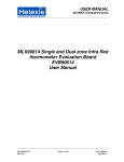
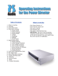
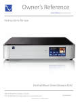
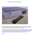
PerfectWave DirectStream DAC Upgrade Kit Thank you for purchasing the PerfectWave DirectStream DAC upgrade kit. The instructions that follow will assist you through the modifications necessary to upgrade your DAC to the DirectStream DAC. If you have any questions concerning your kit or the instructions please don’t hesitate to call us at PS Audio. We recommend you watch the installation video and then read this handbook completely and use it as a guide. PS Audio 4826 Sterling Dr. Boulder, CO 80301 p. 720 406 8946 f. 720 406 8967 15-‐061-‐97-‐1 Rev A. Owners Manual, DSD Upgrade Kit Page 1 of 24 Upon opening, your DSD Upgrade Kit will look like this: 15-‐061-‐97-‐1 Rev A. Owners Manual, DSD Upgrade Kit Page 2 of 24 15-‐061-‐97-‐1 Rev A. Owners Manual, DSD Upgrade Kit Page 3 of 24 Accessory Parts: 15-‐061-‐97-‐1 Rev A. Owners Manual, DSD Upgrade Kit Page 4 of 24 Tools: A pair of pliers may also be useful. These are not included in this kit. 15-‐061-‐97-‐1 Rev A. Owners Manual, DSD Upgrade Kit Page 5 of 24 Important: If your DAC is equipped with a bridge, be sure to install bridge update version 2.15 or higher before beginning the disassembly process. The bridge update procedure is included at the end of this document. Bridge update Procedure • • • • • • Starting from the bridge screen on your PWD MK1 or MK2, navigate to the network setup screen by pressing: the home icon, then the green edit button on the bridge input selection line, then the network icon. Write down the IP address listed . At a computer that is on the same local area network, open a web browser, and in the address line, type in the IP address for the PWD. This will take you to the web page for the PWD. Select Web upgrade. Copy and paste this link into the upgrade path field: http://updates.psaudio.com/bridge/upgrade-0.2.15a.ub Click on upgrade firmware. The upgrade process may take up to 30 minutes depending on your network connection speed. Disassembling your DAC Remove the Top Cover 1. Unplug your DAC from its power source and unplug the AC line cord from the rear panel of the DAC. 2. Find or create a padded work surface such as a table with a piece of carpet or rug. 3. Place your DAC upside down on the white cleaning cloth with the rear panel facing towards you. 4. Remove the felt pad shown in the photo below, and discard it. 5. With the Phillips screw driver, remove the four 4-40 head screws shown in circles below. No need to save these screws your kit has new ones. 15-‐061-‐97-‐1 Rev A. Owners Manual, DSD Upgrade Kit Page 6 of 24 6. Thread each one of the 4 pieces of “All Thread” into the 4 holes 6 turns each. Remove this felt pad 15-‐061-‐97-‐1 Rev A. Owners Manual, DSD Upgrade Kit Page 7 of 24 Caution: Be sure your work surface is protected as the “All Thread” screws may scratch the surface! 7. Flip the unit back over right side up on your protected work surface. 8. Uniformly push down on the sides of your DAC. The top will pop up as shown below. 9. Reach under the top cover and lift it out of the chassis, flip it over to the left and set it down on the left side of the DAC as shown in the photo below. 10. Unscrew the 4 pieces of “All Thread” from the top cover bracket and set aside. 11. Wiggle and pull the top cover ground wire from the grounding block. (Some DACs have this ground wire and some do not.) Pliers help. 12. Retrieve any pieces of gasket material that may have come off the top cover and fallen into the unit. There should be 9 pieces of gasket material on the top panel in the locations shown below. Replace any loose pieces by pressing them back onto the metal where shown below. Top Cover Ground Wire 9 Pieces of Gasket Material 15-‐061-‐97-‐1 Rev A. Owners Manual, DSD Upgrade Kit Page 8 of 24 Remove the Original Digital Input Board 13. CAUTION: Anti-static precautions are necessary when handling your new Direct Stream boards. Remove the wrist strap from the plastic bag, open up the loop and put it around your wrist and make it snug. 14. Attach the alligator to the center terminal (ground) of the AC inlet module as shown lower right, or to the ground distribution block inside the chassis. 15. Remove the 5 screws that secure the XLR, optical, and HDMI connectors to the rear panel (circles). No need to save these screws your kit has new ones. 16. Place the 1.5” X 0.755 nylon washer over the outside of the nut on the RCA connector to prevent the rear panel from being scratched and use the ½” open end wrench to remove the nut from the RCA connector. Use ½” open end wrench 17. Using your thumb and index finger, carefully rock the J10 ribbon cable back and forth out of the header as shown right. Set this cable aside for re-use. 18. Using the same method, unplug ribbon cable J11. This cable will be not used on the new assembly. 15-‐061-‐97-‐1 Rev A. Owners Manual, DSD Upgrade Kit Page 9 of 24 19. Unplug the ribbon cable or the UMC coax cables from J13 of the old input board. The J13 cable(s) will not be reused. 20. Remove the three 6-32 screws (squares) that hold the old board to the 3 spacers. 21. Lift the board out of the chassis moving it away from the rear panel. The piece of copper tape on the USB connector will peel off of the rear panel, this is ok. Copper Tape Unplug J10 Unplug J11 Remove J13 or UMC coax cables 22. Remove transformer. Squeeze connector tabs to release. Pull out transformer and remove mounting hardware. They will not be re-used. DISCONNECT MATE-‐N-‐LOCK CONNECTORS REMOVE 9/16” HEX NUT AND WASHERS 15-‐061-‐97-‐1 Rev A. Owners Manual, DSD Upgrade Kit Page 10 of 24 23. Remove back panel screws for Analog and Power Supply PC board assemblies. Remove nuts using box wrenches supplied and the large protective nylon washer to prevent scratching the powder coat surface. 24. Remove AC inlet and ground Faston connectors as shown. A pair of pliers will help with this step. Do not pull on the wires, only the connector. If a PS Bridge is present, remove it at this time. TB2, BLUE GROUND W7 GREEN/YELLOW STRIPE. TB1, BROWN WIGGLE OFF USING A ROCKING MOTION. 15-‐061-‐97-‐1 Rev A. Owners Manual, DSD Upgrade Kit Page 11 of 24 25. Remove 3 hex spacers,1-1/4” (squares) and set aside for reuse. Remove 8 x #6-32 X ¼” screws (circles). Remove and set aside the ribbon cable connecting the power supply board and the display board. Set aside for re-use. Pull Analog and Power Supply boards out and set aside. They will not be re-used. Ribbon cable 26. You have now completed the disassembly of your DAC. 15-‐061-‐97-‐1 Rev A. Owners Manual, DSD Upgrade Kit Page 12 of 24 Building your DirectStream DAC 1. Turn the chassis over and install the two hex spacers using #4-40 X ¼” flat head screws as shown. 2. Install the new felt pad over the transformer hole. 15-‐061-‐97-‐1 Rev A. Owners Manual, DSD Upgrade Kit Page 13 of 24 3. Installing the power supply board assembly a. Begin by checking to see that the gold fuses are installed and that the transformer wiring is the same as the previous board. b. Align the PCB with the back panel holes. c. Install a #6-32 X ¼” black SEMS screw into the back panel bracket next to the AC inlet. d. Install 6 each #6-32 X ¼” pan head screws to mount the PCB to the internal standoffs. e. Attach the AC wiring. i. Attach the Line wire (brown) to the tab labeled “TB1”. ii. Attach the Neutral wire (blue) to the tab labeled “TB2”. iii. Attach the Ground wire (green with a yellow strip) to the ground distribution block. 15-‐061-‐97-‐1 Rev A. Owners Manual, DSD Upgrade Kit Page 14 of 24 Note: Some versions of the PW DAC used Black instead of Brown for the Line wire and White instead of Blue for the Neutral wire. 4. Install the DirectStream Analog board assembly: a. If present, remove the finish nuts and lockwashers from the RCA jacks. b. Align rear panel components with the rear panel hole pattern and insert. c. Place lock washers and nuts on the RCA jacks and tighten as shown. Note the use of the nylon finish protection washer. 15-‐061-‐97-‐1 Rev A. Owners Manual, DSD Upgrade Kit Page 15 of 24 d. Insert screws attaching the PCB to the internal standoffs. Begin with 2 each #4-40 X ¼” black Sems screw in the two holes closest to the front panel. e. Insert 3 each #6-32 X 1-1/4” hex male-female spacer into the three holes closest to the rear panel. Finger tight only…no wrenches. 15-‐061-‐97-‐1 Rev A. Owners Manual, DSD Upgrade Kit Page 16 of 24 f. Insert 2 each #6-32 X ¼” pan head screws in the two remaining holes. 15-‐061-‐97-‐1 Rev A. Owners Manual, DSD Upgrade Kit Page 17 of 24 Install the DirectStream Digital board assembly 1. Place the PCB on the spacers and insert into the back panel holes. Be sure the optical receiver and the USB connector are centered in their holes. 2. Install the black washer and dress nut onto the RCA connector. Be sure to use the protective nylon washer as shown. 15-‐061-‐97-‐1 Rev A. Owners Manual, DSD Upgrade Kit Page 18 of 24 3. For each of the 3 XLR connectors, install 2 each XLR screws (M2.5mm X 8mm pan head ) 2 each I2S connector screws (M3mm X 6mm pan head sems screws 1 each Optical Receiver screw (#4-24 pan head screw 2 each Analog Board ground screws (#6-32 X ¼” black SEMS screw ) ) ) 15-‐061-‐97-‐1 Rev A. Owners Manual, DSD Upgrade Kit Page 19 of 24 4. Install 3 each #6-32 X ¼” pan head screws. Peel the backing off the copper tape and apply as shown so that the copper connects the USB connector and the back panel. Copper Tape 5. Install cable assemblies: a. Install the ribbon cables that mate the Power Supply board assembly to the Display Board assembly, and the Power Supply board assembly to the DSD digital board assembly. These are the same cables used on the previous assembly and they are identical. b. Install the new power supply cable between the Power Supply board and the DSD Analog board, and the new ribbon cable between the DSD Digital board and the DSD Analog board. 15-‐061-‐97-‐1 Rev A. Owners Manual, DSD Upgrade Kit Page 20 of 24 New Ribbon cable New Power Supply Cable Replacing the Top Cover 1. If your DAC has a top cover ground wire, reconnect it to the ground block in the rear corner of the chassis near the AC inlet. Re-install any EMI tabs that may have fallen off. See photo at the bottom of page 7. 2. Press the EMI foam back onto the rear flange of the top cover if it has lifted. See photo below on the right. 3. Flip the top cover over and lower it into the chassis rear first to ensure the EMI foam on the rear of the top cover gets captured inside the chassis as shown below. 4. Press back and down to drop the front of the top cover in place as shown below. 5. Carefully flip the unit over on its top and secure the top cover in place with four 4-40 flat head screws in locations shown in the center photo on page 5. 6. It is now ok to remove the wrist strap from your wrist and the DAC. 15-‐061-‐97-‐1 Rev A. Owners Manual, DSD Upgrade Kit Page 21 of 24 Rear flange EMI gasket foam inside the chassis Press back and down Update firmware and place the DirectStream DAC Label on the unit 1. Peel the back from the DirectStream DAC label and place it on the rear panel of your DAC in the location shown below. DirectStream DAC Place label here 15-‐061-‐97-‐1 Rev A. Owners Manual, DSD Upgrade Kit Page 22 of 24 Update the Firmware 2. Plug your DSD DAC back into the power source. 3. Remove the SD card from your DAC if you have one installed. Press to eject. You will no longer need this SD card. 4. Insert the SD card with the new firmware that came with your kit into your DSD DAC. The SD card included in your kit contains the latest firmware. Note: The SD card plugs into the socket upside down with the contacts facing up. 5. Turn the rear panel power switch ON. The logo button will flash for up to 2 minutes. Be patient and do not disturb the installation process. SD card contacts up DSD DAC Firmware Check System Information 6. From the DAC screen, press the ‘gear’ icon in the upper right corner of the screen. The version screen will appear. 7. The “Unit ID:” number should match the unit UID label on the rear panel and your DAC. You should also see a Bootloader version, a Firmware version, a CPLD version, a USB version, and a Bridge version if your DAC has a bridge card installed. The screen below is an example; some of your values will be different. 15-‐061-‐97-‐1 Rev A. Owners Manual, DSD Upgrade Kit Page 23 of 24 Your upgrade is now complete. 15-‐061-‐97-‐1 Rev A. Owners Manual, DSD Upgrade Kit Page 24 of 24