1
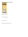
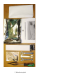
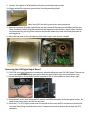
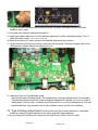
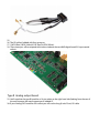
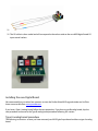
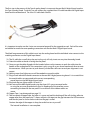
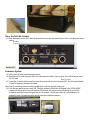
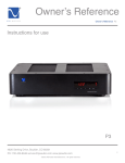
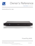
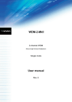
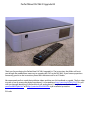
PerfectWave DAC Mk II Upgrade Kit
Thank you for purchasing the PerfectWave DAC Mk II upgrade kit. The instructions that follow will assist
you through the modifications necessary to upgrade your DAC to the DAC Mk II. If you have any questions
concerning your kit or the instructions please don’t hesitate to call us at PS Audio.
We recommend you first watch the installation videos and then use this handbook as a guide. The first video
to watch is how to remove the digital input board. It is located here: http://youtu.be/542U4yTFzJQ This will
walk you through identifying if you have the A or B analog board. From there, watch either the A http://
youtu.be/hBWYzjWxYmY or B http://youtu.be/fX3xCW6YFkA style installation procedure.
PS Audio
Your Kit Should Include the Following
2, 1A, Slow Blow Gold Fuses
1, DAC Mark II Name Plate
1, 1.5” X 0.75 Nylon Washer
1, DAC Mk II Firmware
Hardware images below shown actual size
2, Pieces Copper Tape
2, M2.5 Phillips Pan Head Metric Screws
1, 4-24 X 3/8” Tapping Screw
2, M3-0.5 X 6mm Phillips Pan Head Metric Screws
4, 4-40 X 3/8” Phillips Flat Head Screws
4, 4-40 X 11/2” All Thread
3, 6-32 X ¼” Phillips Pan Head Screws
1, White cleaning cloth
1, Upgrade manual
1, DAC II Input Board
1, PerfectWave Remote control II
1, Wrist Strap
1, 1, 9/16” wrench
1, ½” open end wrench
1, Plastic Tweezers
The Mezzanine Board.
1, 5/8” wrench
1, #1 Phillips screw driver
The I2S cables
Type A
Type B
Remove the Top Cover
1. Unplug your DAC from its power source and unplug the AC line cord from the rear panel of the DAC.
2. Find or create a padded work surface such as a table with a piece of carpet or rug.
3. Place your DAC upside down on the white cleaning cloth with the rear panel facing towards you.
4. With the Phillips screw driver, remove the four 4-40 flat head screws shown in circles below. No need
to save these screws your kit has new ones.
5. Thread each one of the 4 pieces of all thread into the 4 holes 6 turns each.
Caution: Be sure your work surface is protected as the all thread screws may scratch the surface!
6. Flip the DAC back over right side up on your protected work surface.
7. Uniformly push down on the sides of your DAC. The DAC will drop and the top will pop up as shown to
the right.
8. Reach under the top cover and lift it out of the chassis, flip it over to the left and set it down on the left
side of the DAC as shown in the photo below.
9. Unscrew the 4 pieces of all thread from the top cover bracket and set aside.
10.Wiggle and pull the top cover ground wire from the grounding block.
Note: Some DACs have this ground wire and some do not.
11.Retrieve any pieces of gasket material that may have come off the top cover and fallen into the unit.
There should be 9 pieces of gasket material on the top panel in the locations shown below. Replace
the loose pieces by pressing them back over the bracket where they came from.Note placement of
existing gasket.
12.Move the top cover on the soft cleaning cloth aside to gain work space as needed.
Top Cover
Ground Wire
Removing the Old Digital Input Board
13.CAUTION, anti-static precautions are necessary when handling your new DAC Mk II board. Remove the
9 Pieces of
wrist strap from
the Material
plastic bag, open up the loop and put it around your wrist and make it snug.
Gasket
14.Attach the alligator to the center terminal (ground) of the AC inlet module as shown lower right.
15.Remove the 5 screws that secure the XLR, optical, and HDMI connectors to the rear panel (circles). No
need to save these screws your kit has new ones.
16.Place the 1.5” X 0.755 nylon washer over the outside of the nut on the RCA connector to prevent the
rear panel from being scratched and use the ½” open end wrench to remove the nut from the RCA
connector.
17.Using your thumb and index finger, carefully rock the J10 ribbon cable back and forth out of the
header as shown right.
18.Using the same method, unplug ribbon cable J11.
19.Unplug the ribbon cable from J13 of the old input board and J3 of the analog board below. The J13
cable will not be reused. Use ½” open end wrench
20.Remove the three 6-32 screws (squares) that hold the old board to the 3 spacers.
21.Lift the board out of the chassis moving it away from the rear panel. The piece of copper tape on the
USB connector will peel off of the rear panel, this is ok.
Copper Tape
Unplug J10
22. Identifying Type A or Type B analog board
There are two types of analog boards. The analog board is the larger bottom board. How the Mark
II Digital Processor board connects to the analog board depends on whether it is an A or a B style of
analog board. The next step is to identify if you have either an A or a B style analog board. Once you
have identified the style, proceed to the A or B installation section to finish the installation.
23. Type A Analog output board. You’ll note that the Type A analog board has a small black
twelve pin socket (J3 page10) adjacent to the two large power supply capacitors.
24.If your Analog DAC board has this socket you will use the short (3 inch/7.5cm) I2S cable.
Unplug J11
Remove J13
25.
26.The I2S cable is labeled with four acronyms.
27.1.MCK (Blue) 2.BCK (Yellow)3.DAT (Red) 4.LRCK (White).
28. These acronyms will correspond to the colour code on the new MKll digital board I2S input coaxial
sockets.
Type B Analog output board.
29.You’ll note that the type B board has a 16 pin socket on the right hand side (looking from the rear of
the unit) between the metal support posts labeled J2 .
30.If your Analog DAC board has this socket you will use the long (6 inch/15cm) I2S cable.
31.
32.The I2S cable is colour coded and will correspond to the colour code on the new MKll digital board I2S
input coaxial sockets.
Installing the new Digital Board.
We recommend that you take a few moments to view the Perfect Wave MK ll upgrade videos on YouTube
these are accessible from www.psaudio.com.
If you have a Type A analog board, follow the next procedure. If you have a type B analog board, skip the
next procedure and move to the Type B analog board procedure following this section.
Type A analog board procedure
The following instructions assume you have removed your MK1Digital input board and have a type A analog
board.
The first step in the process of the Type A analog board is to connect the new Mark II digital Input board to
the Type A analog board. To do this you will connect the supplied short I2S cable between the Digital Input
board and the analog board. The short I2S cable looks like this:
It is important to make sure the 4 wires are connected properly for the upgrade to work. Each of the wires
are labeled to match the corresponding connections on the new Mark II Digital Input board.
The black long connector of this cable inserts into the analog board and the individual wires connect to the
matching connectors on the Digital Input board.
33.The I2s cable has a small tab or key on its plug so it will only insert one way into the analog board.
34.Orient the cable so the tab is facing the rear panel.
35.Once you get the cable aligned with the header below use the tweezers to push the cable into the
header on the analog board. This connection is only a snug fit so you do not need much force to mate
the connectors. When you start to push down if you feel the cable start to rock your alignment is not
correct.
36.Nothing more than light pressure will be needed to secure the cable.
37.Plug in each individual coaxial connector to the new MK II digital processing board. It is essential that
the coaxial cables are connected to the correct corresponding
coaxial input on the MKll digital Input board.
38.Plug back the two ribbon cables J10 and J11
39.Now reinstall the MKll digital board using the three 6-32 screws removed earlier
or using the new ones provided with your kit. Replace all of the interface screws
connecting the board to the rear panel. Ensure that all of the ribbon cables are
secure.
40.Copper Tape. (see photograph on page 12)
41.Take one piece of copper tape, the other is a spare, and peel the backing off the self-sticking adhesive
copper tape, form the tape to an “L” shape, and press the tape into the gap between the USB connector
and the rear panel as shown below to ensure the gap is sealed.
Caution: the edge of the copper is sharp, be careful not to cut yourself!
The Internal installation is now complete.
42.
This photograph shows a correctly installed I2s coax cable.
Move on to the final assembly section next and bypass the Type B assembly section.
Type B analog board procedure
The following
removed your MK1 Digital input board and have a type B analog
J3 instructions assume you have
Polarizing Tab
board.
The first step in the B analog model is to connect the I2S coaxial cable and mezzanine board assembly
between the type B analog board and the new Mark II Digital Input board. The proper cable assembly for
this process looks like this:
43.Step 1. Locate the 16 pin socket J2 on the analog board and insert the long cable and mezzanine board
into the socket. Make sure the board is correctly seated and that the coaxial connectors face in toward
the unit rather than toward the side of the unit.
44.Nothing more than light pressure will secure the cable.
45.Now reinstall the MKll digital board using the three 6-32 screws removed earlier
or using the new ones provided with your kit. Ensure that all of the ribbon cables are secure.
46.The next process involves plugging in the I2S coax connectors into the correct sockets on the digital
board. The coax cable is fragile and the space to work is limited so be patient and take your time with
this task. It may take you a few tries to get them plugged in. Note the color coding on both the I2S
cable and the on the MKll digital input board. These must match when connected.
47.Reconnect the original J10 and J11 ribbon cables so the assembly process between the two boards is
now complete.
48.Copper Tape. (see photograph on page 12)
Take one piece of copper tape, the other is a spare, and peel the backing off the self-sticking adhesive
copper tape, form the tape to an “L” shape, and press the tape into the gap between the USB
connector and the rear panel as shown below to ensure the gap is sealed.
Caution: the edge of the copper is sharp, be careful not to cut yourself!
The Internal installation is now complete.
Copper Tape
J10
Final assembly procedure for both Type A and Type B models
Below are the final steps to finishing your Mark II upgrade. These steps apply to both the type A and the
type B installation procedures.
49.Secure the XLR connector to the rear panel with the two M2.5 screws (pentagons). Do not over
tighten, these screws only need to be snug.
50.Secure the optical connector to the rear panel with the 4-24 X 3/8” Screw (circle). Do not over tighten,
these screws only need to be snug.
51.Secure the two HDMI connectors to the rear panel with the two M3-0.5 X 6mm Phillips screws
(diamonds). The tabs on the HDMI connectors are fragile so support them with your finger on the
inside of the rear panel while you start the screw into the connector tab. These screws only need to be
J11
snug.
52.Put the black washer on the RCA connecter followed by the gold nut.
53.Place the 1.5” X 0.755 nylon washer over the outside of the double “D” nut and use the ½” open end
wrench to tighten the nut on the RCA connector; do not over tighten, it only needs to be snug, about
½ turn.
Changing the Fuses
54.Lift off the fuse cover and fuse with the back of the tweezers shown below left.
Note: Both of the fuses are the same so you don’t need to worry about mixing them up.
55.Locate the fuse F1 and F2 on the power supply board near the AC inlet module.
56.Remove the old fuse by twisting it out from under the latches and insert the gold fuse by snapping it
into the fuse cover latches as shown below right.
57.Replace the fuse by snapping the fuse
cover
fuse back
into the socket.
Use ½”
openand
end Wrench,
Snug
Replacing the Top Cover
58.If your DAC has a top cover ground wire, reconnect it to the ground block in the rear corner of the
chassis near the AC inlet. See photo at the center of page 5.
59.Press the EMI foam back onto the rear flange of the top cover if it has lifted. See photo below on the
right.
60.Flip the top cover over and lower it into the chassis rear first to ensure the EMI foam on the rear of the
top cover gets captured inside the chassis as shown below.
61.Press back and down to drop the front of the top cover in place as shown below.
62.Carefully flip the unit over on its top and secure the top cover in place with the four 4-40 flat head
screws in locations shown in the center photo on page 4.
63.It is now ok to remove the wrist strap from your wrist and the DAC.
Place the DAC Mk II Label
64.Peel the back from the DAC Mk II label and place it on the rear panel of your DAC in the location shown
below.
Press Back
and Down
EMI Foam
Rear Flange
EMI Gasket Foam
Inside the Chassis
Firmware Update
65.Plug your DAC back into the power source.
66.Remove the SD card from your DAC if you have one installed. Press to eject. You will no longer need
this SD card.
Place Label here
67.Insert the SD card with the new firmware that came with your kit into your DAC. The SD card included
in your kit contains the latest firmware.
Note: The SD card plugs into the socket upside down with the contacts facing up.
68.Turn the rear panel power switch ON. The logo button will flash for 40 seconds, the “INITIALIZING”
screen with the progress bar will show for 55 seconds, the progress bar will remain at its end for
6 seconds, then the screen will go blank for 10 seconds. At this point the DAC will initialize to its
operating state. Be patient and do not disturb the installation process.
SD Card up Side Down
Checking System Information
69.Turn the rear panel switch OFF and then ON again. Once the “INITIALIZING” screen appears, tap the
center of the display to enter the information screen shown below.
70.The “Unit ID:” number should match the unit UID label on the rear panel and your DAC. You should
also see a Bootloader version, a Firmware version, a CPLD version, a USB version, and a Bridge version
if your DAC has a bridge card installed. The screen below is an example; some of your values will be
different.
Your upgrade is now complete. Happy listening!