1
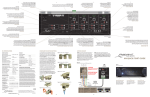
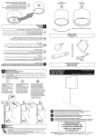
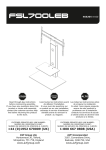
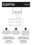
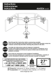
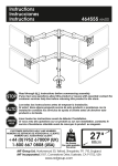
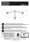
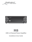
PROFICIENT ONE
Universal IR Kit
Owner’s Manual
DESCRIPTION
Proficient One is a universal IR Receiver Kit that can be adapted to almost any surface
mount, flush mount or shelf mount application. It includes all of the parts necessary for
installing a single-room IR Repeater System for controlling a TV, Audio/Video Receiver,
Blu-ray player, Cable Box, Satellite Receiver...just about any IR controlled A/V home entertainment device.
The kit includes an IR Receiver that can be attached to the front of a TV, or extended from
behind on flat panel TVs that have a minimal frame around the display area. The receiver
can also be adapted to a low-profile shelf-top case or cabinet door adapter for controlling IR components hidden in an equipment cabinet.
The Proficient One IR Receiver adapts and connects in minutes! Please read the instructions in this manual carefully to enjoy arm chair control of your favorite audio/video
components!
FEATURES
• IR Receiver shelf mount, flush mount, surface mount and TV mount adapters allow
installation almost anywhere
• IR Receiver compatible with most Plasma, LCD and LED TVs
• IR Receiver compatible with most CFL light bulbs
• Includes one IR Router, one IR Power Supply, and two IR Dual Flashers for easy system installation
SPECIFICATIONS
•
Infrared carrier frequency bandwidth: 30 - 60 kHz
•
Reception range: Up to 80 feet*
•
Reception angle: +/- 45º
•
Cable requirements: See section: Extending The Receiver Wire
•
Max. Transmission length: 1 mile using 18 gauge wire
•
Maximum current output: 100mA
•
IR Receiver Dimensions: .55" diameter (14mm)
•
Power requirements: +12VDC, 100mA
* Depending on remote control output strength and ambient conditions.
2
WHAT’S INCLUDED
1 - Proficient One IR Receiver
1 - Tabletop Adapter
1 - Flush Mount Adapter
1 - TV Mount Adapter
1 - IR Router
2 - Dual IR Flashers
1 - IR Power Supply
1 - BOT-1.0 IR Terminal
1 - PTP-1 Plug to Plug Jumper
1 - IR Parallel Block
3
READ THIS BEFORE YOU DO ANYTHING!
FOUR IMPORTANT CONSIDERATIONS
1. Where is the IR Receiver going to be located? The IR Receiver must be ‘line-ofsight’ to the remote control being used to be able to control the system audio/video
components. This location should be in a convenient spot in front of the user when
seated in a typical location for watching TV or listening to music. This will determine
how the IR Receiver is going to be mounted.
2. How is the IR Receiver going to be mounted? The IR Receiver can be surface
mounted directly to the frame on the front of some flat panel TVs. For TVs that
do not have a wide enough frame, the TV Mount Adapter can be used to extend
the IR Receiver out from the back or side of the TV. If the IR Receiver is going to be
mounted in a cabinet door, the Flush Mount Adapter will mount the IR Receiver in
an 11/16" hole in the cabinet door. If the IR Receiver is going to be placed on a shelf or
on top of a cabinet, the Tabletop Adapter provides an attractive, low profile case for
that application.
3. Where are the audio/video components that are going to be controlled?
The IR Receiver, Flashers and Power Supply all connect to the IR Router. The IR
Router should be in the same location as the audio/video components. If the A/V
components are in a wall unit or cabinet in the same room and within a few feet
of the IR Receiver, then once the IR Receiver has been mounted, find a convenient
location that allows access to the IR Router for making connections and then simply
connect the IR Receiver, Flashers and Power Supply. (The IR Receiver has a total wire
length of 6 feet, 8 inches, and the Flashers have a wire length of 8 1/2 feet, usually
enough wire to make connections in a typical cabinet or wall unit.)
If the IR Receiver is going to be mounted across the room or in a different room
from the A/V components, the wire length of the IR Receiver can be extended to
accommodate those situations. Please see the section: Extending the Receiver
Wire for additional information.
4. IMPORTANT NOTE - Placement - The IR Receiver should be located so that it is not
directly facing a light source such as sunlight, lamps or video displays (CRT, LCD, and
Plasma). When mounted near a display, it should be flush to the display and away
from light reflections that may occur.
With answers to these three important questions, you’re ready to install your Proficient
One IR Receiver...So let’s go!
4
INSTALLING THE IR RECEIVER
Front of TV
Attach with
Adhesive
Attach with
Adhesive
To IR Router
RCVR Jack
PROFICIENT
ONE
IR Receiver
PROFICIENT ONE
Electronics Module
8” Receiver Cable
Diagram 1 - Surface Mount - Flat Panel TV
SURFACE MOUNT
The first, and easiest option, is to mount the IR Receiver on the front frame of a flat panel
TV. This application can also be used to surface mount the IR Receiver to other objects.
1. Select a location on the TV frame to mount the IR Receiver. Be sure the receiver will
not be blocked by any object to allow ‘line-of-sight’ to the remote control in normal
use.
2. With the IR Receiver 8" Receiver Cable directed toward the edge of the TV, using
one of the included adhesive strips, carefully attach the IR Receiver to the TV frame.
Diagram 1
3. Carefully flatten and wrap the 8" Receiver Cable around to the back of the TV. The
Receiver Cable can be secured to the TV with tape or a wire holder if necessary. Do
not block any TV vents.
4. Using one of the round adhesive strips, carefully attach the Electronics Module to
the rear of the TV. Do not block any TV vents.
5. Carefully run the plug end of the Receiver Cable into the cabinet with the A/V
components to where the IR Router will be located. Be careful not to pinch or strain
the Receiver Cable. The Receiver Cable can be secured to the back of the TV with
tape or a wire holder. Do not block any TV vents.
If this is your application, when finished, proceed to section: Typical Connections.
5
INSTALLING THE RECEIVER
Front of TV
Attach with Adhesive
Flat
End
Attach with Adhesive
PROFICIENT ONE
Electronics Module
To IR Router
RCVR Jack
PROFICIENT ONE
TV Mount Adapter
Attach with Adhesive
8” Receiver Cable
PROFICIENT ONE
IR Receiver
Front of TV
PROFICIENT ONE
Electronics Module
To IR Router
RCVR Jack
Attach with
Adhesive
Ridged End Flat End
PROFICIENT
ONE
PROFICIENT ONE
IR Receiver
TV Mount Adapter
Attach with 8” Receiver Cable
Adhesive
Ridged End
Diagram 2 - TV Mount Adapter Rear Mount
Diagram 3 - TV Mount Adapter Bottom/Side Mount
TV MOUNT ADAPTER
The TV Mount Adapter allows mounting the IR Receiver on an extension
attached to the rear or side of a flat panel TV that does not have a frame
on the front that is wide enough to directly mount the IR Receiver. This
application can also be used to mount the IR Receiver in just about any
position on just about any object.
360°
Both ends of the TV Mount Adapter rotate and swivel allowing the Adapter
and IR Receiver to be manipulated into different positions as shown in
Diagram 4.
1. Select a location on the TV to mount the TV Mount Adapter. Be sure that
once mounted, the IR Receiver will not be blocked by any object to allow
‘line-of-sight’ to the remote control in normal use.
2. With the 8" Receiver Cable aligned to the Wire Gap on the ridged
180°
end of the TV Mount Adapter, (Diagram 5) using one of the round,
Diagram 4
notched adhesive strips, attach the IR Receiver to the TV Mount Adapter.
Flat End
Diagrams 2 & 3
3. Using one of the round adhesive strips, attach the flat end of the TV
Mount Adapter to the TV frame. Diagrams 2 & 3 & 5
4. Carefully flatten and wrap the 8" Receiver Cable around to the back of
the TV. The Receiver Cable can be secured to the TV with tape or a wire
holder if necessary. Do not block any TV vents.
5. Using one of the round adhesive strips, attach the Electronics Module to
the rear of the TV. Do not block any TV vents.
Diagrams 2 & 3
6. Carefully flatten and wrap the plug end of the Receiver Cable into the
cabinet with the A/V components. Be careful not to pinch or strain the
Receiver Cable. The Receiver Cable can be secured to the back of the
TV with tape or a wire holder. Do not block any TV vents. If this is your
application, when finished, proceed to section: Typical Connections.
6
Wire
Gap
Ridged End
Diagram 5
INSTALLING THE RECEIVER
Receiver Cable
Pass-Through
Tabletop Adapter
Top Inside
Base Lock
Wide Gap
At Top
Base Locks
Lens
IR Receiver
Base Lock
Electronics
Module
Socket
8” Receiver Cable
IR Receiver
Lens
Receiver Cable
Base Lock
Tabletop Adapter Base - Pass-Through
Inside
Diagram 6 - Tabletop Adapter Insert IR Receiver
Electronics
Module
‘Bottom Notch’
Base Lock
To IR Router
RCVR Jack
Diagram 7 - Tabletop Adapter Insert Electronics Module
TABLETOP ADAPTER
The Tabletop Adapter allows mounting the
IR Receiver in an attractive low-profile case
creating an IR Receiver that can be placed on
any shelf or tabletop.
Rotate Clockwise
to Tighten
Lens
Rotate Counter-clockwise
to Remove
1. Remove the Tabletop Adapter Base by
rotating it counter-clockwise as shown in
Diagram 8.
2. Position the Tabletop Adapter top so the
lens is facing down as shown in Diagram 6.
To IR Router
RCVR Jack
Diagram 8 - Tabletop Adapter Remove/Tighten Base
3. With the 8" Receiver Cable on the IR
Receiver facing up, carefully insert the IR Receiver into the socket on the backside of
the lens as shown in Diagram 6. The receiver should snap into place when properly
inserted.
4. With the ‘bottom notch’ of the Electronics Module facing you, carefully slide the
module onto the post in the Electronics Module Socket as shown in Diagram 7.
5. Carefully wrap the 8" Receiver Cable around the Electronics Module and extend the
plug end of the Receiver Cable out of the Tabletop Adapter case via the Receiver
Cable Pass Through as shown in Diagram 7.
6. Align the Adapter Base to the Adapter Top with the ‘wide gap’ aligned at the top
with the IR Receiver as shown in Diagram 7. Tighten the base to the top as shown in
Diagram 8.
If this is your application, when finished, proceed to section: Typical Connections.
7
INSTALLING THE RECEIVER
Cabinet Door
Cabinet Door
Flush Mount
Adapter Bezel
Push IR Receiver
until it snaps into place
11/16” (17.4mm)
Diameter Hole
8” Receiver Cable
5/8” (15.9mm)
Door Panel
Diagram 9 - Flush Mount Adapter 11/16" Hole
Diagram 10 - Flush Mount Adapter Install IR Receiver
FLUSH MOUNT ADAPTER
The Flush Mount Adapter allows mounting the IR Receiver in an equipment cabinet door.
This allows IR controlled audio/video components to be controlled with the cabinet door
closed.
This application requires drilling an 11/16" (17.4mm) hole in the cabinet door as shown in
Diagram 9. It is recommended that the IR Receiver be mounted closer to the hinged side
of the cabinet door so the Electronics Module can be mounted to an inside wall rather
than the door.
1. Select a location on the cabinet door to mount the Flush Mount Adapter. Be sure to
leave adequate clearance from the back of the cabinet door to the front of the A/V
components to allow room for the Adapter Locks with the door closed. (Diagram
12) Also be sure that once mounted, the IR Receiver will not be blocked by any
object to allow ‘line-of-sight’ between the remote control and the IR Receiver in
normal use.
2. Drill an 11/16" (17.4mm) diameter hole in the cabinet door. Diagram 9
3. From the back side of the cabinet door, feed the IR Receiver through the hole in the
cabinet door. Carefully pull the 8" Receiver Cable straight back from the IR Receiver
and with the receiver lens oriented to match the orientation of the adapter (thick
sections 12 and 6 o’clock) push the IR Receiver into the back of the adapter until it
snaps into place. Diagram 10
4. Pinch the Adapter Locks together and carefully slide the adapter/receiver assembly
through the hole until the adapter bezel is pressed against the front of the cabinet
door. Be sure to align the thick sections of the bezel at 12 and 6 o’clock for best left
to right off-axis performance. (It will look better that way as well.) Diagram 11
8
INSTALLING THE RECEIVER
Pinch Adapter Locks
together so they will slide
through hole in cabinet door
Cabinet Door
11/16” (17.4mm)
Diameter Hole
Cabinet Door
8” Receiver Cable
8” Receiver Cable
Adapter Bezel
Leave adequate space between the Adapter Locks
and the A/V components with the cabinet door closed.
Diagram 11 - Flush Mount Adapter Install Adapter
Diagram 12 - Flush Mount Adapter Adapter Installed
5. NOTE: It is recommended that the
Electronics Module be mounted to an
inside wall of the cabinet. If attached with
adhesive, there is some possibility that if
mounted to the door, in time, the module
could come loose from the action of the
door opening and closing and ultimately
fall off, potentially damaging the IR
Receiver the Electronics Module or both.
Using an appropriate length wood screw (not
included) attach the Electronics Module to an
inside wall of the cabinet. Use a screw that will
secure the module but will not penetrate the
outside wall of the cabinet. Do not overtighten
the screw to avoid damaging the Electronics
Module case. Diagram 13 OR...
Use one of the included adhesive strips to
attach the Electronics Module to the inside of
the cabinet.
6. Carefully run the plug end of the Receiver
Cable to where the IR Router will be located.
Be careful not to pinch or strain the cable.
If this is your application, when finished, proceed to
section: Typical Connections.
9
Cabinet Door
Flush Mount
Adapter Bezel
8” Receiver Cable
Use wood screw or
adhesive to attach
Electronics Module to
back of cabinet door or
inside wall of cabinet.
Electronics
Module
To IR Router
RCVR Jack
Diagram 13 - Flush Mount
Adapter Secure Electronics Module
TYPICAL CONNECTIONS
DVD
To extend wire length,
cut here.
Electronics Module
Proficient One IR Receiver
mounts directly on a
flat panel TV frame or
to one of the included
TV, Tabletop or Flush
Mount Adapters
PROFICIENT ONE
IR Reciver
Remote Control
Cable
IR Dual
Flasher
IR Flasher
w/red LED
A/V Receiver
IR Power
Supply
PTP-1.0
12VDC
Regulated
500mA
To 120V AC
(unswitched)
IR Router
PTP-1.0
Plug to Plug
Jumper Cable
Diagram 14 - Typical Connections
SINGLE ROOM - EQUIPMENT CABINET
With the IR Receiver configured and installed in a surface mount, TV mount, flush mount
or tabletop application as described on the previous pages, install the IR Router and then
connect the IR Receiver, Flashers and Power Supply to the IR Router as described below.
1. Find a convenient location in the equipment cabinet to mount the IR Router. This
location should allow easy access for making connections and be located so the IR
Receiver, Flasher and Power Supply wires can all be connected without modification.
Attach the IR Router to a cabinet wall or shelf with the included adhesive strip or
wood screws. Be sure the screws are long enough to secure the Router but not so
long that they extend out of the side of the cabinet.
2. Connect the IR Receiver to the “IR RCVR” jack on the IR Router.
3. Carefully position one IR Flasher over the IR Eye on each audio/video component to
be controlled. (If the eye is not obvious, shine a small flashlight into the front panel
of the component to locate the eye, or refer to the component’s owner’s manual.)
4. Position the IR Flasher so the mini-wire is positioned toward the nearest top or
bottom edge on the component being controlled.
5. Carefully wrap the Flasher mini-wire around to the back of the component and
run the Flasher wire to the IR Router, being careful to not pinch the wire between
components.
6. Connect the Dual Flasher to one of the “IR Flashers” jacks on the IR Router . Repeat
for all Flashers.
10
TYPICAL CONNECTIONS
7. As an option, use the PTP-1 Plug to Plug Jumper Cable to connect a Flasher OUT on
the IR Router to a device with a 3.5mm mini IR IN jack. If it doesn’t work, use an IR
Flasher for IR control.
8. Connect the IR Power Supply to the “12VDC Regulated” jack on the IR Router.
Connect the Power Supply to an UNSWITCHED AC outlet.
9. To test, point an IR Remote at the Proficient One IR Receiver. Press a specific function
button on the remote (Cable/Satellite ON/OFF for example). All connected Flashers
should flash red, and the selected component should respond to the command
(Cable/Satellite ON/OFF).
If any of that didn’t happen, check IR system connections and try again. If the system
still hasn’t responded, check the Troubleshooting section at the end of this manual.
EXTENDING THE RECEIVER WIRE
In some applications it may be necessary to extend the IR Receiver wire. Typical examples
would be if the IR Receiver is going to be located across the room from the IR Router and
A/V components or if the IR Receiver is going to be located in a remote room. This will
give the user the ability to control IR controlled audio/video components from a location
where the remote control no longer has direct line-of-sight to the equipment.
To extend the IR Receiver wire, use the included BOT-1.0 IR Terminal as shown in Diagram
17 or the IR Parallel Block as shown in Diagram 18. Use unshielded, 3-conductor
stranded wire as detailed in the Wire Length/Gauge Table on the next page.
IMPORTANT NOTE: DO NOT EXTEND THE WIRE LENGTH BETWEEN THE IR RECEIVER
AND THE ELECTRONICS MODULE. THIS WILL REDUCE THE SENSITIVITY OF THE IR
RECEIVER AND VOID THE WARRANTY. IF IT IS NECESSARY TO EXTEND THE WIRE LENGTH
TO THE IR ROUTER WITHOUT USING THE BOT-1.0 IR TERMINAL, EXTEND THE WIRE THAT
RUNS BETWEEN THE ELECTRONICS MODULE AND 3.5MM MINI PLUG (DIAGRAM 15).
SEE DIAGRAM 16 FOR THE WIRE PIN-OUT OF THE RECEIVER WIRE. USE THE IR PARALLEL
BLOCK TO MAKE CONNECTIONS AS SHOWN IN DIAGRAM 18.
Do not cut to extend wire length
Cut this section to extend wire length
Electronics Module
Diagram 15 - Only Extend The Plug End of the IR Receiver Cable
11
TYPICAL CONNECTIONS
Use unshielded, 3 conductor
stranded wire per the table, when
extending the plug end of the IR Receiver Cable. (4 conductor provides
an extra wire for back-up if one of
the conductors gets damaged.)
IR WIRE LENGTH
IR WIRE GAUGE
UP TO 200’ (61m)
24 AWG
UP TO 600’ (183m)
22 AWG
UP TO 2000’ (610m)
20 AWG
UP TO 5000’ (1524m)
18 AWG
GOLD = +12V
GND (RING)
RED = GND
+12VDC (SLEEVE)
IR SIGNAL (TIP)
BLUE = IR
Diagram 16 - 3.5mm Stereo Mini Plug & Wire Pin-Out
When adding wire length, as a first option, use the BOT-1.0 (Diagram 17). This will allow
complete installation without having to cut the IR Receiver wires. The IR Parallel Block
(Diagram 18) has been included as a second option for that type of connection when
desirable. Confirm that the IR Signal, +12VDC and GND wires are properly connected
to both the BOT-1.0 or IR Parallel Block and the IR Router (Signal to Signal; +12 to +12;
GND to GND). Improper connection will affect performance and possibly damage the IR
Receiver. The Proficient One Warranty does not cover this type of damage.
While it is possible to make wired connections without the BOT-1.0, IR Parallel Block or
IR Router, it is not recommended. Their use will reduce installation time, help eliminate
errors, allow easy troubleshooting and permit easy system upgrades later, if needed.
8” Receiver Cable
(Do Not Add Length!)
DVD
PROFICIENT ONE
IR Receiver
Hand Held
IR Remote
IR Flasher
w/red LED
Electronics Module
IR Dual
Flasher
BOT-1.0
IR Terminal
Cable
PTP-1.0
IR Flasher
w/red LED
A/V Receiver
6’ Reveiver Cable
(OK to Add Length)
3-Conductor
Extension Cable
(unshielded)
PTP-1.0
Point to Point
Jumper Cable
IR Power
Supply
12VDC Regulated
500mA
REMOTE ROOM
To 120V AC
(unswitched)
MAIN ROOM
Diagram 17 - Extending the Plug End of the IR Receiver Cable
12
TYPICAL CONNECTIONS
DVD
PROFICIENT ONE
IR Receiver
Electronics Module
IR Flasher
w/red LED
Hand Held
IR Remote
IR Dual
Flasher
Cable
PTP-1
IR Flasher
w/red LED
A/V Receiver
+12V
GND
IR
3-Conductor
Extension Cable
(unshielded)
IR Parallel Block
PTP-1
Plug to Plug
Jumper Cable
IR Power
Supply
REMOTE ROOM
12VDC Regulated
500mA
To 120V AC
(unswitched)
Electronics Module
PROFICIENT ONE
Hand Held
IR Remote
IR Receiver
MAIN ROOM
Diagram 18 - Multi-Room Application
MULTI-ROOM APPLICATION
Another application is multi-room IR control. If an audio receiver or amplifier is being used
to drive speakers in multiple rooms, it may be desirable to place an IR Receiver in some or
all of those rooms to control the audio components from another room. In many cases,
this same application can be used to control the main zone and second zone of a two-zone
A/V Receiver.
This will allow a user to turn the system ON/OFF with an IR remote via the IR Receiver(s)
in the remote room(s). The system can also be controlled from the main room with an IR
remote using the IR Receiver in the main room.
Installation combines the connections described in the previous Single Room and Extending
the Wire sections. The Main Room IR Receiver gets connected to the ‘IR RCVR’ jack on the
IR Router and the multi-room receiver(s) get connected to the screw terminals on the IR
Router using either the BOT-1.0 (Diagram 17) or IR Parallel Block (Diagram 18).
13
IR TROUBLESHOOTING GUIDE
NOTE: Due to the many variables in a given installation, the troubleshooting measures
you may need to take can vary in different situations.
Each installation is different due to the number of IR Receivers, length of wire runs, type
of wire, amount of ambient IR noise present, etc….
Therefore, your troubleshooting measures for a particular job can range from nothing at
all, to any combination of the solutions listed below.
Symptom #1: IR Flashers dimly lit or flickering.
Cause
Solution
1.
Signal and ground wires are
reversed or shorted either at the
IR Router or IR Receiver.
Recheck wiring.
2.
Defective Flasher.
Replace Flasher.
3.
Relatively high levels of ambient
light noise. This can be due to any
of the following: sunlight, florescent lighting or Plasma Displays.
Reposition the IR Receiver away from the
light source or eliminate the light source.
4.
EMI induced noise (electromagnetic interference). This can be
due to light dimmer controls or
other radiating electronic devices
(PC’s or any poorly shielded electronic device).
Reposition the IR Receiver and/or cabling
away from emitting device. You can also
place a 470-ohm resistor in parallel with
the IR Signal and GND connections on
the IR Router. This will also help alleviate
any stray capacitance in the cable.
5.
Plasma Interference.
Plasma interference can be reflected off
of any item it comes into contact with
within approx. 3 feet of the front of the
display. Keeping this in mind, make
sure that the IR Receiver is free from any
object that might reflect Plasma interference into the receiving eye.
14
IR TROUBLESHOOTING GUIDE
Symptom #2: IR Flashers constantly on.
Cause
Solution
1.
Plasma Interference
Plasma interference can be reflected off
of any item it comes into contact with
within approx. 3 feet of the front of the
display. Keeping this in mind, make
sure that the IR Receiver is free from any
object that might reflect Plasma interference back into the receiving eye.
2.
Voltage and Ground wires are
reversed at the IR Router or IR
Receiver
Recheck wiring.
3.
Relatively high levels of ambient
noise. This can be due to any of
the following: sunlight, florescent
lighting or Plasma Displays.
Reposition the IR Receiver or eliminate
the light source.
4.
EMI induced noise (electromagnetic interference). This can be
due to light dimmer controls or
other radiating electronic devices
(PC’s or any poorly shielded electronic device).
Reposition the IR Receiver and/or cabling
away from emitting device. You can also
place a 470-ohm resistor in parallel with
the IR Signal and GND connections on
the IR Router. This will also help alleviate
any stray capacitance in the cable.
5.
Power Supply not putting out
proper voltage.
Verify supply is a 12VDC regulated supply
reading between 11.5 to 13VDC under
load. Use the included 12VDC Regulated,
500mA Power Supply.
15
IR TROUBLESHOOTING GUIDE
Symptom #3: Intermittent IR control (i.e. buttons on remote need to be
pressed multiple times)
Cause
Solution
1.
Plasma Interference.
Plasma interference can be reflected off
of any item it comes into contact with
within approx. 3 feet of the front of the
display. Keeping this in mind, make
sure that the IR Receiver is free from any
object that might reflect Plasma interference back into the receiving eye.
2.
Relatively high levels of ambient
noise. This can be due to any of
the following: sunlight, florescent
lighting or Plasma Displays.
Reposition the IR Receiver or eliminate
the light source.
3.
Long Wire Runs – shielded wire
typically of 100 feet (30 meters)
or longer causes a filter effect due
to accumulated capacitance of
the wire. Intermittent, or no IR
control, could actually be because
of the longer wire runs.
Putting a 470-ohm resistor in parallel at
the IR Router between signal and ground
will effectively discharge the capacitance
of the wire. Adding a resistor between
the input and ground of the IR Router
will drop the IR level down somewhat. A
non-amplified connecting block, such
as the IR Router, may not have enough
signal output for consistent control of the
equipment.
4.
Low batteries in Remote
Replace batteries.
5.
Flasher placement is correct but
the signal is overpowering the
unit or there is bleed-through
from other Flashers close by.
If the A/V source (i.e. cable box, DVR or
satellite box) sees the IR signal twice, the
source will not process it correctly. Place
a piece of black electrical tape over the
Flasher to block reflected IR signals.
16
IR TROUBLESHOOTING GUIDE
Symptom #4: IR Flashers flash but some (or all) components do not
respond.
Cause
Solution
1.
Flasher placement is incorrect.
Reposition the Flasher so that it is directly over the component’s IR eye. Shine
a small flashlight into the front panel
of the component to locate the eye or
consult the component’s owner’s manual
for the exact location of the IR eye.
2.
Flasher placement is correct but
the signal is overpowering the
unit or there is bleed-through
from other Flashers close by.
Reposition the Flasher so it is not directly
over the IR eye to reduce the amount of
IR signal the IR eye on the component
being controlled ‘sees’. If the A/V source
(i.e. cable box, DVR or satellite box) sees
the IR signal twice, the source will not
process it correctly. Place a piece of black
electrical tape over the Flasher to block
reflected IR signals.
17
IR TROUBLESHOOTING GUIDE
Symptom #5: Absolutely No Functionality
(How to determine which component is at fault)
Component to Test
Instructions
1.
Verify Power Supply
With a Multimeter, measure the DC Voltage of the
Power Supply while it is connected to the IR Router.
Put the negative lead of the meter on the terminal
marked GND and the positive lead on the terminal
marked 12VDC (or V). You should get a reading
between 11.5VDC and 13.0VDC. If not, remove the
supply from the IR Router and measure again - this
time directly on the 2.5mm coaxial plug. If it reads between 11.5VDC and 13VDC, the Power Supply is most
likely good. Reconnect to the IR Router and proceed
to Step 2. NOTE: In most cases this will indicate the
Power Supply is good but in some cases the Power
Supply can still be bad (i.e. reads good when not
plugged in but may not be able to handle the current
load of the system.)
2.
Verify Flasher. (Proficient Dual-Visible IR
Flasher)
Remove the Power Supply from the IR Router and all
Flashers from the output. Place a jumper wire on the
IR Router between IR and +12V. Reconnect the Power
Supply and one Flasher. The Flasher should light
bright and solid. Repeat for all Flashers.
18
NOTES
19
LIMITED LIFETIME WARRANTY
Proficient Audio Systems (“Proficient”) warrants to the original retail purchaser only (“you”) that this product will be free from defects
in materials and workmanship for life (the “Warranty Period”), subject to the limitations and exclusions set out in this Limited Warranty.
This warranty is not transferable to subsequent owners of the product. If you discover a defect in material or workmanship within the
Warranty Period, you can obtain warranty service by contacting Proficient during the Warranty Period at 800.472.5555 or techsupport@
proficientaudio.com or by sending the product to Core Brands at 12471 E. Riverside Drive, Eastvale, CA 91752 or to the dealer from
whom you purchased the product. Defective products must be shipped, prepaid and insured, together with proof of purchase. Warranty service requests made without proof of date of purchase will be denied. Freight collect shipments will be refused. It is preferable
to ship this product in the original shipping container to lessen the chance of transit damage. In any case, the risk of loss or damage in
transit is to be borne by the purchaser.
If, upon examination by Proficient or its authorized dealer, it is determined that the unit is in fact defective, Proficient will, at its option:
• Repair or replace the product at no additional charge; or
• If the model is no longer available and can not be repaired effectively, replace the unit with a current model of equal or greater
value. In some cases where a new model is substituted, a modification to the mounting surface may be required. If mounting surface
modification is required, Proficient assumes no responsibility or liability for such modification.
Proficient will bear the cost of returning the repaired or replaced product to you, freight prepaid. All replaced parts and product become the property of Proficient Audio Systems. The foregoing is your sole and exclusive remedy for breach of warranty. If the product
is not found to be defective, Proficient will contact you to arrange for return of the product to you, at your expense.
EXCLUSIONS:
• This Warranty does not include service or parts to repair damage caused by accident, disaster, misuse, abuse, negligence, inadequate packing or shipping procedures, commercial use, voltage inputs in excess of the rated maximum of the unit, or service,
repair or modification of the product by unauthorized dealers. This Warranty also excludes normal cosmetic deterioration caused by
environmental conditions.
• This Warranty will be void if:
• the Serial Number on the product has been removed, tampered with or defaced.
• the product was not purchased from an authorized dealer.
THE FOREGOING WARRANTIES ARE EXCLUSIVE AND IN LIEU OF ALL OTHER EXPRESSED AND IMPLIED WARRANTIES. PROFICIENT
EXPRESSLY DISCLAIMS ALL SUCH OTHER WARRANTIES, INCLUDING BUT NOT LIMITED TO IMPLIED WARRANTIES OF MERCHANTABILITY, FITNESS FOR A PARTICULAR PURPOSE AND NON-INFRINGEMENT. In no event will Proficient be liable for any incidental
or consequential damages arising out of the use or inability to use the product, even if Proficient has been advised of the possibility of
such damages, or for any claim by any other party. Notwithstanding the above, if you qualify as a “consumer” under the Magnuson-Moss
Warranty Act, then you may be entitled to any implied warranties allowed by law for the Warranty Period. Further, some states do not
allow limitations on how long an implied Limited Warranty lasts or allow the exclusion or limitation of consequential damages, so such
limitations may not apply to you.
ATTENTION TO OUR VALUED CONSUMERS:
To insure that consumers obtain quality pre-sale and after-sale support and service, Proficient products are sold exclusively through
authorized dealers. Proficient products are not sold online by Proficient or its authorized dealers, and this warranty is VOID if the
products have been purchased from any internet reseller. To determine if your Proficient reseller is authorized, please call Proficient at
800.472.5555 or go to proficientaudio.com.
For technical inquires, please call 800.472.5555 or e-mail us at [email protected].
1800 South McDowell Blvd • Petaluma, CA 94954
800.472.5555 • Fax 707.283.5901 • proficientaudio.com
©2014 Core Brands, LLC. All Rights Reserved.
Proficient® is a registered trademark of Core Brands, LLC, a Nortek company.
9901331 (Rev A)