1
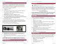
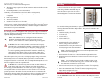
ExtendAir® eMIMO™ Digital Microwave Radios Connections Ensure that power and grounding are properly wired and installed before making additional connections. The included grounding hardware allows connection of a grounding lug to the M5 receptacle near the lower-left corner of the radio. Place the wave washer next to the head of the screw. Place flat washers on both sides of the grounding lug. Another grounding connection is available on the power injector. After establishing the radio link, connect the Ethernet services matching configurations made in the Exalt GUI. Use a ping test to verify connectivity across Ethernet. ExtendAir® eMIMO™ Indicators The PoE/ETH1 connector inside the radios have LEDs to indicate status: The bottom LED is solid green when power is properly applied. The top LED is solid when an Ethernet link is established, and blinks when Ethernet traffic is present. Digital Microwave Radios Quick Start Guide Register the Product Products registered within 90 days of purchase receive 2 full years of warranty coverage for no extra charge. Unregistered products and products registered after the 90-day period, only receive a 1-year warranty. Register the product according to the instructions on the provided registration card. See the I&M Guide for the full warranty statement. For More Information Refer to the I&M Guide, which can be downloaded from the radio or from the Internet at: http://login.exaltcom.com New users must register before logging into the support section of the Exalt website. For post-sales support, contact Exalt Customer Care at: Phone: (408) 688-0202 Toll-Free (USA): (877) EXALT-01 (392-5801) Support email: [email protected] Live support is provided from 7am to 4pm Pacific, Monday through Friday except designated holidays. Extended-hour support available, sold separately. Sales email: [email protected] Models: r5050 and rc5050 Series Exalt Communications, Inc. 254 E. Hacienda Ave. Campbell, CA 95008 USA (408) 688-0200 Part Number: 208398-002 © 2013 Exalt Communications, Inc. All rights reserved. 2014-01-07 208398-002 11 2014-01-07 ExtendAir® eMIMO™ Digital Microwave Radios ExtendAir® eMIMO™ Digital Microwave Radios Copyright © 2013 by Exalt Communications, Inc. All rights reserved. No part of this document may be reproduced without prior written permission from Exalt. The information in this document is subject to change without notice. Exalt is not liable for errors contained herein or for incidental or consequential damages in connection with the furnishing, performance, or use of this document or equipment supplied with this document. Exalt makes no warranty of any kind with regard to this document. Full Warranty information is in the Installation & Management manual. Exalt and the Exalt logo are copyrights of Exalt Communications, Inc. ExtendAir is a registered copyright of Exalt Communications Inc. All other names are trademarks of their respective owners. The system has been tested and found to comply with the limits of a class B digital device, pursuant to Part 15 of the FCC Rules. These limits are designed to provide reasonable protection against harmful interference in a residential installation. This equipment generates uses and can radiate radio frequency energy and, if not installed and used in accordance with the instructions, may cause harmful interference to radio communications. However, there is no guarantee that interference will not occur in a particular installation. If this equipment does cause harmful interference to radio or television reception, which can be determined by turning the equipment off and on, the user is encouraged to try to correct the interference by one of more of the following measures: Reorient or relocate the receiving antenna. Increase the separation between the equipment and receiver. Connect the equipment into an outlet on a circuit different from that to which the receiver is connected. Consult the dealer or an experienced radio/TV technician for help. Shielded cables and I/O cords must be used for this equipment to comply with the relevant FCC regulations. Changes or modifications not expressly approved in writing by Exalt may void the user’s authority to operate this equipment. This Class B Digital apparatus meets all the requirements of the Canadian InterferenceCausing Equipment Regulations. Cet appareil numerique de la classe B respecte les exigensces du Reglement sur le material broilleur du Canada. this device may not cause interference, and this device must accept any interference, including interference that may cause undesired operation of the device. Antennae associated with these devices must be mounted in a restricted area, at a designated minimum distance away from humans who may be subject to long-term or continuous exposure. Refer to the Installation & Management Guide (I&M) for details. Antennas are typically aligned using the internal alignment buzzer and the RSL value reported on the radio GUI. THIS PRODUCT MUST BE PROFESSIONALLY INSTALLED Contact Exalt or refer to the Installation & Management Guide for a list of supported antennas and regional transmitter power requirements. 1. 2. 3. Configure one side of the link as Radio A and the other side as Radio B, with the desired link frequency and Bandwidth setting at both ends, and the maximum transmit power allowed. Enable Radio A with the Radio (RF) State parameter enabled on the System Configuration page. Enable Radio B and enter the RF MAC Address of Radio A on the Antenna Alignment page of the GUI. The RF MAC Address of each radio is located on the Radio Information page. 4. 5. Coarse align antennas at both ends using compass bearings and/or a local landmark on the path. Click Start Alignment on Radio B. The alignment buzzer sounds. When the alignment buzzer is enabled, the radio enclosure emits a sound. The beeps get more rapid as better levels of RSL are achieved. Align the antennas until the fastest beeps are accomplished. The beep interval is once per 3 seconds if the far-end RF MAC Address is not found. Once the far-end is acquired, the beep interval starts at one beep per second and once the far-end is acquired, becomes a more rapid beep from –95 to –53 dBm. Above –53 dBm, the beep is continuous. 6. Adjust the azimuth and elevation of the Radio B antenna until it aligned and has the best possible RSL. RSL (RSSI) is reported on the Antenna Alignment page, to the right of the MAC Address entry. 7. 8. 9. Lightly tighten the antenna adjustment mechanics. After Radio B is aligned as best as possible, enable alignment on the Radio A side, enable Access List Filtering and enter the far-end RF MAC Address. Repeat this procedure to align Radio A. Alignment should be optimized at both ends, one side at a time, back and forth, until the target RSL is achieved, as indicated on the radio GUI Performance page. 10. After the designed RSL is achieved, mechanically secure the antenna for azimuth and elevation alignment. Carefully monitor the RSL level while tightening the mechanics, and ensure that the antenna remains in alignment. 11. Disable Antenna Alignment on both ends of the link once alignment is completed. 208398-002 1 2014-01-07 208398-002 10 2014-01-07 ExtendAir® eMIMO™ Digital Microwave Radios ExtendAir® eMIMO™ Digital Microwave Radios Cabling Introduction Lightning arrestors are recommended near the radio for surge protection on all cabled interfaces. Use lightning arrestors on all cable egress points (where cables enter shelters or buildings) to protect against harm to humans and/or equipment collocated in the shelter or building. For the RF connection on rc models, the following devices are approved: Polyphaser AL-LSXM Citel PRC5800 For the PoE connection, any 802.3af or 802.3at rated surge suppression device supporting 1000BaseT (GbE) can be used. For the ETH2 and ETH3 connections, any 100BaseT rated surge suppression device can be used. Maintain waterproof spacers on unused connectors. Use UV-rated (outdoor) CAT5e or CAT6 cable, for all connections. The outside radius cables entering the radio ports must be between 0.25 and 0.31 inches to ensure a water-tight connection. To connect the port connector: 1. Place connector parts on the cable as shown in the following photos. All connector parts can be placed on a terminated cable. The screw cap and beveled washer both allow the RJ-45 connector to pass through, and the rubber seal has a split slot to fit over the cable insulation. 2. Insert the RJ-45 connector until it clicks into place. 3. 4. Adjust the position of the rubber seal into the connector recepticle. Align the beveled washer on top of the rubber seal, and strongly handtighten the rear section of the connector. 5. Inspect the rubber seal to ensure that there is no deformation and it appears tight. The total length of the PoE cable, including the cable from the power injector to the connected network equipment must not exceed 100 meters. Note: Read this entire document before attempting to install Exalt digital microwave radios. The reader is strongly encouraged to obtain a copy of the Installation and Management Guide (I&M) for this product. The I&M is embedded in the radio’s graphical user interface (GUI) and can be saved locally (as described in this document). In addition, customers may request access to documentation (and software) by creating an account and logging in at: http://login.exaltcom.com This quick start guide (QSG) is intended to provide only a brief overview of the ExtendAir eMIMO radios. The reader must have experience with networking and RF. Refer to the I&M for full descriptions, regulatory requirements, safety requirements and troubleshooting information. Preparation Complete a path analysis and link design prior to installation. Gather the following information in the design phase: Length(s) and type(s) of transmission system cabling and connectors (if any) Make and model of antennas Antenna structure requirements, antenna and radio mounting locations Cable routes and egress location Grounding plan, surge protection, grounding mechanics, power and wiring Critical radio settings: RF center frequency, transmitter output power, occupied channel bandwidth, and link distance setting Anticipated RSL Perform the following tasks before installing the radio terminals: Build antenna/radio structures and egress mechanics Mount antennas and transmission line (if any), lightning arrestor(s), and grounding Prepare and test interface and power cables Shipping Contents Antennas must be installed at both ends of the planned link to commence precision alignment. Refer to the Exalt white paper, Antenna Alignment. Review the labeling and contents of all boxes and the physical condition of the shipping container and contents. Ensure that items are not damaged, and that part numbers and serial numbers match the original equipment order and shipping information. Each radio terminal box should contain the following: Radio terminal (configured as Radio B) Mounting kit (for pole mounting) Accessory kit Quick start guide (this document) Product registration card 208398-002 208398-002 Aligning Antennas 9 2014-01-07 2 2014-01-07 ExtendAir® eMIMO™ Digital Microwave Radios ExtendAir® eMIMO™ Digital Microwave Radios The accessory kit contains the following items: Weather-seal tape (required for the RF connectors and coaxial cables on the rc models) Grounding hardware (screws and washers) Generally, a link installation requires items that are sold separately: Power-over-Ethernet (PoE) Injector (802.3af compliant or 802.3at compatible) PoE surge protectors Antenna (rc models) Outdoor-rated CAT5e or CAT6 cable. For Ethernet connections, a maximum length of 100m applies to total length of cable between the radio terminal and the first network-aware connection, such as a switch or router. For the PoE connection, it should be straight wired Ethernet between the PoE injector and the radio. Mounting Getting Started It is strongly advised to configure the radio system prior to physical installation. This step minimizes total installation time and aids troubleshooting that may be required during commissioning. Note: Exalt eMIMO radios are configured with the transmitters disabled at manufacture. Radios can be powered-up on receipt. However, if the transmitter is enabled, the following caution applies. CAUTION: For the rc models, the RF connection must be properly terminated into a 50-Ohm load (termination or attenuator) at all times. If this is not performed, the radio may be damaged by simply applying power if the transmitter is enabled. Also, there are human safety factors to consider regarding potentially harmful RF radiation. Alternatively, cable the port to the antenna system or back-to-back with the other terminal with at least 60dB of total attenuation between the terminals. The radio requires a DC power source with proper output voltage and currenthandling capacity, in accordance with the radio specifications. The DC power is delivered by a Power-over-Ethernet (PoE) injector that is connected with a straight-wired CAT5e or CAT6 cable. This is accomplished through the use of a 802.3af compliant or 802.3at compatible PoE. CAUTION: It is critical that only 802.3af or 802.3at PoE solutions are used with the radio. Do not mix solutions from other Exalt products. As shown in the figure at the right, rc models mount using a flat plate and band clamps to secure the unit to the pole. No elevation or azimuth adjustment is required as adjustment is made using the antenna mechanics. For r models with integrated antennas, to pole mount the unit, reference the following illustration and follow the procedure. These parts are included in the mounting kit: 1. 2. 3. 4. 5. Bracket assembly ( and ) 2 U-bolts () 4 Lock nuts () 4 Flat washers () 8 Hex head screws () Attach bracket to the radio body as shown, using four hex head screws. Attach bracket to the pole with the two U-bolts,using the lock nuts and washers. Note: Keep the lock nuts slightly loose for lateral adjustment of the bracket before final tightening. Position bracket relative to the desired antenna height and elevation. Partially insert two hex head screws in the lower screw holes of the pole bracket . Note: Leave enough of the screw heads extending so that you can slide bracket over them, allowing you to pivot the radio and align the slotted holes with the upper screw holes. Insert two hex head screws in the upper holes of bracket to temporarily secure the radio before making final adjustments. Once the units at both ends of the link are mounted, align and properly adjust them, and tighten all screws. It is strongly recommended that the AC mains supply or DC supply be fused or on a separate breaker to ensure against over-voltage and/or over-current and provide protection to the radio electronics and other devices connected to the same supply. Because mains power supplies are subject to significant spikes or variation, power conditioning is recommended. An Uninterruptible Power 6. 208398-002 208398-002 3 2014-01-07 Extracting the I&M Guide Click the Manual navigation link. The browser displays the PDF file. Click the Save button in the PDF toolbar to save the manual on the local system. 8 2014-01-07 ExtendAir® eMIMO™ Digital Microwave Radios ExtendAir® eMIMO™ Digital Microwave Radios Note: On a reboot of the radio under management, the radio drops traffic across the link. The far-end (remote) radio is inaccessible for approximately 2 minutes. To reset the radio to factory settings: 1. Remove the waterproof connector/gland/spacer assembly from the Sync In/Out port of the radio. Keep all pieces of this connector safe and secure (rubber gland, beveled washer, nut, spacer plug). If the Sync port was in use, remove the connected sync cable. 2. 3. Place the reset tool (an RJ-45 wired with pins 3 and 5 connected to each other and no other pins connected) into the Sync In/Out port of the radio. If already communicating to the radio GUI, navigate to the Shutdown page and click the Shutdown button Wait for 30 seconds before going on to the next step. 4. Power cycle the radio using one of the following methods: Remove power at the PoE injector source Disconnect from the PoE injector or disconnect at the ETH1/PoE port 5. Reconnect or reapply power. IMPORTANT! Ensure that proper and constant power is applied for the remainder of this procedure. Wait approximately 20 seconds or until three short beeps occur. Note: On any wait longer than 20 seconds, at approximately every 10 seconds thereafter, two short beeps sound. 6. Remove the reset tool from the Sync In/Out port. Wait approximately 45 to 90 seconds or until one long beep occurs. 7. Replace the waterproof connector/gland/spacer assembly in the Sync In/Out port or reconnect sync cable and tighten the connector assembly. Wait approximately two minutes. The following changes are made to the radio: IP address = 10.0.0.1 IP Mask = 255.255.255.0 Admin and User passwords = password All factory settings restored The radio should be accessible using the above default access configurations and can be reprogrammed for all other parameters. 208398-002 7 2014-01-07 Source (UPS) or other form of battery-backed system protects against brownout and black-out conditions, and condition the power presented to the adapter. 1. Connect the straight-wired outdoor rated CAT5e or CAT6 cable to the PoE/ETH1 connection on the radio side, and then to the DATA+POWER or OUTPUT port connection of the power injector. 2. Connect the network Ethernet connection to the DATA or INPUT port connection of the power injector. 3. Mount and ground the PoE injector, as necessary. 4. Apply appropriate AC or DC power (with proper current rating) to the input connector of the power injector. Note: In the GUI, press the Shutdown button before removing power from the radio. This preserves the settings in radio memory. Configuration Overview It is strongly advised to configure the radio system prior to physical installation. This step minimizes total installation time and aids troubleshooting that may be required during commissioning. For proper communication, one radio terminal must be configured as Radio A (radios are configured as Radio B at manufacture). Other configurations are required before installation is complete. Use the Exalt browser-based GUI for configuration. Connect a CAT5e or CAT6 cable to the DATA connector on the power injector using either a straight or crossover cable meant for Ethernet connections. Connect the opposite end of this cable to the management computer’s Ethernet port. Use a browser to launch the Exalt GUI on the radio. The computer accessing the Exalt GUI must match the IP subnet of the radio. The radio’s default IP address is 10.0.0.1. Since all radios are configured with the same IP address at manufacture, change at least one radio’s IP address to avoid an IP address conflict. Use the following procedure: 1. Change the IP address of the accessing computer to match the radio’s subnet. 2. Select the Ethernet network adapter, and then select TCP/IP properties. 3. Select the static IP address option and change the IP address to 10.0.0.x (where x does not equal 1 or any other address planned for either radio). Using the GUI A browser is required to access the GUI. Microsoft Internet Explorer 5.0 or greater is recommended (IE 10 and above may require setting compatibility 208398-002 4 2014-01-07 ExtendAir® eMIMO™ Digital Microwave Radios ExtendAir® eMIMO™ Digital Microwave Radios mode to IE 9). Firefox, Chrome and Safari are also supported. Use the following procedure to access the Exalt GUI. 1. Open a browser window and type the IP address of the radio (for example, 10.0.0.1) in the address field, and press ENTER. Repeat the above steps for Radio A, except for the following: A password dialog box displays. 2. 3. 4. Note: If the IP address or License Key was changed, the browser session is lost. If you changed the IP address, log in with the new IP address and confirm the configuration. Type admin into the User name field. Type password into the Password field. Press Login. Access List Filtering is recommended for Radio A. The GUI displays the Radio Information page. Use the navigation panel on left side of the window to access the configuration and management tools. To establish a working link: 1. For the first radio–Radio B–log in to the GUI. 2. From the Radio Information page, copy and paste the RF MAC Address into a text file, in the form aa:bb:cc:dd:ee:ff. 3. On the System Configuration page, enter the following parameters for your installation in the New Value column: 4. 5. RF Frequency (if not known select AUTO) Effective Antenna Gain (rc models only)–The sum of the antenna gain and all cable/connector losses between the radio and antenna. Link Distance–It is critical to set this to a value equal to or greater than the actual link distance. Note: If the radio is connected to an antenna or proper attenuation/load, you can now enable the Radio (RF) State. Click Update and wait for confirmation that the changes are committed. Go to Administration Settings and enter your parameters in the New Value column: 6. Frequency Band Bandwidth Transmit Power Limit–This parameter is normally disabled. If a value of less than the desired maximum, enable the limit and select the desired output power level. Link Security Key (required) Default Gateway (required) Encryption (if required; you must also enter the encryption key) IP Address–At least one radio must have a different address than 10.0.0.1. License Key (if ordered)– License keys are S/N specific. For step 2: Add the RF MAC Address of Radio A to your record. For step 3: In addition to all other items, change the radio to Radio A. For step 4: If Access List Filtering has been enabled, enter the Radio B RF MAC Address (from the text file you created) in the Peer MAC Address field. 7. On Radio A, go to Configuration>Advanced>Antenna Alignment and enter the Radio B RF MAC Address in the Remote MAC Address field. 8. Log in to Radio B and go to Administration>Settings and enter the RF MAC Address for Radio A (from your text file) in the Peer MAC Address field. 9. On Radio B, go to Configuration>Advanced>Antenna Alignment and enter the RF MAC Address for Radio A in the Remote MAC Address field. Note: Ensure that the Firmware Version (on the Radio Information page) matches for both terminals in the link. Follow the instructions in the I&M to upgrade firmware. It is advised to upgrade radios to the latest firmware, which is obtained on the Exalt website. At this stage, if and when the Radio (RF) State for both radios is enabled on the System Configuration page, the link is ready for back-to-back testing or installation. This product must be professionally installed. The Transmit Power level must be configured, prior to connection to the antenna system, in accordance to all government regulations that apply. The professional installer is responsible to ensure that the implementation is within legal limits. Exalt strongly recommends a proper back-to-back test, because it can be extremely challenging, time consuming, and costly to troubleshoot a system that is not properly preconfigured and tested. A back-to-back test requires two RF cables, and approximately 60–70dB of attenuation between the radios, using RF absorption material for integrated antenna models or coaxial attenuators on both RF connections for rc models. Reset to Factory Settings If the IP address or password is lost or forgotten or any issue exists where access to the radio cannot be made, reset the radio to factory defaults. Click Update and wait for confirmation that changes are committed. 208398-002 5 2014-01-07 208398-002 6 2014-01-07