1
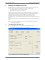
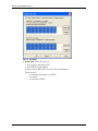
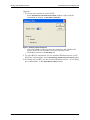
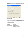
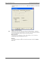
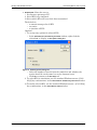
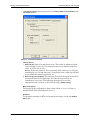
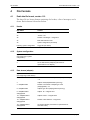
Data Reconstructor Software Manual 311 Meacham Avenue Elmont NY 11003 Tel. (516) 327-0000 Fax (516) 327-4645 e-mail: [email protected] website: www.mil-1553.com Table of Contents 1 Introduction . . . . . . . . . . . . . . . . . . . . . . . . . . . . . . . . . . . . . . . . . . . . 1 2 Overview . . . . . . . . . . . . . . . . . . . . . . . . . . . . . . . . . . . . . . . . . . . . . . . 1 2.1 Data Reconstruction from a Replay or Log File . . . . . . . . . . . . . . . . . . . . . . 1 2.2 Retries . . . . . . . . . . . . . . . . . . . . . . . . . . . . . . . . . . . . . . . . . . . . . . . . . . . . . . . 2 3 Working with DataReconstructor . . . . . . . . . . . . . . . . . . . . . . . . . . . 3 3.1 Transmitting Exalt Data Replay Files . . . . . . . . . . . . . . . . . . . . . . . . . . . . . . 3 3.2 Transmitting Merlin+ Data Log Files . . . . . . . . . . . . . . . . . . . . . . . . . . . . . . 11 4 File Formats . . . . . . . . . . . . . . . . . . . . . . . . . . . . . . . . . . . . . . . . . . . 17 4.1 Exalt data file format, version 1.10 . . . . . . . . . . . . . . . . . . . . . . . . . . . . . . . 4.1.1 Header . . . . . . . . . . . . . . . . . . . . . . . . . . . . . . . . . . . . . . . . . . . . . . . . . . . . . 4.1.2 System configuration . . . . . . . . . . . . . . . . . . . . . . . . . . . . . . . . . . . . . . . . . . 4.1.3 Data stream (adapter) . . . . . . . . . . . . . . . . . . . . . . . . . . . . . . . . . . . . . . . . . 4.1.4 Trigger list . . . . . . . . . . . . . . . . . . . . . . . . . . . . . . . . . . . . . . . . . . . . . . . . . . 4.1.5 Messages. . . . . . . . . . . . . . . . . . . . . . . . . . . . . . . . . . . . . . . . . . . . . . . . . . . 4.1.6 Footer. . . . . . . . . . . . . . . . . . . . . . . . . . . . . . . . . . . . . . . . . . . . . . . . . . . . . . 4.1.7 Gap List . . . . . . . . . . . . . . . . . . . . . . . . . . . . . . . . . . . . . . . . . . . . . . . . . . . . 4.1.8 Mark list . . . . . . . . . . . . . . . . . . . . . . . . . . . . . . . . . . . . . . . . . . . . . . . . . . . . 4.2 17 17 17 17 18 19 20 20 20 Merlin+ log Files . . . . . . . . . . . . . . . . . . . . . . . . . . . . . . . . . . . . . . . . . . . . . . 21 Figures Exalt Figure 1 Figure 2 Figure 3 Figure 4 Figure 5 Figure 6 Figure 7 Figure 8 Figure 9 DataReconstructor main window: Exalt Data Replay Files . . . . . . . . . . . . . . . . . . . 3 Board and Module for Each Active Channel . . . . . . . . . . . . . . . . . . . . . . . . . . . . . . 4 Exalt – Selecting buses over which to transmit data . . . . . . . . . . . . . . . . . . . . . . . . 4 Map dialog box . . . . . . . . . . . . . . . . . . . . . . . . . . . . . . . . . . . . . . . . . . . . . . . . . . . . 5 Bus Setup . . . . . . . . . . . . . . . . . . . . . . . . . . . . . . . . . . . . . . . . . . . . . . . . . . . . . . . . 6 RT Retry options dialog box . . . . . . . . . . . . . . . . . . . . . . . . . . . . . . . . . . . . . . . . . . 7 Board Setup . . . . . . . . . . . . . . . . . . . . . . . . . . . . . . . . . . . . . . . . . . . . . . . . . . . . . . 8 Transmission Options . . . . . . . . . . . . . . . . . . . . . . . . . . . . . . . . . . . . . . . . . . . . . . . 9 Display Options . . . . . . . . . . . . . . . . . . . . . . . . . . . . . . . . . . . . . . . . . . . . . . . . . . . 10 Merlin+ Figure 10 Figure 11 Figure 12 Figure 13 Figure 14 Figure 15 Figure 16 Figure 17 DataReconstructor main window: Merlin+ Data Log Files . . . . . . . . . . . . . . . . . Board and Module for Each Active Channel . . . . . . . . . . . . . . . . . . . . . . . . . . . . Selecting channels over which to transmit data . . . . . . . . . . . . . . . . . . . . . . . . . Bus Setup . . . . . . . . . . . . . . . . . . . . . . . . . . . . . . . . . . . . . . . . . . . . . . . . . . . . . . RT Retry options dialog box . . . . . . . . . . . . . . . . . . . . . . . . . . . . . . . . . . . . . . . . Board Setup . . . . . . . . . . . . . . . . . . . . . . . . . . . . . . . . . . . . . . . . . . . . . . . . . . . . Transmission Options . . . . . . . . . . . . . . . . . . . . . . . . . . . . . . . . . . . . . . . . . . . . . Display options . . . . . . . . . . . . . . . . . . . . . . . . . . . . . . . . . . . . . . . . . . . . . . . . . . Data Reconstructor Software Manual 11 11 12 12 13 14 15 16 page i page ii Excalibur Systems Introduction 1 Data Reconstruction from a Replay or Log File Introduction DataReconstructor reads replay files created by Exalt and log files created by Merlin+. It reconstructs the data on the 1553 bus using the Excalibur board and Galahad Software Tools. In addition there is a simultaneous monitoring and log file creation feature which enables the program to monitor the data transmitted on the 1553 bus during the reconstruction and retransmission of the data from the log file. The DataReconstructor also includes the standard 1553 ‘retries’ feature. If a message does not get a response from the RT, or gets a bad response, it tries again. Important DataReconstructor now uses the EXC-1553PCI/Px’s and the M4K1553Px’s Internal Concurrent Monitor. The program does not require a separate channel/module. This software is for use in a lab environment, to reconstruct a situation recorded inflight or to do regression testing. 2 Overview DataReconstructor supports the Excalibur 1553 PCI/Px boards and the M4K1553Px module on the EXC-4000PCI carrier board. Data may be reconstructed with a single Px channel or module. However, for monitoring data, the user must have a board or module with an internal Concurrent Monitor [-PMx]. The data file format is the same as the log files written either by Exalt or Merlin+. See Section 4: File Formats on page17. 2.1 Data Reconstruction from a Replay or Log File The program reads replay files created by Exalt or a log files created by Merlin+, and reconstructs the data on the 1553 bus using the Excalibur board and Galahad Software Tools. The user selects a file and “runs” it. DataReconstructor reconstructs and transmits the same data on the 1553 bus, so that if Exalt or Merlin+ were again monitoring they will create the same file. There may be some differences in the actual transmission, depending which RT options and which transmission options were selected. The data transmission will be synchronized based on the Time tags of the messages in the file – messages are sent out according to their Time tags. See Transmission Options on page 9 for Exalt files or page 15 for Merlin+ files. In addition the user defines for each RT: • the retry options • to simulate or not • to enable (have its data transmitted on the 1553 bus) or to disable (so that messages in the file relevant to this RT are not transmitted) For more details see RT Setup options on page 6 for Exalt files or page 13 for Merlin+ files. Data Reconstructor Software Manual page 1 Overview 2.2 Retries This is a standard 1553 feature and is supported by Excalibur boards. If a message does not get a response from the RT, or gets a bad response, the message is sent again. The user selects the number of retries (between 0 and 3). When the BC gets a bad response from the RT, it will resend the message between 0 and 3 times, as selected by the user, on the same or alternate bus. See RT Setup options on page 6 for Exalt files or page 13 for Merlin+ files. page 2 Excalibur Systems Working with DataReconstructor 3 Transmitting Exalt Data Replay Files Working with DataReconstructor DataReconstructor reads Exalt replay files and Merlin+ log files. Each 1553 bus used by DataReconstructor is assigned to a channel. In both modes: • • up to 8 channels can be active simultaneously the default is for channel 0 to be selected In Exalt the data source is from the one input file and recorded to one output file, regardless of the number of active channels. Therefore, before transmitting data, each named module in the file must be mapped to a specified channel. In Merlin+ the data source and output is per channel. Therefore, before transmitting data, separate input and output files must be specified for each active channel. Follow the setup procedure for either Exalt or Merlin+ before beginning to transmit data. Note: 3.1 For ease of use, DataReconstructor uses the standard Windows keyboard conventions and shortcuts. Transmitting Exalt Data Replay Files To set up DataReconstructor to transmit data from Exalt replay files: 1. Run DataReconstructor, to display the main window. Figure 1 DataReconstructor main window: Exalt Data Replay Files Data Reconstructor Software Manual page 3 Working with DataReconstructor Note: The carrier board and module for each channel which has been set up to transmit data, is displayed on the channel tab page. Figure 2 Board and Module for Each Active Channel 2. 3. Select Exalt from the File mode dialog box, if it is not already selected. From the Active channels dialog box, check the channels over which to transmit data. For each channel selected, a corresponding Channel tab is then available for setting up RTs, selecting the Excalibur board, choosing transmission and display options. Figure 3 Exalt – Selecting buses over which to transmit data 4. 5. 6. page 4 To send out messages in a loop, check Continuous replay. The file runs continuously until the user clicks Stop. Select an Exalt *.rpf input file. To run a different *.rpf file, click Change. Browse for the file. Click Map, to display the Map dialog box. Excalibur Systems Working with DataReconstructor Transmitting Exalt Data Replay Files Figure 4 Map dialog box To map a named module: a. Highlight a module name from the Module names window. b. Select a channel from the Channels combo box After mapping all the named modules, click OK. Note: Only mapped module names will have their messages transmitted. A named module may be mapped to an inactive channel, reserving the channel for transmitting a different reconstruction of the data file. 7. If at least one channel will be concurrently monitored, select an Exalt *.rpf output file. Click Change to select an output file. For each channel activated in the Active Channels dialog box, set up the RTs, select the Board Setup, Transmission and Display options. 8. Click the Channel tab and then Setup, to display the Setup dialog box. Data Reconstructor Software Manual page 5 Working with DataReconstructor Figure 5 Bus Setup a. RT Setup tab allows the user to: i Set up retry options per RT ii Select RTs for simulation iii Select which RTs will have their data transmitted The default is: • to transmit messages for all RTs • no retries • to simulate all RTs page 6 Excalibur Systems Working with DataReconstructor Transmitting Exalt Data Replay Files Optional i To set up retry options for selected RTs: • In the Select RTs for simulation by the board window; right-click the selected RT, to display an RT Options dialog box. Figure 6 RT Retry options dialog box • Select the number of retries from the combo box and whether the retries should be on the same bus or the alternate buses. • Click OK, to return to the RT setup tab. ii To select RTs for simulation, use the standard Windows mouse +[Ctrl/ Shift] key combinations, in the Select RTs for simulation by the board window. iii To enable selected RTs, use the standard Windows mouse + [Ctrl/Shift] key combinations, in the Select RTs to enable window. Data Reconstructor Software Manual page 7 Working with DataReconstructor b. Board Setup allows the user to select the board type, device number and module number. Figure 7 Board Setup Note: page 8 For the EXC-1553PCI/Px leave the Default Device Number setting. For the EXC-4000PCI: • If there is only one board present, leave the Default Device Number setting. • If you have more than one EXC-4000PCI board, for each board, enter the Device Number selected in the ExcConfig utility program. In addition the user may also: Select: To: Monitor the bus during data reconstruction Enable concurrent monitoring and create a new file Synchronize with external clock Enable synchronization with an external clock source. For more details see the hardware User’s Manual. Excalibur Systems Working with DataReconstructor Transmitting Exalt Data Replay Files c. Transmission Options allows the user to set Mode code subaddress and Broadcast options. Figure 8 Transmission Options Note: In Exalt mode the base Time tag is always the first message – messages always start going out immediately at zero time. The following messages go out at the appropriate times relative to the first message. Mode Code Options The board can be configured to allow either 00000 or 11111 or both, as possible Mode Code subaddresses (0 or 31). Broadcast To interpret messages to RT31 as broadcast messages, check the Enabled box. (RT 31) Data Reconstructor Software Manual page 9 Working with DataReconstructor d. Display Options, Number of messages transmitted and Time tag, if checked, are displayed and periodically updated as data is transmitted, in the DataReconstructor main screen. Figure 9 Display Options 9. 10. 11. 12. page 10 Click OK, to return to the DataReconstructor main window. Click Save Settings, to save the current settings. These are the settings which will be available the next time DataReconstructor is opened. Click Transmit, to start transmitting the data from the replay file. The Number of messages transmitted and Time tag are updated periodically, for the currently displayed channel, if these options were set in the Setup | Display options dialog box. See Figure 1: DataReconstructor main window: Exalt Data Replay Files on page 3. Click Stop, to stop transmission. Excalibur Systems Working with DataReconstructor 3.2 Transmitting Merlin+ Data Log Files Transmitting Merlin+ Data Log Files To set up DataReconstructor to transmit data from Merlin+ log files: 1. Run DataReconstructor, to display the main window. Figure 10 DataReconstructor main window: Merlin+ Data Log Files Note: The carrier board and module for each channel which transmit data, is displayed on the channel tab page. Figure 11 2. has been set up to Board and Module for Each Active Channel Select Merlin from the File mode dialog box, if it is not already selected. Data Reconstructor Software Manual page 11 Working with DataReconstructor 3. From the Active channels dialog box, check the channels over which to transmit data. For each channel selected, a corresponding Channel tab is then available for setting up RTs, selecting the Excalibur board, choosing transmission and display options. Figure 12 4. 5. 6. 7. Selecting channels over which to transmit data To send out messages in a loop, check Continuous replay. The file runs continuously until the user clicks Stop. For each channel activated in the Active channels dialog box: Select a Merlin+ *.dmp input file. To run a different *.dmp file, click Change. Browse for the file. Select a Merlin+ *.dmp output file. Click Change to select an output file. Set up the RTs, select the Board Setup, Transmission and Display options. Click the Channel tab and then Setup, to display the Setup dialog box. Figure 13 page 12 Bus Setup Excalibur Systems Working with DataReconstructor Transmitting Merlin+ Data Log Files a. RT Setup tab allows the user to: i Set up retry options per RT ii Select RTs to be simulated iii Select which RTs will have their data transmitted The default is: • to transit messages for all RTs • no retries • to simulate all RTs Optional i To set up retry options for selected RTs: • In the Select RTs for simulation by the board window; right-click the selected RT, to display an RT Options dialog box. Figure 14 RT Retry options dialog box • Select the number of retries from the combo box and whether the retries should be on the same bus or the alternate buses. • Click OK, to return to the RT setup tab. ii To select RTs for simulation, use the standard Windows mouse +[Ctrl/ Shift] key combinations, in the Select RTs for simulation by the board window. iii To enable selected RTs, use the standard Windows mouse + [Ctrl/Shift] key combinations, in the Select RTs to enable window. Data Reconstructor Software Manual page 13 Working with DataReconstructor b. Board Setup allows the user to select the board type, device number and module number. Figure 15 Note: page 14 Board Setup For the EXC-1553PCI/Px leave the Default Device Number setting. For the EXC-4000PCI: • If there is only one board present, leave the Default Device Number setting. • If you have more than one EXC-4000PCI board, for each board, enter the Device Number selected in the ExcConfig utility program. In addition the user may also: Select: To: Monitor the bus during data reconstruction Enable concurrent monitoring and create a new file Synchronize with external clock Enable synchronization with an external clock source. For more details see the hardware User’s Manual. Excalibur Systems Working with DataReconstructor Transmitting Merlin+ Data Log Files c. Transmission Options allows the user to set Time tag, Mode code subaddress and Broadcast options. Figure 16 Transmission Options Time tag options i Base time tag: Enter a hexadecimal value. This value is subtracted from every message’s time tag. If a message’s time tag is smaller than this value, it will be set to zero. Example: If the user enters 9, then a message with time tag 5 is sent out immediately, as if it had time tag 0. A message with a time tag 0×B will go out when the time tag reaches 2, etc. ii Base time tag = first message: The time tag of the first message in the file is subtracted from all the time tags. The first message will go out immediately, zero time. The following messages go out at the appropriate times relative to the first message. [Default setting] Mode Code Options The board can be configured to allow either 00000 or 11111 or both, as possible Mode Code subaddresses (0 or 31). Broadcast To interpret messages to RT31 as broadcast messages, check the Enabled box. (RT 31) Data Reconstructor Software Manual page 15 Working with DataReconstructor d. Display Options, Number of messages and Time tags, if checked, are displayed and periodically updated as data is transmitted, in the DataReconstructor main screen. Figure 17 8. 9. page 16 Display options 10. Click OK, to return to the DataReconstructor main window. Click Save Settings, to save the current settings. These are the settings which will be available the next time DataReconstructor is opened. Click Transmit, to start transmitting the data from the replay file. The Number of messages transmitted and Time tag are updated periodically if these options were set in the Setup | Display options dialog box. See Figure 10: DataReconstructor main window: Merlin+ Data Log Files on page 11. 11. Click Stop, to stop transmission. Excalibur Systems File Formats Exalt data file format, version 1.10 4 File Formats 4.1 Exalt data file format, version 1.10 The data file is a binary format consisting of a header, a list of messages, and a footer. Each element is described below. 4.1.1 4.1.2 4.1.3 Header Byte Offset Content 0 “XCAL Replay file” + 9 periods 26 “Version 1.10” 38 Number of messages – unsigned int 42 Base date and time of file 46 System configuration (see below) Following system configuration Trigger list (see below) System configuration Byte Offset (from beginning of system configuration) Content 0 Number of data streams – unsigned int 4 List of data streams (adapters) (see below for representation of an adapter) Data stream (adapter) Byte offset (from beginning of data stream) Content 0 Number of characters in adapter name (adapNameSize) – int 4 Adapter name(adapNameSize bytes long) 4 + adapNameSize Number of characters in adapter type name (adapTypeSize) – int 8 + adapNameSize Adapter type name (adapTypeSize bytes long) 8 + adapNameSize + adapTypeSize Adapter ID – unsigned short 10 + adapNameSize + adapTypeSize Adapter version – unsigned short 12 + adapNameSize + adapTypeSize Number of filter statuses – unsigned int 16 + adapNameSize + adapTypeSize List of filter statuses (see below for representation of each filter status) Data Reconstructor Software Manual page 17 File Formats 4.1.3.1 4.1.4 Filter Status Byte offset (from beginning of filter status) Content 0 Number of characters in full path (fullPathSize) – int 4 Full path (fullPathSize bytes long) 4 + fullPathSize Status -- unsigned char (read as a bit field – bit one indicates that this element is filtered out, bit 2 indicates that this element is inactive) Trigger list This is a list of the triggers (conditions for starting/stopping recording) that were defined when this file was recorded. 4.1.4.1 page 18 Byte offset (from beginning of Trigger List) Content 0 Number of triggers – int 4 List of triggers (see below for representation of each trigger) Trigger Byte offset (from beginning of trigger) Content 0 Number of characters in expression string (expSize) – int 4 Expression string (expSize bytes long) (eg. EU1 + EU2 < 100) 4 + expSize Type – enum (4 bytes) (0 = start trigger. 1 = start/stop trigger, 2 = stop trigger) 8 + expSize Has been set – bool 9 + expSize Is continuous – bool 10 + expSize Is consecutive – bool 11 + expSize Num required occurrences – int 15 + expSize Max hits – int 19 + expSize Is active – bool 20 + expSize Pre trigger time – 64-bit integer 28 + expSize Post trigger time – 64-bit integer 36 + expSize Number of characters in name string (nameSize) – int 40 + expSize Name (nameSize bytes long) 40 + expSize + nameSize Unique ID – unsigned long Excalibur Systems File Formats 4.1.5 Exalt data file format, version 1.10 Messages List of messages (see below for representation of each message) 4.1.5.1 4.1.5.2 4.1.5.3 Byte offset (from beginning of message) Content 0 Adapter ID (unsigned short) 2 Time tag – 64-bit integer 10 Serial number – unsigned long 14 Message identifier – unsigned long 18 Flags (unsigned short) Bus-type specific information 1553 Bus-type specific information Byte offset (from beginning of message) Content 20 Command word – unsigned short 22 Second command word – unsigned short 24 Status word – unsigned short 26 Second status word – unsigned short 28 Px status – unsigned short 30 Number of bytes of data which follow 34 Data bytes 34 + 2 * numDataBytes 1553 additional flags – unsigned short 429 Bus-type specific information Byte offset (from beginning of message) Content 20 Data – unsigned long 24 Status – unsigned long 28 429 additional flags – unsigned short Multipes Bus-type specific information Byte offset (from beginning of message) Content 20 Number of bytes of data which follow 24 Data bytes Data Reconstructor Software Manual page 19 File Formats 4.1.6 4.1.7 Footer Byte offset (from beginning of footer) Content 0 Gap list immediately following gap list Mark list Gap List This is a list of recording gaps – times during the recording session when recording was turned off or was unsuccessful (for example, if the system was overloaded and could not keep up). 4.1.7.1 4.1.8 Byte offset (from beginning of gap list) Content 0 Number of gaps – unsigned int 4 List of gaps Gap Byte offset (from beginning of gap) Content 0 Time tag before gap – 64-bit integer 8 Serial number before gap – unsigned int 12 Time tag after gap – 64-bit integer 20 Serial number after gap – unsigned int 24 Type – int Mark list The list of points in the file which were labeled as significant points to which one may want to return when analyzing the file – like bookmarks. page 20 Byte offset (from beginning of mark list) Content 0 Number of marks – unsigned int 4 List of marks Excalibur Systems File Formats 4.1.8.1 Merlin+ log Files Mark Byte offset (from beginning of mark) 4.2 Content 0 Time tag – 64-bit integer 8 Serial number – unsigned int 12 Number of characters in name (numNameChars) – int 16 Name (numNameChars characters) 16 + numNameChars Number of characters in description (numDescChars) – int 20 + numNameChars Description (numDescChars characters) Merlin+ log Files The data log files are identical to the data files used by Merlin+. This file format will be both written and read by this program. It is a binary file beginning with 100 16-bit values of data. The first 7 16-bit values contain the ASCII values of 'M' 'E' 'R' 'L' 'I' 'N' '+'. The first 16-bit value after is a version number. The files exported by Merlin+ are version 1; files exported by Data Reconstructor are version 2. In version 2 the "filler value" described below is the next 16-bit value in the header. In version 1 the next header 16-bit value is set to one. The remaining header 16-bit values contain a value of one. After the header, the messages are recorded as follows: • • • • • • Size Spare 16-bit value (set to filler value of 0×69) Message status Time Tag lo Time Tag hi (Up to) 36 Words of actual bus data Data Reconstructor Software Manual page 21 The information contained in this document is believed to be accurate. However, no responsibility is assumed by Excalibur Systems, Inc. for its use and no license or rights are granted by implication or otherwise in connection therewith. Specifications are subject to change without notice. March 2004, Rev A-4