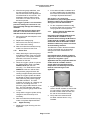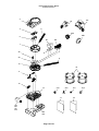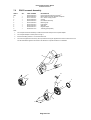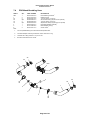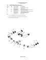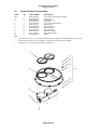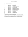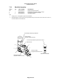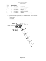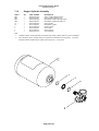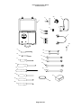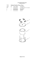
1
BioPak 240R
Closed-Circuit, Self-Contained Breathing Apparatus
Benchman Manual
1437
A47D257 Revision I
B5-06-6000-23-0
April 2012
BioPak 240R Benchman Manual
A47D257 Revision I
WARNINGS
1. INTRODUCTION
1.1
1.2
1.3
1.4
1.5
3
4
Breathable Oxygen
Apparatus Duration
Personnel Training
Servicing
Spare Parts
4
4
4
4
4
2. APPARATUS DESCRIPTION
2.1
2.2
2.3
2.4
2.5
2.6
2.7
2.8
2.9
5
General
Harness
Housing
Breathing Loop
Oxygen Delivery System
Oxygen Cylinder
Alarming System
Facemasks
Optional Attachments
5
5
5
6
6
6
6
7
7
3. TURN AROUND MAINTENANCE PROCEDURE
3.1
3.2
3.3
3.4
3.5
3.6
3.7
3.8
3.9
3.10
3.11
3.12
Maintenance Tag
Disassembly
Cleaning/Disinfection
Coolant Canister
Oxygen Cylinder
Facemask
Assembly
Constant Flow Test
Low Pressure Leak Test
Alarm Test
Upper Housing
Carbon Dioxide Scrubber Pre-Packing Procedure
4. LONG TERM MAINTENANCE PROCEDURE
4.1
4.2
4.3
4.4
4.5
4.6
4.7
4.8
4.9
Visual Inspection
Demand Valve Functional Test
Constant Flow Test
Vent Valve Functional Test
Low Pressure Leak Test
High Pressure Leak Test
Emergency Bypass Valve Functional Test
Alarm Test
Maintenance Tag Validation
5. GENERAL SERVICE PROCEDURES
5.1
5.2
5.3
5.4
5.5
5.6
Scheduled Component Inspection
System Lubrication
Oxygen Cylinder
Alarm Battery Replacement Procedure
Flow Restrictor Replacement Procedure
Factory Service and Training
6. STORAGE GUIDELINES
7. PARTS LISTS
7.1
7.2
7.3
7.4
7.5
7.6
7.7
7.8
7.9
7.10
7.11
7.12
7.13
7.14
7.15
7.16
7.17
8
8
8
8
9
9
9
9
10
10
11
11
11
13
13
13
13
13
13
13
14
14
14
15
15
15
15
15
16
16
17
18
Top Assembly
PRO Facemask Assembly
AV3000 Facemask Assembly
PRO Breathing Hose
AV3000 Breathing Hose
Center Section Lid
Center Section
Diaphragm
Pneumatic Assembly
Manifold Assembly
Alarm Monitor
Oxygen Cylinder
Lower Housing
Service Kit
Coolant Canister Freeze Form
Miscellaneous Supplies
Optional Attachments
8. APPARATUS SPECIFICATIONS
9. MAINTENACE LOG SHEET
18
20
21
22
23
24
25
27
28
30
31
32
33
35
37
38
39
40
41
Page 2 of 41
BioPak 240R Benchman Manual
A47D257 Revision I
WARNINGS
Please Read Carefully and Fully Understand
This manual is for use by personnel trained in the use and care of compressed oxygen,
closed-circuit breathing apparatus, and MUST NOT be used as a self-teaching guide by
untrained users. Failure to understand or adhere to the BioPak user instructions and BioPak
benchman manual may result in injury or death.
Biomarine Inc. has taken great care to ensure that the information in the manual is accurate,
complete and clear. However, Training & Technical Support Services will be pleased to
clarify any points in the manual and answer questions on Biomarine breathing apparatus.
The following warnings are in accordance with certifying authority requirements and
apply to the use of breathing apparatus in general:
•
•
•
•
•
•
•
•
•
•
Breathing apparatus user must be fully trained in the use and care of closedcircuit, self-contained, compressed oxygen breathing apparatus.
Ensure that the selection of the apparatus type is sufficient for the tasks being
undertaken and the hazards likely to be encountered. Please refer to National
Regulations for guidance.
Adequate protection may not be provided in certain highly toxic atmospheres.
The apparatus must be tested and serviced in accordance with the BioPak
240R Benchman Manual.
The quality of oxygen used to supply and charge the breathing apparatus must
be medical or aviation grade oxygen with a moisture content less than 50
mg/m3 at 207 bar.
Ensure that a good seal can be obtained between the face and facemask. The
wearing of beards, side-burns or spectacles may adversely affect the sealing of
a facemask to the wearer’s face.
The apparatus is not designed for use underwater.
The harness must not be used as a vehicle seat or fall arrest restraint.
Replacement of the alarm system battery shall be performed in area
atmospheres known to be safe and non-explosive.
The improper use of closed-circuit breathing apparatus carries a risk of carbon
dioxide poisoning of user. Users shall be fully trained in recognizing the
effects of carbon dioxide poisoning.
DISCLAIMER
Failure to comply with these instructions or misuse of the apparatus may result in:
death, injury or material damage, and invalidate any warranty or insurance claims.
This manual presents the minimum requirements for BioPak utilization.
Page 3 of 41
BioPak 240R Benchman Manual
A47D257 Revision I
1. INTRODUCTION
1.3 Personnel Training
1.1 Breathable Oxygen
Personnel who use closed-circuit, selfcontained, positive-pressure, compressed
oxygen breathing apparatus must be fully
trained in accordance with these
instructions and national regulations.
Oxygen used to supply or charge the
breathing apparatus must be medical or
aviation grade oxygen with a moisture
content less than 50 mg/m3 at 207 bar.
The composition of suitable oxygen is
given below.
These instructions cannot replace an
accredited training course provided by
qualified instructors in the proper and safe
use of Biomarine breathing apparatus.
Oxygen: 99.5% minimum mole
Carbon Dioxide: 300 ppm maximum
Carbon Monoxide: 10 ppm maximum
The purity/quality of oxygen used to supply
and charge breathing apparatus should be
tested periodically in accordance with
national regulations.
National regulations must be observed.
Personnel dealing with compressed
oxygen and compressed oxygen cylinders
must be fully trained in the use and
handling of compressed oxygen.
Please contact Training & Technical
Support Services or your local distributor
for training course details.
Training & Technical Support Services:
Biomarine Inc.
456 Creamery Way
Exton, PA 19341
United States of America
Tel: +1 610.524.8800
Fax: +1 610.524.8807
1.2 Apparatus Duration
Web: BioPak240r.com
The apparatus will provide the user with
440 liters of compressed oxygen and has
been rated for a 4-hour duration based
upon machine testing at a breathing rate
of 30 liters/minute according to
specifications of EN145. Actual duration
of the apparatus will vary to factors such
as:
1.4 Servicing
•
Turn Around Maintenance shall be
performed after each use of the BioPak
240R as detailed in the BioPak 240R
Benchman Manual.
•
•
•
Workload: high work rates will
increase consumption rates of
oxygen.
Facemask Seal: poor seal of
mask will result in system leaks
and high oxygen consumption
rates.
Physical Fitness of Wearer
System Leaks: leaks in the
BioPak system will result in high
oxygen consumption.
The BioPak 240R must be serviced at
scheduled intervals by qualified benchmen
personnel who have completed a formal
training course and hold a current
certificate for the service and repair of
Biomarine breathing apparatus.
Long Term Maintenance must be
performed on a monthly basis, if the
BioPak is in constant use; or, on a
quarterly basis if the BioPak is being used
less than once per month, as defined in
the BioPak 240R Benchman Manual.
It is important that all wearers are aware of
the above factors and take account of
them when assessing BioPak duration.
It is equally important that all wearers
understand that the BioPak 240R
respirator is a positive-pressure apparatus.
Leaks in the apparatus itself or in the seal
between the wearer’s face and the
facemask will lead to the apparatus adding
additional oxygen to maintain positive
pressure.
Benchman training and service contracts
can be provided by contacting Training &
Technical Support Services.
1.5 Spare Parts
Spare parts, accessories, general
information and factory service can be
obtained by contacting Training &
Technical Support Services.
Reference details provided in the BioPak
240R Benchman Manual concerning
spare part identification, accessory
identification and BioPak factory service.
Page 4 of 41
BioPak 240R Benchman Manual
A47D257 Revision I
Equipment with protection level
(EPL) GA
2. APPARATUS DESCRIPTION
2.1 General
BioPak 240R is a closed-circuit, positivepressure, self-contained breathing
apparatus (CCBA) for use in long-duration
missions into atmospheres that are
immediately dangerous to life and health
(IDLH). Applications will include mine
rescue, fire-fighting, confined space entry,
domestic preparedness, military, tunnel
rescue and HAZMAT.
All versions of BioPak 240R feature a
backpack-style housing that is worn over
the shoulders and hips of the wearer. A
pressure gauge is supplied to indicate
remaining stores of oxygen and two visual
alarms and one audible alarm is provided
for system status.
The closed-circuit design will recycle the
wear’s exhalation breath by removing
carbon dioxide, replacing consumed
oxygen, trapping condensation and
cooling the breathing gas.
The positive-pressure design will maintain
internal breathing gas pressures slightly
above external atmospheric pressure.
This feature will provide increased
protection against the inward migration of
external toxins to the wearer.
All external housing components are static
dissipative and flame retardant.
BioPak 240R is approved to the following
European Standards:
•
•
EN 136:1998 Respiratory
protective devices - Full face
masks
EN 145:2000 Respiratory
protective devices – Selfcontained, closed-circuit breathing
apparatus compressed oxygen
type
•
Directive 97/23/EC Pressure
Equipment Directive
•
EN 60079-0:2009/08/01 Electrical
apparatus for explosive gas part 0:
General Requirements
•
EN 60079-11:2007/01/01
Explosive Atmospheres-Part11:
Equipment protection by intrinsic
safety “I”
•
EN 60079-26:2007/03/01
Explosive Atmospheres-Part 26:
•
IEC 60079-0:2007/10/01 Ed:5
Explosive Atmospheres-Part
0:equipment-General
Requirements
•
IEC 60079-11:2006/07/01 Ed:5
Explosive Atmospheres-Part 11:
Equipment protection by intrinsic
safety “I”; CORR 2006/12/08
•
EN 60079-26:2006/08/01 Ed:2
Explosive Atmospheres-Part 26:
Equipment with protection level
(EPL) GA
BioPak 240R is “CE” marked in
accordance with EEC Directive
89/686/EEC.
BioPak 240R Monitor is marked
Ex ia I/IIC T4 Ma/Ga
-20oC <+ Tamb <+ +60oC
NOTIFIED BODIES:
Central Institute for Labour Protection
(Notified Body No. 1437)
Wierzbowa 48
90-133 Lodz, Poland
Intertek Testing & Certification Ltd
Intertek House, Cleeve Road
Leatherhead, Surrey KT22 7SB
United Kingdom
TUV America, Inc.
Industry Service
5 Cherry Hill Drive
Danvers, MA 01923
United States of America
Please contact Biomarine Inc for further
apparatus approval details.
2.2 Harness
The BioPak harness is provided as a
padded harness to increase wearer
comfort. The flame-retardant harness is
manufactured from Kevlar™ and Nomex™
materials with stainless steel hardware.
The harness is attached directly to the
apparatus via locking stainless steel
screws.
2.3 Housing
The backpack-style housing is injection
molded from a flame-retardant
polycarbonate/stainless steel alloy that
provides light weight, high strength and
static dissipation. The housing consists of
a lower portion and an upper portion that
Page 5 of 41
BioPak 240R Benchman Manual
A47D257 Revision I
snaps together in a secure fashion without
the need for connection hardware.
2.4 Breathing Loop
add will provide 80-100 liters/minute of
oxygen flow and is utilized only for
emergency situations.
2.6 Oxygen Cylinder
The oxygen cylinder is a fully wrapped
aluminum carbon fibre composite cylinder
that is secured into the apparatus via
connection to the pressure regulator and a
hold down strap. The cylinder will provide
containment of the oxygen supply at a 207
bar to provide 440 liters of breathable
oxygen to the wearer.
The breathing loop consists of the
breathing chamber, breathing hoses,
facemask connector and facemask.
2.7 Alarming System
The breathing chamber consists of the
center section, center section lid and
diaphragm. The spring loaded diaphragm
will maintain positive pressure within the
apparatus. All oxygen gas additions will
occur within the breathing chamber as well
as over pressure venting. Carbon dioxide
is removed from exhalation gas by the
carbon dioxide scrubbers located within
the breathing chamber. Excessive
moisture will be retained by the moisture
containment sponges located within the
center section. Inhalation breathing gas
cooling will be achieved as the gas travels
around the two coolant canisters of the
breathing chamber.
2.5 Oxygen Delivery System
Oxygen will be delivered from the oxygen
cylinder to the breathing loop through a
pressure regulator and manifold system in
one of three different methods.
Pressure demand oxygen additions are
provided whenever the diaphragm of the
breathing chamber reaches the upper
level of its travel and depresses the
demand valve plunger. Additions will be
made at 80 liters/minutes whenever the
demand valve plunger is depressed.
Pressure demand additions occur
whenever the wearer consumes more
oxygen than is supplied by the constant
add.
Constant add oxygen additions are
continually added to the breathing loop at
an average rate of 1.8 liters/minute. This
oxygen addition rate is equivalent to the
oxygen consumption rate of a wearer at a
moderate work rate.
Emergency add oxygen additions occur
whenever the wearer depresses and holds
the red emergency bypass button. This
The alarming system consists of a
pneumatic pressure gauge and an
electronic monitor to provide the wearer
with independent and redundant system
status indications.
The pressure gauge is mounted on the
harness and retained by a snap strap and
magnet. Remaining stores of oxygen will
be indicated on the gauge and a red band
of color will indicate to the wearer when
oxygen stores have reached 25% of
capacity. The pressure gauge is protected
against sudden loss of oxygen stores in
the event of gauge line severing by a
manual disconnect located at the gauge
pass through point of the housing.
The electronic monitor will provide the
wearer of indications of system status as
listed below through the LED located on
the pneumatic pressure gauge and via an
80 dB horn located on the monitor
package.
Condition
Alarm Action
System Ok
Flashing Green
System Fault
Flashing Red
Horn Sounding
End of Service Life
Flashing Red
Horn Sounding
No Coolant Ice
Flashing Blue
Low Battery
Flashing Red,
Green, Blue
Horn Sounding
Page 6 of 41
BioPak 240R Benchman Manual
A47D257 Revision I
2.8 Facemasks
BioPak 240R is approved for use with the
PRO and AV3000 full facemasks, all of
which conform to EN136, Class 3.
All facemasks are provided with five point,
fully adjustable head harnesses.
To prevent fogging during use, the internal
surface of the facemask lens is covered
with a permanent anti-fog film that will not
require the application of any anti-fog
spray or wipe.
PRO Mask
All facemasks connect to the apparatus
via a push button, bayonet hose
connection.
Speech diaphragms are provided with
each facemask types.
The polycarbonate visors of all facemasks
conform to EN 166, Grade B for impact
resistance.
AV3000 Mask
2.9 Optional Attachments
•
Hydration systems provide the
wearer with a source of drinking
liquid without breaking the seal of
the breathing loop to the external
atmosphere.
•
Facemask magnetic wipers
provide single hand wiping of the
internal and external facemask
lens to remove dirt, condensation
and fogging. Wipers are provided
with all masks.
•
Anti-crush rings provide breathing
hose crushing and restriction
protection. Anti-crush rings are
provided with all BioPaks.
•
Kevlar™ breathing hose covers
provide additional abrasion
protection to breathing hoses.
Hydration System
Magnetic Wiper
Anti-Crush Rings
•
Radiant heat guards provide
additional breathing hose
protection against high radiant
heat and direct flame contact.
•
Phase Change Module (PCM)
provides cooling to the breathing
gas when ice coolant is not
utilized. Note that the PCM is
required when the ice coolant is
not utilized.
Contact Biomarine or your local
distributor for additional details and supply
of optional attachments.
Page 7 of 41
Radiant heat Guard
PCM Module
BioPak 240R Benchman Manual
A47D257 Revision I
3. TURN AROUND
MAINTENANCE PROCEDURE
3.1
Maintenance Tag
9. Disconnect the electrical line and both
pneumatic connections to the center
section.
10. Remove the four quarter-turn
fasteners and remove the center
section.
3.3
Cleaning/Disinfection
Use only cleaners and disinfectants that
are approved by Biomarine.
The apparatus must be cleaned and
disinfected after each use.
Obtain a maintenance tag as supplied with
replacement carbon dioxide scrubbers.
The maintenance tag shall be completed
as directed in this procedure and then
attached to the waist belt of the apparatus
to show completion of all maintenance
steps.
DO NOT submerge the electronic
monitor housing.
DO NOT allow any fluids to contact the
input port of the pressure regulator.
1. Clean the upper and lower housings,
ice canisters and coolant lids and all
connected components with a mild
soap and water mixture if necessary.
Record the apparatus identification onto
the tag.
2. Mix the disinfectant with clean water
as directed on the package.
3.2
3. Submerge the facemask, hoses with
facemask connector, center section
lid, center section, PCM and moisture
sponges into the disinfectant solution.
Allow the components to be wetted on
all surfaces for a minimum of 10minutes.
Disassembly
Immediately after completion of BioPak
use, disconnect the demand and
constant add lines to the center section
to prevent migration of moisture into
the manifold assembly.
Disassemble the apparatus to ready for
cleaning and disinfection. Note any
apparatus damage and repair as needed.
Repairs beyond the scope of the
Benchman should be referred to
Biomarine.
1. Remove the upper housing.
2. Remove the coolant lids and coolant
ice.
3. Remove the oxygen cylinder, making
sure the seal washer remains in place,
and install the regulator wash cover
supplied with the service kit.
4. Thoroughly rinse all components in
clean water to remove all disinfection
solution.
5. Allow all components to dry either by
air-drying, oven drying or through the
use of the Biomarine dryer system.
Oven drying temperatures shall not
exceed 50oC.
6. Date and initial the maintenance tag
under Washed/Disinfected.
4. Remove the facemask adapter from
the breathing hoses.
5. Remove the breathing hoses from the
breathing chamber.
6. Remove the center section lid.
7. Remove and discard the two carbon
dioxide scrubbers and gaskets.
8. Remove the moisture sponges and
the PCM if used.
Page 8 of 41
BioPak 240R Benchman Manual
A47D257 Revision I
3.4
2. Connect the cylinder to the booster
pump and charge to 207 bar pressure
with medical or aviation grade oxygen.
Coolant Canister
The coolant canisters must be frozen
before use.
3.6
Facemask
1. Inspect the components of the
facemask and replace as required.
2. Reinstall the magnetic wiper to
facemask.
3. Date and initial the maintenance tag
under Anti-Fogging Agent Applied.
1. Place the cleaned and dried canisters
into the freeze form and tighten the
nuts.
2. Place the freeze forms onto a level
surface in a freezer for a minimum 8hour period at a temperature of -12oC
or less.
3. Date and initial the maintenance tag
under Ice Canister Placed in Freezer.
4. If the frozen ice canisters are not
going to be utilized in the BioPak,
do not date and initial the
maintenance tag.
3.5
Oxygen Cylinder
The oxygen cylinder must be fully charged
with oxygen before use.
NOTE: The mask is supplied with a
permanent anti-fog film so no
application of anti-fog agents of any
kind are required.
3.7
Assembly
1. Install the center section making sure
to properly seat the three springs onto
the diaphragm.
2. Lock the center section into position
using the four quarter-turn fasteners.
3. Connect the electrical and pneumatic
lines to the center section. Verify the
presence of an o-ring seal on each
pneumatic line connection.
4. Position the fully dry moisture sponges
into the center section. The sponges
must be fully dry to prevent the growth
of mold within the apparatus.
Oxygen used to supply or charge the
breathing apparatus must be medical or
aviation grade oxygen with a moisture
content less than 50 mg/m3 at 207 bar.
The composition of suitable oxygen is
given below.
Oxygen: 99.5% minimum mole
Carbon Dioxide: 300 ppm maximum
Carbon Monoxide: 10 ppm maximum
The purity/quality of oxygen used to supply
and charge breathing apparatus should be
tested periodically in accordance with
national regulations.
5. If utilized, install the PCM into the
breathing chamber on top of the
moisture sponges. Date and initial the
maintenance tag under Ice Canister
Placed in Freezer and enter “PCM” on
the tag.
6. Install the center section lid and latch
to secure. If pre-packing the carbon
dioxide scrubbers complete section
3.12 then return to step 7 of this
section.
National regulations must be observed.
Oxygen will enhance the combustion of
other materials. Personnel dealing with
compressed oxygen and compressed
oxygen cylinders must be fully trained in
the use and handling of compressed
oxygen.
1. Obtain the proper cylinder fill adapter
needed to connect the oxygen cylinder
to the booster pump.
7. Install the breathing hoses to the
breathing chamber and secure with
clamps making sure the flow direction
arrows of the connector are facing up.
8. Install the storage plug into the
facemask connector.
Page 9 of 41
BioPak 240R Benchman Manual
A47D257 Revision I
9. Remove the wash plug from the
pressure regulator and install the
oxygen cylinder. Secure the cylinder
with the hold down strap.
3.8
Constant Flow Test
1. Disconnect the constant add feed line
to the center section (smaller of the
two pneumatic connections) and
connect the test flowmeter from the
service kit to the open end of the feed
line.
2. Open the oxygen cylinder valve and
observe flowmeter while holding it in a
vertical and level position. The
flowmeter shall indicate a flow as per
the table below when reading the
center of the flowmeter ball. The table
provides flow readings for elevations
of sea level to 1600 meters and above
1600 meters.
If the flow does not meet the requirements
of the table below, the flow restrictor will
need replacement.
Cylinder
Pressure,
bar
Flow
0-1600m,
lpm
Flow
> 1600m,
lpm
100-150
1.8-2.4
1.9-2.6
150-207
1.9-2.5
2.0-2.8
3. Enter the measured flow rate, date
and initial the maintenance tag under
Flow Test____ lpm.
4. Close the oxygen cylinder valve,
remove the test flowmeter and
reconnect the constant add feed line
to the center section.
3.9
2. Attach rubber tubing from the service
kit between the leak test adapter and
the input port of the service kit.
3. Insert two test keys from the service
kit in the keyholes in the back of the
lower housing.
4. Open the oxygen cylinder valve and
depress the bypass valve until the test
kit displays a pressure of 3.5” water
column, then immediately close the
oxygen cylinder valve.
5. Activate the emergency bypass valve
to empty all gas into the breathing
chamber and raise the pressure
reading to between 6 and 8” water
column. DO NOT overpressure.
Low Pressure Leak Test
1. Remove the storage plug from the
breathing hoses and install the leak
test adapter from the service kit.
Page 10 of 41
BioPak 240R Benchman Manual
A47D257 Revision I
6. After the test gauge stabilizes, note
the exact pressure reading of the
service kit and allow the apparatus to
sit undisturbed for 60-seconds. The
apparatus pressure shall not drop
more than 0.2” water column in the
60-second period.
If the oxygen cylinder is not closed the
pressure reading will continue to rise
and potentially damage the breathing
chamber.
If the apparatus pressure drops more
than 0.2” in the 60-second there is a
leak that must be located and repaired.
7. Remove the leak test adapter to vent
the apparatus.
8. Replace the storage plug.
9. Remove the two test keys from the
rear of the lower housing.
10. Date and initial the maintenance tag
under Low Pressure Leak Test.
3.10
Alarm Test
1. While observing the pressure gauge
and TRIM indicator, open the oxygen
cylinder valve. The cylinder must be
filled with a minimum of 100 bar
pressure for this test.
2. When the oxygen cylinder is opened
the TRIM indicator shall cycle Red,
GREEN, BLUE with the horn
sounding. The TRIM will then flash
GREEN and the horn will be silent.
2. If the carbon dioxide scrubbers have
not been installed into the apparatus
then leave the maintenance tag CO2
Cartridges Replaced field blank.
See section 3.12 concerning
procedures for pre-packing the carbon
dioxide scrubber into the apparatus
during turn around maintenance.
3. Tie the completed maintenance tag
across the waist belt connector or the
carrying handle of the apparatus.
3.12
Carbon Dioxide Scrubber PrePacking Procedure
Pre-packing the BioPak 240R with the
carbon dioxide scrubbers is only
permitted when utilizing the Biomarine
carbon dioxide scrubber. Pre-packing
the BioPak with the ExtendAir carbon
dioxide scrubber may lead to corrosion
of the breathing chamber.
The Biomarine carbon dioxide scrubbers
can be pre-packed into the apparatus
during turn around maintenance if so
desired.
Pre-packed carbon dioxide scrubbers
may only be stored in the apparatus for
a period no long than 1-year.
Apparatus that are pre-packed with the
carbon dioxide scrubber shall be
stored within the specified storage
temperature and humidity levels and
must be sealed air-tight in the
apparatus.
3. The pressure gauge will reach full
reading in approximately 60-seconds.
4. Close the oxygen cylinder and allow
the BioPak to slowly reduce pressure
while observing the pressure gauge
and LED indications. The LED
indication should turn to a flashing red
with a horn sounding when the
pressure gauge reads between 45-69
bar. The LED indication will cease
when the pressure gauge reads under
1.7 bar.
5. Verify that the oxygen cylinder is fully
charged to 207 bar and top off if
necessary.
6. Date and initial the maintenance tag
under O2 Cylinder Replaced/Filled.
3.11
1. Inspect the expiration date of the
carbon dioxide scrubber to ensure that
it is not expired. Record the carbon
dioxide scrubber serial number onto
the rear of the maintenance tag.
2. Verify that each carbon dioxide
scrubber canister has an o-ring
installed.
Upper Housing
1. Replace the upper housing onto the
apparatus.
Page 11 of 41
BioPak 240R Benchman Manual
A47D257 Revision I
3. Install two carbon dioxide scrubber
canisters into the breathing chamber
making sure that they are proper
aligned and fully seated into position.
4. Install and secure the breathing
chamber lid.
5. Date and initial the maintenance tag
under CO2 Cartridges Replaced.
Page 12 of 41
BioPak 240R Benchman Manual
A47D257 Revision I
4.3
4. Long Term Maintenance
Procedure
In addition to normal turn around
maintenance, the apparatus shall be
visually inspected and pressure tested on
a monthly basis, if the apparatus is being
used at least once per month; or,
quarterly, if the apparatus is used less
than once per month or is in long term
storage.
A Maintenance Log Sheet is provided in
this manual to assist in tracking long-term
maintenance procedures.
4.1
Visual Inspection
1. Perform the test as described in
Section 3.8.
4.4
Vent Valve Functional Test
1. Fill the apparatus by depressing the
emergency bypass valve in several
short burst. Observe the pressure
reading on the service kit. The
apparatus pressure should remain at
or below 2” water column pressure
after releasing the emergency bypass
valve.
4.5
Low Pressure Leak Test
1. Perform the test as described in
Section 3.9.
Remove the upper housing and visually
inspect the apparatus for signs of wear,
abuse, loose connections or other
damage. Repair as necessary.
4.6
Verify that the apparatus is properly
sealed against the ambient environment
by the presence of the storage plug.
4.2
Constant Flow Test
Demand Valve Functional Test
1. Open the oxygen cylinder and listen
for the sound of gas escaping into the
breathing chamber. The sound will
last approximately 1-3 seconds. This
signals that the demand has properly
opened.
High Pressure Leak Test
1. Place the apparatus on a flat surface.
Ensure that the test keys of the Low
Pressure Leak Test have been
removed.
2. Open the oxygen cylinder valve and
wait until the apparatus pressure
gauge has reached its final reading.
2. After 1-3 seconds the sound of gas
escaping into the breathing chamber
should cease. This signals that the
demand valve has properly closed.
3. Inspect each plumbing connection
with oxygen safe leak detection fluid
by wetting each joint, waiting 60seconds, then inspecting each joint for
the sign of bubble formation. The
presence of bubbles will indicate a
leak.
4. Repair any leaking joint or replace the
leaking components.
5. Close the oxygen cylinder valve and
depress the emergency vent valve to
depressurize the apparatus.
Page 13 of 41
BioPak 240R Benchman Manual
A47D257 Revision I
4.7
4.9
Emergency Bypass Valve
Functional Test
Maintenance Tag Validation
1. Open the oxygen cylinder and depress
the emergency bypass valve for 1-2
seconds. The of gas escaping into the
breathing shall be heard whenever the
valve is depressed and shall cease
whenever the valve is released.
2. Close the oxygen cylinder.
4.8
Alarm Test
1. Perform the test as described in
Section 3.10.
1. Inspect the maintenance tag that
should be attached to the apparatus
waist belt or carrying handle. Verify
that all portions of the tag are properly
completed.
2. Verify that the apparatus oxygen
cylinder is fully charged to 207 bar and
top off if necessary.
3. Replace the upper housing.
Page 14 of 41
BioPak 240R Benchman Manual
A47D257 Revision I
5. General Service Procedures
5.1
•
Unless otherwise directed, do not
lubricate o-rings while they are still
seated within their gland.
•
Do not use heavy coats of
lubrication. Proper o-ring
lubrication will result in a shiny
surface without lumps.
•
Do not stretch or deform o-rings
during handling.
•
Visually and by feel, inspect o-ring
for signs of damage such as nicks,
cuts, tears or abrasion.
•
Christo-Lube™ and Dow 111™
are the only lubricants approved
for use in the apparatus.
•
NEVER lubricate the sealing
washer that sits between the
oxygen cylinder and the pressure
regulator.
Scheduled Component
Inspection
Breathing Diaphragm:
Annually, remove the center section and
disconnect the diaphragm from the center
section by loosening the clamp. Inspect
the diaphragm for signs of wear, cracking
or rot. Disassemble the vent valve and
inspect all components and lubricate as
needed. Reference the parts list for
proper diaphragm alignment.
Facemask: Inspect all rubber
components for signs of wear, tears, rips,
cracking or rot.
Breathing Hoses: Inspect for signs of
wear, tears, rips, cracking or rot.
O-ring Seals: If the apparatus has
passed the high and low pressure leak
tests the o-ring integrity is acceptable. It is
recommended to perform full system
lubrication on an annual basis. Otherwise
inspect o-rings at intervals of:
O-Ring
Description
Uses or
Age
Center Section
25 uses
annually
Vent Valve
50 uses
annually
Other
annually
5.2
Oxygen Cylinder
The cylinder should be inspected regularly
for signs of damage to the outer wrapping.
Cylinders that are cracked, flaking or show
exposed fibres should be immediately
retired from service.
Cylinders will require periodic hydro-static
testing per national requirements. Typical
intervals are every 5-years from the date
of manufacture. Cylinder testing should be
conducted by an authorized testing facility.
Cylinders that have been hydro-static
testing shall be cleaned for high-pressure
oxygen service as per national standards.
Cylinders are to be retired from service 15years after the date of manufacture.
5.4.
System Lubrication
Leaks discovered during high and low
pressure testing are often caused by
damaged or improperly lubricated o-rings.
Replace faulty o-rings and follow the
guides below for o-ring handling and
lubrication.
•
5.3
Never pry o-rings from glands with
a screwdriver. Remove o-rings by
hand or using the pick tool
provided in the service kit.
Alarm Battery Replacement
Procedure
The alarm system battery shall be
replaced after 200-hours of use, after 6months or after the alarm system low
battery alarm (RED, GREEN, BLUE
flashes with corresponding horn
sounding), whichever occurs first.
1. Remove the upper cover.
2. Disconnect the electrical line to the
center section.
3. Use two 7/16” wrenches from the
service kit to remove the light guide
from the alarm monitor housing. DO
NOT allow the fitting anchored to the
alarm housing to rotate.
Page 15 of 41
BioPak 240R Benchman Manual
A47D257 Revision I
4. Remove the alarm housing from the
apparatus. Inspect the housing for
cracks or damage. Dust-tight and
water-tight integrity are required for
use in potentially explosive
atmospheres. The alarm module will
require replacement if any damage
to the housing is discovered.
2. Use the ¼” hex driver from the service
kit to the remove the flow restrictor.
5. Remove the battery cover. Inspect
the cover and gasket for cracks or
damage. The battery cover door
will need to be replaced if any
damage is found.
5. Perform the constant add test as
directed in turn around maintenance.
6. Remove the battery from the alarm
housing and replace with a fresh
battery. Inspect the interior of the
battery compartment for the presence
of corrosion, liquid or dust. Clean if
necessary or replace the alarm
module.
Factory service and personnel User and/or
Benchman Training can be provided by
contacting the location listed below or by
contacting your local Biomarine Dealer or
Distributor.
3. Use the ¼” hex driver from the service
kit to the install a replacement flow
restrictor.
4. Perform the high-pressure leak test as
directed in long term maintenance.
6. Replace the upper housing.
5.6
Use only battery types as specified for
replacement.
7. Replace the battery cover making sure
that the gasket is properly positioned
and that the gasket is not damaged in
any way.
Factory Service and Training
Biomarine, Inc.
ATTN: Service Department
456 Creamery Way
Exton, PA 19341-2532
USA
Tel: (610) 524-8800, ext. 123
Fax: (610) 524-8807
Web: www.BioPak240r.com
8. Install the alarm housing into the
apparatus.
Contact Biomarine prior to returning any
equipment.
9. Use two 7/16” wrenches from the
service kit to install the light guide
from the alarm monitor housing. DO
NOT allow the fitting anchored to the
alarm housing to rotate.
To better serve your needs, please
provide the following information when
contacting Biomarine.
•
Apparatus Model Number
•
Apparatus Serial Number
•
Date of purchase
•
Approximate number of uses
12. Install the upper housing.
•
Description of problem
5.5
•
Actions taken to correct problem
•
Contact name, address and phone
number with area or country code
and email address
•
Please provide your current email
address with all service
correspondence.
10. Connect the electrical line from the
center section to the alarm housing.
11. Conduct the Alarm Test as described
in section 3.10.
Flow Restrictor Replacement
Procedure
1. Remove the upper housing.
Page 16 of 41
BioPak 240R Benchman Manual
A47D257 Revision I
6. STORAGE GUIDELINES
Follow the guidelines below for proper
storage of the apparatus.
•
Storage plug shall be installed.
•
Never store a wet apparatus. The
apparatus shall be fully dry before
storage.
•
Never store an apparatus that has
not been fully cleaned and
disinfected.
•
Store in a location free from
impact that could cause damage
to the apparatus.
•
Store in the stated conditions of
ambient temperature, relative
humidity and air pressure.
•
Store in a location that will not
submerge the apparatus.
•
Store in case that may be supplied
by Biomarine.
•
Do not store the apparatus prepacked with the ExtendAir carbon
dioxide scrubber canisters.
Page 17 of 41
BioPak 240R Benchman Manual
A47D257 Revision I
7. PARTS LIST
7.1
Top Assembly
ITEM #
QTY.
PART NUMBER
DESCRIPTION
REF
REF
REF
-
B7-07-2401-00-0
B7-07-2401-02-0
B7-07-2401-06-0
BioPak 240R Respirator-EN,FR,BW,P
1
BioPak 240R Respirator-EN,FR,GR,P
1
BioPak 240R Respirator-EN,ST,BW,P
REF
REF
REF
-
B7-07-2401-08-0
B7-07-2401-09-0
B7-07-2401-14-0
BioPak 240R Respirator-EN,ST,GR,P
1
BioPak 240R Respirator-EN,FR,GR,P
1
BioPak 240R Respirator-EN,ST,BW,B
REF
REF
REF
-
B7-07-2401-15-0
B7-07-2401-16-0
B7-07-2401-17-0
BioPak 240R Respirator-EN,FR,BW,B
1
BioPak 240R Respirator-EN,ST,GR,B
1
BioPak 240R Respirator-EN,FR,GR,B
2a
2b
3
1
1
1
B2-06-6002-32-0
--B6-02-5002-18-0
PRO Facemask Assembly-See Section 7.2
AV3000 Facemask Assembly-See Section 7.3
Upper Housing Assembly
4
5
6
2
2
2
B2-02-4000-39-0
B6-02-5002-37-0
B2-02-7001-09-0
Coolant Lid
Ice Canister
Breathing Hose-See Section 7.4 or Section 7.5
7
8a
8b
1
1
1
B6-02-5002-04-0
B5-01-5000-00-0
B6-02-5003-05-0
Center Section Lid Assembly-See Section 7.6
2
ExtendAir CO2 Scrubber Canister
2
Biomarine CO2 Scrubber Canister
9
10
11
2
1
1
B2-02-7001-15-0
B6-02-5002-07-1
---
CO2 Scrubber End Gasket
Center Section Assembly-See Section 7.7
Pneumatic Assembly-See Section 7.9
12
13a
13b
1
1
1
B6-01-5000-05-0
B6-02-5001-98-0
B6-02-5001-98-1
Alarm Monitor-See Section 7.11
Green Oxygen Cylinder, Empty-See Section 7.12
Green Oxygen Cylinder, Full-See Section 7.12
13c
13d
14
1
1
1
B6-02-5002-06-0
B6-02-5002-06-1
B6-02-5002-29-0
Black/White Oxygen Cylinder, Empty-See Section 7.12
Black/White Oxygen Cylinder, Full-See Section 7.12
Lower Housing Assembly-See Section 7.13
15a
15b
16
1
1
2
B2-02-7001-25-0
B2-02-7001-24-0
B6-02-5002-40-0
Harness Assembly-Standard
Harness Assembly-Flame Rated
Ice Canister Freeze Form-See Section 7.15
17
18
19a
1
1
opt.
B5-06-6000-22-0
B5-06-6000-23-0
B6-02-5002-63-0
User Manual-ENGLISH
4
Benchman Manual-ENGLISH
Hard Transit Case (not depicted)
19b
20a
20b
opt.
1
1
B2-02-7000-39-0
B2-02-4001-50-0
B2-02-4000-90-0
Soft Transit Case (not depicted)
PRO Storage Plug
AV3000 Storage Plug
21a
21b
21c
1
1
1
B6-02-5002-54-0
B6-02-5002-55-0
B6-02-5002-53-0
Cylinder Fill Adapter, CGA 540 Male
Cylinder Fill Adapter, CGA 540 Female
Cylinder Fill Adapter, G ¾-A Male
21d
22
23
1
opt.
1
B6-02-5002-66-0
B6-02-5002-41-0
B2-02-7001-07-0
Cylinder Fill Adapter, fits Drager Booster Pump
Phase Change Heat Exchanger (PCM)
Moisture Absorbent Pad Set
1
1
1
3
4
Note:
1.
The BioPak 240R respirator is supplied with a cardboard/foam shipping box. Hard or soft transit cases are to
be ordered separately. Reference the below listed key for BioPak configuration as listed above.
CODE
DESCRIPTION
EN
ST
FR
GR
BW
B
P
Supplied as EN145 Certified
Supplied with Standard (non-flame rated) Harness
Supplied with Flame Rated Harness
Supplied with Green Oxygen Cylinder, certified to DOT & TC
Supplied with Black/White Oxygen Cylinder, certified to PED, DOT & TC
Remote Gauge supplied with bar pressure unit markings
Remote gauge supplied with psi & bar pressure unit markings
2.
CO2 Scrubber Canister, part number B5-01-5000-00-0 or B6-02-5003-05-0, will supply four sets of canisters
and maintenance tags for four separate single uses.
3.
CO2 End Gasket, part number B2-02-7001-15-0, can be purchased individually. Gaskets are also supplied
within each case of the ExtendAir CO2 Scrubber Canister.
4.
Alternate language manuals are available. Contact Biomarine Representative for details.
Page 18 of 41
BioPak 240R Benchman Manual
A47D257 Revision I
3
4
2b
2a
6
20a
20b
5
8a
8b
7
22
9
23
6
10
16
11
12
14
21a
21b
17
13a
13b
13c
13d
15a
15b
Page 19 of 41
21c
18
21d
BioPak 240R Benchman Manual
A47D257 Revision I
7.2
PRO Facemask Assembly
ITEM #
QTY.
PART NUMBER
DESCRIPTION
REF
1
2
1
3
B6-02-5003-09-0
B6-02-5002-99-0
B3-01-1051-00-1
PRO Facemask Assembly-Complete
2, 4
BioPak PRO Facemask Adapter-Complete
M4 x 12mm Locking Screws
3
4
5
1
1
1
B2-02-3300-69-0
B6-02-5003-02-0
B2-02-3300-68-0
Cowling
Hand Wheel Assembly
Retaining Clip
6
7
8
1
1
1
B2-02-4001-54-0
B2-02-7100-22-0
B2-06-6002-31-0
Push Button
3
Seal Ring
Magnetic Wiper
9
1
B2-06-6001-70-0
Tote Bag (not depicted)
1, 4
Note:
1.
The complete Facemask Assembly includes the facemask itself plus the complete Adapter.
2.
The complete Adapter includes parts 2 through 7.
3.
Coat the Seal Ring with Dow 111 lubricant before use.
4.
The mask is supplied from the factory with a permanent anti-fog film applied to the internal surface of the lens.
This film can not be applied to the mask in the field due to required conditions for installation.
8
6
1
7
5
4
3
2
Page 20 of 41
BioPak 240R Benchman Manual
A47D257 Revision I
7.3
AV3000 Facemask Assembly
ITEM #
QTY.
PART NUMBER
DESCRIPTION
REF
REF
REF
-
B6-02-5002-09-3
B6-02-5002-09-4
B6-02-5002-09-0
AV3000 Facemask-Small
1
AV3000 Facemask-Medium
1
AV3000 Facemask-Large
1
2
1
1
B2-06-6001-70-0
B2-06-6002-31-0
Storage Bag (not depicted)
Magnetic Lens Wiper
1
Note:
1.
The mask is supplied from the factory with a permanent anti-fog film applied to the internal surface of the lens.
This film can not be applied to the mask in the field due to required conditions for installation.
1
Page 21 of 41
BioPak 240R Benchman Manual
A47D257 Revision I
7.4
PRO Mask Breathing Hose
ITEM #
QTY.
PART NUMBER
DESCRIPTION
REF
1
B6-02-5003-03-0
PRO Breathing Hose Set
1
2a
2b
2
2
Opt.
B2-02-7001-09-0
B2-06-6002-19-0
B2-06-6000-01-0
Breathing Hose
Turn Key Clamp, 19-44mm
Worm Gear Clamp (requires tool to operate)
3a
3b
4
2
Opt.
1
B2-06-6002-30-0
B2-06-6001-60-0
B6-02-5003-01-0
Turn Key Clamp, 32-57mm
Stepless Ear Clamp (requires tool to operate)
2
PRO Mask Adapter Assembly
5
6
1
2
B4-04-7060-25-0
B2-02-7001-11-0
Mask Adapter O-Ring
4
Check Valves
1
3
Note:
1.
The Complete Breathing Hose Set includes all depicted items.
2.
The Mask Adapter Assembly includes the check valves and o-ring.
3.
Lubricate the O-Ring with Dow 111 prior to use.
4.
DO NOT lubricate the check valves.
2b
2a
1
REF
5
2b
3a
3b
2a
1
6
4
6
3a
3b
Page 22 of 41
BioPak 240R Benchman Manual
A47D257 Revision I
7.5
AV3000 Mask Breathing Hose
ITEM #
QTY.
PART NUMBER
DESCRIPTION
REF
1
B6-02-5002-73-0
AV3000 Breathing Hose Set
1
2a
2b
2
2
Opt.
B2-02-7001-09-0
B2-06-6002-19-0
B2-06-6000-01-0
Breathing Hose
Turn Key Clamp, 19-44mm
Worm Gear Clamp (requires tool to operate)
3a
3b
4
2
Opt.
1
B2-06-6002-30-0
B2-06-6001-60-0
B6-02-5002-25-0
Turn Key Clamp, 32-57mm
Stepless Ear Clamp (requires tool to operate)
2
AV300 Mask Adapter Assembly
5
6
1
2
B2-06-6001-34-0
B2-02-7001-11-0
Facemask Adapter Gasket
3
Check Valve
1
Note:
1.
The Complete Breathing Hose Set includes all depicted items.
2.
The Mask Adapter Assembly includes the check valves and gasket.
3.
DO NOT lubricate the check valves.
2b
2a
1
REF
5
3a
3b
2a
1
6
4
6
3a
3b
Page 23 of 41
2b
BioPak 240R Benchman Manual
A47D257 Revision I
7.6
Center Section Lid Assembly
ITEM #
QTY.
PART NUMBER
DESCRIPTION
REF
1
B6-02-5002-04-0
Center Section Lid Assembly-Complete
1
2
3
2
1
1
B2-02-4000-39-0
B6-02-5002-27-0
B2-02-4000-72-0
Coolant Lid
1
Center Section Lid
Flow Baffle
4
5
6
4
8
8
B3-01-3064-00-1
B2-02-3100-17-0
B2-06-6000-06-0
#6 x 1/2” Self-Tapping Screws
Slide Fastener
Slide Top Washer
7
8
9
8
8
8
B2-06-6000-04-0
B2-06-6000-05-0
B3-03-1023-01-0
Slide Mechanism
Slide Guide Plate
Slide Bottom Washer
10
11
8
8
B3-01-1022-01-0
B6-02-5002-92-0
Slide Fastening Screw
2
Slide Kit
Note:
1.
Center Section Lid, item 2, is supplied with slide mechanisms installed, coolant shells installed, center section
washers and instruction manual for installation. The baffle and coolant lids are not supplied.
2.
Slide Kit, item 11, will supply one each of items 5 through 10.
1
5
6
7
8
11
2
9
10
3
4
Page 24 of 41
BioPak 240R Benchman Manual
A47D257 Revision I
7.7
Center Section Assembly
ITEM #
QTY.
PART NUMBER
DESCRIPTION
REF
1
B6-02-5002-07-1
Center Section Assembly-Complete
1
2
3
1
1
3
B4-04-7060-20-0
B6-02-5002-24-0
B3-02-0040-00-0
Lid O-Ring
Demand Feed Tube
#4-40 Locking Hex Nut
4
5
6
1
1
1
B6-02-5002-71-1
B4-04-7070-03-1
B2-02-3300-06-0
Center Section Body Assembly
2
Constant Add Fitting O-Ring
3
Constant Add Fitting
7
8
9
1
1
1
B2-02-3300-48-0
B4-04-7060-01-1
B2-02-7001-10-0
Demand Add Fitting
2
Demand Add Fitting O-Ring
4
Demand Valve Gasket
10
11
12
1
3
1
B6-02-5002-23-0
B3-01-0043-00-0
B6-02-5002-05-0
Demand Valve Assembly
4
#4 x 3/8” Sealed Flat Head Screw
Diaphragm Assembly, See Section 7.8
13
14
1
1
B2-06-6001-47-0
B4-03-5204-08-0
Diaphragm Clamp
#10 x 1/8” Tube Male Connector Fitting
1
5
3
Note:
1.
Indicated components require lubrication with Dow-111 O-Ring Lubricant, B5-01-3000-11-0 prior to
installation.
2.
Indicated components require lubrication with Christo-Lube O-Ring Lubricant, B5-01-3000-01-0 prior to
installation.
3.
Install indicated components to a torque of 25-30 in-lbs.
4.
Indicated components shall be installed with no lubricant.
5.
Center Section Body Assembly, item 4, includes all depicted components with the exception of diaphragm,
item 12, and diaphragm clamp, item 13.
Page 25 of 41
BioPak 240R Benchman Manual
A47D257 Revision I
1
2
3
5
6
7
4
8
9
14
11
10
12
13
Page 26 of 41
BioPak 240R Benchman Manual
A47D257 Revision I
7.8
Diaphragm Assembly
ITEM #
QTY.
PART NUMBER
DESCRIPTION
REF
1
B6-02-5002-05-0
Diaphragm Assembly-Complete
1
2
3
1
1
1
B6-02-5002-19-0
B2-02-0000-08-0
B4-04-7060-05-1
Flexible Diaphragm
Vent Cap
1
Vent Body O-Ring
4
5
6
1
1
1
B2-02-4100-03-0
B4-04-7060-04-1
B2-06-6001-53-0
Vent Body
1
Vent Seat O-Ring
Vent Valve Spring
7
1
B2-02-4000-89-1
Vent Valve Seat
2
Note:
1.
Indicated components shall be lubricated with Dow-111 O-Ring Lubricant, B5-01-3000-11-0, prior to
installation.
2.
Install Vent Body, item 4, hand tight.
2
3
RUBBER
4
4
5
1
7
2
Page 27 of 41
6
METAL
BioPak 240R Benchman Manual
A47D257 Revision I
7.9
Pneumatic Assembly
ITEM #
QTY.
PART NUMBER
DESCRIPTION
REF
1
---
Pneumatic Assembly
1
2
3
1
1
1
B6-02-5002-31-0
B6-02-5002-32-0
B6-02-5002-30-0
Bypass Feed Tube
Bypass Return Tube
Oxygen Feed Tube
4
5
6
1
1
1
B6-02-5002-03-1
B6-02-5002-02-1
B4-04-5000-00-0
Constant Add Center Section Feed Tube
Demand Add Center Section Feed Tube
Bypass Valve Push Button
7
8
9
1
1
1
B4-04-5570-00-0
B6-02-5002-00-1
B6-02-5002-26-1
Bypass Valve
Manifold Assembly, See Section 7.10
1
Oxygen Regulator Assembly
10
11a
11b
1
1
1
B6-02-5002-43-0
B6-02-5002-45-0
B6-02-5002-45-4
Remote Gauge Shut Off Valve Assembly
Remote Gauge Assembly-psi/bar
Remote Gauge Assembly-bar
11c
12
13
1
1
1
B6-02-5002-45-2
B6-02-5002-44-0
B4-04-0030-00-0
Remote Gauge Assembly-MPa
Remote Gauge Feed Tube Assembly
Cylinder Seal Washer
14
15
1
1
B2-02-3300-14-0
B4-04-7070-02-1
Bypass Valve Spring
3
Constant Add Tube O-Ring
16
1
B4-04-7070-00-1
Demand Add Tube O-Ring
2
3
Note:
1.
Oxygen Regulator, Item 9, is supplied as a complete assembly only. Regulator will mount to BioPak lower
housing with two #8 x 3/8” Self-Tapping Screws, B3-01-4071-00-0
2.
Bypass valve spring, item 14, is to install between the bypass valve and the bypass valve push button. Spring
shall seat around the actuator stem of the bypass valve.
3.
Indicated components require lubrication with Christo-Lube O-Ring Lubricant, B5-01-3000-01-0, prior to
installation.
Page 28 of 41
BioPak 240R Benchman Manual
A47D257 Revision I
4
11a
11b
11c
15
5
16
15
10
8
12
3
1
2
7
14
9
6
150
10
0
bar
50
50
5
0
LL
U
psi
20
25
250
4000
0
10
MPa
250
3500
F
15
0
3000
500
150
20
2500
1000
0
bar
0
20
1500
2000
TY
MP
0
OXYGEN ONLY
USE NO OIL
OXYGEN ONLY
USE NO OIL
psi/bar Gauge Dial Face
Item 11a
bar Gauge Dial Face
Item 11b
Page 29 of 41
E
10
13
30
0
OXYGEN ONLY
USE NO OIL
MPa Gauge Dial Face
Item 11c
BioPak 240R Benchman Manual
A47D257 Revision I
7.10
Manifold Assembly
ITEM #
QTY.
PART NUMBER
DESCRIPTION
REF
1
B6-02-5002-00-1
Manifold Assembly-Complete
1
2
3
1
1
5
B6-02-5002-21-1
B6-02-5002-50-1
B4-03-5203-01-0
Manifold Block w/ Pressure Switch & Fittings
Flow Restrictor Assembly-Complete
1
Swivel Elbow Fitting
2
Note:
1.
Fittings, Item 5, are supplied on spare tube assemblies.
2.
Manifold assembly mounts to lower housing of BioPak using two each of #6 x 3/8” screws, B3-01-1061-01-1,
and tooth washers, B3-03-3063-00-0.
EN Assembly identified by RED band
Pressure Switch
(supplied installed into block)
EN Assembly identified by BLACK Hex Socket
2 - SEE DETAIL A
1
3
3
3
Extension Fitting
(supplied installed into block)
3
Safety Relief Valve
(supplied installed into block)
DETAIL A
RESTRICTOR SCREW
3
Page 30 of 41
BioPak 240R Benchman Manual
A47D257 Revision I
7.11
Alarm Monitor
ITEM #
QTY.
PART NUMBER
DESCRIPTION
REF
1
B6-01-5000-05-0
Monitoring System Complete
1,2,3,4
1
2
1
1
1
B6-02-5002-51-0
B2-02-1300-20-0
B2-02-7001-16-0
Battery Door-Complete
Battery Door
Battery Door Gasket
3
4
5
1
2
1
B2-02-4001-11-0
B2-02-3000-07-0
B1-14-2000-00-0
Battery Door Warning Label
Battery Door Captive Screw
1
9Vdc Battery
6
1
B1-10-3000-03-0
Temperature Sensor Cable (not depicted)
Note:
1.
Only the below listed battery types are suitable for use in the Monitoring System. Use of any other battery
type will void intrinsic safety rating and certification.
Energizer #522
Panasonic #6AM6
Rayovac #A1604
Duracell #MN1604
Page 31 of 41
BioPak 240R Benchman Manual
A47D257 Revision I
7.12
Oxygen Cylinder Assembly
ITEM #
QTY.
PART NUMBER
DESCRIPTION
REF
REF
REF
1
1
1
B6-02-5001-98-0
B6-02-5001-98-1
B6-02-5002-06-0
Green Cylinder Assembly-Empty
Green Cylinder Assembly-Full
Black/White Cylinder Assembly-Empty
REF
1
B6-02-5002-06-1
Black/White Cylinder Assembly-Full
1a
1b
2
1
1
1
B2-01-2000-06-0
B2-01-2000-06-1
B4-04-7060-00-0
Green Cylinder
Black/White Cylinder
1
Exterior O-Ring
3
4
5
1
1
1
B2-02-3300-52-1
B4-04-7060-07-2
B6-02-5001-97-0
Valve Collar
1
Interior O-Ring
2
Valve Assembly
2
Note:
1.
Indicated O-Rings, require lubrication with Christo-Lube Lubricant, B5-01-3000-01-0, prior to installation.
2.
Valve Assembly, Item 5, includes valve plus components numbered Item 2 through Item 4. The Valve
Assembly shall be installed into the cylinder at a torque of 60 +/- 1 foot-pound.
Page 32 of 41
BioPak 240R Benchman Manual
A47D257 Revision I
7.13
Lower Housing Assembly
ITEM #
QTY.
PART NUMBER
DESCRIPTION
1
2
3
1
3
1
B6-02-5002-29-0
B2-02-3300-46-1
B2-02-4000-68-0
Lower Housing Shell
1
Diaphragm Springs
2
External Oxygen Knob
4
5
6
2
4
8
B3-01-1071-03-0
B3-01-0008-00-0
B3-03-1073-00-0
Harness Waist Belt Fastening Screws
¼-Turn Center Section Hold Down Pins
3
Harness Mounting Washers
7
8
9
1
2
2
B2-02-1300-27-0
B3-01-1063-00-0
B3-01-4011-00-0
Vent Spacer
3
Vent Spacer Mounting Screw
Oxygen Regulator Mounting Screw
10
11
12
2
2
2
3-01-1061-01-1
B3-03-3063-00-0
B2-02-7001-30-0
Manifold Mounting Screw
3
Manifold Mounting Washer
Latch Foam Pad
13
14
15
2
1
2
B3-01-1042-00-0
B2-02-1100-10-0
B3-03-3043-00-0
Remote Gauge Mounting Screw
Remote Gauge Mounting Bracket
Remote Gauge Tooth Washer
14
15
1
1
B3-01-1071-04-0
B3-02-4070-01-0
Remote Gauge Mounting Screw
Remote Gauge Mounting Nut
16
17
18
1
1
6
B2-02-7001-21-0
B2-02-4001-29-1
B3-01-1071-01-0
Oxygen Cylinder Hold-Down Strap
3
Kevlar Carrying Handle
3
Handle/Harness Shoulder Strap Mounting Screw
19
20
21
2
1
1
B3-02-4040-00-0
B2-02-1300-29-0
B2-02-1300-05-0
Remote Gauge Hex Nut
Regulator Support Tube
Regulator Support Plate
22
1
B2-02-1100-11-0
Oxygen Knob Reatining Bracket
3
3
3
3
4
Note:
1.
Diaphragm Springs, Item 2, install into lower housing by threading onto spring retainer projections.
2.
External Oxygen Knob, Item 3, snaps into position within lower housing.
3.
Indicated components are to be installed from the external side of the lower housing shell.
4.
Oxygen Bottle Strap, item 16, is to be threaded through the lower housing shell slots for installation.
Page 33 of 41
BioPak 240R Benchman Manual
A47D257 Revision I
2
5
16
9
14
15
13
19
7
8
17
12
1
6
6
6
4
20
21
6
18
Page 34 of 41
18
18
11
22
10
3
BioPak 240R Benchman Manual
A47D257 Revision I
7.14
Service Kit Assembly
ITEM #
QTY.
REF
1
2
3
PART NUMBER
DESCRIPTION
---
B6-02-5002-16-0
Tool/Test Kit-Complete
1
1
1
B6-02-5002-57-0
B6-02-5002-56-0
B6-02-5002-15-0
Replacement Case Assembly
AV3000 Leak Check Adapter Fitting
Flow Test Fixture
4
6
7
2
1
1
B6-02-5000-17-2
B2-03-3000-01-0
B6-02-5002-35-0
Test Key Tool
Vent Valve Hand Wrench
Center Section Port Plug
8
9
10
1
1
1
B2-02-5400-04-0
B2-03-1000-10-0
B2-03-1000-15-0
Regulator Wash Plug
Combination Pick Tool
#00 Phillips Head Screwdriver
11
12
13
1
1
1
B2-03-1000-03-0
B2-03-1000-16-0
B2-03-1000-17-0
#1 Phillips Head Screwdriver
#2 Phillips Head Screwdriver
¼” Hex Driver
14
15
16
1
1
2
B2-03-1000-09-0
B2-03-1000-12-0
B2-03-1000-04-0
3/16” Nut Driver
5/16” Nut Driver
3/8” x 5/16” Open End Wrench
17
18
19
2
1
1
B2-03-1000-06-0
B2-03-1000-13-0
B2-03-1000-05-0
7/16” Combination Wrench
½” Combination Wrench
5/8” x 9/16” Open End Wrench
20
21
22
1
1
1
B5-01-3000-03-0
B2-02-7001-28-0
B4-02-6037-00-0
Oxygen Safe Leak-Tec Leak Detection Fluid, 8 ounces
Tool Pouch
2
3/8” OD Rubber Tubing
23
24
25
1
opt.
1
B2-03-1000-20-0
B2-03-3000-08-0
B2-03-1000-21-0
Stop Watch (not depicted)
3
Bypass Valve Tool (not depicted)
9/32” Nut Driver
26
1
B6-02-5003-00-0
PRO Leak Check Adapter Fitting
1
Note:
1.
Replacement Case Assembly, item 1, includes the tool kit case complete with internal pressure gauge and
associated plumbing plus external shipping box.
2.
Order a minimum length of 6-feet of tubing. Longer lengths are available upon request.
3.
The Bypass Valve Tool, item 24, is not supplied with the Tool Kit. The tool is utilized for installation and
removal of the entire bypass valve assembly.
Page 35 of 41
BioPak 240R Benchman Manual
A47D257 Revision I
26
2
3
1
8
4
REFERENCE BENCHMAN INSTURCTION MANUAL
FOR PROPER MAINTENANCE PROCEDURES
4
7
6
SYSTEM PRESSURE
BLEED
INPUT
20
9
16
16
10
17
11
12
13
17
18
19
14
21
15
22
25
Page 36 of 41
BioPak 240R Benchman Manual
A47D257 Revision I
7.15
Coolant Canister Freeze Form
ITEM #
QTY.
REF
1
2
3
4
PART NUMBER
DESCRIPTION
---
B6-02-5002-40-0
Ice Canister Freeze Form-Complete
1
1
1
B6-02-5002-58-0
B2-02-4001-46-0
B2-02-1100-06-0
Base Assembly
Freeze Tube
Top Plate
4
B3-02-4100-00-0
Wing Nut
4
3
2
1
Page 37 of 41
BioPak 240R Benchman Manual
A47D257 Revision I
7.16
Miscellaneous Supplies
DESCRIPTION
PART NUMBER
Seal Kit (includes all replacement seals & lubricants)
Seal Kit (includes all replacement seals without lubricants)
Christo-Lube O-Ring Lubricant (2-ounce tube)
B6-02-5002-14-0
B6-02-5002-14-1
B5-01-3000-01-0
Dow-111 O-Ring Lubricant (5.3-ounce tube)
Oxygen Safe Leak-Tec Leak Detection Fluid (8-ounce bottle)
1
Disinfectant (75 single-use packets)
B5-01-3000-11-0
B5-01-3000-03-0
B6-02-5000-42-0
Page 38 of 41
BioPak 240R Benchman Manual
A47D257 Revision I
7.17
Optional Attachments
Harness Chest Belt Extender, B2-02-7001-34-0: An extension strap for the standard
harness chest belt for users of large size.
Harness Chest Belt Extender, B2-02-7001-34-1: An extension strap for the flame-rate
harness chest belt for users of large size.
Harness Waist Belt Extender, B2-02-7001-35-0: An extension strap for the standard
harness waist belt for users of large size.
Harness Waist Belt Extender, B2-02-7001-35-1: An extension strap for the flame-rate
harness waist belt for users of large size.
Breathing Hose Protective Sleeve, B2-02-7001-22-0: A Kevlar sleeve that will slide
over the exterior of the breathing hose to provide abrasion protection.
Breathing Hose Anti-Crush Ring, B2-02-4101-22-0: Injection-molded, hard plastic
rings that slide over the exterior of the breathing hose. Rings are to be positioned on the
hose to sit on the shoulder of the user in order to prevent hose collapse when carrying
items over the user’s shoulder.
Facemask Neck Strap, B2-06-6001-64-0: A Kevlar strap that connects to the lower
rings of the facemask. Strap will provide facemask support around the user’s neck when
facemask is not in the donned position.
Facemask Magnetic Wiper, B2-06-6000-30-0: Wiper will provide single hand operation
to wipe clean both the interior and exterior lens surface of the facemask at the same time.
Magnetic feature of wiper avoids need for facemask piercing.
Phase Change Heat Exchanger, B6-02-5002-41-0: A wedge-shaped canister that will fit
between the ice canister housings internal to the respirator breathing chamber. This
canister is required whenever the BioPak is utilized without the ice canisters.
Hard Transit Case, B6-02-5002-63-0: An injection molded-style carrying/storage case
that provides exceptional BioPak 240R storage capabilities.
Soft Transit Case, B2-02-7000-39-0: An armored cloth-style carrying/storage case that
provides a shoulder strap. Soft case is smaller and lighter than hard case but will not
provide the same protection or storage space as the standard hard case.
Hydration System, B6-02-5002-52-0: The Hydration System provides a 1.5-liter
reservoir and an interface to the AV3000 facemask that will enable the user to drink liquid
without breaking the breathing loop seal to the external ambient atmosphere.
Drier, B6-02-5002-86-3: The Drier will provide a means to dry up to six BioPaks at a
time. Drier requires 240VAC power. 115 VAC power is also available. Contact
Biomarine for full details.
Page 39 of 41
BioPak 240R Benchman Manual
A47D257 Revision I
8. APPARATUS SPECIFICTIONS
Respirator Type:
Self-Contained, Closed-Circuit, Pressure-Demand
Respirator Duration:
Certified as entry and escape, 4-hour duration
Size:
584 x 439 x 178 mm
Weight (Fully Charged):
15.4 kg Maximum
Operational Conditions:
Temperature: -5oC to 60oC (4-hour duration)
Air Pressure: 900 to 1200 hPa
Relative Humidity: 0 to 100%
Storage Conditions:
Temperature: 4oC to 32oC
Air Pressure: 900 to 1200 hPa
Relative Humidity: 30 to 100%
Oxygen Delivery:
Constant Add: 1.8 lpm Average
Demand Add: 80 lpm Minimum
Emergency Add: 80 lpm Minimum
Oxygen Supply:
> 99.5% Oxygen by volume
< 300 ppm Carbon Dioxide
< 10 ppm Carbon Monoxide
50 mg/m3 Water Content Maximum
Tasteless and Odorless
440 liter storage at 207 bar pressure
Battery:
Power: 9 Vdc
Life: 200-hours or six months
Type: Only the below types may be used
Energizer 522
Panasonic 6AM6
Rayovac A1604
Duracell MN1604
Carbon Dioxide Scrubber:
Dual, single use “Solid-Core” canisters
Non-dusting
Non-settling
Non-channeling
Tidal Volume:
6.0 liters
Page 40 of 41
Date
Page 41 of 41
Maintenance Tag
Validation
Alarm Test
Bypass Valve
Functional Test
High Pressure Leak
Test
Low Pressure Leak
Test
Vent Valve
Functional Test
Constant Flow Test
BioPak Model:
Demand Valve
Functional Test
Visual Inspection
Turn Around
Maintenance
BioPak 240R Benchman Manual
A47D257 Revision I
9. MAINTENANCE LOG SHEET
BioPak 240R
BioPak Serial Number:
Long Term Maintenance
Comments, Benchman
Signature