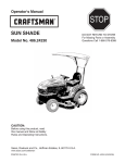
1
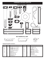
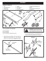
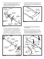
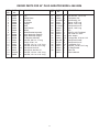
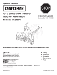
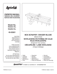
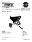
Owner's Manual
®
40" PLUG AERATOR
Model No. 486.24326
CAUTION:
Before using this product, read
this manual and follow all Safety
Rules and Operating Instructions.
STOP
DO NOT RETURN TO STORE
For Missing Parts or Assembly
Questions Call 1-866-576-8388
•
•
•
•
•
Safety
Assembly
Operation
Maintenance
Parts
Sears, Roebuck and Co., Hoffman Estates, IL 60179 U.S.A.
www.sears.com/craftsman
PRINTED IN U.S.A.
FORM NO. 40016 (REV. 05/15/08)
TABLE OF CONTENTS
SAFETY RULES............................................................... 2
FULL SIZE HARDWARE CHART..................................... 3
CARTON CONTENTS...................................................... 4
ASSEMBLY....................................................................... 4
OPERATION..................................................................... 8
MAINTENANCE............................................................. 10
STORAGE...................................................................... 10
REPAIR PARTS ILLUSTRATION................................... 12
REPAIR PARTS LIST..................................................... 13
PARTS ORDERING/SERVICE.........................Back Cover
WARRANTY
ONE YEAR FULL WARRANTY
When operated and maintained according to the instructions supplied with it, if this Plug Aerator fails due to a defect in
material or workmanship within one year from the date of purchase, call 1-800-4-MY-HOME® to arrange for free repair (or
replacement if repair proves impossible).
If this product is used for commercial or rental purposes, this warranty applies for only 90 days from the date of purchase.
This warranty gives you specific legal rights, and you may also have other rights which vary from state to state.
Sears, Roebuck and Co., D817WA, Hoffman Estates, IL 60179
The model number and serial numbers will be found on a
decal attached to the aerator.
You should record both the serial number and the date of
purchase and keep in a safe place for future reference.
MODEL NUMBER:
486.24326
SERIAL NUMBER:
__________________
DATE OF PURCHASE:
__________________
SAFETY
Any power equipment can cause injury if operated improperly or if the user does not understand how to operate the
equipment. Exercise caution at all times when using power equipment.
•
•
•
•
•
•
Read this owners manual carefully for operating and
service instructions before attempting to assemble or
operate this equipment. Be thoroughly familiar with
the proper use of this equipment.
Read the vehicle owners manual and vehicle safety
rules, and know how to operate the vehicle before
using this equipment.
Never allow children to operate the tractor or plug
aerator attachment, and do not allow adults to operate
without proper instructions.
This aerator attachment has sharp knife points.
Always handle with care and wear substantial foot
wear when operating this aerator.
Do not allow anyone to ride or sit on plug aerator
attachment frame or on towing vehicle.
Keep the area of operation clear of all persons,
particularly small children, and also pets.
•
•
•
•
•
•
Always begin with the transmission in first (low) gear
and engine at low speed, and gradually increase
speed as conditions permit.
The vehicle braking and stability may be affected
with the attachment of this equipment. Be aware of
changing conditions on slopes. Refer to safety rules in
the vehicle owner's manual concerning safe operation
on slopes. STAY OFF OF STEEP SLOPES.
Always operate up and down a slope, never across
the face of a slope
This equipment should be operated at reduced speed
on rough terrain, along creeks and ditches and on
hillsides, to prevent tipping and loss of control. Do not
drive too close to a creek or a ditch.
Do not tow this equipment on a highway or any other
public thoroughfare.
Follow the maintenance instructions as outlined in this
owners manual.
Look for this symbol to point out important safety precautions. It means — Attention!!
Become alert!! Your safety is involved.
2
HARDWARE PACKAGE CONTENTS
SHOWN FULL SIZE
A
C
B
D
E
G
F
N
L
H
M
I
Q
P
J
O
K
S
R
T
NOT SHOWN FULL SIZE
V
U
W
HARDWARE PACKAGE CONTENTS
Key
A
B
C
D
E
F
G
H
I
J
K
L
Qty.
2
4
1
8
8
1
1
2
8
8
8
2
Description
Hex Bolt, 1/2" x 3-1/2" Lg.
Hex Bolt, 1/4" x 1-3/4" Lg.
Hex Bolt, 1/2" x 1-1/4" Lg.
Hex Bolt, 3/8" x 1" Lg.
Hex Bolt, 5/16" x 3/4" Lg.
Hair Cotter Pin, Large
Hitch Pin
Nylock Jam Nut, 1/2"
Nylock Nut, 3/8"
Nylock Nut, 5/16"
Nylock Nut, 1/4"
Jam Nut, 1/2"
3
Key
M
N
O
P
Q
R
S
T
U
V
W
Qty.
1
4
4
1
1
1
1
4
2
1
8
Description
Nylock Nut, 1/2"
Flat Washer, 3/4"
Hex Bolt, 1/4" x 3/4"
Clevis Pin
Hair Cotter Pin, Small
Spacer Tube, 3.70" Long
Spacer Tube, 1" Long
Spacer Tube, 1.33" Long
Stop Bracket
Handle Grip
Split Plastic Bearing
ASSEMBLY
CARTON CONTENTS
1.
2.
3.
4.
Tray
Wheel Brackets (2)
Middle Brace
Hitch Bracket
5.
6.
7.
8.
Tongue
End Plates (2)
Lift Handle
Lift Lever Assembly
9. Single Spool Assemblies (2)
10. Shaft
11. Double Spool Assemblies (2)
12. Wheels (2)
4
5
2
1
6
3
7
12
10
8
9
11
TOOLS REQUIRED FOR ASSEMBLY
(2)
(2)
(2)
(2)
7/16" wrenches
1/2" wrenches
9/16" wrenches
3/4" wrenches or adjustable wrenches
•
Attach the lift lever assembly to the two holes in the
middle of the shaft using two 1/4" x 1-3/4" hex bolts
(B) and a 1/4" nylock nuts (K). Tighten. See figure 1.
CAUTION: Points of aerator knives
are sharp! Exercise caution at all times
while assembling and using the aerator.
•
Push split plastic bearings (Y) into both ends of all
single and double spool assemblies. See figure 2.
SPLIT
BEARING (Y)
LIFT LEVER ASSEMBLY
1/4" NYLOCK
NUT (K)
SPLIT
BEARING (Y)
SPLIT
BEARING (Y)
1/4" x 1-3/4"
HEX BOLT (B)
FIGURE 1
SPLIT
BEARING (Y)
4
FIGURE 2
•
Identify the short end of the shaft. Assemble a 1" long
spacer (S), a single spool assembly, a 1.33" long
spacer (T), a double spool assembly, another 1.33"
long spacer (T) and a 3/4" flat washer (N) onto the
short end of the shaft. See figure 3.
3/4" FLAT
WASHER (N)
•
Assemble the end plates to the ends of the tray using
four 5/16" x 3/4" hex bolts (E) and four 5/16" nylock
nuts (J) for each end plate. Do not tighten until final
step. See figure 5.
1.33" LONG
SPACER (T)
5/16" NYLOCK
NUT (J)
5/16" x 3/4"
HEX BOLT (E)
1.33" LONG
SPACER (T)
1" LONG
SPACER (S)
DOUBLE SPOOL
ASSEMBLY
FIGURE 5
SINGLE SPOOL
ASSEMBLY
SHORT END
OF SHAFT
FIGURE 3
•
Assemble the middle brace onto the long end of
the shaft with the bent end of the brace facing the lift
lever. Next assemble a 3.70" long spacer (R), a single
spool assembly, a 1.33" long spacer (T), a double
spool assembly, a 1.33" long spacer (T) and a 3/4" flat
washer (N) onto the long end of the shaft. See figure
4.
LIFT
LEVER
•
Assemble the tongue to the tray using four 3/8" x 1"
hex bolts (D) and 3/8" nylock nuts (I) as shown in
figure 6. Tighten.
•
Assemble the two stop brackets (U) to the tongue
using four 1/4" x 3/4" hex bolts (O) and 1/4" nylock
nuts (K). Position the bottom bracket as far to the right
side as possible. Position the top bracket as far to the
left side as possible. Tighten. See figure 6.
MIDDLE
BRACE
3/8" x 1"
HEX BOLT (D)
3.70" LONG
SPACER (R)
1.33" LONG
SPACER (T)
STOP
BRACKET (U)
1/4" x 3/4"
HEX BOLT (O)
RIGHT SIDE
SINGLE SPOOL
ASSEMBLY
DOUBLE SPOOL
ASSEMBLY
1.33" LONG
SPACER (T)
3/8" NYLOCK
NUT (I)
1/4" NYLOCK
NUT (K)
3/4" FLAT
WASHER (N)
FIGURE 4
LEFT SIDE
REAR VIEW
5
FIGURE 6
•
•
Assemble the hitch bracket to the tongue using two
3/8" x 1" hex bolts (D), and two 3/8" nylock nuts (I).
Tighten. See figure 7.
Assemble the hitch pin (G) through the hitch bracket
and the tongue. Secure the hitch pin with the large
hairpin cotter (F). See figure 7.
HITCH
PIN (G)
•
Assemble a wheel to a wheel bracket as shown in
figure 9. Use a 1/2" x 3-1/2" hex bolt (A), one 1/2"
hex jam nut (L), and one 1/2" nylock jam nut (H).
Adjust the nuts so that the wheel is held securely with
minimum end play but will spin freely. Repeat on other
side. See figure 9.
1/2" NYLOCK
JAM NUT (H)
3/8" x 1"
HEX BOLT (D)
1/2" JAM NUT (L)
3/8" NYLOCK
NUT (I)
HITCH
BRACKET
1/2" x 3-1/2"
HEX BOLT (A)
LARGE HAIRPIN
COTTER (F)
FIGURE 9
FIGURE 7
•
•
Turn the tray upside down. Standing behind the tray,
place the long end of the shaft through the end plate
on your right as shown in figure 8. Place the other end
of the shaft through the end plate on your left. Make
sure the bent end of the middle brace rests flat inside
the tongue.
Assemble a 3/4" flat washer (N) and a wheel bracket
onto each end of the shaft. Turn each wheel bracket
to point in the opposite direction from the lift lever.
Secure each wheel bracket with a 1/4" x 1-3/4" hex
bolt (B) and 1/4" nylock nut (K). Tighten. See figure 8.
•
Tip the aerator onto the back edge of the tray. Fasten
the middle brace to the bottom of the tongue using
two 3/8" x 1" hex bolts (D) and 3/8" nylock nuts (I). Do
not tighten until final step. See figure 10.
3/8" x 1"
HEX BOLT (D)
NOTE: If there is not enough room on the shaft for the
wheel bracket, leave off the 3/4" flat washer(s) from that
end of the shaft.
3/8" NYLOCK
NUT (I)
1/4" NYLOCK
NUT (K)
WHEEL
BRACKET
MIDDLE
BRACE
LIFT LEVER
FIGURE 10
3/4" FLAT
WASHER (N)
1/4" x 1-3/4"
HEX BOLT (B)
FIGURE 8
UPSIDE DOWN VIEW
UPSIDE DOWN VIEW
6
•
•
Turn the lift handle as shown in figure 11 and attach it
to the side of the lift lever that is indicated. Use a 1/2"
x 1-1/4" hex bolt (C) and 1/2" nylock nut (M) in the
bottom hole and the clevis pin and small hairpin cotter
in the top hole. Tighten the bolt and nut. See figure 11.
Push the grip (V) onto the lift handle. See figure 11.
• Perform the following steps in sequence to tighten the
bolts and nuts that remain loose. Refer to figure 12.
a. Turn the aerator upright, then lock the lift handle
into the transport position.
b. Tighten the eight bolts at the corners of the tray.
c. Tighten the two bolts which fasten the middle
brace to the bottom of the tray.
b
CLEVIS PIN (P)
b
b
GRIP (V)
c
b
SMALL HAIRPIN
COTTER
LIFT LEVER
1/2" NYLOCK
NUT (M)
1/2" x 1-1/4"
HEX BOLT (C)
FIGURE 12
FIGURE 11
7
OPERATION
KNOW YOUR PLUG AERATOR
Read this owner's manual and safety rules before operating your plug aerator.
Compare the illustration below with your aerator to familiarize yourself with the various controls and their locations.
LIFT HANDLE
STOP BRACKETS
LIFT HANDLE Raises the aerator to the transport position and lowers it to the operating position.
STOP BRACKETS Locks the lift handle in the transport position (upper bracket) or operating position (lower bracket).
BEFORE STARTING
HOW TO USE YOUR PLUG AERATOR
•
Aerating means pulling small soil plugs, ranging up
to three inches in length, from the soil to create small
reservoirs that will bring oxygen, fertilizer and water
down into the roots. For best aerator performance, the
following lawn preparations and operating procedures are
recommended.
•
Mow the lawn and remove loose clippings prior to use
of the aerator.
If the soil is extremely hard and dry, it is
recommended that it be sprinkled or watered down for
one or two hours prior to aerating.
•
CAUTION: Points of aerator knives are
sharp! Exercise caution at all times while
using the aerator.
•
•
CAUTION: Vehicle braking and stability
may be affected by the addition of an
accessory or attachment. Be aware of
changing conditions on slopes.
•
•
•
8
Start tractor engine with controls in neutral and place
throttle at slow engine speed.
Engage shift lever at lowest possible forward speed
and lower aerator, allowing plugger points to enter the
ground. Increase speed as conditions permit.
Aerate in the straightest line possible, making
overlapping passes to increase the plugger point
pattern.
Avoid extremely sharp turns with plugger points
engaged in ground to prevent damage to lawn.
DO NOT cross over walks or drives without first
raising the aerator to the transport position.
On sloped lawns, always aerate in an up and down
direction. DO NOT attempt to follow the contour of the
ground.
•
•
•
DO NOT attempt to aerate if ground is too wet, or
muddy.
Due to possible small rocks and gravel which can be
present in aerated soil plugs, it is recommended that
the plugs be raked; otherwise damage to the lawn
mower blades may arise, especially when reel type
mowers are used.
To increase the depth of plugger point penetration,
up to 140 lbs. of weight, such as bags of sand or (4)
concrete blocks, may be added to the tray. The weight
can be secured to the tray with ties or straps fastened
to the front and rear of the tray. Fasten so that the ties
or straps cannot become entangled on rotating parts.
See figure 13.
FIGURE 13
CAUTION: To prevent injury, dismount
from the tractor to raise or lower
aerator containing added weight.
MAINTENANCE
CUSTOMER RESPONSIBILITIES
•
Read and follow the maintenance schedule and the maintenance procedures listed in this section.
e
us se on ge
ch ch u eas tora
a
s
e e ea y s e
for fter ver efor
e
E
B
A
B
MAINTENANCE SCHEDULE
Fill in dates as you
complete regular service.
Check for loose fasteners
Cleaning
Lubrication
Service Dates
X
X
X
CHECK FOR LOOSE FASTENERS
•
LUBRICATION
Before each use make a thorough visual check of the
plug aerator for any bolts and nuts which may have
loosened. Retighten any loose bolts and nuts.
•
•
Lubricate wheels as needed.
Oil the spool assemblies and shaft as needed.
CLEANING
•
Clean dirt off of aerator knives after each use. BE
CAREFUL OF SHARP EDGES WHEN CLEANING.
SERVICE AND ADJUSTMENTS
•
Plugger points can periodically be sharpened with a
small grinder to maintain good penetration. Points
should be removed to sharpen. Follow original angle
and contour of points when grinding.
STORAGE
•
Clean the aerator and store in a dry area. Coat
exposed metal with light oil to prevent rust.
9
PARTS
REPAIR PARTS FOR PLUG AERATOR MODEL 486.24326
8
9
13
22
13
13
1
3
16
17
3
22
13
29
36
37
9
33
34
7
18
25
21
33
5
30
23
28
B
33
15
38
23
10
8
20
4
34
19
23
34
12
25
2
A
14
11
19
33
23 27
B
A
26
22
24
6
23
23 25
23
11
23
25
10
17
35
31
10
32
22
REPAIR PARTS FOR 40" PLUG AERATOR MODEL 486.24326
REF. PART QTY. DESCRIPTION
NO.
NO.
1
25853
1 Tray
2
24623
1 Middle Brace
3
24619
2 End Plate
4
25664
1 Lift Handle
5
25800
1 Tongue
6
25801
1 Shaft
7
23687
1 Hitch Bracket
8
46503
2 Wheel
9
63931
2 Wheel Bracket Assembly
10
63929
2 Spool Assembly (Double)
11
63930
2 Spool Assembly (Single)
12
65336
1 Lift Bracket Assembly
13
43001
8 Hex Bolt, 3/8-16 x 1" Long
14
43055
1 Hairpin, 3/32 x 1.8
15
43351
1 Hex Bolt, 1/2-13 x 1-1/4" Long
16
43182
8 Hex Bolt, 5/16-18 x 3/4" Long
17
47810
32 Hex Nylock Nut 5/16"
18
48115
2 Hex Nylock Jam Nut 1/2"
19 1509-69
4 Hex Bolt, 1/4-20 x 1-3/4" Long
20
46526
2 Hex Bolt, 1/2-13 x 3-1/2" Long
REF. PART QTY.
NO.
NO.
21
43019
2
22
43009
4
23 741-0493A 8
24
45151
1
25
44494
4
26 712-3083 1
27
44500
1
28
43943
1
29
47623
1
30
43343
1
31
24924 24
32
43080 24
33 HA21362 8
34
47189
8
35
43086 24
36
43012
4
37
25665
2
38
44056
1
40016
1
11
DESCRIPTION
Hex Jam Nut, 1/2-13 Thd.
Flat Washer, 3/4"
Split Bearing, 3/4"
Spacer, 3.70" Long
Spacer, 1.33" Long
Hex Nylock Nut 1/2"
Spacer, 1.00" Long
Grip
Hitch Pin, 3/8" Flat Head
Hair Cotter Pin, 3/32"
Knife, Aerator
Carriage Bolt, 5/16-18 x 3/4"
Hex Nylock Nut 3/8"
Hex Nylock Nut 1/4"
Lockwasher 5/16"
Hex Bolt, 1/4-20 x 3/4" Long
Lift Stop Bracket
Clevis Pin
Owners Manual
Get it fixed, at your home or ours!
Your Home
For repair – in your home – of all major brand appliances,
lawn and garden equipment, or heating and cooling systems,
no matter who made it, no matter who sold it!
For the replacement parts, accessories and
owner’s manuals that you need to do-it-yourself.
For Sears professional installation of home appliances
and items like garage door openers and water heaters.
1-800-4-MY-HOME®
(1-800-469-4663)
Call anytime, day or night (U.S.A. and Canada)
www.sears.com
www.sears.ca
For expert home solutions advice: www.managemyhome.com
Our Home
For repair of carry-in items like vacuums, lawn equipment,
and electronics, call or go on-line for the location of your nearest
Sears Parts & Repair Service Center
1-800-488-1222 (U.S.A.)
1-800-469-4663 (Canada)
Call anytime, day or night
www.sears.com
www.sears.ca
To purchase a protection agreement on a product serviced by Sears:
1-800-827-6655 (U.S.A.)
1-800-361-6665 (Canada)
Para pedir servicio de reparación
a domicilio, y para ordenar piezas:
Au Canada pour service en français:
1-888-SU-HOGAR®
1-800-LE-FOYER MC
(1-888-784-6427)
® Registered Trademark / TM Trademark / SM Service Mark of Sears Brands, LLC
® Marca Registrada / TM Marca de Fábrica / SM Marca de Servicio de Sears Brands, LLC
MC
Marque de commerce / MD Marque déposée de Sears Brands, LLC
(1-800-533-6937)
www.sears.ca
© Sears Brands, LLC