1
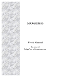
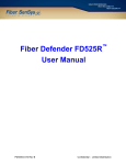
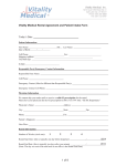
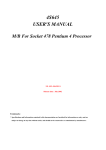
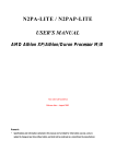
PL-FD500
Installation Guide
The PL-FD500 is an internally mounted 3.5 inch floppy disc drive unit, designed
for use with Proface’s Panel Computer, PL-5900/PL-5910 Series Units, hereafter
referred to as the “PL.”
Corresponding Product : PL-5900/PL-5910 Series Units
All product names used in this document are the trademarks of their respective
manufacturers.
Pro-face : Digital Electronics Corporation
WARNINGS
• Be sure to confirm that the PL unit’s power cord is disconnected prior to installing the FDD unit, in order to prevent electrical shock.
• Do not attempt to modify the FDD unit, due to the danger of fire or electrical
shock.
• Prior to installing the FDD unit, be sure to read section "2. Installation” completely to insure that this unit is correctly installed.
• The PL is not appropriate for use with aircraft control devices, aerospace equipment, central trunk data transmission (communication) devices, nuclear power
control devices, or medical life support equipment, due to these devices inherent requirements of extremely high levels of safety and reliability.
• When using the PL with transportation vehicles (trains, cars and ships), disaster and crime prevention devices, various types of safety equipment, non-life
support related medical devices, etc. redundant and/or failsafe system designs should be used to ensure the proper degree of reliability and safety.
To prevent this unit from malfunctioning :
• Since the FDD unit is a precision instrument, be sure that it is neither hit by nor
pressed strongly against another object.
• Be sure that water, liquids, or metal particles are not allowed to contact or
enter this unit. Either of these may cause either a breakdown or an electrical
shock.
• Do not install or operate this unit in a location where there is direct sunlight,
excessive heat, dust or vibration.
• Do not store or operate this unit near chemicals, or where there are chemical
fumes.
• To prevent damage to file data, be sure to shut down the PL unit's OS before
turning OFF the main power.
-1-
Package Contents
When you open the FDD unit’s package, please check immediately that the
following items are included.
PL-FD500
PL-FD500 Installation Guide
(This Guide)
(1)
(1)
Installation
Guide
Attachment Screws (4)
Proface has taken the utmost care to insure the quality of this product when it
was shipped. However, should, for any reason, problems or damage have occurred during shipping, please contact your Proface representative immediately
for service.
1 Hardware Specifications
Performance
Operation Mode
Disc Type (3.5 inch)
Unformatted Data Capacity
Data Transfer Speed
Disc Rotation Speed
Track Density
Track-track Seek Speed
Power Consumption
Reliability (MTBF)
2MB mode record/write
1MB mode record/write
High density type (2HD) Double density type (2DD)
2MB
1MB
500K bits/second
250K bits/second
300 rpm
135 tpi
3 ms
At start : 0.8A (typ.)
At read/write : 0.3A (typ.)
During wait : 0.01A (typ.)
30,000 hours
-2-
Environmental
Ambient Operating
Temperature
Ambient Storage
Temperature
Ambient Humidity
Vibration Resistance
Shock Resistance
5oC to 45oC
-10oC to 60oC
20%RH to 80%RH (no condensation)
(During operation)
9.8m/s2 (10Hz to 25Hz)
(During shipping) 980.7m/s2
• The above specifications are for the FDD unit only.
• Proface does not guarantee the preservation of any data stored
on the HDD if the HDD malfunctions or is damaged in any way.
Therefore, the regular backing up of important HDD data to either
a floppy disk, or other type of suitable magnetic media is strongly
recommended.
2 Installation
Be sure to use the following installation procedures to insure that the unit is
correctly installed.
WARNING
Shock Danger! Be sure to disconnect the PL unit's power cord prior to
installing the FDD Unit.
The FDD unit's installation procedure is different, depending on the PL (main
unit) type, i.e. the PL-5900T/PL-5910T or the PL-5901T/PL-5911T. The instructions given in steps 1 to 3 are the same for both the PL-5900T/PL-5910T and the
PL-5901T/PL-5911T, however the instructions used from step 4 on are different.
After completing step 1 to 3, proceed to the explanation to pertains to your specific PL unit.
1) Open the front maintenance
cover and remove the FDD’s
blank (filler) panel.
2) Close the front maintenance
cover.
FDD’s Blank (Filler) Panel <front>
-3-
FDD’s Rear Blank (Filler) Panel
3) Unscrew the two rear face
Blank Panel attachment
screws, and remove the Blank
Panel.
PL-5900T/PL-5910T (3 Slot Type)
4) Attach the Blank Panel removed in step 3) to the FDD
unit, using its two (2) attachment screws. (Do not use the
braket that comes with the
FDD unit.)
5) Insert the FDD unit into the
PL. Be sure the connectors of
the PL and the FDD unit are
securely connected.
6) Attach the FDD unit to the
PL using the FDD unit's four
(4) attachment screws. – This
includes the two (2) PL bottom face attachment screws.
Bottom face screws
-4-
PL-5901T /PL-5911T(1 Slot Type)
4) Attach the braket that comes
with the FDD unit to the FDD
unit and secure it with the two
(2) attachment screws. (Do
not use the branket removed
in step 3).
5) Insert the FDD unit into the
PL. Be sure the connectors of
the PL and the FDD unit are
securely connected.
6) Attach the FDD unit to the
PL using the FDD unit's four
(4) attachment screws. – This
includes the two (2) PL bottom face attachment screws.
Bottom face screws
Even after the unit is securely attached to the PL, part of the
unit will extend out from the PL.
-5-
3 Hardware Setup
Use the following steps to setup the hardware. Even though the BIOS screen
shown below is for PL-5900 Series unit, the PL-5910 Series setup procedures is
the same.
Certain BIOS screen items may differ from those shown here
due to new versions.
1) Connect a keyboard to the PL.
2) Turn the PL’s power ON.
3) After the message, “Press <DEL> to Enter SETUP” appears at the left bottom
of the screen, hold down the [DEL] key.
The setup utility will start and the following screen will appear.
CMOS Setup Utility - Copyright (C) 1984-2000 Award Software
4 Standard CMOS Features
4 PC Health Status
4 Advanced BIOS Features
Load Fail-Safe Defaults
4 Advanced Chipset Features
Load Optimized Defaults
4 Integrated Peripherals
Set Password
4 Power Management Setup
Save & Exit Setup
4 PnP/PCI Configurations
Exit Without Saving
ESC :Quit
↑↓→←
:Select Item
F10 :Save & Exit Setup
Time,Date,Hard Disk Type・・・
Operation Keys
Provides a list of keys used for setup procedures.
System Setting Areas
Each selection item shown here represents a separate menu area, where
settings can be entered.
4) Use the cursor to select “STANDARD CMOS SETUP,” and the following screen will appear.
-6-
CMOS Setup Utility - Copyright (C) 1984-2000 Award Software
Standard CMOS Features
Date (mm:dd:yy):
Time (hh:mm:ss):
Thu, Aug 24 2000
11 : 15 : 14
4 IDE Primary Master Press Enter10056 MB
4 IDE Primary Slave
Press Enter None
Drive A
Drive B
1.44M, 3.5 in.
None
Video
Halt On
EGA/VGA
All,But Keyboard
Base Memory
Externded Memory
Total Memory
Item Help
Menu Level 4
Change the day, month,
year and century
640K
56320K
57344K
↑↓→←:Move Enter:Select +/-/PU/PD:Value F10:Save ESC:Exit F1:General Help
F5:Previous Values
F6:Fail-Safe Defaults
F7:Optimized Defaults
5) Confirm that “Drive A:” is set to “1.44M, 3.5 in.” If the setting is different,
place the cursor on the “Drive A:” selection item and use the [PU], [PD] o r
[+], [-] key to select the “1.44M, 3.5 in.” drive setting.
6) Press the [ESC] key, and the initial (main) menu screen will appear.
7) Place the cursor on the “SAVE & EXIT SETUP” selection item and press the
[Enter] key.
8) After the “SAVE to CMOS and EXIT (Y/N)? N” message appears, press the
[Y] key to quit the setup utility.
-7-
Note
Be aware that the Digital Electronics Corporation shall not be held liable for any real or
estimated damages or losses, or third party claims resulting from the use of this product.
© Copyright 2000 Digital Electronics Corporation.
-8-