1
R
MVP Series
User's Manual
MVP Series
User's Manual
R
P/N 112301–001, Rev B
US and CANADA Radio Interference Note
Note: This device complies with Part 15 of the FCC Rules. Operation is subject to the following two
conditions: (1) this device may not cause harmful interference, and (2) this device must accept any
interference received, including interference that may cause undesired operation.
Properly shielded and grounded cables and connectors must be used in order to meet FCC emission limits.
The manufacturer is not responsible for any radio or television interference caused by using other than
recommended cables and connectors or by unauthorized changes or modifications to this equipment.
Unauthorized changes or modifications could void the user’s authority to operate the equipment.
The input/output (I/O) cable must be shielded for the printer to comply with FCC rules and regulations Part
15 governing the radiation limits for Class “A” equipment.
This Class A digital apparatus meets all requirements of the Canadian Interference–Causing Equipment
Regulations.
Cet appareil numérique de la classe A respecte toutes les exigences du Règlement sur le matériel brouilleur
du Canada.
WARNING
This is a Class A product. In a domestic environment this product may cause radio interference in which
case the user may be required to take adequate measures.
Printronix, Inc. makes no representations or warranties of any kind regarding this material, including, but not
limited to, implied warranties of merchantability and fitness for a particular purpose. Printronix, Inc. shall not
be held responsible for errors contained herein or any omissions from this material or for any damages,
whether direct, indirect, incidental or consequential, in connection with the furnishing, distribution,
performance or use of this material. The information in this manual is subject to change without notice.
This document contains proprietary information protected by copyright. No part of this document may be
reproduced, copied, translated or incorporated in any other material in any form or by any means, whether
manual, graphic, electronic, mechanical or otherwise, without the prior written consent of Printronix, Inc.
All rights reserved. Revision B. March, 1996.
TRADEMARK ACKNOWLEDGMENTS
Printronix is a registered trademark of Printronix, Inc.
MVP is a registered trademark of Printronix, Inc.
IGP is a registered trademark of Printronix, Inc.
17500 Cartwright Road, P.O. Box 19559
Irvine, California 92713
Telephone (714) 863–1900 FAX (714) 660–8682
Technical Support (714) 221–2686
COPYRIGHT 1991, 1996, PRINTRONIX, INC.
Table of Contents
1
Introduction
About This Manual . . . . . . . . . . . . . . . . . . . . . . . . . . . . . . . . . . . . . . . . . . . . 1–2
Introduction . . . . . . . . . . . . . . . . . . . . . . . . . . . . . . . . . . . . . . . . . . . . . . . . . . 1–4
Printer Features . . . . . . . . . . . . . . . . . . . . . . . . . . . . . . . . . . . . . . . . . . . . . . . 1–4
MVP–Series Printers . . . . . . . . . . . . . . . . . . . . . . . . . . . . . . . . . . . . . . . . 1–5
L150 Printers . . . . . . . . . . . . . . . . . . . . . . . . . . . . . . . . . . . . . . . . . . . . . . 1–6
150B/L150B Printers . . . . . . . . . . . . . . . . . . . . . . . . . . . . . . . . . . . . . . . . 1–6
Optional Features . . . . . . . . . . . . . . . . . . . . . . . . . . . . . . . . . . . . . . . . . . . 1–7
Character Formation . . . . . . . . . . . . . . . . . . . . . . . . . . . . . . . . . . . . . . . . . . . . 1–8
Line Matrix Printing . . . . . . . . . . . . . . . . . . . . . . . . . . . . . . . . . . . . . . . . . . . . 1–9
Print Rate . . . . . . . . . . . . . . . . . . . . . . . . . . . . . . . . . . . . . . . . . . . . . . . . . . . 1–10
Plot Rate . . . . . . . . . . . . . . . . . . . . . . . . . . . . . . . . . . . . . . . . . . . . . . . . . . . . 1–11
2
Installation
Introduction . . . . . . . . . . . . . . . . . . . . . . . . . . . . . . . . . . . . . . . . . . . . . . . . . . 2–2
Power Requirements . . . . . . . . . . . . . . . . . . . . . . . . . . . . . . . . . . . . . . . . . . . 2–3
Site Requirements . . . . . . . . . . . . . . . . . . . . . . . . . . . . . . . . . . . . . . . . . . . . . 2–4
Installing the Printer . . . . . . . . . . . . . . . . . . . . . . . . . . . . . . . . . . . . . . . . . . . . 2–5
Assembling the Pedestal . . . . . . . . . . . . . . . . . . . . . . . . . . . . . . . . . . . . . 2–5
Assembling the Paper Tray . . . . . . . . . . . . . . . . . . . . . . . . . . . . . . . . . . . 2–8
Mounting the Printer onto the Pedestal . . . . . . . . . . . . . . . . . . . . . . . . . . 2–9
Attaching the Paper Tray . . . . . . . . . . . . . . . . . . . . . . . . . . . . . . . . . . . . 2–10
Table Top Mounting . . . . . . . . . . . . . . . . . . . . . . . . . . . . . . . . . . . . . . . 2–11
Applying Power . . . . . . . . . . . . . . . . . . . . . . . . . . . . . . . . . . . . . . . . . . . 2–12
Preliminary Testing . . . . . . . . . . . . . . . . . . . . . . . . . . . . . . . . . . . . . . . . . . . 2–12
i
3
Operation
Introduction . . . . . . . . . . . . . . . . . . . . . . . . . . . . . . . . . . . . . . . . . . . . . . . . . . 3–2
Mechanical Controls . . . . . . . . . . . . . . . . . . . . . . . . . . . . . . . . . . . . . . . . . . . 3–2
Power On–Off . . . . . . . . . . . . . . . . . . . . . . . . . . . . . . . . . . . . . . . . . . . . . 3–3
Operator Panel Switches and Indicators . . . . . . . . . . . . . . . . . . . . . . . . . 3–3
Second Function Switches . . . . . . . . . . . . . . . . . . . . . . . . . . . . . . . . . . . . 3–6
Loading Ribbon . . . . . . . . . . . . . . . . . . . . . . . . . . . . . . . . . . . . . . . . . . . . . . . 3–8
Removing the Ribbon . . . . . . . . . . . . . . . . . . . . . . . . . . . . . . . . . . . . . . 3–10
Paper Guidelines . . . . . . . . . . . . . . . . . . . . . . . . . . . . . . . . . . . . . . . . . . . . . 3–11
Paper Type and Thickness . . . . . . . . . . . . . . . . . . . . . . . . . . . . . . . . . . . 3–11
Loading Paper . . . . . . . . . . . . . . . . . . . . . . . . . . . . . . . . . . . . . . . . . . . . . . . 3–12
Removing Paper . . . . . . . . . . . . . . . . . . . . . . . . . . . . . . . . . . . . . . . . . . 3–15
Setting Top–of–Form . . . . . . . . . . . . . . . . . . . . . . . . . . . . . . . . . . . . . . . . . . 3–16
Setting Forms Length . . . . . . . . . . . . . . . . . . . . . . . . . . . . . . . . . . . . . . . . . . 3–17
4
Configuration
Introduction . . . . . . . . . . . . . . . . . . . . . . . . . . . . . . . . . . . . . . . . . . . . . . . . . . 4–2
Changing Configurations . . . . . . . . . . . . . . . . . . . . . . . . . . . . . . . . . . . . . . . . 4–3
MVP/L150 . . . . . . . . . . . . . . . . . . . . . . . . . . . . . . . . . . . . . . . . . . . . . . . 4–3
150B /L150B . . . . . . . . . . . . . . . . . . . . . . . . . . . . . . . . . . . . . . . . . . . . . 4–4
Verifying Configurations . . . . . . . . . . . . . . . . . . . . . . . . . . . . . . . . . . . . . . . . 4–5
Configuration Options . . . . . . . . . . . . . . . . . . . . . . . . . . . . . . . . . . . . . . . . . . 4–6
Quick Reference Table for Configuration Options 20–61 . . . . . . . . . . . . 4–7
ii
5
Graphics
Introduction . . . . . . . . . . . . . . . . . . . . . . . . . . . . . . . . . . . . . . . . . . . . . . . . . . 5–2
Raster Plotting . . . . . . . . . . . . . . . . . . . . . . . . . . . . . . . . . . . . . . . . . . . . . . . . 5–2
Raster Plot Syntax . . . . . . . . . . . . . . . . . . . . . . . . . . . . . . . . . . . . . . . . . 5–4
Print Modes for Raster Plots . . . . . . . . . . . . . . . . . . . . . . . . . . . . . . . . . . 5–5
High Resolution Raster Plot Syntax . . . . . . . . . . . . . . . . . . . . . . . . . . . . 5–6
Scaling Graphics . . . . . . . . . . . . . . . . . . . . . . . . . . . . . . . . . . . . . . . . . . . 5–6
Exiting from Raster Plot . . . . . . . . . . . . . . . . . . . . . . . . . . . . . . . . . . . . . 5–7
Bit Image Graphics . . . . . . . . . . . . . . . . . . . . . . . . . . . . . . . . . . . . . . . . . . . . 5–8
Characteristics of Bit Image Graphics . . . . . . . . . . . . . . . . . . . . . . . . . . 5–8
Plotting a Bit Image Pattern . . . . . . . . . . . . . . . . . . . . . . . . . . . . . . . . . 5–10
Bit Image Density . . . . . . . . . . . . . . . . . . . . . . . . . . . . . . . . . . . . . . . . . 5–11
Bit Image Programming Format
Bit Image Sample Program
. . . . . . . . . . . . . . . . . . . . . . . . . . . . . 5–12
. . . . . . . . . . . . . . . . . . . . . . . . . . . . . . . . . 5–13
Other Bit Image Features . . . . . . . . . . . . . . . . . . . . . . . . . . . . . . . . . . . 5–14
P–Series Plot Mode . . . . . . . . . . . . . . . . . . . . . . . . . . . . . . . . . . . . . . . . . . . 5–15
Plot Density . . . . . . . . . . . . . . . . . . . . . . . . . . . . . . . . . . . . . . . . . . . . . . 5–15
Plot Data Byte Format . . . . . . . . . . . . . . . . . . . . . . . . . . . . . . . . . . . . . 5–16
Plot Data Line Format . . . . . . . . . . . . . . . . . . . . . . . . . . . . . . . . . . . . . 5–18
Plotting Data . . . . . . . . . . . . . . . . . . . . . . . . . . . . . . . . . . . . . . . . . . . . . 5–20
Exiting P–Series Plot Mode . . . . . . . . . . . . . . . . . . . . . . . . . . . . . . . . . 5–22
iii
6
EFVU
Introduction . . . . . . . . . . . . . . . . . . . . . . . . . . . . . . . . . . . . . . . . . . . . . . . . . . 6–2
Programming EVFU Memory . . . . . . . . . . . . . . . . . . . . . . . . . . . . . . . . . . . . 6–2
Start Load Code — 6Hex . . . . . . . . . . . . . . . . . . . . . . . . . . . . . . . . . . . . 6–2
Channel Assignment
. . . . . . . . . . . . . . . . . . . . . . . . . . . . . . . . . . . . . . . 6–3
End Load Code — 6F Hex
. . . . . . . . . . . . . . . . . . . . . . . . . . . . . . . . . . 6–4
EVFU Command Codes . . . . . . . . . . . . . . . . . . . . . . . . . . . . . . . . . . . . . 6–5
EVFU Programming Example
. . . . . . . . . . . . . . . . . . . . . . . . . . . . . . . 6–5
Troubleshooting for EVFU Programming . . . . . . . . . . . . . . . . . . . . . . . . 6–7
Using EVFU . . . . . . . . . . . . . . . . . . . . . . . . . . . . . . . . . . . . . . . . . . . . . . . . . . 6–8
EVFU/IGP Execute Form Mode . . . . . . . . . . . . . . . . . . . . . . . . . . . . . . . . . . 6–9
Relative Line Slewing . . . . . . . . . . . . . . . . . . . . . . . . . . . . . . . . . . . . . . . . . . 6–9
Clearing EVFU Memory . . . . . . . . . . . . . . . . . . . . . . . . . . . . . . . . . . . . . . . 6–11
7
Programming
Introduction . . . . . . . . . . . . . . . . . . . . . . . . . . . . . . . . . . . . . . . . . . . . . . . . . . 7–2
Control Codes (Quick Reference Tables) . . . . . . . . . . . . . . . . . . . . . . . . . . . 7–3
MVP/L150 Control Codes . . . . . . . . . . . . . . . . . . . . . . . . . . . . . . . . . . . . . . . 7–4
150B/ L150B Control Codes . . . . . . . . . . . . . . . . . . . . . . . . . . . . . . . . . . . . 7–27
8
Interface
Introduction . . . . . . . . . . . . . . . . . . . . . . . . . . . . . . . . . . . . . . . . . . . . . . . . . . 8–2
Centronics and Dataproducts Interface Characteristics . . . . . . . . . . . . . . 8–2
Centronics Interface . . . . . . . . . . . . . . . . . . . . . . . . . . . . . . . . . . . . . . . . . . . . 8–3
Dataproducts Interface . . . . . . . . . . . . . . . . . . . . . . . . . . . . . . . . . . . . . . . . . . 8–5
Interface Configuration Options 60–99 . . . . . . . . . . . . . . . . . . . . . . . . . . . . . 8–8
Switching Interfaces . . . . . . . . . . . . . . . . . . . . . . . . . . . . . . . . . . . . . . . . . . . 8–26
iv
9
Routine Service and Diagnostics
Introduction . . . . . . . . . . . . . . . . . . . . . . . . . . . . . . . . . . . . . . . . . . . . . . . . . . 9–2
Cleaning Requirements . . . . . . . . . . . . . . . . . . . . . . . . . . . . . . . . . . . . . . . . . 9–2
Before Cleaning . . . . . . . . . . . . . . . . . . . . . . . . . . . . . . . . . . . . . . . . . . . . 9–3
Cleaning the Printer . . . . . . . . . . . . . . . . . . . . . . . . . . . . . . . . . . . . . . . . . 9–5
Moving the Printer . . . . . . . . . . . . . . . . . . . . . . . . . . . . . . . . . . . . . . . . . . 9–7
Reconnecting the Cables . . . . . . . . . . . . . . . . . . . . . . . . . . . . . . . . . . . . . 9–8
Corrective Maintenance . . . . . . . . . . . . . . . . . . . . . . . . . . . . . . . . . . . . . . . . . 9–9
Self–Tests . . . . . . . . . . . . . . . . . . . . . . . . . . . . . . . . . . . . . . . . . . . . . . . . . . . 9–10
Self–Test Procedure . . . . . . . . . . . . . . . . . . . . . . . . . . . . . . . . . . . . . . . 9–10
Self–Test Configuration . . . . . . . . . . . . . . . . . . . . . . . . . . . . . . . . . . . . 9–12
Appendices
Appendix A: Character Sets and Control Codes
Appendix B: Printer Diagnosics
Appendix C: Specifications, Accessories and Options
Index
v
vi
1
Introduction
Chapter Contents
About This Manual . . . . . . . . . . . . . . . . . . . . . . . . . . . . . . . . . . . . . . . . . . . . 1–2
Introduction . . . . . . . . . . . . . . . . . . . . . . . . . . . . . . . . . . . . . . . . . . . . . . . . . . 1–4
Printer Features . . . . . . . . . . . . . . . . . . . . . . . . . . . . . . . . . . . . . . . . . . . . . . . 1–4
MVP–Series Printers . . . . . . . . . . . . . . . . . . . . . . . . . . . . . . . . . . . . . . . . 1–5
L150 Printers . . . . . . . . . . . . . . . . . . . . . . . . . . . . . . . . . . . . . . . . . . . . . . 1–6
150B/L150B Printers . . . . . . . . . . . . . . . . . . . . . . . . . . . . . . . . . . . . . . . . 1–6
Optional Features . . . . . . . . . . . . . . . . . . . . . . . . . . . . . . . . . . . . . . . . . . . 1–7
Character Formation . . . . . . . . . . . . . . . . . . . . . . . . . . . . . . . . . . . . . . . . . . . . 1–8
Line Matrix Printing . . . . . . . . . . . . . . . . . . . . . . . . . . . . . . . . . . . . . . . . . . . . 1–9
Print Rate . . . . . . . . . . . . . . . . . . . . . . . . . . . . . . . . . . . . . . . . . . . . . . . . . . . 1–10
Plot Rate . . . . . . . . . . . . . . . . . . . . . . . . . . . . . . . . . . . . . . . . . . . . . . . . . . . . 1–11
Overview
1–1
About This Manual
This manual applies to the MVP–Series of Printronix printers; the standard
MVP, L150, 150B and L150B. Explanations and descriptions that refer to
standard MVP or MVP–Series printers apply to all four printers in the series.
Chapters that address configuring and programming issues distinguish
between the MVP/L150 and 150B/L150B. This is due to the different
software pertaining to each printer. In all other areas, the four printer are
similar.
How to Locate Information
•
Use the Table of Contents at the front of the manual.
•
Use the Chapter Contents listed on the first page of each chapter.
•
Use the Index at the back of the manual.
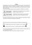
Warnings and Special Information
Read and comply with all information highlighted under special headings:
WARNING
Conditions that could harm you as well as damage the equipment.
CAUTION
Conditions that could damage the printer or related equipment.
IMPORTANT
Information vital to proper operation of the printer.
NOTE: Information affecting printer operation.
1–2
Overview
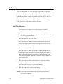
Switches, Keys, Indicators and Display Messages
Switches, indicators and switch positions on the printer are uppercase. For
example: Press and release the RDY switch.
Messages that appear on the control panel display are printed in initial capital
letters and set off with quotation marks (except for conjunctions, which are
all lowercase). For example: “Save Config” appears on the message display.
Overview
1–3
Introduction
The MVP–Series printers are line matrix printers that provide high quality
printing and graphics by printing at 200 lines–per–minute (lpm) and plotting
at 18.7 lpm in five different print modes. They offer features such as dot
matrix flexibility, plug–in PROMs that allow alternate character sets to
substitute for the standard set and the capability of printing on a wide variety
of multi–part forms, labels and other business forms.
All MVP–Series printers have a digital panel and switches that allow you to
select and control internal functions, run self–tests, and configure the printer
for selected responses to commands and data from the host computer.
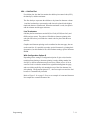
Printer Features
The Standard MVP is a sophisticated printer that has a wide variety of
printing capabilities. It provides standard features and functions that allow
you to control and define printer output. Its counterpart, the L150, offers the
Standard MVP features and functions along with additional features that
allow for especially high quality print and graphics. The 150B and L150B
not only offer all of the Standard MVP and L150 functions and features, but
they are also designed to meet the specifications of industry bar code
standards for the Department of Defense (LOGMARS), Auto Industry
(AIAG), Health Industry (HIBC), and others.
1–4
Overview
MVP–Series Printers
All MVP printers offer these standard features:
•
Alternate character sets
•
Electronic Vertical Format Unit
•
Elongated characters
•
Test pattern printing
•
Host mode control
•
Plotting
•
Slewing
•
Underlining
•
Accommodating a wide variety of forms, including card stock, adhesive
backed forms for label applications, and one–part to six–part bond for
reports.
In the normal operating mode, all MVP printers provide the following
standard functions at the control panel:
•
Placing the printer on–line or off–line
•
Changing spacing selection
•
Controlling paper advance
•
Displaying the current printer operating mode (1–5)
•
Displaying a status condition with a displayed fault code
•
Displaying the selected line spacing
In the normal operating mode, all MVP printers provide the following
standard functions from the host:
Overview
•
Changing the print mode
•
Changing the forms length
•
Configuring the printer
•
Running self–tests
•
Configuring with a Printronix Intelligent Graphics Processor (IGP–20)
to produce bar codes, labels, and business forms.
1–5
L150 Printers
In addition to the standard features and functions listed in “MVP Printers,”
the L150 printers print approximately a 0.017 inch diameter dot that assures
printed bar codes will meet demanding size and quality specifications. L150
printers also have various print modes that match dot density and resolution
to specific bar code applications:
•
MODE 2 prints text at a character pitch of 10 cpi for data processing
applications.
•
MODE 4 provides a plot density designed for bar codes such as Code
3/9, Interleaved 2/5, and Code 128. In addition, text can be printed at a
character pitch of 12.1 cpi.
•
MODE 5 provides a plot density designed for Universal Product Code
(UPC) and European Article Numbering (EAN) bar codes. In addition,
text can be printed at a character pitch of 13.3 cpi.
150B/L150B Printers
In addition to the standard features and functions listed in “MVP Printers,”
the 150B/L150B printers offer a configuration lock and unlock feature.
Special to the 150B and L150B is a raster dot matrix code configured in a
character format, which allows multi–mode character printing. These dot
matrix codes are accessed by an ASCII character code transmitted by the
computer. The flexibility of the dot matrix code structure permits the
configuration of a wide variety of characters and symbols for international
languages and graphic applications. The 150B/ L150B multi–density
graphics capabilities include plots, bar codes, graphs, block printing, and
complex curves.
1–6
Overview
Optional Features
The following are some of the various optional features offered to extend the
versatility of MVP–Series printers:
Special and Custom Character Sets
96 character ASCII; 64 character, OCR full width; EBCDIC; Block
characters; and Custom characters.
Standard MVP Density Option
Permits a four percent increase in MVP vertical dot density.
Long Lines Interface
Enables operation with a Dataproducts 2230 or 2260, differential drive,
balanced interface type controller. The interface can transfer up to 400,000
characters per second for distances up to 500 feet.
PI–3287 Printer Interface
Allows the L150 to emulate an IBM 3287 printer, and attaches to IBM 3274
or 3276 cluster controllers through Type A Interface. It may be used with or
without IGP–20 option.
IGP–20
The IGP–20 makes it easy to define, store, and then print forms and labels in
a single pass. Functions that can be performed with the IGP–20 are:
Overview
•
On–line Forms Generation - boxes, corners, vertical and horizontal
lines, logos and special form size print can be generated for a preprinted
appearance.
•
Variable Bar Codes - size, rotation, and bar code data fields are easy to
define and print.
•
Expanded characters - characters can be created up to 99 times larger
than normal for labels, titles, and signs. The vertical and horizontal sizes
of characters are controlled independently to create different
appearances.
•
Logos - expanded characters and reverse print can combine with
graphics to create customized logos. Up to 16 logos may be stored, then
called from a library for printing, either individually or in combination
with the create forms mode.
•
Compressed Print– allows up to 132 characters printed on one line of
standard 8 1/2 inch wide paper.
•
Reverse Print - allows printing reversed to white on black .
1–7
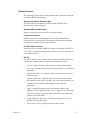
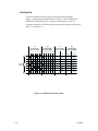
Character Formation
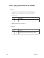
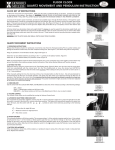
The MVP–Series printers generate characters by accumulating groups of dots
in matrices. Dot impressions are made by an assembly of 17 hammers
installed on an oscillating shuttle that impact the paper through a moving ink
ribbon. Synchronized horizontal shuttle movement and vertical paper
advancement produce overlapping dots that form solid characters
(Figure 1–1).
Figure 1–1. Typical Character Formation
1–8
Overview
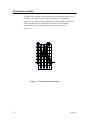
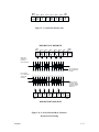
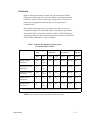
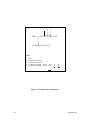
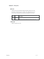
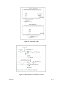
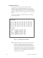
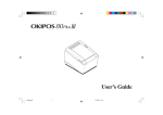
Line Matrix Printing
Unlike moving–head serial dot matrix printers, the MVP–Series printers
create graphics and characters by printing an entire dot row at one time. Dots
are printed in both directions of shuttle travel, at a printer stroke length of .2”
to print through two character positions. By printing a row of dots, dot matrix
line printers achieve higher print duty cycles than moving head dot matrix
(serial) printers.
During each sweep of the shuttle, hammers are activated to print dots at
selected positions in that dot row. When the shuttle reaches the end of a
sweep, it reverses direction, paper advances one dot row, and the hammers
print the next consecutive row of dots.
After a line of characters is printed, hammer print action ceases while the
paper advances to the first dot row of the next print line. The number of rows
allowed for line separation depends on the line spacing selected.
DIRECTION OF SHUTTLE MOVEMENT
DOT
ROW
ONE
CHARACTER
ROW
1
2
3
4
5
6
7
8
9
10
11
12
1
2
PAPER
ADVANCES
START
PAPER
FEED
*
* *
PAPER
ADVANCES
SPACE
1 HAMMER
PRINT SPAN
**
*
**
1 HAMMER
PRINT SPAN
USED FOR LOWERCASE DESCENDER ONLY
USED FOR UNDERLINE AND LOWERCASE DESCENDER
Figure 1–2. Line Matrix Printing
Overview
1–9
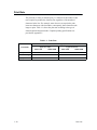
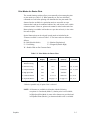
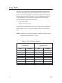
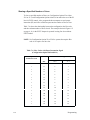
Print Rate
The print rate, in lines per minute (lpm), is a function of the number of dot
rows required to produce the character line regardless of the number of
characters in the line. For example, more dot rows are required to print
lowercase characters with descenders; consequently, those characters take
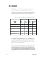
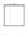
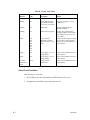
longer to print. Table 1–1 shows the print rate according to the type of
character printed and print mode. Complete printing specifications are
provided in Appendix C.
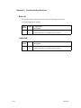
Table 1–1. Print Rate
Print Rate (lpm)
Print Mode
Uppercase (only)
MVP/L150
1–10
150B/L150B
Upper/Lowercase
MVP/L150
150B/L150B
Correspondence
80
80
62
62
Data Processing
150
150
120
120
High Speed
200
180
N/A
N/A
Overview
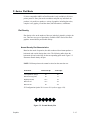
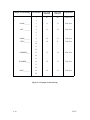
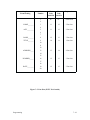
Plot Rate
The MVP–Series printers are capable of dot–addressable graphic plotting, as
well as character printing. Based on the protocol selected either P–Series or
Serial Matrix, you may select either Plot Mode or Bit Image Graphics
respectively. The plot rate specifications apply to both P–Series and Serial
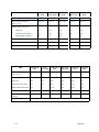
Matrix types of graphic plotting. The bi–directional plot rate in inches per
minute (ipm) is shown in Table 1–2 according to the dot density in dots per
inch, (dpi). Complete plotting specifications are provided in Appendix C.
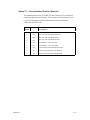
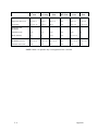
Table 1–2. Plot Rate
Plot Rate (ipm)
Density (dpi)
MVP
L150
150B/L150B
100 Horiz x 96 Vert (NLQ mode)
8.3
N/A
8.3
60 Horiz x 72 Vert (DP mode)
16.7
N/A
16.7
62.5 Horiz x 64 Vert (HS mode)
18.7
N/A
8.7
50 Horiz x 48 Vert (HSB mode)
25
13.8
27.8
100 Horiz x 72 Vert (HSC mode)
8.3
13.0
10.4
NOTE: Unidirectional plotting produces better print quality than
bi–directional, and can be selected from the control panel; however,
unidirectional plotting reduces the plot rate by half.
Overview
1–11
1–12
Overview
2
Installation
Chapter Contents
Introduction . . . . . . . . . . . . . . . . . . . . . . . . . . . . . . . . . . . . . . . . . . . . . . . . . . 2–2
Power Requirements . . . . . . . . . . . . . . . . . . . . . . . . . . . . . . . . . . . . . . . . . . . 2–3
Site Requirements . . . . . . . . . . . . . . . . . . . . . . . . . . . . . . . . . . . . . . . . . . . . . 2–4
Installing the Printer . . . . . . . . . . . . . . . . . . . . . . . . . . . . . . . . . . . . . . . . . . . . 2–5
Assembling the Pedestal . . . . . . . . . . . . . . . . . . . . . . . . . . . . . . . . . . . . . 2–5
Assembling the Paper Tray . . . . . . . . . . . . . . . . . . . . . . . . . . . . . . . . . . . 2–8
Mounting the Printer onto the Pedestal . . . . . . . . . . . . . . . . . . . . . . . . . . 2–9
Attaching the Paper Tray . . . . . . . . . . . . . . . . . . . . . . . . . . . . . . . . . . . . 2–10
Table Top Mounting . . . . . . . . . . . . . . . . . . . . . . . . . . . . . . . . . . . . . . . 2–11
Applying Power . . . . . . . . . . . . . . . . . . . . . . . . . . . . . . . . . . . . . . . . . . . 2–12
Preliminary Testing . . . . . . . . . . . . . . . . . . . . . . . . . . . . . . . . . . . . . . . . . . . 2–12
Installation
2–1
Introduction
Be sure to read this chapter carefully before installing and operating the
printer. Perform the procedures in the order presented.
CAUTION
The shipping restraints must be removed prior to operation to prevent
damage to the printer. In addition, the shipping restraints must be
installed whenever the printer or shuttle assembly is shipped or
transported to prevent damage.
VORSICHT
Um Schaden am Drucker zu verhüten, vor Gebrauch die
Verpackungseinsätze entfernen. Bei Versandt oder Transport des
Druckers oder Pendelaufbaus, die Verpackungseinsätze swecks
Schadensverhütung wieder installieren.
2–2
Installation
Power Requirements
CAUTION
MVP–Series printers employ a single phase, capacitive start shuttle
motor. All models require 120 volts at 4 amps for a duration of 0.5
seconds at motor start–up. This is an important power requirement and
is recommended to supply power from a separate AC circuit of 20 amps
at 60 Hz.
VORSICHT
Die MVP Drucker benuetzen einen ein–phasigen, kapazitive–startenden
Pendelmotor. Die MVP Modelle benoetigen beim Anlassen 0,5 Sek. lang
25,4 A. Diese Stromanforderung ist wichtig und es wird empfohlen den
Strom aus einem gesonderten AC–Stromanschluss von 20 A bei 60 Hz zu
decken.
A label on the back of the printer near the power cord shows the voltage and
frequency requirements. The printer must be connected to the specified
power source, either 110, 220 or 240 volts at 50 to 60 Hz. Line voltage can
vary by 10%. The printer automatically senses and adjusts itself to conform
to the proper voltage. The printer contains primary circuit protection. Consult
an electrician if printer operation affects local electrical lines.
Installation
2–3
Site Requirements
When selecting a printer location, consider interface requirements, power
requirements, and environmental factors. Select a location that has the proper
power source available and is within the maximum cable length
specifications for interfacing with the host computer. The printer is designed
to operate in a relatively dust free environment such as a computer room or
business office with an ambient temperature of 5° to 40° C (41° to 104° F),
and a relative humidity of 10% to 90%. The site selected for the printer must
also allow air to circulate freely all around the printer. Finally, a minimum of
three feet clearance behind the printer should be provided to allow air
circulation and easy access to the paper stacking area.
CAUTION
The warranty may be voided if adequate printer ventilation is not
provided. Overheating and serious damage to printer components can
occur if the air vents at the sides and bottom of the printer are blocked.
VORSICHT
Die Gewährleistung könnte ungültig werden, wenn nicht genügen
Druckerlüftung vorhanden ist. Überhitzung und schweren Schaden der
Druckerkomponenten könnte vorkommen, wenn die Entlüftungsschlitze
an den Seiten und unten am Drucker blockiert sind.
2–4
Installation
Installing the Printer
If you’ve ordered the Printronix pedestal mounting kit, follow the pedestal
assembly procedures before installing the printer.
Assembling the Pedestal
To assemble the optional pedestal for pedestal model printers perform the
following steps. A 5/16 inch nut driver and 5/32 inch hex wrench are
required. Check for the following items in the pedestal ship kit before you
begin assembly:
•
2 pedestal legs
•
1 modesty panel (large panel)
•
1 paper guide panel (small panel)
•
16 hex bolts
•
4 washers
•
1 paper tray
Prepare for Assembly
1.
Installation
Unpack and lay the pedestal parts on the floor. The mounting holes on
the legs should face up.
2–5
Assemble the Two Legs and Modesty Panel
2.
Align the mounting holes of the modesty panel with the holes on the left
leg as illustrated. Insert and lightly tighten bolts in the two side and
bottom rear panel holes. Proceed with the right leg; align the mounting
holes, insert and lightly tighten bolts.
modesty panel
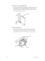
Add the Paper Guide Panel
3.
Position the paper guide panel between the modesty panel and leg
mounting holes, and align the mounting holes. The foam side of the
panels should face each other, with the foam–covered lips facing up.
paper guide panel
pedestal leg
modesty panel
2–6
foam
Installation
4.
Insert and hand tighten bolts in the bottom left and right mounting holes
in the paper guide panel. Align the top mounting holes on the modesty
panel, paper guide panel, and left leg. Insert and hand tighten bolts
through the top left and right mounting holes.
paper guide panel
pedestal leg
modesty panel
Adjust and Tighten
5.
Installation
Firmly tighten all bolts.
2–7
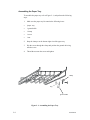
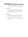
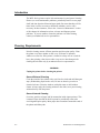
Assembling the Paper Tray
To assemble the paper tray refer to Figure 2–1, and perform the following
steps.
1.
Make sure the paper tray kit contains the following items:
•
1paper tray
•
1 ground cable
•
1 clamp
•
1 screw
•
1 nut
2.
Snap the clamp over the bottom right rim of the paper tray.
3.
Slip the screw through the clamp and position the ground cable ring
onto the screw.
4.
Thread the nut onto the screw and tighten.
clamp
ring
ground cable
Figure 2–1. Assembling the Paper Tray
2–8
Installation
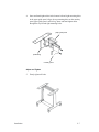
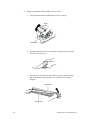
Mounting the Printer onto the Pedestal
To mount the printer onto the pedestal you need a 5/32 inch Allen wrench.
1.
Set the printer on a stationary table or desk. Remove the four rubber
feet from the printer by carefully sliding the printer over the edge of the
table to access two feet. Use the Allen wrench to remove the feet. Turn
the printer to the other side and remove the two remaining feet.
2.
Carefully set the printer on the top of the pedestal. The front cover and
the small panel should face the same direction.
3.
Align the foot mounting holes with the four holes on the top of the
pedestal. Place the washers on the four bolts and insert each through the
pedestal base as illustrated. Firmly tighten the bolts.
Figure 2–2. Mounting the Printer onto the Pedestal
Installation
2–9
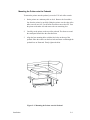
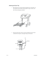
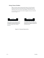
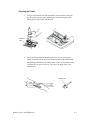
Attaching the Paper Tray
1.
Hook the paper tray into the pedestal mounting holes as illustrated. Use
the upper holes when stacking small quantities of paper, and the lower
holes when stacking larger quantities.
2.
Push the ground cable connector onto the protruding metal tab located
on the back of the printer, to the right of the power connector.
metal tab
2–10
Installation
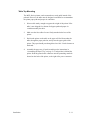
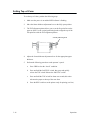
Table Top Mounting
The MVP–Series printers can be mounted on a sturdy table instead of the
pedestal. However, the table must be designed or modified to accommodate
the printer paper path and proper air ventilation.
Installation
1.
Select a table sturdy enough to support the weight of the printer. If the
table is not designed for a bottom feed paper path and proper air
ventilation modify the table.
2.
Make sure the four rubber feet are firmly attached to the base of the
printer.
3.
Position the printer on the table so the paper will feed from under the
table, through the paper path slot, and up into the paper guide of the
printer. The paper should pass through the slot with 1/2 inch clearance at
both ends.
4.
Assemble the paper tray (if used) according to the instructions in
“Assembling the Paper Tray” on page 2–8, and position it behind the
printer. Push the ground cable connector onto the protruding metal tab
located on the back of the printer, to the right of the power connector.
2–11
Applying Power
After you properly install the printer, apply power by performing the
following steps.
1.
Check that the voltage shown on the printer identification label (located
at the right rear of the printer) is the same as your power source. Voltage
in North America is usually 120 volts/60 Hz, and printers sold in the
United States are configured for power in that range. If your printer
label reads V120 VAC and your power source is also 120 volts, plug the
female end of the power cord into the male connector on the right rear
of the printer. Plug the male end into the wall outlet.
WARNING
Operator hazard and printer damage is possible if the printer is
connected to an incorrect power source.
2.
Press the ON/OFF switch to ON. When you press the power switch to
On, all indicators will light for approximately two seconds, and the
RDY indicator remains lit to show the printer is on–line.
NOTE: The power On–Off switch is located at the rear of the printer and is
marked “O” for power off, and “I” for power on.
3.
After loading the ribbon and paper, conduct a self–test as described in
the Routine Service and Diagnostics chapter.
Preliminary Testing
After you install and apply power to the printer, it is ready for preliminary
testing. Refer to the “Self Tests” section in the Routine Service and
Diagnostics chapter for the self–test instructions that apply to your specific
type of MVP printer. Once the self–test has been completed, examine the
print quality. The characters should be fully formed and of uniform density.
If the test does not run or characters appear malformed, contact your
authorized service representative.
2–12
Installation
3
Operation
Chapter Contents
Introduction . . . . . . . . . . . . . . . . . . . . . . . . . . . . . . . . . . . . . . . . . . . . . . . . . . 3–2
Mechanical Controls . . . . . . . . . . . . . . . . . . . . . . . . . . . . . . . . . . . . . . . . . . . 3–2
Power On–Off . . . . . . . . . . . . . . . . . . . . . . . . . . . . . . . . . . . . . . . . . . . . . 3–3
Operator Panel Switches and Indicators . . . . . . . . . . . . . . . . . . . . . . . . . 3–3
Second Function Switches . . . . . . . . . . . . . . . . . . . . . . . . . . . . . . . . . . . . 3–6
Loading Ribbon . . . . . . . . . . . . . . . . . . . . . . . . . . . . . . . . . . . . . . . . . . . . . . . 3–8
Removing the Ribbon . . . . . . . . . . . . . . . . . . . . . . . . . . . . . . . . . . . . . . 3–10
Paper Guidelines . . . . . . . . . . . . . . . . . . . . . . . . . . . . . . . . . . . . . . . . . . . . . 3–11
Paper Type and Thickness . . . . . . . . . . . . . . . . . . . . . . . . . . . . . . . . . . . 3–11
Loading Paper . . . . . . . . . . . . . . . . . . . . . . . . . . . . . . . . . . . . . . . . . . . . . . . 3–12
Removing Paper . . . . . . . . . . . . . . . . . . . . . . . . . . . . . . . . . . . . . . . . . . 3–15
Setting Top–of–Form . . . . . . . . . . . . . . . . . . . . . . . . . . . . . . . . . . . . . . . . . . 3–16
Setting Forms Length . . . . . . . . . . . . . . . . . . . . . . . . . . . . . . . . . . . . . . . . . . 3–17
Operation
3–1
Introduction
This chapter briefly provides instructions and information on how to
manipulate the mechanical controls, power switch, external function switches
and internal function switches on MVP–Series printers.
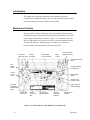
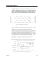
Mechanical Controls
Become familiar with the mechanical controls for loading ribbon and paper,
adjusting the paper position and the forms adjustment thickness lever, before
you attempt to perform any procedures. Figure 3–1 is an interior view of an
MVP with the shuttle cover removed to expose various mechanical controls,
switches and indicators. Study this figure in relation to your printer to
become familiar with the positions of the items specified.
Left Tractor
(with open gate)
Shuttle
Assembly
Hammerbank
Cover Assembly
Right
Tractor
Forms Thickness
Adjustment Lever
Vertical Positioning
Knob
Left
Ribbon
Guide
Shuttle Assembly
Locking Knob
Shuttle
Cover
Guide
Right Ribbon
Guide
Shuttle Cover
Position Guide
Right Transport
Restraining Bolt
Transport
Restraining
Bolt Storage
Slots
Ribbon Hub
with Latch
Shuttle
Cover Tab
Slot
Left Transport
Restraining Bolt
Operator
Panel and
Switches
Shuttle Cover
Tab Slot
Figure 3–1. Printer Interior View (Shuttle Cover Removed)
3–2
Operation
Power On–Off
The power On–Off switch is located at the rear of the printer and is marked
“O” for power off, and “I” for power on. When you press the power switch
to “I”, all function indicators light for approximately two seconds, and the
RDY indicator remains lit to show the printer is on–line.
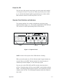
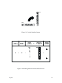
Operator Panel Switches and Indicators
The operator panel has five switches with indicators, and a three–digit
numerical display (Figure 3–2). The switches, labeled RDY, CHK, 8LPI and
TOF, each have a small Light Emitting Diode (LED) indicator.
Digital
Panel
MODE
F/L
ADDR
DATA
RDY
CHK
8LPI
TOF
Indicator
2nd
FUNC
Switch
Figure 3–2. Operator Panel
NOTE: Printer will not operate if the CHK indicator is flashing.
When you turn the printer on, all four indicators light for approximately two
seconds. However, the RDY indicator remains lit to show the printer is
controlled by the host computer, on–line and ready to print.
You can only use the CHK, 8LPI and TOF switches when the printer is
off–line. To take the printer off–line, press the RDY switch until the indicator
flashes. The flashing indicator shows the printer is not controlled by the host
computer, and is off–line. The following descriptions outline the switches in
more detail.
Operation
3–3
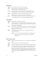
RDY (Ready)
Purpose
Indicates the printer is on–line and ready to print.
Status
When the indicator is flashing, the printer is off–line.
When the indicator is lit, the printer is on–line.
Action
To put the printer on–line; press and release, until the indicator is lit.
To take the printer off–line; press and release, until the indicator flashes.
Result
When the printer is on–line, none of the other switches are active.
When the printer is off–line, use the front panel function keys.
Other
If the printer is connected to the host, the host controls the printer when it is
on–line. When the printer is off–line, the host no longer has control.
CHK (CHECK)
Purpose
Indicates there is a problem or malfunction.
Status
When the indicator is lit or flashing the printer is malfunctioning. A fault
code indicating the type of problem will appear in the display. (Explanations
of the codes are in Appendix B.)
Action
If the indicator is flashing, check the fault code, fix the problem and reset the
printer by pressing and releasing. If the indicator is lit, it is more than likely
the printer needs to be serviced.
Other
On occasion, you may be able to correct a steady indicator problem by
pressing and releasing.
NOTE: The printer will not operate when the indicator is flashing or is lit.
Therefore, you must take some action to restore the printer to
working order.
8LPI (8 Lines Per Inch)
3–4
Purpose
Allows for alternate spacing of either 8, 9 or 10 lines per inch. The default is
6 LPI.
Status
When the indicator is lit, an alternate LPI is selected.
Action
To select an alternate LPI, press and release until the desired LPI is selected.
Other
Alternate spacing options are only available when the appropriate value has
been assigned to printer configuration option 51. (See the Configuration
chapter for more details on configuration options.) Line spacing may also be
controlled by the host by using the appropriate command sequences. If an
alternate LPI is selected, the 8LPI indicator will be lit, as if it were set from
the panel.
Operation
TOF (Top–of–Form)
Purpose
Advances the paper or adjusts top–of–form one line or one page at a time.
Status
The indicator is always off, you must press to activate.
Action
To move the paper one line; press and release very quickly. To move the
paper one page or the to the top of the next form; press and hold for about
one second.
Other
Reset the TOF each time you load paper. Setting TOF after a paper load is
described on page 3–16.
F/L (Form Length)
Purpose
Allows the top of the page to begin in the same place on unusual length
forms.
Status
The indicator is always off.
Action
Press to activate.
Other
Paper that is a nonstandard length will need to have the new length set. You
can select any length from 3 inches to 24 inches in one–half inch increments.
Operation
3–5
Second Function Switches
The operator panel has second function capabilities, and you can access them
by pressing the 2nd FUNC key with either the MODE, F/L, ADDR or TOF
switches. The printer configuration set at the factory will satisfy most
printing requirements. However, when it becomes necessary to modify the
way the printer responds to commands (printer reconfiguration) use the
second function features. See page 4–4for further information on
reconfiguration.
The second function switches also allow you to change print modes, set
forms length, top–of–form and print various self–test patterns. The following
descriptions outline the switches in more detail.
2nd FUNC
Purpose
Activates second operation of selected switches or returns to normal
operation.
Status
The indicator is always off, you must press to activate.
Action
When the indicator is lit, the printer is in 2nd FUNC mode.
When the indicator is off, the printer is in the normal operation mode.
Result
When the indicator is lit, only the MODE, F/L, ADDR and TOF can be used.
MODE
3–6
Purpose
Selects print modes 1–5 (1–6 for 150B printers).
Status
The indicator is always off, you must press to activate.
Action
Press and release to display current mode.
To select desired print mode, press and release to cycle through print modes
by 001.
Result
After selecting print mode, press and release 2nd FUNC to print in the
selected print mode.
Other
The selected print mode will continuously display during printing. Refer to
page 5–5for detailed printer mode specifications.
Operation
F/L
Purpose
Sets forms length from 3.0 to 24.0 inches in 0.5 increments. Verifies proper
forms length when changing paper. See page 4–36 for proper configuration.
See page 3–17 for the procedure to set the forms length.
Status
The indicator is always off, you must press to activate.
Action
Press and release to display current length.
To select desired forms length, press and release to advance by 0.5
increments. Press and hold for rapid advance. Display cycles from 03.0 to
24.0 inches.
Result
After selecting print mode, press and release 2nd FUNC to print with the
selected forms length.
ADDR
Purpose
Selects and changes the configuration address in the numeric display
(00 – 99).
Status
The indicator is always off, you must press to activate.
Action
Press and release to display current two–digit memory address code.
To select desired address, press and release to advance by 01 increments.
Press and hold for rapid advance. Display cycles from 00 to 99.
Result
After selecting the desired print test, press and release 2nd FUNC to print
the selected table or test pattern.
Other
See page 9–10 for the Self–Test Procedure.
Refer to page 4–3for the Configuration Change Procedure.
DATA
Purpose
Selects one of up to nine options (.0 – .9) for each configuration address.
Status
The indicator is always off, you must press to activate.
Action
Refer to page 9–10 for the Self–Test Procedure.
Refer to page 4–3for the Configuration Change Procedure.
Operation
3–7
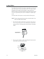
Loading Ribbon
The standard ribbon for MVP–Series printers is nylon fabric, one–inch by 60
yards, spool to spool, (Printronix part number 107675). The ribbon rewinds
automatically to the supply side when installed, so either spool may be
installed on either hub. The ribbon should be replaced when the print contrast
is too low, or approximately after each box of standard size computer paper
is used.
To load the ribbon, lift the printer cover and perform the following steps.
NOTE: The power does not need to be on when you load the ribbon. If it is,
make sure the RDY light is flashing.
1.
Move the forms thickness adjustment lever to the base of the printer as
far as it will go. (If the power is on, the CHK indicator will flash when
you move the lever.) The ribbon mask in back of the ruler will separate
slightly.
Forms Adjustment
Thickness Lever
2.
Place one spool of ribbon on a hub so the locking latch snaps into place
and the ribbon unwinds toward the outside.
Locking
Latch
Hub
3–8
Operation
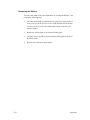
3.
Pass the ribbon around the ribbon guides. Carefully place the ribbon
between the ribbon mask and the ribbon guides, ensuring the ribbon is
not twisted. Place the second spool of ribbon on the other hub so the
locking latch snaps into place and the ribbon winds toward the inside.
Adjust the tension by hand–winding the spool.
Ribbon
Guides
NOTE: A twisted ribbon will affect the print quality, shorten the ribbon life,
and cause a paper or shuttle jam.
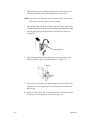
4.
If paper is loaded, adjust the forms thickness adjustment lever for the
appropriate position that is correct for the thickness of the paper.
Pointer
5.
If the printer power remained on during ribbon loading, press the CHK
switch. If there is no paper in the printer, the CHK indicator will
continue to flash.
NOTE: Ribbon loading directions are also shown on the black plastic
shuttle cover inside the printer.
Operation
3–9
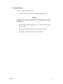
Removing the Ribbon
To remove the ribbon refer to the illustrations in “Loading the Ribbon,” and
perform the following steps.
3–10
1.
Move the forms thickness adjustment lever to the base of the printer as
far as it will go. (If the power is on, the CHK indicator will flash when
you move the lever back.) The ribbon mask in back of the ruler will
separate slightly.
2.
Release the locking latch on one hub and lift the spool.
3.
Carefully remove the ribbon from around the ribbon guides and out of
the ribbon mask.
4.
Remove the second spool from its hub.
Operation
Paper Guidelines
Paper used with the MVP–Series printers must meet the following
guidelines:
•
One–to–six parts, with or without carbon, continuous, and fan–folded
•
Six–edge standard sprocket holes
•
From 3 to 16 inches wide, including strips with the sprocket holes
•
From 3 to 24 inches long
•
Uniform thickness, including the sprocket hole edge strips, not to
exceed 0.025 inches
•
15 to 100 lb. stock
•
Interleaf attachment must not be metal or other hard material
•
Labels on backing must be at least 1/16–inch from the fan–fold edge
perforation and not have excess adhesive that can be pressed out when
the label is printed
•
Fan–fold forms should go through the printer without bunching or any
distortion of the paper
Paper Type and Thickness
Paper type and thickness will affect print quality. Therefore, take both
thickness and type under consideration when determining where to position
the forms thickness adjustment lever. The three ridges on the lever are
reference points for paper thickness that can be from one–to–six parts thick.
The forward (closed) lever position is for thinner paper. The back (open)
lever position is for thicker paper. For example, the forms thickness
adjustment lever should be positioned near the middle ridge when using
three–part paper and usually at the last ridge for one–part paper.
NOTE: Always use full size computer paper (91/2 x 11 inches or larger)
when performing self–tests.
Operation
3–11
Loading Paper
To load paper lift the printer cover and perform the following steps. Read all
of the instructions before loading the paper.
NOTE: The power does not need to be on when you load paper. If it is,
make sure the RDY light is flashing.
1.
Move the forms thickness adjustment lever to the base of the printer as
far as it will go. (If the power is on, the CHK indicator will flash when
the lever is moved or when the printer is out of paper.)
Forms AdjustmentThickness Lever
2.
Pull the right tractor lever (the plastic lever to the right of the tractor)
down to unlock it, then open both tractor gates. If you keep the left
tractor stationary you will have less to adjust later.
NOTE: The tractor levers on some printers must be pulled up to unlock and
pulled down to lock.
3–12
Operation
3.
Feed the paper into the slot from underneath if the printer is on a
pedestal or from the front if the printer has a front feed attachment.
Continue to feed the paper until it passes between the ribbon mask and
the wide metal bar.
Paper
Pedestal
Slot
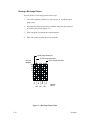
4.
Load paper on the left tractor sprocket pins and close the tractor gate.
Load paper on the right tractor sprocket pin. Make sure the paper is
aligned horizontally (the correct holes are across from one another), and
close the right tractor gate.
Sprocket Holes
5.
If the left tractor was kept stationary, proceed to step 7. If not, slide both
tractors so that the edge of the paper lines up with the first mark on the
printer’s ruler, or where you want the left margin to print. Lock the left
tractor lever (the black lever).
Ruler
Operation
3–13
6.
Adjust the right tractor so that the paper has just enough tension to be
flat and taut without pulling. Pull the right tractor up to lock it.
NOTE: Too much or too little paper tension may distort the sprocket holes
and cause problems in paper feeding or printing.
7.
Advance the paper with the positioning knob so the paper will feed out
of the opening between the raised cover and the top of the printer. Make
sure the paper supply from the bottom will feed into the printer in a
straight line.
Positioning Knob
8.
Adjust the forms thickness adjustment lever to the appropriate paper
thickness. Refer to “Paper Type and Thickness” on page 3–11.
Pointer
9.
If the power was on while you loaded the paper, press the CHK switch.
If the power was off, turn the power on and then press and release the
RDY switch.
10. Set top–of–form (TOF). Top–of–form should be set each time the paper
is loaded, refer to “Setting Top–of–Form” on page 3–16.
3–14
Operation
Removing Paper
To remove paper, follow these steps.
1.
Tear off the paper at the first perforation just under the printer.
CAUTION
Pulling the paper down through the printer could damage the printing
mechanisms.
Operation
2.
Move the forms thickness adjustment lever to the base of the printer as
far as it will go.
3.
Open both tractor gates and lift the paper from the sprockets.
4.
Pull the paper carefully upward and out of the printer.
3–15
Setting Top–of–Form
To set the top–of–form, perform the following steps.
1.
Make sure the power is on and the RDY indicator is flashing.
2.
Move the forms thickness adjustment lever to the fully open position.
3.
The TOF alignment pointer allows you to set the first print line on the
paper or form. Use the vertical positioning knob to align the top of the
first print line with the TOF alignment pointers.
vertical positioning knob
3–16
4.
Adjust the forms thickness adjustment lever for the appropriate paper
thickness.
5.
Perform the following procedure on the operator’s panel:
a.
Press CHK to clear the “check” condition.
b.
Press and hold the 2nd FUNC switch, then press and quickly
release the TOF switch. Release the 2nd FUNC switch.
c.
Press and hold the TOF switch for about one second; this action
advances the paper to the top of the next form.
d.
Press the RDY switch to set the printer ready for printing (on–line).
Operation
Setting Forms Length
To set the forms length, follow these steps.
1.
Press and release the 2nd FUNC switch.
2.
Press the F/L switch; the indicator will remain lit and the current forms
length will display on the digital panel.
3.
Press and quickly release the F/L switch to advance the number by 1/2
inch or press and hold the F/L switch until the number you want
displays. After the number advances to 24 (24.0), it will automatically
begin again at 3 (3.0).
4.
If you want the printer ON–LINE, (ready to print) after setting the new
forms length, press the 2nd FUNC switch to turn its indicator off. When
the indicator goes off, the RDY indicator will flash. Press the RDY
switch.
NOTE: If you want to return to your original forms length setting, reset to
that length by following the directions above or turn the power off
and the current forms length will reset automatically. Forms length
displayed can be from either the host computer or the printer
EAROM. Pressing the F/L switch will reset forms length to the
EAROM value resulting in a forms length different than that
generated by the host. Host forms length can be defined in either
inches ()1.0 to 22.0) or lines (001 to 127). Only forms length in
inches can be specified from the printer front panel.
Operation
3–17
3–18
Operation
4
Configuration
Chapter Contents
Introduction . . . . . . . . . . . . . . . . . . . . . . . . . . . . . . . . . . . . . . . . . . . . . . . . . . 4–2
Changing Configurations . . . . . . . . . . . . . . . . . . . . . . . . . . . . . . . . . . . . . . . . 4–3
MVP/L150 . . . . . . . . . . . . . . . . . . . . . . . . . . . . . . . . . . . . . . . . . . . . . . . 4–3
150B /L150B . . . . . . . . . . . . . . . . . . . . . . . . . . . . . . . . . . . . . . . . . . . . . 4–4
Verifying Configurations . . . . . . . . . . . . . . . . . . . . . . . . . . . . . . . . . . . . . . . . 4–5
Configuration Options . . . . . . . . . . . . . . . . . . . . . . . . . . . . . . . . . . . . . . . . . . 4–6
Quick Reference Table for Configuration Options 20–59 . . . . . . . . . . . . 4–7
Configuration
4–1
Introduction
Configuration refers to a set of option choices that define printer responses to
operational commands. The printer responds to the particular set of
commands it receives through either user–selected configuration choices or
factory defaults that are functional unless you reconfigure a specific default.
NOTE: Configuration options must be provided for printer control firmware
locations.
The printer can be configured by one of three methods:
•
Factory default options that take effect when the printer is turned on,
provided no other options have been set.
•
Partial or total options set by you that take effect when the printer is
turned on.
•
Options entered by you after the printer is turned on.
The ADDR and DATA keys are used to select the available configurations
and options. The ADDR key is used to select the configuration number, and
the DATA key is used to select the option number.
The display at the left of the operator’s panel shows a three–digit
configuration number in the form of XX.Y, where:
•
The two left digits (XX) represent the current configuration address
from 00 to 99.
•
The right digit (or third digit), (.Y), represents the option number from
.0 to .9.
MODE
F/L
ADDR
DATA
RDY
CHK
8LPI
TOF
2nd
FUNC
XX Y
Figure 4–1. Operator’s Control Panel
4–2
Configuration
Changing Configurations
You can change configuration options by following the procedure particular
to your MVP printer. For 150B and L150B printers, the configuration option
procedures release the Configuration Safety Lockout, then locks it after
changes are made.
MVP/L150
1.
Press and release the RDY switch until the indicator flashes.
2.
Press and release the 2nd FUNC switch until the indicator lights.
3.
Press and release the ADDR key until the display shows a configuration
option.
NOTE: Continue pressing and releasing ADDR until the desired
configuration option displays. To view any of the values, press and
hold ADDR. The displayed configuration option numbers cycle
through 00 to 99.
4.
First press and hold the DATA key, then press and release the MODE
switch until the DATA indicator lights. Release DATA when the current
configuration option and number displays.
5.
Repeatedly press and release DATA until the desired configuration
number displays.
6.
Press ADDR to load the configuration and its number, and to advance to
the next configuration option.
7.
Press 2nd FUNC to exit .
NOTE: If values in configuration options 67–90 are changed, turn the
printer off and on after all configurations are keyed in to reinitialize
the serial version, USART
8.
Configuration
Repeat steps 1 thru 7 until all desired configurations are made.
4–3
150B/L150B
1.
Press and release the RDY switch until the indicator flashes.
2.
Press and release the 2nd FUNC switch until the indicator lights.
3.
Press and hold the ADDR key until the display shows 16.0. Press and
release the DATA key until the display reads 16.3.
4.
Press and release 2nd FUNC until the RDY indicator flashes.
NOTE: At this point, the printer is off–line and ready to enable
reconfiguration. Repeat steps 5 thru 9 until all desired
configurations are made.
5.
Press and release 2nd FUNC until the indicator lights, then press and
release ADDR. The current configuration option and number will
display.
6.
Press and release ADDR to advance the configuration options by 01.
NOTE: Pressing and holding ADDR will advance the options continuously;
release it when the desired configuration displays.
7.
First press and hold DATA, then press and release MODE to select the
third digit. When the digit is selected, release DATA.
8.
Press and release DATA to advance the third digit by 01. Repeatedly
press and release it until the desired configuration number displays.
9.
Press and release 2nd FUNC to put the new option number into printer
memory. Press and hold ADDR until the display reads 16.3
10. Press and release DATA until the display reads 16.4; this step locks out
accidental reconfiguration.
11. Press and release 2nd FUNC to return the printer to off–line, and to lock
in the new configuration.
4–4
Configuration
Verifying Configurations
Verify the printer configuration to ensure that the appropriate response is
received for a particular application. To verify a configuration:
1.
Print out a configuration self–test using the Self Test Procedure on page
9–10to set the configuration option to 00.1. (Make sure the printer is
on–line.)
2.
Compare the values of configuration options 20 through 99 with
application requirements. Refer to the “Self–Tests” in Chapter 9 for a
complete list of self–tests and instructions that apply to your type of
MVP printer.
3.
Use the explanations for configuration options 20 through 99 to
determine the configuration settings selected.
NOTE: Use the explanations for configuration options 20 through 99 to
determine the configuration settings selected. Explanations for
standard MVP/L150 and 150B/L150B configuration options 20–59
begin on page 4–7. Configuration options 60 through 99 are
discussed in the Interfaces chapter. Addresses 00–19 are test and
service printout addresses.
4.
Configuration
Change the configuration options as necessary to meet application and
interface requirements.
4–5
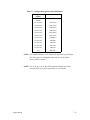
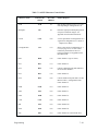
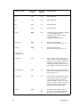
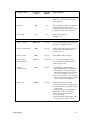
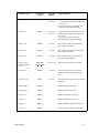
Configuration Options
After assembling and interfacing the printer, configuration changes are
usually limited to configuration options 20 through 59. Options 60 through
99 are only changed when it is necessary to reconfigure the printer for a new
interface. Configuration addresses 00 through 19 are print and service tests.
Table 4–1 is a sequential cross–reference of Standard MVP/L150 and
150B/L150B Configuration Options 20 through 59. Use the page numbers to
access the option descriptions.
4–6
Configuration
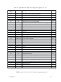
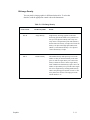
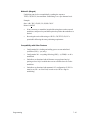
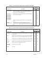
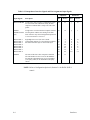
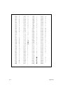
Table 4–1. Quick Reference Table for Configuration Options 20 – 59 1
Configuration
Number
Printer Type
20
MVP/L150
20
150B/L150B
21
Configuration Option
Page #
Host Mode Control Programming Standard
4–8
Double Wide Print Operation (Expanded Print Select)
4–9
All
Vertical Dot Density
4–10
22
All
Insert automatic Line Feed in Data Stream
4–11
23
All
Automatic Line Feed on Carriage Return
4–12
24
All
Inhibit Lowercase/Underline and Translate Lowercase to Uppercase
4–13
25
All
Binary Count Slew
4–14
26
All
Printer On–line with Power On
4–15
27
All
Paper Out Delay
4–16
28
All
Underline
4–17
29
All
Delete
4–18
30
All
Print or Graphics Mode at Power On
4–19
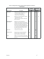
31–41
MVP/L150
Control Code Assignments
4–20
31–41
150B/L150B
Control Code Assignments
4–25
42
All
Electronic Vertical Format Unit (EVFU)
4–27
43
All
Plotting Exit
4–28
44
All
Buffer Print with Top–of–Form (TOF)
4–29
45
150B/L150B
Mode 4
4–30
46
150B/L150B
EVFU Control with no PI
4–31
47
150B/L150B
SOH and ETX 21
4–32
48
150B/L150B
Character Per Inch in Mode 5
4–33
50
All
Page Perforation Skip
4–34
51
All
Lines Per Inch (LPI) Line Spacing
4–35
52
All
Forms Length at Printer Powerup
4–36
54
150B/L150B
Lines Per Inch–Line Spacing at Power Up
4–37
56
150B/L150B
Column Print Spacing
4–37
57
150B/L150B
Input Buffer Sizes
4–38
58
150B/L150B
ESC DC1 Sequence
4–38
59
150B/L150B
Version
4–38
NOTE: Options 60–99 are located in Chapter 8 beginning on page 8–8.
Configuration
4–7
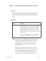
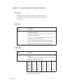
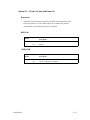
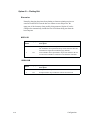
Option 20 — Host Mode Control Programming Standard
Discussion
Option 20.0 is used to store data that allows you to select the Host Mode
Control. Option 20.1 allows up to 11 beginning characters (or headers) of
control code sequences that are valid when encountered in the data stream;
option 20.2 allows only one.
MVP/L150
4–8
Option
Number
Display
Configuration
Description
.0
20.0
Host Mode Control disabled (default)
.1
20.1
P–Series programming standard. (Control Code sequence for more
changes appearing in data stream are edited per conditions attached
to Configuration options 31 through 41.)
.2
20.2
ANSI programming standard. Control Code sequence for mode
change must begin with ESC (1BH).
Configuration
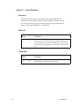
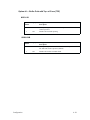
Option 20 — Double Wide Print Operation (Expanded Print Select)
Discussion
Option 20 makes it possible to print “double wide” characters. The term
“double wide” is related in an inverse manner to pitch, and generally alludes
to the width of alphanumeric characters just before the double wide feature is
invoked.
150B/L150B
Option
Number
Display
Configuration
Description
.0
20.0
Double wide on per line basis only. Enables Mode 6. Initiated by
either control code ESC SO or SO (see page 7–31). If the printer is
operating at 10 pitch when the control code is executed, printer
operation shifts to pitch 5. However, if the printer is operating at
16.7 pitch (Mode 5) when the control code is executed, printer
operation changes to 10 pitch. If control code DC4 is received
within that same line, it cancels any effect that ESC SO might have
produced. See Note.
.1
20.1
Per character width doubling through control codes (Modes 1– 5)
but excludes bit image characters. Default. Disables Mode 6.
See Note
NOTE: When executed, any one of the following codes causes the pitch to
change by one–half: (1) SO, (TEXT), LF produces a line of double
wide characters; (2) SO, (TEXT), DC4, LF produces a line at
whatever pitch is in effect at the time the line is received; or, (3)
ESC W CHR$ (1 or 49) will cause each succeeding line to have
double wide characters.
Characters are produced at the reduced pitch until: the end of the
line (printing takes place); a DC $ is received; or, in the case of ESC
W n, an ESC W CHR$ (0 or 48) is received. Printing then resumes
at the pitch rate in effect before the double wide feature was
executed. For example, a line coded A (SO) B (DC4) C LF will be
printed with “A” and “C” normal pitch and “B” double wide.
Configuration
4–9
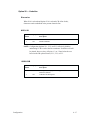
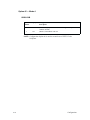
Option 21 — Vertical Dot Density
Discussion
Option 21 permits a four percent increase in vertical dot density. (The
Density Option paper feed pulley must be installed for proper operation.)
MVP/L150
Option
Number
Display
Configuration
Description
.0
21.0
Enable standard P–Series compatible vertical dot density (default).
.1
21.1
Enable increased vertical dot density (with Density Option paper
feed pulley installed).
150B/L150B
Option 21 must be set to 21.0.
4–10
Configuration
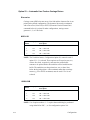
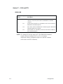
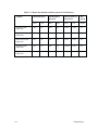
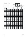
Option 22 — Insert Automatic Line Feed in Data Stream
Discussion
Normally, Option 22 is disabled. When it is enabled, a line feed is
automatically inserted into the data stream after the last character in a
character line.
MVP/L150
Option
Number
Display
Configuration
Description
.0
22.0
Disable (default). No line feed inserted. Refer to the related table in
the Programming chapter.
.1
22.1
Insert after 132nd character in Modes 001, 002 and 005 and after
165th character in Mode 003.
.2
22.2
Insert after 104th character in Modes 001, 002, and 004 and after
132nd character in Modes 003 and 005.
.3
22.3
Insert after 80th character in Modes 001 and 002, after 100th
character in Mode 003 and after 132nd character in Mode 005.
.4
22.4
Insert after 80th character in Modes 001, 002, 003 and 005.
150B/L150B
Option
Number
Display
Configuration
Description
.0
22.0
Automatic line feed inserted after 255 characters in all modes
(default).
.1
22.1
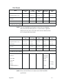
The table below shows where the automatic line feed is inserted,
depending on which mode you are in.
22.1*
22.2*
22.3*
22.4*
22.1**
Mode 1
132
104
80
80
136
Mode 2
132
104
80
80
136
Mode 3
165
132
100
80
170
Mode 4
220
132
132
80
136
Mode 5
220
176
132
80
238
* = With Configuration Option 56.0
** = With Configuration Option 56.1
Configuration
4–11
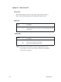
Option 23 — Automatic Line Feed on Carriage Return
Discussion
Carriage return (0DH) does not cause a line feed and the character line is not
printed in the default configuration. The character line must be terminated
with a Form Feed, Line Feed, or EVFU (Electronic Vertical Format Unit)
command before it is printed. In other configurations, carriage return
generates 1, 2, or 3 line feeds.
MVP/L150
Option
Number
Display
Configuration
Description
.0
23.0
CR = 0 line feed (default)
.1
23.1
CR = 1 line feed
.2
23.2
CR = 2 line feeds
.3
23.3
CR = 3 line feeds
NOTE: The Underline feature, Configuration Option 28, cannot be used if
option 23.1–.3 is selected. These options set CR equal to one, two,
or three line feeds, respectively, and cause the printer buffer
contents to be printed before the underlines can be loaded into the
buffer. The underlines are then printed one, two, or three lines
below the desired position. A line terminator other than a carriage
return (e.g, FF or EVFU terminator) must be used if 23.0 is not
selected.
150B/L150B
Option
Number
Display
Configuration
Description
.0
23.0
No line feed on CR (default)
.1
23.1
CR = 1 line feed
.2
23.2
CR = 2 line feeds
.3
23.3
CR = 3 line feeds
NOTE: Use of option numbers .1–.3 requires that underlining be performed
using either BS or ESC, –; n. See configuration option 28.1.
4–12
Configuration
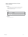
Option 24 — Inhibit Lowercase/Underline and Translate
Lowercase to Uppercase
Discussion
Normally, underlines and lowercase characters are produced in the default
configuration. When Option 24 is enabled, lowercase characters and
underlines are inhibited for all modes.
MVP/L150
Option
Number
Display
Configuration
Description
.0
24.0
Disable (default). Provides underline and lowercase.
.1
24.1
Enable. Provides uppercase only and no underlines in all modes.
150B/L150B
Option 24 must be set to 24.0.
Configuration
4–13
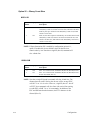
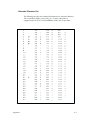
Option 25 — Binary Count Slew
MVP/L150
Option
Number
Display
Configuration
Description
.0
25.0
With Control Code 10H (binary count of 0) causes one line slew,
11H (binary count of 1) causes a two line slew, and each code increments by one up to Control Code 1FH (binary count of 15) which
causes a 16 line slew.
.1
25.1
With set, the entire sequence is shifted by one so that Control Code
10H (binary count of 0) causes a 16 line slew instead of one, 11H
causes a one line slew, and Control Code 1FH (binary count of 15)
causes a 15 line slew.
NOTE: If Paper Instruction (PI) is enabled by configuration option 61.1,
option 25 enables the user to shift the values for the line slew
control codes by one. Note that a single PI (hex 00) command will
slew a blank line.
150B/L150B
Option
Number
Display
Configuration
Description
.0
25.0
Slew 1 to 16 lines for line terminators PI (hex 00) thru PI (hex 0F).
.1
25.1
Slew 1 to 15 lines for line terminators PI (hex 00) thru PI (hex 0F).
PI (hex 00) and PI (hex 01).
NOTE: Note that a single PI (hex00) command will slew a blank line. The
distance between each P–Series plot dot row will be wrong if ESC
or SOH ’3’n or ’A’n is active. However, single PI (hex 00 – hex 0F
or EVFU slew commands will slew lines with vertical line spacing
set with ESC or S0H ’3’n or ’A’n commands. In addition to the
ESC and S0H start header characters, the ETX character is also
allowed (Hex 03).
4–14
Configuration
Option 26 — Printer On–line with Power On
Discussion
Normally when the printer is turned on, the RDY switch must be pressed
before the printer is on–line. When Option 26 is enabled, the printer is
automatically on–line when the printer is turned on.
MVP/L150
Option
Number
Display
Configuration
Description
.0
26.0
Disable (default)
.1
26.1
Enable
150B/L150B
Configuration
Option
Number
Display
Configuration
Description
.0
26.0
On–line with power on disabled (default)
.1
26.1
On–line with power on enabled.
4–15
Option 27 — Paper Out Delay
Discussion
Normally when the printer is out of paper, it will stop printing after the
current line has been printed. Option 27 allows printing to continue until the
next form feed (FF) is received or until the end of the page reaches the print
hammers (typically an additional 1.1 inch of print).
MVP/L150
Option
Number
Display
Configuration
Description
.0
27.0
Print current line only (default).
.1
27.1
Print to end of form. Permits printing of data until either the next
form feed character is received or an additional 1.1 inches (nominal) of printing or plotting has been performed, whichever comes
first.
150B/L150B
4–16
Option
Number
Display
Configuration
Description
.0
27.0
Stop immediately when out of paper (default).
.1
27.1
Print additional 1.1 inches when out of paper.
Configuration
Option 28 — Underline
Discussion
When 28.0 is selected and Option 23.0 is selected (CR=0 line feeds),
characters can be underlined in the present character line.
MVP/L150
Option
Number
Display
Configuration
Description
.0
28.0
Enable underline (default).
.1
28.1
Disable underline.
NOTE: Configuration Options 23.1, 23.2, and 23.3 effectively disables
underlining if CR is used as the line terminator. Underlines will still
be printed; however, they will print 1, 2, or 3 lines below the text
based on the CR option selected, 23.1, 23.2, or 23.3.
150B/L150B
Configuration
Option
Number
Display
Configuration
Description
.0
28.0
Leading and trailing spaces are suppressed for automatic
underline (default).
.1
28.1
Underline all blank spaces.
4–17
Option 29 — Delete Code 7F
Discussion
When a DEL (Delete) code is received, either a character from a font or a
space may be printed depending on the configuration option selected.
MVP/L150
Option
Number
Display
Configuration
Description
.0
29.0
Enable space response to DEL code (default).
.1
29.1
Disable. Prints whatever character is in the font PROM at the DEL
code address.
150B/L150B
Option
Number
Display
Configuration
Description
.0
29.0
DEL codes (7FH and FFH) are printable characters (default).
.1
29.1
DEL codes are destructive back spaces.
.2
29.2
DEL codes are ignored in data stream.
NOTE: This option is only available on printers equipped with V50. 59
DCU and MCU 20.25 (or later) firmware and primary font PROM
116043–001 or equivalent.
4–18
Configuration
Option 30 — Print or Graphics Mode at Power On
MVP/L150
Option
Number
Display
.0
30.0
Enable Mode 002 – Data Processing (default).
.1
30.1
Enable Mode 001 – Corresponding/Word Processing
.2
30.2
.3
30.3
.4
30.4
Configuration
Description
(high resolution graphics)
Enable Mode 003 – Compressed Print
(medium resolution graphics)
Enable Mode 004 – High Speed Plot
(low resolution graphics)
Enable Mode 005– Condensed Print
(medium resolution graphics)
.5
30.5
Save current mode when the printer is turned off.
NOTE: For the L150, Mode 002 should be selected when the optional
Intelligent Graphics Processor (IGP) board is being used to ensure
correctly scaled graphics.
150B/L150B
Configuration
Option
Number
Display
Configuration
Description
.0
30.0
Enable Mode 002 – Data Processing (default).
.1
30.1
Enable Mode 001 – Corresponding/Word Processing
.2
30.2
Enable Mode 003– Draft Mode
.3
30.3
Enable Mode 004 – High Speed Plot when Configuration Options
45.0 and 59.0 are enabled; Draft Mode when 45.1 and 59.0; 72.5 x
72 dpi Bar Code Mode when 59.1.
.4
30.4
Enable Mode 005– Condensed Print when when Configuration
Option 59.0 is enabled; 80 x 72 dpi Bar Code Mode when 59.1.
4–19
Options 31–41 — Control Code Assignments
Discussion
Eleven configuration options are included in this group. Each option has ten
configuration selections that can be assigned to an associated control code.
When the control code assigned to a specific configuration option appears in
the data stream, the printer will operate in response to the selection in that
option.
For example, if Configuration Option 33.4 (8 lpi) is set, code 03 Hex (ETX)
functions as Code 06 Hex (ACK), the code that causes the printer to shift
from 6 lpi to 8 lpi.
Configuration options 31 through 41 can also be used with the P–Series
programming standard for the Host Mode Control (refer to Configuration
Option 20).
MVP/L150
Option Display
Number
4–20
Option 31
Control Code Assignment – 01 Hex
.0
31.0
Host Mode Control Header 01H (SOH) (default).
.1
31.1
Host Mode Control Header 01H (SOH).
.2
31.2
Even dot plot. Code 01H (SOH) performs the same as code 04H
(EDT).
.3
31.3
Odd dot plot. Performs the same as 05H (ENQ).
.4
31.4
8 lpi. Performs the same as 06H (ACK).
.5
31.5
Elongated characters. Performs the same as 04H (EDT).
.6
31.6
Shift Out (alternate font select). Performs the same as OEH (SO).
.7
31.7
Shift In (alternate font deselect). Performs the same as OFH (SI).
.8
31.8
Ignored.
.9
31.9
Ignored.
Configuration
Option Display
Number
Option 32
Control Code Assignment – 02 Hex
.0
32.0
Ignore (default).
.1
32.1
Host Mode Control Header. Code 02H (STX) performs the same as
Code 01H (SOH).
.2
32.2
Even dot plot. Performs the same as 04H (EDT).
.3
32.3
Odd dot plot. Performs the same as 05H (ENQ).
.4
32.4
8 lpi. Performs the same as 06H (ACK).
.5
32.5
Elongated characters. Performs the same as 08H (BS).
.6
32.6
Shift Out (alternate font select). Performs the same as OEH (SO).
.7
32.7
Shift In (alternate font deselect). Performs the same as OFH (SI).
.8
32.8
Ignored.
.9
32.9
Ignored.
Option 33
Control Code Assignment – 03 Hex
.0
33.0
Ignore (default).
.1
33.1
Host Mode Control Header. Code 03H (STX) performs the same as
Code 01H (SOH).
.2
33.2
Even dot plot. Performs the same as 04H (EDT).
.3
33.3
Odd dot plot. Performs the same as 05H (ENQ).
.4
33.4
8 lpi. Performs the same as 06H (ACK).
.5
33.5
Elongated characters. Performs the same as 08H (BS).
.6
33.6
Shift Out (alternate font select). Performs the same as OEH (SO).
.7
33.7
Shift In (alternate font deselect). Performs the same as OFH (SI).
.8
33.8
Ignored.
.9
33.9
Ignored.
Option 34
Control Code Assignment – 04 Hex
.0
34.0
Even dot plot (default).
.1
34.1
Host Mode Control Header. Code 04H (STX) performs the same as
Code 01H (SOH).
.3
34.3
Odd dot plot. Performs the same as 05H (ENQ).
.4
34.4
8 lpi. Performs the same as 06H (ACK).
.5
34.5
Elongated characters. Performs the same as 08H (BS).
.6
34.6
Shift Out (alternate font select). Performs the same as OEH (SO).
.7
34.7
Shift In (alternate font deselect). Performs the same as OFH (SI).
.8
34.8
Ignored.
.9
34.9
Ignored.
Configuration
4–21
Option Display
Number
Option 35
Control Code Assignment – 05 Hex
.0
35.0
Odd dot plot (default).
.1
35.1
Host Mode Control Header. Code 05H (ENQ) performs the same as
Code 01H (SOH).
.2
35.2
Even dot plot. Performs the same as 04H (EDT).
.4
35.4
8 lpi. Performs the same as 06H (ACK).
.5
35.5
Elongated characters. Performs the same as 0EH (SO).
.6
35.6
Shift Out (alternate font select). Performs the same as OEH (SO).
.7
35.7
Shift In (alternate font deselect). Performs the same as OFH (SI).
.8
35.8
Ignored.
.9
35.9
Ignored.
Option 36
Control Code Assignment – 06 Hex
.0
36.0
8 lpi (default)
.1
36.1
Host Mode Control Header. Code 06H (ACK) performs the same as
Code 01H (SOH).
.2
36.2
Even dot plot. Performs the same as 04H (EDT).
.3
36.3
Odd dot plot. Performs the same as 05H (ENQ).
.5
36.5
Elongated characters. Performs the same as 08H (BS)
.6
36.6
Shift Out (alternate font select). Performs the same as OEH (SO).
.7
36.7
Shift In (alternate font deselect). Performs the same as OFH (SI).
.8
36.8
Ignored.
.9
36.9
Ignored.
Option 37
Control Code Assignment – 07 Hex
4–22
.0
37.0
Ignore (default).
.1
37.1
Host Mode Control Header. Code 07H (BEL) performs the same as
Code 01H (SOH).
.2
37.2
Even dot plot. Performs the same as 04H (EDT).
.3
37.3
Odd dot plot. Performs the same as 05H (ENQ).
.4
37.4
8 lpi. Performs the same as 06H (ACK).
.5
37.5
Elongated characters. Performs the same as 08H (BS).
.6
37.6
Shift Out (alternate font select). Performs the same as OEH (SO).
.7
37.7
Shift In (alternate font deselect). Performs the same as OFH (SI).
.8
37.8
Ignored.
.9
37.9
Ignored.
Configuration
Option Display
Number
Option 38
Control Code Assignment – 08 Hex
.0
38.0
Elongated characters (default).
.1
38.1
Host Mode Control Header. Code 08H (BS) performs the same as
Code 01H (SOH).
.2
38.2
Even dot plot. Performs the same as 04H (EDT)
.3
38.3
Odd dot plot. Performs the same as 05H (ENQ).
.4
38.4
8 lpi. Performs the same as 06H (ACK).
.6
38.6
Shift Out (alternate font select). Performs the same as OEH (SO).
.7
38.7
Shift In (alternate font deselect). Performs the same as OFH (SI).
.8
38.8
Ignored.
.9
38.9
Ignored.
Option 39
Control Code Assignment – 09 Hex
.0
39.0
Ignore (default).
.1
39.1
Host mode control header. Code 09h (HT) performs the same as
code 01H (SOH)
.2
39.2
Even dot plot. Performs the same as 04H (EDT).
.3
39.3
Odd dot plot. Performs the same as 05H (ENQ).
.4
39.4
8 lpi. Performs the same as 06H (ACK).
.5
39.5
Elongated characters. Performs the same as 08H (BS).
.6
39.6
Shift Out (alternate font select). Performs the same as OEH (SO).
.7
39.7
Shift In (alternate font deselect). Performs the same as OFH (SI).
.8
39.8
Ignored.
.9
39.9
Ignored.
Option 40
Control Code Assignment – 0E Hex
.0
40.0
Shift Out (alternate font select) (default).
.1
40.1
Reserved.
.2
40.2
Even dot plot. Performs the same as 04H (EDT).
.3
40.3
Odd dot plot. Performs the same as 05H (ENQ).
.4
40.4
8 lpi. Performs the same as 06H (ACK).
.5
40.5
Elongated characters. Performs the same as 08H (BS).
.7
40.7
Shift In (alternate font deselect). Performs the same as OFH (SI).
.8
40.8
Ignored.
.9
40.9
Ignored.
Configuration
4–23
Option Display
Number
4–24
Option 41
Control Code Assignment – 0F Hex
.0
41.0
Shift In (alternate font deselect). Performs the same as OFH (SI).
.1
41.1
Reserved. Host Mode Control Header. Code 0FH (SI) performs the
same as Code 01H (SOH).
.2
41.2
Even dot plot. Performs the same as 04H (EDT).
.3
41.3
Odd dot plot. Performs the same as 05H (ENQ).
.4
41.4
8 lpi. Performs the same as 06H (ACK).
.5
41.5
Elongated characters. Performs the same as 08H (BS).
.6
41.6
Shift Out (alternate font select). Performs the same as OFH (SI).
.8
41.8
Ignored.
.9
41.9
Ignored.
Configuration
Options 31–41 — Control Code Assignments
Discussion
Eleven configuration options are included in this group. When the control
code assigned to a specific configuration option appears in the data stream,
the printer will operate in response to the selection in that configuration
option. For example, if Option 31.0 is selected and ESC ! appears in the data
stream, the printer will switch to Text Dump Mode.
150B/L150B
Option
Number
Display
Option 31
Control Code Assignment – 01 Hex
.0
31.0
Escape (ESC or SOH) sequences: ESC ! for Text Dump Mode,
ESC P for Mode 1, and ESC R for Mode 2. (default)
.1
31.1
Escape (ESC or SOH) sequences: ESC ! for master print mode,
ESC P for ignored, and ESC R for ignored.
Option 32 *
Control Code Assignment – Cedilla Character Select
.0
32.0
Extended character address 128 produces a space.
.1
32.1
Extended character address 128 produces the Cedilla character
(Default).
* This configuration is available only on printers equipped with
V50.59 DCU, MCU 20.25 (or later) firmware, and primary font
PROM 116043–001 or equivalent.
Option 33
Control Code Assignment
.0
33.0
Slash zero disable (default).
.1
33.1
Slash zero enable.
Option 34
Control Code Assignment – Alternate Printronix Plot Control
.0
34.0
Enable ESC Y, even dot centers. (default)
.1
34.1
Ignore ESC Y.
Option 35
Control Code Assignment – Alternate Printronix Plot Control
.0
35.0
Enable ESC Z, odd dot centers (default).
.1
35.1
Ignore ESC Z.
Configuration
4–25
Option
Number
Display
Option 36
Control Code Assignment – Mode 1 Select
.0
36.0
Enable ESC P = Mode 1 (default) (ESC n if configuration 31.1)
.1
36.1
Ignore ESC P.
Option 37
Control Code Assignment – Mode 2 Select
.0
37.0
Enable ESC R = Mode 2 (default) (ESC r if configuration 31.1)
.1
37.1
Ignore ESC R.
Option 38
Control Code Assignment – Double High Select
.0
38.0
Enable ESC I = Double High (default) (ESC h if configuration
31.1)
.1
38.1
Ignore ESC I.
Option 39
Control Code Assignment – Mode 3 Select
.0
39.0
Enable ESC V = Mode 3 (default)
.1
39.1
Ignore ESC V.
Option 40
Control Code Assignments –– 03, 04H, 05H, 06H, 15H
.0
40.0
Codes 03H, 04H, 05H, 06H and 15H are control data (default).
.1
40.1
Codes 03H, 04H, 05H, 06H and 15H are printable characters when
ESC6 is enabled.
Option 41
Control Code Assignments –– 80H – 9FH
4–26
.0
41.0
Codes 80H – 9FH are control codes – affected by ESC 6 (default).
.1
41.1
Codes 80H – 9FH are printable characters – not affected by ESC 7.
Configuration
Option 42 — Electronic Vertical Format Unit (EVFU) Control
Discussion
The EVFU is normally fully enabled with Option 61 set to 61.0. When
Option 61 is set to 61.1, Paper Instruction (PI) may be used to disable Paper
Slew.
MVP/L150
Option
Number
Display
Configuration
Description
.0
42.0
Enable EVFU control (default).
.1
42.1
Disable EVFU using ASCII Control Code. PI EVFU control
remains enabled.
.2
42.2
Disable EVFU and interpret 10H through 1FH as printables
(requires special font PROM). PI control of EVFU remains enabled.
NOTE: 42.0 requires selection of Configuration Option 61.0; 42.1 and 42.2
require selection of Configuration Option 61.1.
150B/L150B
Configuration
Option
Number
Display
Configuration
Description
.0
42.0
Enable EVFU control (default).
.1
42.1
Disable Non–PI EVFU control; PI EVFU remains functional (see
Configuration Option 46).
4–27
Option 43 — Plotting Exit
Discussion
Normally, changing the printer from plotting to character printing requires an
extra line feed that will reset the dot row counter to zero and prevent the
upper part of the characters from possibly being truncated. Option 43 can be
configured to automatically include the line feed without being sent from the
host computer.
MVP/L150
Option
Number
Display
Configuration
Description
.0
43.0
Single line terminator moves print head to next dot row. Additional
line terminator moves print head to top of next character line and
maintains line registration within the page (default).
.1
43.1
Line terminator moves print head to top of next character dot row.
No extra line terminator is needed to avoid character truncation.
150B/L150B
4–28
Option
Number
Display
Configuration
Description
.0
43.0
Exit plot mode to top of character with extra line feed (default).
.1
43.1
Exit plot mode to top of character with no extra line feed.
Configuration
Option 44 — Buffer Print with Top–of–Form (TOF)
MVP/L150
Option
Number
Display
Configuration
Description
.0
44.0
Enable printing of buffer contents when printer is off–line and TOF
switch is pressed.
.1
44.1
Disable off–line buffer printing.
150B/L150B
Configuration
Option
Number
Display
Configuration
Description
.0
44.0
Enable printing of last line of buffer contents when printer is off–
line and TOF switch is pressed. (default)
.1
44.1
Disable off–line last line buffer flush.
4–29
Option 45 — Mode 4
150B/L150B
Option
Number
Display
Configuration
Description
.0
45.0
(Mode 4) High Speed Plot Mode with Configuration Option 59.0
enabled. (default)
.1
45.1
(Mode 4) Draft Mode with 59.0
NOTE: Configuration Option 46 is used to reconcile use of EVFU Codes
for Epson.
4–30
Configuration
Option 46 — EVFU Control with no PI
150B/L150B
Option
Number
Display
Configuration
Description
.0
46.0
Disable EVFU control with no PI and control codes: SO for double
wide, SI for mode 5 print, and BS (OEH, OFH, and 08H) for
non–destructive backspace. (default) Configuration Operation 42.x
is ignored but PI EVFU remains functional (61.1 set).
.1
46.1
Enable EVFU control with no PI and control codes: SO for alternate
font, SI for deselect alternate font, and BS (OEH, OFH, and 08H)
for elongated print.
.2
46.2
Same as 46.1 setting with the exception of the interpretation of the
ESC code [1BH]. ESC cannot be used to initiate an escape
sequence; instead use SOH code [01H] as an alternative.All control
codes 10H – 1FH, including DC2, DC4 and CAN, can be used as
EVFU channel commands.
.3
46.3
Same as 46.0 except BS (08H) is used to turn one–line vertical
elongated ON.
NOTE: 46.1 is effected by Control Code 42 and Control Codes 10H – 1FH
can be used as EVFU control commands (except for ESC code
[1BH] that is part of an escape sequence and codes DC 2 [12H],
DC4 [14H], and CAN [18H].
Configuration
4–31
Option 47 — SOH and ETX
150B/L150B
Option
Number
Display
Configuration
Description
.0
47.0
SOH (01 Hex) and ETX (03 Hex) and ESC (01, 03 and 1B Hex)
characters can all be used to initiate an EPSON like command
sequence.
.1
47.1
SOH (01 Hex) and ESC (01, and 1B Hex) can be used to initiate an
EPSON like command sequence.
.2
47.2
ESC used to initiate an EPSON like command sequence. Both SOH
and ETX characters are ignored.
.3
47.3
ETX and ESC (01, and 1B Hex) can be used to initiate an EPSON
like command sequence.
NOTE: 47.4 through 47.9 are the same as 47.2. The EPSON like command
sequence can not be initiated if 47.2, or 47.4–.9 is used in
conjunction with the Configuration Option 46.2 (the ESC character
can be used as an EVFU command).
4–32
Configuration
Option 48 — Characters Per Inch in Mode 5
150B
Option
Number
Display
Configuration
Description
.0
48.0
Mode 5 (Compressed Print Mode) prints at 100 dpi, at 16.7 cpi.
(default) The maximum line length is 220 characters per line when
Configuration Option 22.1 is enabled.
.1
48.1
Mode 5 (Compressed Print Mode) prints at 90 dpi, at 15 cpi. The
maximum line length is 198 characters per line Configuration
Option 22.1 is enabled.
NOTE: Power does not have to be cycled when this option is changed (from
48.0 to 48.1 and vice versa). Once changed, the selected pitch for
the character mode printing will remain in effect (even if power is
cycled) until a different option is selected again.
Configuration
4–33
Option 50 — Page Perforation Skip
Discussion
Use this option to avoid printing over page perforations. Option 50 allows
the bottom of the current page and the top of the next page to remain blank
for a variable vertical distance ranging from 1/2 inch to 1 inch. Perforation
skip is disabled by selecting Option 50.1 and is automatically disabled when
the EVFU is active regardless of Option 50 setting.
MVP/L150
Option
Number
Display
Configuration
Description
.0
50.0
Enable 1/2 inch skip over perforation.
.1
50.1
Disable perforation skip (default).
.2
50.2
Enable 2/3–inch skip.
.3
50.3
Enable 5/6–inch skip.
.4
50.4
Enable 1 inch skip. This function is always disabled when EVFU
memory is loaded.
150B/L150B
4–34
Option
Number
Display
Configuration
Description
.0
50.0
Enable 1/2 inch skip over perforation.
.1
50.1
Disable perforation skip. (default)
.2
50.2
Enable 2/3–inch skip over perforation.
.3
50.3
Enable 5/6–inch skip over perforation.
.4
50.4
Enable 1 inch skip over perforation. This function is always
disabled when EVFU memory is loaded.
Configuration
Option 51 — Lines Per Inch (lpi) Line Spacing
Discussion
Normally, the printer offers 6 lpi and 8 lpi spacing for modes 001, 002, 003,
and 005. Option 51 may be configured to change the 8 lpi spacing to 9 lpi or
10 lpi spacing for Modes 002 and 003.
MVP/L150
Option
Number
Display
Configuration
Description
.0
51.0
Enable 6 and 8 lines per inch (default).
.1
51.1
Enable 6 and 9 lines per inch.
.2
51.2
Enable 6 and 10 lines per inch.
150B/L150B
Configuration
Option
Number
Display
Configuration
Description
.0
51.0
Enable 6 and 8 lines per inch (default).
.1
51.1
Enable 6 and 9 lines per inch.
.2
51.2
Enable 6 and 10 lines per inch. 8, 9, or 10 lines per inch are valid in
all modes and can be controlled by an external host or by toggling
the front panel 8LPI switch.
4–35
Option 52 — Forms Length at Printer Power Up
Discussion
Forms length can be set to one of seven selectable lengths including the
default 11 inches. With Option 52 set to 52.7, any forms length between 3
inches and 24 inches (in 1/2–inch increments) can be selected with the Forms
Length (F/L) switch.
MVP/L150
Option
Number
Display
Configuration
Description
.0
52.0
Enable 11 inch form (default).
.1
52.1
Enable 3.5–inch form.
.2
52.2
Enable 5.5–inch form.
.3
52.3
Enable 8–inch form.
.4
52.4
Enable 8.5–inch form.
.5
52.5
Enable 12–inches form.
.6
52.6
Enable 14–inch form.
.7
52.7
Enable F/L switch setting; F/L switch retained when power is
cycled to the printer.
NOTE: Forms length selection is disabled when the EVFU is active and
requires that printer power be cycled to set reconfiguration.
150B/L150B
Option
Number
Display
Configuration
Description
.0
52.0
Enable 11 inch form (default).
.1
52.1
Enable 3.5–inch form.
.2
52.2
Enable 5.5–inch form.
.3
52.3
Enable 8–inch form.
.4
52.4
Enable 8.5–inch form.
.5
52.5
Enable 12–inches form.
.6
52.6
Enable 14–inch form.
.7
52.7
Enable F/L switch setting.
NOTE: Forms length selection is disabled when the EVFU is active and
requires that printer power be cycled to set reconfiguration.
4–36
Configuration
Option 54 — Line Spacing at Power up
150B
Option Display
Number
Configuration
Description
.0
54.0
6 lpi at Power up
.1
54.1
8 lpi at Power up
.2
54.2
10 lpi at Power up
NOTE: Power must be cycled when changing option 54 from .0 to .1.
Toggling the LPI switch after powerup will reset the printer to 6LPI.
Option 56 — Column Print Spacing
150B
Option Display
Number
Configuration
Configuration
Description
.0
56.0
132 column print enable (mode 5 = 16.7 cpi) (default).
.1
56.1
136 column print enable with the use of MCU 20.25 and up
(mode 5 = 17.5 characters per inch horizontally).
4–37
Option 57 — Input Buffer Size
150B
Option
Number
Display
Configuration
Description
.0
57.0
Uses all available user memory for input buffer. (default)
.1
57.1
Input buffer size is 2 lines (264 characters).
NOTE: Power must be cycled when Configuration Option 57 is selected
(from 57.0 to 57.1 and vice versa).
Option 58 — ESC DC1 Sequence
150B
Option
Number
Display
Configuration
Description
.0
58.0
ESC DC1 sequence is ignored (default)
.1
58.1
ESC DC1 sequence allowed (SCOPE line spacing n/144 inch).
Note that 58.1 will reduce the input buffer size available.
(See <ESC> or <SOH> CHR$(17).)
Option 59 — Version
150B
Option
Number
Display
Configuration
Description
.0
59.0
Standard 150B version (default)
.1
59.1
150B version for L150 board (proper MCU LM .03 or later is required for correct operation). Modes 4 and 5 are high density bar
code modes.
NOTE: For options 60 thru 99 refer to page 8–8.
4–38
Configuration
5
Graphics
Chapter Contents
Introduction . . . . . . . . . . . . . . . . . . . . . . . . . . . . . . . . . . . . . . . . . . . . . . . . . . 5–2
Raster Plotting . . . . . . . . . . . . . . . . . . . . . . . . . . . . . . . . . . . . . . . . . . . . . . . . 5–2
Raster Plot Syntax . . . . . . . . . . . . . . . . . . . . . . . . . . . . . . . . . . . . . . . . . 5–4
Print Modes for Raster Plots . . . . . . . . . . . . . . . . . . . . . . . . . . . . . . . . . . 5–5
High Resolution Raster Plot Syntax . . . . . . . . . . . . . . . . . . . . . . . . . . . . 5–6
Scaling Graphics . . . . . . . . . . . . . . . . . . . . . . . . . . . . . . . . . . . . . . . . . . . 5–6
Exiting from Raster Plot . . . . . . . . . . . . . . . . . . . . . . . . . . . . . . . . . . . . . 5–7
Bit Image Graphics . . . . . . . . . . . . . . . . . . . . . . . . . . . . . . . . . . . . . . . . . . . . 5–8
Characteristics of Bit Image Graphics . . . . . . . . . . . . . . . . . . . . . . . . . . 5–8
Plotting a Bit Image Pattern . . . . . . . . . . . . . . . . . . . . . . . . . . . . . . . . . 5–10
Bit Image Density . . . . . . . . . . . . . . . . . . . . . . . . . . . . . . . . . . . . . . . . . 5–11
Bit Image Programming Format
Bit Image Sample Program
. . . . . . . . . . . . . . . . . . . . . . . . . . . . . 5–12
. . . . . . . . . . . . . . . . . . . . . . . . . . . . . . . . . 5–13
Other Bit Image Features . . . . . . . . . . . . . . . . . . . . . . . . . . . . . . . . . . . 5–14
P–Series Plot Mode . . . . . . . . . . . . . . . . . . . . . . . . . . . . . . . . . . . . . . . . . . . 5–15
Plot Density . . . . . . . . . . . . . . . . . . . . . . . . . . . . . . . . . . . . . . . . . . . . . . 5–15
Plot Data Byte Format . . . . . . . . . . . . . . . . . . . . . . . . . . . . . . . . . . . . . 5–16
Plot Data Line Format . . . . . . . . . . . . . . . . . . . . . . . . . . . . . . . . . . . . . 5–18
Plotting Data . . . . . . . . . . . . . . . . . . . . . . . . . . . . . . . . . . . . . . . . . . . . . 5–20
Exiting P–Series Plot Mode . . . . . . . . . . . . . . . . . . . . . . . . . . . . . . . . . 5–22
Graphics
5–1
Introduction
MVP–Series printers can produce bit image graphics in two modes: Raster
Plot Mode and Bit Image Plot Mode. Both outputs are printed a dot row at a
time, from top to bottom. The major difference between the two methods is
the way the software manipulates the received data before output.
Raster plotting prints horizontal dot patterns corresponding to stored ASCII
character code true or 1 bits. In bit image plotting, the stored code prints in
vertical dot patterns because the print wires are arranged vertically.
P–Series compatible Odd/Even Dot Plot mode is only available in P–Series
printer protocol. Since plot mode can address and print any individual dot
position, it is possible to produce a variety of graphics, including bar codes,
complex curve graphs, pie and bar charts, block characters, or halftones.
To initiate special plotting features use the appropriate control sequences
described in following sections. Some control sequences require that the
software contain configuration options, coordinated with specific control
codes, before they can provide the desired printer output.
Raster Plotting
Raster plot data is sent to the printer as “printable” ASCII characters. Each
printable ASCII character has seven–bit binary code associated with it. There
are 96 printable ASCII characters (see Table 5–1), starting with SP (space)
decimal code 32, through DEL (delete) decimal code 127. Included in the set
are the ten digits (0–9), the upper and lower case alphabet (A–Z and a–z) and
the various punctuation and other characters normally available on a standard
keyboard.
Dot patterns obtained using the raster plotting feature correspond to the least
significant six bits of each seven–bit code. That is, a dot is typed for every bit
set (every “1”) in the ASCII code, except the seventh, or most significant bit.
The dot pattern progresses from left to right with the leftmost dot set by the
least significant bit (LSB).
5–2
Graphics
Graphics
5–3
OCT
040
041
042
043
044
045
046
047
050
051
052
053
054
055
056
057
060
061
062
063
064
065
066
067
070
071
072
073
074
075
076
077
BINARY
0100000
0100001
0100010
0100011
0100100
0100101
0100110
0100111
0101000
0101001
0101010
0101011
0101100
0101101
0101110
0101111
0110000
0110001
0110010
0110011
0110100
0110101
0110110
0110111
0111000
0111001
0111010
0111011
0111100
0111101
0111110
0111111
32
33
34
35
36
37
38
39
40
41
42
43
44
45
46
47
48
49
50
51
52
53
54
55
56
57
58
59
60
61
62
63
DEC
20
21
22
23
24
25
26
27
28
29
2A
2B
2C
2D
2E
2F
30
31
32
33
34
35
36
37
38
39
3A
3B
3C
3D
3E
3F
HEX
–
.
/
0
1
2
3
4
5
6
7
8
9
:
;
<
=
>
?
*
+
,
”
#
$
%
&
’
(
)
!
Space
ASCII
2 4 6 8 1012
1 3 5 7 9 11
1000000
1000001
1000010
1000011
1000100
1000101
1000110
1000111
1001000
1001001
1001010
1001011
1001100
1001101
1001110
1001111
1010000
1010001
1010010
1010011
1010100
1010101
1010110
1010111
1011000
1011001
1011010
1011011
1011100
1011101
1011110
1011111
BINARY
DEC
64
65
66
67
68
69
70
71
72
73
74
75
76
77
78
79
80
81
82
83
84
85
86
87
88
89
90
91
92
93
94
95
OCT
100
101
102
103
104
105
106
107
110
111
112
113
114
115
116
117
120
121
122
123
124
125
126
127
130
131
132
133
134
135
136
137
ASCII
40 @
41 A
42 B
43 C
44 D
45 E
46 F
47 G
48 H
49
I
4A J
4B K
4C L
4D M
4E N
4F O
50 P
51 Q
52 R
53 S
54 T
55 U
56 V
57 W
58 X
59 Y
5A Z
5B [
5C \
5D ]
5E ^
5F __
HEX
2 4 6 8 1012
1 3 5 7 9 11
Table 5–1. ASCII Dot Patterns
1100000
1100001
1100010
1100011
1100100
1100101
1100110
1100111
1101000
1101001
1101010
1101011
1101100
1101101
1101110
1101111
1110000
1110001
1110010
1110011
1110100
1110101
1110110
1110111
1111000
1111001
1111010
1111011
1111100
1111101
1111110
1111111
BINARY
140
141
142
143
144
145
146
147
150
151
152
153
154
155
156
157
160
161
162
163
164
165
166
167
170
171
172
173
174
175
176
177
OCT
96
97
98
99
100
101
102
103
104
105
106
107
108
109
110
111
112
113
114
115
116
117
118
119
120
121
122
123
124
125
126
127
DEC
60
61
62
63
64
65
66
67
68
69
6A
6B
6C
6D
6E
6F
70
71
72
73
74
75
76
77
78
79
7A
7B
7C
7D
7E
7F
HEX
Delete
}
~
r
s
t
u
v
w
x
y
z
{
h
i
j
k
l
m
n
o
p
q
‘
a
b
c
d
e
f
g
ASCII
2 4 6 8 1012
1 3 5 7 9 11
Raster Plot Syntax
The proper syntax for raster plot data is:
Control Sequence . . . ASCII Character . . . Line Terminator
All printable ASCII characters following the control sequence will be
interpreted as plot data. Raster plot data must terminated with one of the
following:
•
Line Feed command (decimal 10)
•
Vertical Tab command (decimal 11)
•
Form Feed command (decimal 12)
•
Carriage Return command (decimal 13) only if option 23.1 has been
installed. Option 23.1 causes a Line Feed to be appended in response to
the received Carriage Return automatically.
To initiate the raster plot feature, use the appropriate control sequence:
Dot
Pattern
Control
Sequence
Decimal
Value
even dot centers
EOT
4
odd dot centers
ENQ
5
even dot centers
(see page 4–25)
ESC Y
27 89
odd dot centers
(see page 4–25)
ESC Z
27 90
NOTE: A valid raster plot control sequence inserted anywhere in the data
line ahead of the line terminator will cause the entire line to be
plotted.
5–4
Graphics
Print Modes for Raster Plots
The second function switches allow you to manually select among the print
or plot modes (see Table 5–2). When manually set, the last valid mode
command received before printing will determine the line print mode. The
features listed as available in a particular mode are accessible on a per
character basis and can be combined within a line, and in some cases, within
a character matrix. However, print modes cannot be mixed on the same line.
Raster plotting is available in all modes on a per dot row basis (i.e. the entire
line must be plot) .
Special features that can be selected in each mode are included in the
“Features Available” section of Table 5–2. The letter codes are defined as
follows:
B = Bold (Double Strike)
S = Shadow (Emphasized)
U = Underlining
E = Elongated (Double High)
W = Double Wide on Per Character Basis
Table 5–2. Print Modes for Raster Plots
Mode
Panel
Display
Horiz. Pitch
(Chars/in)
Dot Density
(Dots/in)
Features
Available
1. Correspondence or
Word Processing
001
10.0
100H/96V
B, S, U, E, W
2. Data Processing
002
10.0
60H/72V
B, S, U, E, W
3. Compressed Print
003
12.5
62.5H/64V
B, S, U, E, W
4. High Speed Plot
004
N/A
50H/48V
N/A
5. Condensed Print*
005
16.7/17.5
100H/72V
B, U, E W
6. Expanded Print**
006
see page 3–6
see page 3–6
B, S, U, E
* Dependent upon configuration of option 56.
**Mode 6 operable only if option 20.0 is selected.
NOTE: All features are available in all modes with the following
exceptions: in Condensed (Mode 5), shadow print is not available;
in High Speed Plot (Mode 4), none of the features are provided; and
in Expanded Print (Mode 6), per character double wide is excluded.
Graphics
5–5
High Resolution Raster Plot Syntax
The proper command syntax for high resolution graphics is:
1) Even dot center control sequence . . . plot data . . . line terminator
followed by:
2) Odd dot center control sequence . . . plot data . . . line terminator
For Example,
EOT
(data)
ENQ
(data)
LF
LF
NOTE: When plotting even dot centers using EOT, ESC Y (line feed and
form feed commands denote end of plot data only), the paper will
not advance. When plotting odd dot centers (ENQ, ESC Z), line
feed and form feed control character denote end of plot data, and
paper will advance to the next plot line or to top–of–form.
Scaling Graphics
Scaling graphics is possible by changing print modes. Each mode has a fixed
dot density in dots per inch, which results in a different physical length for
the same raster plot data when it is plotted in different print modes. For
example, a given set of plot data that prints a one inch long line in Mode 1
(100 dots per inch) would print a line two inches long in Mode 4 (50 dots per
inch). The different length occurs because the same number of dots are
printed at different dot densities.Table 5–3 lists all the modes and their dot
densities in dots per inch.
Table 5–3. Dot Density by Mode
Mode No.
Mode
Dots/Inch
Mode selected by
ASCII code
1
Word Processing
100
ESC P
2
Data Processing
60
ESC R
3
Compressed Print
62.5
ESC V
4
High Speed Plot
50
front panel switch
5
Condensed Print
100
SI or ESC SI
6*
Expanded Print
60
SO or ESC SO
* Mode 6 operable only if Configuration Option 20.0 is selected
5–6
Graphics
Exiting from Raster Plot
To exit from raster plot, you must set Configuration Option 43.0, and send
one additional line terminator character after the last dot row is printed. An
additional line terminator will cause the paper to advance vertically to the
start of the next character line, even if the last printed dot row was between
character line boundaries.
Graphics
5–7
Bit Image Graphics
Bit image graphics are created by printing a series of vertical bit image data
bytes which represent the binary code bit pattern. This method utilizes the 1
or true bit from a binary data byte to print dot patterns. These data bytes are
actually the binary equivalent of ASCII character decimal values 0 through
255. When the data byte is rotated vertically, the result is a vertical data byte
pattern with the Most Significant Bit (MSB) at the top.
Characteristics of Bit Image Graphics
The binary data byte bit pattern for the ASCII character “A” (hex 41, decimal
65) is pictured in Figure 5–1.
•
If you rotate this data byte clockwise, the result is a vertical data byte
pattern with the the most significant bit (MSB) at the top.
•
If you print each 1 (true) bit as a dot, the result is a bit image plot of the
ASCII character “A.”
The relationship of ASCII character, decimal value, and bit image plot is
shown in Figure 5–2 .
•
You can identify the data bytes by their binary, octal, hexadecimal, or
decimal equivalents. Combined, these numeric equivalents form a bit
image pattern.
•
You can show each byte in a binary format, translate the byte to its
decimal equivalence, and use the decimal numeral (N) in a basic
command: CHR$(N).
•
You can plot bit Image patterns for any 8–bit data byte (so long as the
eighth data bit is enabled) with decimal values ranging from 0 to 255,
since bit image plotting is not limited to printable ASCII characters.
•
You can learn the the standard ASCII characters and their equivalents by
referring to the chart in Appendix A.
NOTE: Use bit image graphics in the Data Processing print mode (120 x 72
dpi). Vertical density variations in other print modes may cause
white horizontal bars or overlapping of adjacent graphics lines;
however, changing the line spacing can correct this problem. Refer
to Chapter 4 for specific density combinations.
5–8
Graphics
MSB
MSB
Figure 5–1. Vertical Data Byte Pattern
ASCII
CHARACTER
A
=
DECIMAL
VALUE
BINARY
CODE
EQUIVALENT
65
128
64
32
16
8
4
2
1
=
TO
PRINTED
BIT IMAGE
PATTERN
VERTICALLY
ROTATED DATA
BYTE
MSB
=
Figure 5–2. Bit Image Pattern from an ASCII Character
Graphics
5–9
Plotting a Bit Image Pattern
You can produce a a bit image pattern in four steps:
1.
Lay out the graphic(s) pattern you want to print, on a quadrille pad or
graph paper.
2.
Determine the decimal equivalent of each bit image data byte required
to produce your pattern (Figure 5–3).
3.
Write a program to generate the complete pattern.
4.
Enter and run the program on the host computer.
1st Bit Image Data Byte
2nd Bit Image Data Byte
Decimal
Weights
7th Bit Image Data Byte
128
64
32
16
8
4
2
1
73
36
36
73
146 255 146
Decimal
Values
Figure 5–3. Bit Image Pattern Plan
5–10
Graphics
Bit Image Density
You can print bit image graphics in different dot densities. To select dot
densities, send the appropriate control code to the datastream.
Table 5–4. Bit Image Density
Graphics
Control Code
Dot Density Mode
Result
ESC K
Single Density
Single density bit image graphics in the Data
Processing print mode (Mode 2) are printed at 60
dots per inch (dpi) horizontally and 72 dpi vertically. In the Correspondence print mode (Mode 1),
the horizontal dot density is 90 dpi and vertical dot
density is 96 dpi. In the High Speed (HS) mode
(Mode 3), horizontal dot density is 62.5 dpi and
vertical dot density is 64 dpi.
ESC L
Double Density
The Double Density mode prints up to twice the
number of dots per inch horizontally in the same
space as used for single density. The vertical dot
density remains the same as in the single density
mode. Double horizontal density requires twice the
number of input data bytes to print the same length
line as for Single Density. Printing double density
reduces the printing speed by half. If each 1 or true
bit is plotted, the result is a bit image plot of the
ASCII character “A.”
5–11
Bit Image Programming Format
The Bit Image command format is:
ESC CC(n1)(n2)DATA where:
ESC
=
the Proprinter compatible header
CC
=
K, L, ,Y or Z to select dot density
(K=single, L=double, Y=single, Z=double)
n1, n2
=
n1+ 256(n2) defines the number of data bytes
DATA
=
the dot pattern bytes
Refer to the following guidelines when using the Bit Image Programming
Format:
•
The syntax of the bit image expression must be correct.
•
The expression must include the appropriate dot density control code,
the number of bytes of data to be plotted, and the data itself.
•
The number of data bytes and the n1, n2 definition must be equal.
•
Any characters following n1 and n2 will be interpreted and plotted as
data until the n1, n2 definition is satisfied.
•
If n1 = n2 = 0, then control codes K, L, Y, or Z are ignored:
n2 = 2(700/256)
= 700 bytes of data; 2 sets of 256 with a 188 remainder
n1 = 188
= 188–byte remainder
The program statement is: ESC K(188)(2)(DATA)
NOTE: Depending on the host computer system, it may be necessary to
include a width statement within the BASIC program.
•
The maximum number of data bytes in the DATA portion of the
program statement (when using 132–column paper) varies according to
the operating mode:
At 60 dpi, Single Density
Double Density
•
5–12
=
=
792 bytes
1584 bytes
Data in excess of the right margin is discarded. If the auto line feed is
enabled, data in excess of the right margin causes a Line Feed (LF) and
continue printing on the next line.
Graphics
Bit Image Sample Program
The following sample program written in BASIC produces single density bit
image graphics of the pattern shown in Figure 5–3. The 7 data bit pattern is
repeated 40 times. The printed result of running the program is shown in
Figure 5–4.
5 WIDTH “LPT1:”,255
10 LPRINT “Single Density Bit Image Graphics”
20 LPRINT CHR$(27);“K”;CHR$(24);CHR$(1);
30 FOR N=1 TO 40
40 RESTORE
50 FOR I=1 TO 7
60 READ R
70 LPRINT CHR$(R);
80 NEXT I
90 NEXT N
100 DATA 73, 146, 36, 255, 36, 146, 73
110 LPRINT
NOTE: A detailed description of the individual bit image control codes with
examples is provided in the Programming chapter.
Figure 5–4. Sample Single Density Bit Image Graphics
Graphics
5–13
Other Bit Image Features
Bit image characters are always plotted as normal characters. Emphasized,
double strike, underlines, and doubling in width commands are ignored when
printing bit image characters. However, single density and double density bit
image may exist in the same line, and it is also possible to include text in the
same line with single density, double density, or with both. Underlines and
other normal character features may appear in a print line that also contains
bit image. Note, however, that the bit image characters are always printed
devoid of underlines or other special features.
Modes 1 and 6
In Modes 1 and 6 it is important to take precautionary steps when mixing text
and bit image data in the same line. These modes require nine steps to print
an uppercase character. A maximum of eight steps can be transmitted in bit
image. If the text is fully printed (contingent upon ESC 3 (n), ESC A (n), or
the normal power–up LF value), there will be a gap in the bit image sections
vertically. A similar situation will occur with text that includes descenders.
In this case, the last row of dots and the dot rows of descenders are cut off.
See Table 5–2 on page 5–5 for more information on available features for
each print mode.
Modes 2 and 5
In Modes 2 and 5, the gap will not occur because the uppercase characters
only occupy seven dot rows. However, the last dot row of descenders is cut
off in these modes for the same reason as explained above.
Modes 3 and 4
Bit image plotting is not available in Mode 3 or 4. However, if the feature is
called on a Mode 3 line, that line is printed in Mode 2, then the printer
returns to Mode 3.
Darker Print
Bit images can be darkened by printing over the data a second time using a
CR. For example:
ESC, K, n1, n2, DATA, (CR) ESC, K, n1, n2, DATA (LF)
5–14
Graphics
P–Series Plot Mode
P–Series compatible Odd/Even Dot Plot mode is only available in P–Series
printer protocol. Since plot mode can address and print any individual dot
position, it is possible to produce a variety of graphics, including bar codes,
complex curve graphs, pie and bar charts, block characters, or halftones.
Plot Density
Plot density refers to the number of dots per inch (dpi) printed in a single dot
row. There are two types of plot density available with P–Series Plot mode
graphics: normal density and double density.
Normal Density Plot Characteristics
Based on the mode of operation, the odd–numbered dot columns produce a
horizontal and vertical density that varies. The following table shows the
horizontal dpi and vertical dpi for the corresponding print mode. Figure 5–5
illustrates normal density dot plot.
NOTE: Different print modes cannot be mixed on the same dot row.
Print Mode
Horizontal dpi
Vertical dpi
Correspondence (NLQ)
90
96
Data Processing (DP)
60
72
High Speed (HS)
62.5
64
Barcode 145
72.5
72*
Barcode 160
80
72*
*If Configuration Option 59.0 is set to 59.1 (refer to page 4–38).
Figure 5–5. Normal Density Plot
Graphics
5–15
Double Density Plot
Two separate shuttle strokes produce a double density plot. The shuttle
strokes are controlled by an even plot command with corresponding dot data,
and an odd plot command with corresponding dot data, which allows a
maximum of 1584 dots in a single dot row at 60 dpi. The even dot plot is
sent first for control of the initial plot pattern; then the odd dot plot is sent for
control of the final dot pattern. The dots average .017 inches in diameter, and
the vertical density remains the same in normal and high density plotting.
Figure 5–6 illustrates double density plotting.
Figure 5–6. High Density Plot
Plot Data Byte Format
In P–Series Plot mode, the plot data byte format is as follows:
•
Each data byte specifies six out of twelve dot columns.
•
Bits 1 to 6 of the data byte address the odd–numbered dot columns in
the odd dot plot mode; bits 1 to 6 of the data byte address the
even–numbered dot columns in the even dot plot mode .
•
Bit 6 and/or bit 7 of the data byte must be 1 (or true) in plot mode.
•
Bit 8 of the data byte is not used in Plot mode and may be either
a 1 or 0.
•
The binary equivalent of the plot data bytes must be known to address
specific dot positions accurately.
Figure 5–7 illustrates the actual data pattern sent. Whereas Figure 5–8 shows
how the printer interprets the data for plotting; a dot is printed at the location
addressed by each of bits 1 to 6 in the data byte that is set (1 or true).
5–16
Graphics
MSB
BIT 8
BIT 7
NOT
USED
0 1 1 0 1 0 1
BIT 6
BIT 5
BIT 4
LSB
BIT 2 BIT 1
BIT 3
Figure 5–7. Actual Data Pattern Sent
EVEN DOT PLOT DATA BYTE
LSB
BIT 1
BIT 2
BIT 3
BIT 4
BIT 5
BIT 6
BIT 7
1 0 1 0 1 1 0
NOTE: BIT 6
AND/OR BIT 7
MUST BE “1”
FOR PLOT MODE
DOT COLUMN
#12 OF PREVIOUS
CHARACTER
COLUMN
2
4
6
8
10
MSB
BIT 8
NOT
USED
12
~~~ ~ ~ ~ ~~~ ~ ~ ~ ~ ~
~~~ ~ ~ ~ ~~~ ~ ~ ~ ~ ~
DOT COLUMN #1 OF
NEXT CHARACTER
COLUMN
NOTE: IN ACTUAL
PRINTING, THESE
TWO ROWS MERGE
TO PRINT ON THE
SAME ROW.
1
3
5
7
9
11
1 1 1 0 1 1 1
BIT 1
LSB
BIT 2
BIT 3
BIT 4
BIT 5
BIT 6
BIT 7
NOT
USED
BIT 8
MSB
ODD DOT PLOT DATA BYTE
Figure 5–8. P–Series Plot Data Byte Format as
Interpreted for Plotting
Graphics
5–17
Plot Data Line Format
A plot data line may contain any number of plot data bytes up to 132 bytes
(or 136 if Configuration Option 56.0 is set to 56.1; refer to page 4–37) for
horizontal dot density of 60 dpi (Data Processing mode), or 198 bytes for a
horizontal dot density of 90 dpi (Correspondence mode). When the auto line
feed is disabled, any bytes over the maximum (for the particular mode) are
lost. When the auto line feed is enabled and the maximum is exceeded, a line
feed (LF) is forced and the remaining plot data is printed as text on the next
line. The plot mode control code may occur anywhere in the line prior to the
line terminator, but plot speed may decrease if it is not at the beginning of the
line.
NOTE: P–Series graphics and printable symbols can not be intermixed on
the same line.
Normal Density Plot
For normal density plot, the plot line format contains: the odd dot plot
control code, plot data bytes, and a line terminator. The control sequence for
sending the P–Series normal density plot is as follows:
1.
Send the plot command code ENQ (05 hex).
2.
Send the plot data bytes. (Refer to Table 5–1 on page 5–3.)
3.
Send a line terminator; Line Feed or Form Feed:
a.
For a Line Feed use 0AH. A line feed plots the contents of the
buffer and advances the paper a single dot row, based on the
vertical density of the current mode. A Carriage Return (CR) may a
be used instead of the LF code, provided the carriage return has
been configured for carriage return = carriage return + line feed
(CR = CR + LF).
b.
For a Form Feed use FF, 0CH. A form feed (0C hex) plots the
contents of the buffer and advances the paper to the top of the next
form.
Regardless of which line terminator code is sent, the printer defaults to the
previously selected print mode unless further plot control codes are provided
with the data.
IMPORTANT
Failure to adhere to this format may cause unexpected results.
5–18
Graphics
Double Density Plot
For double density plot, the plot line format contains: the even dot plot
control code with plot data bytes, a line terminator to plot the data bytes, the
odd dot plot control code and a line terminator. The control sequence for
sending P–Series double density plot is as follows:
1.
Send the even dot plot control code EOT (04 hex), followed by plot data
bytes. (Refer to Table 5–1 on page 5–3.)
2.
Send a line terminator. The line terminator allows the printer to plot the
data bytes. The paper is not advanced in double density plot; the printer
will wait for the second plot command and plot data bytes.
3.
Send the odd dot plot control code ENQ (05 hex) and a second line of
data, followed by a line terminator:
a.
For a Line Feed use 0AH. A line feed plots the contents of the
buffer and advances the paper a single dot row, based on the
vertical density of the current mode. A CR (if CR = CR + LF is
configured) may also be used with the same result.
b.
For a Form Feed use 0CH. A form feed plots the data bytes and
advances the paper to the top of the next form.
Regardless of which line terminator code is sent, the printer defaults to the
previously selected print mode unless further plot control codes are provided
with the data.
IMPORTANT
Failure to adhere to this format may cause unexpected results.
Graphics
5–19
Plotting Data
P–Series Plot mode plots the image from the horizontal bit pattern.
Figure 5–9 duplicates the pattern shown in Figure 5–4 but is modified for
Odd Dot Plot. Eight dot rows are required, two characters per row, six
columns per character. (The dots required to produce the pattern are shown in
Table 5–1 on page 5–3.)
1st
CHARACTER
ODD COLUMNS
1
1
3
5
7
9 11 1
2nd
CHARACTER
ODD COLUMNS
3
5
7
1st
CHARACTER
ASCII DECIMAL
9 11
*
42
@
64
|
73
A
65
\
92
@
64
*
42
@
64
|
73
A
65
\
92
@
64
*
42
@
64
|
73
A
65
2
3
DOT
ROW
4
5
6
7
8
2nd
CHARACTER
ASCII DECIMAL
Figure 5–9. Odd Dot Plot Pattern Plan
5–20
Graphics
Programming Example with Odd Dot Plot
The following program uses the Odd Dot Plot control code to produce the
image in Figure 5–10.
10 LPRINT “Odd Dot Plot”
20 FOR I=1 TO 8
30 READ R1
40 READ R2
50 LPRINT CHR$(5);
60 FOR N=1 TO 25
70 LPRINT CHR$(R1);CHR$(R2);
80 NEXT N
90 LPRINT
100 NEXT I
110 DATA 42, 64, 73, 65, 92, 64, 42, 64, 73, 65, 92, 64, 42, 64, 73, 65
120 LPRINT
The image is printed 25 times, where an entire dot row is plotted in one
printing pass. Therefore, the first row of all 25 images is printed in one pass,
followed by the second row, etc., until all rows have been printed.
Figure 5–10. Sample Odd Dot Plot
Graphics
5–21
Exiting P–Series Plot Mode
When you want to return to the print mode from the P–Series Plot mode,
include an extra line feed in the data stream to maintain proper print line
registration relative to the last line of plot graphics. If the extra line feed is
not included, the first character line after the graphics data may be truncated,
as shown in Figure 5–11.
plot data
plot data
@ABCDEFGHIJKLMNOPQR
@ABCDEFGHIJKLMNOPQR
In this example, a text line follows plot data,
preceded by a single line terminator code.
(Text characters extend into the range of the
previously printed plot line and appear
truncated.)
This example shows a text line following
plot data, but preceded by an additional line
terminator code. (Characters are able to be
printed full–height.)
Figure 5–11. Truncated Character Line
5–22
Graphics
6
EVFU
Chapter Contents
Introduction . . . . . . . . . . . . . . . . . . . . . . . . . . . . . . . . . . . . . . . . . . . . . . . . . . 6–2
Programming EVFU Memory . . . . . . . . . . . . . . . . . . . . . . . . . . . . . . . . . . . . 6–2
Start Load Code — 6Hex . . . . . . . . . . . . . . . . . . . . . . . . . . . . . . . . . . . . 6–2
Channel Assignment
. . . . . . . . . . . . . . . . . . . . . . . . . . . . . . . . . . . . . . . 6–3
End Load Code — 6F Hex
. . . . . . . . . . . . . . . . . . . . . . . . . . . . . . . . . . 6–4
EVFU Command Codes . . . . . . . . . . . . . . . . . . . . . . . . . . . . . . . . . . . . . 6–5
EVFU Programming Example
. . . . . . . . . . . . . . . . . . . . . . . . . . . . . . . 6–5
Troubleshooting for EVFU Programming . . . . . . . . . . . . . . . . . . . . . . . . 6–7
Using EVFU . . . . . . . . . . . . . . . . . . . . . . . . . . . . . . . . . . . . . . . . . . . . . . . . . . 6–8
EVFU/IGP Execute Form Mode . . . . . . . . . . . . . . . . . . . . . . . . . . . . . . . . . . 6–9
Relative Line Slewing . . . . . . . . . . . . . . . . . . . . . . . . . . . . . . . . . . . . . . . . . . 6–9
Clearing EVFU Memory . . . . . . . . . . . . . . . . . . . . . . . . . . . . . . . . . . . . . . . 6–11
EVFU
6–1
Introduction
The Electronic Vertical Format Unit (EVFU) is a software–controlled
vertical formatter you load and operate from the host computer. When you
load the EVFU, it disables page perforation skip (Configuration Option 50)
and forms length at printer power–up (Configuration Option 52).
When you use EVFU to define print lines on a form, it increases system
efficiency because it allows the printer to slew paper to a predetermined line
with a single command.
Programming EVFU Memory
The EVFU memory is loaded with a program of line identification codes,
one for each of the lines of the form being printed. A paper instruction (PI) is
necessary with a Dataproducts interface, but is optional with a Centronics
Interface. Refer to Chapter 8 to learn differences between the Dataproducts
and Centronics interface.
Loading EFVU memory begins with a Start Load and ends with an End Load
command after the last identification code. The TOF indicator lights when
the EVFU receives the End Load command, signifying a successful program
load.
Start Load Code – 6H
The EVFU must be enabled via the control panel before the EVFU can be
loaded. While the EVFU is enabled, an E should appear on the first line of
the ONLINE/OFFLINE display. The EVFU Start Load code of 6E (hex) with
the paper instruction line (PI) high initiates the EVFU memory load routine.
Subsequent data received is considered channel assignments until the end
load code is received. The PI line is a hardware interface signal that is held
either high or low. Refer to the Interfaces chapter for PI and data line printout
information.
6–2
EVFU
Channel Assignment
All data bytes received after the Start Load code are interpreted as channel
assignment data until the End Load code is received.
A maximum of 12 channels can be assigned to one physical line on the form.
Two eight–bit data bytes (EVFU characters) are required per line. As show in
Figure 6–1, the least significant 6 bits of the first data byte are used to assign
channels 1 through 6; the least significant 6 bits of the second data byte are
used to assign channels 7 through 12. If a bit is set, the corresponding
channel is assigned. If a bit is not set, the channel is not assigned.
For example, assume 01 (hex) and 00 (hex) are the first two data bytes sent
following the Start Load code:
01 hex = 0000 0001
00 hex = 0000 0000
NOTE: This sequence results in Channel 1 being assigned to line 1 of the
form. No other channels are assigned to Line 1.
Use the following guidelines when assigning channels:
•
Channel 1 TOF must be entered before any other channel data to assign
Line 2 as the TOF. Sending channel data before assigning Channel 1 as
the TOF will cause the loading sequence to be invalid and an EVFU
memory reset.
•
The last channel loaded is assigned to the bottom–of–form.
•
Each line on the form requires two bytes. For blank lines, the two bytes
should not contain channel assignments. That is, the data bytes sent in
the load program corresponding to a blank line on the form should not
set any of bits 1 through 6.
You can assign channels up to 143 lines (285 EVFU bytes). The EVFU
ignores anything more than 286 bytes until the End Load code is received; if
572 bytes are received without an End Load code, the End Load code is
forced and the load routine is terminated.
EVFU
6–3
Line Spacing
Either 6 or 8 lpi may be used in conjunction with the EVFU. Forms length is
determined by the line density selected and is much easier to calculate if only
one line density is used throughout the form. Do not mix 6 lpi and 8 lpi on
the same form. If they are mixed, the result will be an uncertain forms length.
If mixing is unavoidable, calculate the correct forms length as follows:
a.
Count the number of lines printed and 6 lpi and divide by 6; the
result will be in inches.
b.
Count the number of lines printed at 8 lpi and divide by 8; this
result will also be in inches.
c.
Add the two results; the sum should not exceed the forms’ length.
The form’s length must be set in lines, not inches, if the EVFU is
loaded.
EVFU Memory
After printing all the forms in the run, clear the EVFU memory for the next
form program by sending a Start Load command or by momentarily turning
the printer power OFF and then ON.
End Load Code – 6F (Hex)
The EVFU End Load code is 6F (hex) with the PI line higher. Sending the
End Load code terminates the EVFU memory load routine. After the EVFU
is loaded, an L appears on the second line of the ONLINE/OFFLINE display.
If the EVFU is subsequently disabled, the load will remain valid.
If the EVFU is already loaded, an End Load code will assign the current line
as the new TOF line.
6–4
EVFU
EVFU Command Codes
The EVFU command codes (top–of–form, vertical tab, start load, and end
load) used in EVFU operation function the same way for both Centronics and
Dataproducts interfaces.
Although the EVFU command codes function the same way, there are two
major differences between the interfaces:
•
Each interface requires a different hex code that specifies a channel
number or command code.
•
The Dataproducts interface requires the presence of a paper instruction
(PI) in order for the EVFU to function correctly.
EVFU Programming Example
An example of loading a 20 line form program is shown in Figure 6–1 , and
the result of the program in shown in
NOTE: Each entry must be made for every line of form.
Filler channels are used for lines that will not be used by the print program.
Any channel except Channel 1 can be used as a filler. In Figure 6–1,
Channels 2 and 8 are used as sample fillers. Details of this procedure are
described in the following pages.
EVFU
6–5
Sample Form
Headings
Form
Line
Number
EVFU
Load
Program
SL
Hex Code
Centronics
Interface
No PI Line
1E
Hex Code
Dataproducts
Interface PI
True Line
Explanation
6E
Resets EVFU –– Forms length
defaults to current setting of FL;
enables EVFU loading.
1
CH1
10
00
1st line of form is typically defined by
CH1; interpreted as top–of–form, normally
used once per form. Form feed (14), pushing
TOF button, or CH1 slews paper to this line.
2
CH2
11
01
Any EVFU channel can be a “filler”
to occupy lines not defined for print
program use.
3
CH3
12
02
4
CH2
11
01
CH3 defines line 3 (to be printed
with NAME___).
CH2 is used as a filler.
5
CH3
12
02
6
7
CH2
CH2
11
11
01
01
RANK
8
CH4
13
03
CH4 defines line 8 (to be printed with
RANK___).
TITLE
9
CH5
14
04
10
11
12
CH2
CH2
CH2
11
11
11
01
01
01
CH5 defines line 9 (to be printed with
TITLE___).
CH2 is used as a filler.
CH2 is used as a filler
CH2 is used as a filler.
13
CH14
1D
0D
14
15
CH2
CH2
16
CH9
18
10
17
CH8
17
07
18
CH8
17
07
19
CH12
18
18
CH12 defines line 19 (to be printed
with DATE___). CH12 equals Vertical
Tab. A Vertical Tab (1B) or CH12 will
slew paper to this line.
20
CH8
17
07
CH8 is used as a filler.
EL
1F
6F
End Load defines the end of the
EVFU load program. EL turns the
TOF indicator on to indicate EVFU
loaded. TIF control is now under
EVFU control. EL also defines forms
length at 20 lines.
NAME
AGE
ADDRESS
NUMBER
DATE
11
11
01
01
CH3 defines line 5 (to be printed with)
AGE___). Any channel may define
any number of lines.
CH2 is used as a filler.
CH2 is used as a filler.
CH14 defines lines 13 (to be printed
with ADDRESS___). Channel
numbers do have to be used
sequentially.
CH2 is used as a filler.
CH2 is used as a filler.
CH9 defines line 16 (to be printed
with NUMBER___).
CH8 is used as a filler.
Any channel can be used as a filler.
CH8 is used as a filler.
Figure 6–1. EVFU Load Program
6–6
EVFU
Troubleshooting for EVFU Programming
Refer to the following guidelines when using the EVFU feature.
Printer Operation During EVFU Loading
The printer mechanism should not move during the loading of the EVFU
program. If the printer starts to print or if the paper advances, an error may
be present in the load program.
Forms Length
A Start Load code (1EH) clears the EVFU memory and allows the printer to
respond to Form Feed (FF) codes by producing the forms length selected
with Configuration Option 52.
Top–of–Form
An End Load Code (1FH) turns on the TOF indicator to signify that the
EVFU memory is loaded. If a Form Feed code (Channel 1) is issued or the
TOF switch is pressed, the paper will slew until the printer senses a
Top–of–Form (Channel 1) code.
Line Feed
When the EVFU memory is not loaded, a Vertical Tab (VT) or any EVFU
command code received through the interface causes a single line feed.
Page Perforation Skip
Loading an EVFU program automatically disables the Page Perforation Skip
(Configuration Option 50).
Paper Runaway Protection
The EVFU will slew one line if the EVFU memory program is not loaded
and the host computer issues a control code, line identification code, or slew
code as though the EVFU memory program is loaded and a channel code is
sent (but not loaded).
EVFU
6–7
Using EVFU
Once the EVFU program has been enabled and loaded, the program can be
accessed by sending the appropriate channel instruction to the printer. The
paper is slewed to the physical line on the form having the specified channel
number assigned in the EVFU memory. This is accomplished only with the
PI line held high. For a data byte to be recognized as an EVFU channel
instruction, the following criteria must be met:
•
PI line must be high.
•
Data bit 5 must be 0 (clear).
Given these two conditions, the lower 4 bits of a byte will specify the EVFU
channel number. Table 6–1 lists EVFU channels and their equivalent data
bytes.
NOTE: If the Skip–Over–Perforation feature is enabled, the printer will skip
from the BOF position to the next TOF.
Table 6–1. EVFU Channel Assignment
First Data Byte
6–8
Second Data Byte
Bit #
Channel #
Bit #
Channel #
8
X (don’t care)
8
X (don’t care)
7
X (don’t care)
7
X (don’t care)
6
6
6
12
5
5
5
11
4
4
4
10
3
3
3
9
2
2
2
8
1 (LSB)
1
1 (LSB)
7
EVFU
EVFU/IGP Execute Form Mode
To use the EVFU with the IGP, the EVFU must be loaded while the IGP is in
the Execute Form mode. Therefore, you must create and execute an empty
form with the IGP prior to using the EVFU load routine. The typical
procedure to load the EVFU while the IGP is in the Execute Form mode is as
follows.
1.
Create an empty form using the IGP Special Function Control Character
(SFCC) and Create command. Do not create any form elements and do
not use the forms length parameter.
2.
End the Create Form mode with the End command.
3.
Execute the form using the IGP Special Function Control Character
(SFCC) and Execute command. Do not use the form count or page
parameters.
4.
Enter the EVFU Start Load code.
5.
Enter the EVFU channel assignments.
6.
Enter the EVFU End Load code.
NOTE: Refer to the appropriate IGP manual for forms creation and
execution information.
Relative Line Slewing
Another method for moving paper when using the PI line is to vertically slew
a specified number of lines within the form (rather than slewing to a specific
line). To do this, three criteria must be met:
•
PI line must be high
•
Data bit 5 must be 1 (set)
•
The EVFU must be the selected Vertical Format Unit
If these criteria are met, a specific number of lines will be slewed based on
the status of data bit 1–4 as shown in Figure 6–2 . With bit 5 set and the PI
line high, this type of vertical paper motion will occur whether the EVFU
memory is loaded or not.
EVFU
6–9
Sample Form Heading Line Number
1
Hex Code
with 25.0
Hex Code
with 25.1
Explanation
0C
0C
Form Feed
11
12
2 line slew
11
12
2 line slew
2
NAME_______
3
4
AGE ________
5
6
7
RANK_______
8
12
13
3 line slew
TITLE_______
9
10
11
1 line slew
13
14
4 line slew
12
13
3 line slew
12
13
3 line slew
10
11
12
ADDRESS____
13
14
15
NUMBER_____
16
17
18
DATE________
19
20
Figure 6–2. Example of Line Slewing
6–10
EVFU
Clearing EVFU Memory
Use one of the three following actions to clear (reset) the EVFU Memory.
•
Send only the Start Load and End Load codes (no channel assignment
data).
•
Send an odd number of EVFU characters (channel assignment data)
(detected after the End Load code is received). Remember, two data
bytes are required per line.
•
Send a second Start Load code, which will result in reinitializing the
EVFU memory routine.
Table 6–2. EVFU Channel Instruction
Bits of Data Byte
Channel Selected
PI Line
8
7
6
5
4
3
2
1
1
1
X
X
X
0
0
0
0
0
2
1
X
X
X
0
0
0
0
0
3
1
X
X
X
0
0
0
0
0
4
1
X
X
X
0
0
0
0
0
5
1
X
X
X
0
0
0
0
0
6
1
X
X
X
0
0
0
0
0
7
1
X
X
X
0
0
0
0
0
8
1
X
X
X
0
0
0
0
0
9
1
X
X
X
0
0
0
0
0
10
1
X
X
X
0
0
0
0
0
11
1
X
X
X
0
0
0
0
0
12
1
X
X
X
0
0
0
0
0
X=don’t care (1 or 0)
EVFU
6–11
6–12
EVFU
7
Programming
Chapter Contents
Introduction . . . . . . . . . . . . . . . . . . . . . . . . . . . . . . . . . . . . . . . . . . . . . . . . . . 7–2
Control Codes (Quick Reference Tables) . . . . . . . . . . . . . . . . . . . . . . . . . . . 7–3
MVP/L150 Control Codes . . . . . . . . . . . . . . . . . . . . . . . . . . . . . . . . . . . . . . . 7–4
150B/ L150B Control Codes . . . . . . . . . . . . . . . . . . . . . . . . . . . . . . . . . . . . 7–27
Programming
7–1
Introduction
A typical transmission by the host computer is a data stream of ASCII
characters that includes alphanumeric characters, spaces and various symbols
and control codes. This chapter describes control codes, plotting, and host
mode controls.
7–2
Programming
Control Codes
All codes in this manual are shown in hexadecimal (Hex) notation. Appendix
A contains a complete listing of the ASCII characters in octal, decimal and
hexadecimal notation.
Table 7–1. MVP/L150 Control Codes
Code Number (Hex)
MVP/L150 Control Code
Page #
0A
Line Feed
7–4
0C
Top–of–Form/Perforation Skip
7–5
0D
Carriage Return
7–6
0E
Alternate Character Set Select
7–7
0F
Alternate Character Set Deselect
7–7
04
Even Dot Plot
7–10
05
Odd Dot Plot
7–11
06
Lines Per Inch Spacing
7–12
08
Elongated Characters
7–13
5F
Underline
7–14
Dot Density
7–15
Editing
7–17
Slewing a Specified Number of Lines
7–18
Host Mode Control
7–20
Host Mode Control Sequence Format
7–22
Host Mode Control Sequence Placement
7–23
10H–1FH
EVFU
7–26
20
Space
7–26
01–09, 0E, 0F 1B
Table 7–2. 150B/L150B Control Codes
150B Control Code
Programming
Page #
ASCII Characters
7–28
Horizontal Tab
7–36
Mode Selection from Host Computer
7–40
Underline Methods 1 & 2 (On/Off and Merged)
7–41
7–3
MVP/L150 Control Codes
0AH — Line Feed
During character printing, this control code causes the contents of the printer
buffer to be printed, followed by a one line advance of the paper to the top
row of the next character line. When multiple line feeds are sent, paper is
slewed at high speed for as many lines as line feeds sent. The effect of line
feed during plotting is discussed in the Programming chapter.
7–4
Programming
0CH — Top–of–Form/Perforation Skip
Control code 0CH causes the contents of the print buffer to be printed, and
follows up with a top–of–form or a perforation skip operation.
With Configuration Option 50
You can set the length of the Perforation Skip by using Configuration Option
50 for one of four lengths. Configuration Option 50 can also be set to disable
Perforation Skip.
NOTE: Before you power up, make sure the paper supply is properly loaded
with its top–of–form set correctly. If necessary, adjust the top–of
form.
Programming
7–5
0DH — Carriage Return
Control Code 0DH causes the logical print head to move to the left margin
without any motion or printing activity. Therefore, to initiate printing you
must send a line feed with the carriage return. If you send configuration
Option 23 for line feed on carriage return, the buffer contents will print
when a carriage return is sent.
With Configuration Option 23 and 28
If you set Configuration Option 23 to 23.0 (CR=0 line feeds), the carriage
return will not cause printing, and therefore, the underlining feature
(Configuration Option 28) will function properly. However, printing will be
delayed until you add underlines to the buffer in the desired character
positions.
When you load the buffer with characters and underlines, printing will begin
with the next line feed when sent by the host computer. This activity will
result in a line printed with the appropriate characters underlined as shown in
Figure 7–3. See page 7–14 for a complete description of the underline
function.
7–6
Programming
0EH — Alternate Character Set Select
0FH— Alternate Character Set Deselect
The printer’s controller board contains two sockets for character set PROMs.
One socket is for the primary character set PROM and the other is for the
alternate character set PROM. The primary character set PROM usually
contains standard characters while the alternate character set PROM may
contain special characters.
Alternate and Primary Characters
Alternate and primary characters can be mixed on a single line or printed
line–by–line. To select a single alternate character, you must send code 0EH
(Shift Out, alternate character set select) followed by the character code, and
code 0FH (Shift In, alternate character set deselect), through the host
computer. Several single alternate characters with a line also may be selected
this way.
Line of Alternate Characters
To select an entire line of alternate characters, you must send code 0EH to
select the alternate character set followed by a line of character codes and a
line feed through the host computer. This action will print the line, advance
the paper, and the printer will default to the primary character set.
If you select the alternate character set when the alternate character set
PROM is not installed, a blank space will be inserted each time a character
code is received. To alter this situation, the printer must receive the Shift In
code or a line feed .
Programming
7–7
04H — Even Dot Plot
05H — Odd Dot Plot
Plotting allows you to address and print any individual dot position, which
includes printing bar codes bar graphics, halftones, block characters,
schematics and complex curves. Each Plot program line results in a
horizontal print row consisting of up to 220 six–bit dot patterns, depending
on the graphics mode and plot resolution selected as shown in Table 7–3 .
Table 7–3. Number of Dot Positions in a Horizontal Plot Line
Odd or Even Dot Plot
Graphics
Mode
Data
Bytes
Dot
Positions
High Resolution Plot
Data
Bytes
Combined
Dots
Positions
Correspondence (Mode 001)
200
1320
440
2640
Data Processing (Mode 002)
132
792
264
1584
Medium Resolution (Mode
003)
137.5
825
275
1650
High Resolution (Mode 004)
159
954
318
1908
High Resolution (Mode 005)
176
1056
352
2112
The dot patterns printed correspond to the received ASCII character code
true or 1 bits. Each printable character has an eight–bit code, and patterns are
obtained using the least significant six–bits of the code. That is, a dot is
printed for every bit set (every 1) in the ASCII code except the seventh and
the eighth or most significant bit (MSB).
Figure 7–1 illustrates the actual data pattern sent. Whereas Figure 7–2 shows
how the printer interprets the data for plotting; the dot pattern progresses
from the left to right with the left dot set by the least significant bit (LSB).
The six bits are assigned to six adjacent columns (odd or even plot) within a
character position. Therefore, bits having a digital value of 1 are printed, and
any digital 0 bit is not printed.
7–8
Programming
MSB
BIT 8
BIT 7
NOT
USED
0 1 1 0 1 0 1
BIT 6
BIT 5
BIT 4
LSB
BIT 2 BIT 1
BIT 3
Figure 7–1. Actual Data Pattern Sent
EVEN DOT PLOT DATA BYTE
LSB
BIT 1
BIT 2
BIT 3
BIT 4
BIT 5
BIT 6
BIT 7
1 0 1 0 1 1 0
NOTE: BIT 6
AND/OR BIT 7
MUST BE “1”
FOR PLOT MODE
DOT COLUMN
#12 OF PREVIOUS
CHARACTER
COLUMN
2
4
6
8
10
MSB
BIT 8
NOT
USED
12
~~~ ~ ~ ~ ~~~ ~ ~ ~ ~ ~
~~~ ~ ~ ~ ~~~ ~ ~ ~ ~ ~
DOT COLUMN #1 OF
NEXT CHARACTER
COLUMN
NOTE: IN ACTUAL
PRINTING, THESE
TWO ROWS MERGE
TO PRINT ON THE
SAME ROW.
1
3
5
7
9
11
1 1 1 0 1 1 1
BIT 1
LSB
BIT 2
BIT 3
BIT 4
BIT 5
BIT 6
BIT 7
NOT
USED
BIT 8
MSB
ODD DOT PLOT DATA BYTE
Figure 7–2. Odd Dot Plot/Even Dot Plot as
Interpreted for Plotting
Programming
7–9
04 — Even Dot Plot
Even (half) dot plotting may be used to print solid lines, areas of greater
density, or to improve resolution. In even dot plotting, dots are first printed in
even numbered dot columns if plot command, 04H, is sent with the buffer
data. Paper is not advanced for that dot row. The odd column dots are
interspersed with dots printed in even numbered dot columns of that same
dot row using 05H during loading of the buffer data.
Even dot plotting is specified by the code 04H. The decoded command
NHDP inhibits the NOPP pulse from generating a RCLK pulse. This inhibits
paper motion. The even dot code and data must precede any odd dot plot
mode code and data. Paper motion occurs only after the odd dot plot shuttle
excursion, although a line feed code is used for each data transfer
termination.
Line Terminators
Even Dot Plot line terminators are 0AH (line feed), 0CH (form feed), and
0DH (Carriage Return). The printer will default to character printing after
each plot line unless you include the control code for plot within the next
data line.
Graphics and character printing can be combined on the same page, but not
on the same line. It is possible to produce special characters by plotting their
dot matrices, but this method is less efficient than creating a special character
PROM.
With Configuration Option 43
Depending on the setting of Configuration Option 43 (plot exit) when the
transition from plotting to character printing is made, adding another line
feed (LF) to the last terminator may be necessary. When you use 43.0, an
extra line feed is needed to maintain line registration throughout the page,
and to avoid the possibility of truncating the top of the first character line
after plotting. Configuration Option 43.1 does not require an extra line feed
because it is automatically included.
Figure 5–11 on page 5–22 is an example of a truncated character line
compared to a normal character line.
7–10
Programming
05H — Odd Dot Plot
For odd dot plot, the data line contains the odd dot plot control code (05H ),
the data bytes, and the terminator.
The first data byte represents the odd dots to be plotted in character column
1, and the last data byte represents the odd dots to be plotted in the highest
numbered character column used. When the terminator is read, dots print in
odd dot columns and the paper advances.
Line Terminators
Odd dot plot line terminators are 0AH (Line Feed), 0CH (form feed), and
0DH (carriage return). The printer will default to character printing after
each plot line unless you include the control code for plot within the next
data line.
Graphics and character printing can be combined on the same page, but not
on the same line. It is possible to produce special characters by plotting their
dot matrices, but this method is less efficient than creating a special character
PROM.
With Configuration Option 43
Depending on the setting of Configuration Option 43 (plot exit) when the
transition from plotting to character printing is made, adding another line
feed (LF) to the last terminator may be necessary. When you use 43.0, an
extra line feed is needed to maintain line registration throughout the page,
and to avoid the possibility of truncating the top of the first character line
after plotting. Configuration Option 43.1, does not require an extra line feed
because it is automatically included.
Refer to Figure 5–11 on page 5–22 to see an example of a truncated character
line compared to a normal character line.
Programming
7–11
06H —
Lines per Inch Spacing
Use this code to shift from 6 lpi to 8 lpi. The 8 lpi switch must be inactive. In
modes 002, 003, or 004 (not modes 001 or 005), the spacing can be changed
to 9 or 10 lpi by configuring Option 51. Control Code 06 hex must be
included in every line to be printed with 8, 9 or 10 lpi spacing or the spacing
reverts to 6 lpi. The 8 LPI indicator lights when 8, 9 or 10 lpi spacing is
selected by the code in the data stream (with the switch inactive) or when the
8 LPI switch is pressed.
7–12
Programming
08H — Elongated Characters
To form elongated characters, include Control Code 08H in the character
line, which will cause each dot row to be printed twice (except the top dot
row of uppercase characters and the bottom dot row of lowercase characters),
and keep the number of dot columns to remain the same as in standard
characters.
NOTE: Elongated characters and standard characters cannot be printed on
the same line.
Elongated characters are printed at reduced speeds with an actual line
spacing of 3 lpi and 4 lpi for the 6 lpi and 8 lpi settings, respectively.
With Forms Length
The forms length control is maintained because the control code (08H) is
used on a line–by–line basis; that is, it must appear in each line to be printed
in an elongated form. Therefore, the code may be placed anywhere in the line
preceding the line terminator.
Programming
7–13
5FH — Underline
To use the underline feature, set Configuration Option 23 to 23.0 (CR=0 line
feeds), and Configuration Option 28 to 28.0 (underline enable). Using this
setting allows for a character to be underlined because it prevents the
carriage return from producing line feeds.
When the buffer is loaded with characters and underlines, printing will begin
with the next line feed sent by the host computer. Space characters must be
specified for positions that you do not want underlined, which will print a
character line with positions underlined as shown in Figure 7–3.
Line Number
Enter
Result
1
THE PRINTRONIX PRINTER (CR)
THE PRINTRONIX PRINTER
2
SSSS_________________(LF)
THE PRINTRONIX PRINTER
S = Space (20 Hex)
LF = Line Feed (0A Hex)
CR = Carriage Return (0D Hex)*
_ = Underline (5F Hex)
NOTE: The printer must be configured for CR=CR only. If configured for a
carriage return and line feed the contents of the buffer will print
when the CR code is received.
Figure 7–3. Underline Example
7–14
Programming
Dot Density
High resolution plot combines even dot plot with odd dot plot. (Normal
plotting uses odd dot plot only.) Even dot columns are printed then odd dot
columns are printed, which is followed by a paper advance. The result is a
pattern of overlapping horizontal dots that gives the appearance of
continuous lines.
Dot densities and plot speeds vary according to the mode you select for
Configuration Option 30 or host mode control. Dot diameter approximates
.020 inch for MVP /L150 printers, and 0.013 inch for L150/L150B printers
depending on the paper stock and ribbon being used. Dot density information
for the 150B/L150B printers is listed in Chapter 5.
Table 7–4. Matrix Dot Densities and Plot Speeds
for Standard MVP Printers
Graphics
Dot Density/
Inch
Plot Resolution
Dots/Inch
Distance Between
Dot Centers
Plot
Speeds
Horz.
Vert.
Horz.
Vert.
Horz.
Vert.
In/Min
High Resolution
(Mode 001)
100
96
(100)
200
96
0.010
0.0104
8.3
Medium Resolution
(Mode 002)
60
72
(75)
120
72
0.0167
0.0139
16.7
Medium Resolution
(Mode 003)
62.5
64
(66.7)
125
64
0.016
0.0156
18.7
High Resolution
(Mode 004)
50
72
100
48
0.02
0.0208
25.0
High Resolution
(Mode 005)
80
72
(75)
100
96
0.010
0.0104
8.3
Vertical numbers in parentheses indicate vertical dots per inch using the MVP Density Option
NOTE: Plot resolution refers to the total available dot centers.
Programming
7–15
Table 7–5. Matrix Dot Densities and Plot Speeds for L150 Printers
Graphics
Dot Density/Inch
Plot Resolution
Dots/Inch
Distance Between
Dot Centers
Plot
Speeds
Horz.
Vert.
Horz.
Vert.
Horz.
Vert.
In/Min
High Resolution
(Mode 001)
100
96
200
96
0.010
0.010
8.3
Medium Resolution
(Mode 002)
60
72
120
72
0.0167
0.013
16.7
Medium Resolution
(Mode 003)
62.5
64
125
64
0.016
0.015
18.7
High Resolution
(Mode 004)
72.5
72
145
72
0.0138
0.013
25.0
High Resolution
(Mode 005)
80
72
160
72
0.0125
0.013
8.3
7–16
Programming
Editing
Any printable character in the data stream can replace printable characters or
spaces already loaded into the printer buffer. The space character (20H) is
used to skip over characters not to be replaced as shown in Figure 7–4.
NOTE: The editing function will not print the same character twice in the
same location.
Example
Enter
Result
1
ABC(CR)SAB(LF)
AAB
2
ABC(CR)SA_(LF)
AAC
3
ABC(CR)AGF(CR)LM(LF)
LMF
S = Space (20 Hex)
LF = Line Feed (0A Hex)
CR = Carriage Return (0D Hex)*
_ = Underline (5F Hex)
Figure 7–4. Editing Example
Programming
7–17
Slewing a Specified Number of Lines
To slew a specified number of lines, set Configuration Option 25 to either
25.0 or 25.1, and Configuration Options 60 and 61 to enable the use of the PI
line for EVFU control. Also, program the host computer to send a paper
instruction (PI) and a Hex code that represents the number of lines to slew.
Table 7–6 shows the relationship between the configuration, the Hex code,
and the resultant number of lines slewed. The example shown in Figure 6–2
on page 6–10 in the EVFU chapter is repeated in using line slew without
EVFU loaded.
NOTE: Set Configuration Option 25 to 25.0 for systems that require Hex
code 10 to equal a one line slew.
Table 7–6. Slew Codes with Paper Instruction Signal
(Configuration Option 60.2 and 61.1)
Paper
Instruction Code
7–18
No. of Lines Slew/Configuration Option
Hex
25.0
25.1
1
10
1
1
1
11
2
1
1
12
3
2
1
13
4
3
1
14
5
4
1
15
6
5
1
16
7
6
1
17
8
7
1
18
9
8
1
19
10
9
1
1A
11
10
1
1B
12
11
1
1C
13
12
1
1D
14
13
1
1E
15
14
1
1F
16
15
Programming
Sample
Form Heading
Line
Number
1
Hex
Hex
Code
Code
with 25.0 with 25.1
Explanation
0C
0C
Form Feed
11
12
2 line slew
11
12
2 line slew
2
NAME_______
3
4
AGE ________
5
6
7
RANK_______
8
12
13
3 line slew
TITLE_______
9
10
11
1 line slew
13
14
4 line slew
12
13
3 line slew
12
13
3 line slew
10
11
12
ADDRESS____
13
14
15
NUMBER_____
16
17
18
DATE________
19
20
Figure 7–5. Line Slew (EVFU Not Loaded)
Programming
7–19
01H–09H, 0EH, 0FH, 1BH — Host Mode Control
The Host Mode Control feature allows you to change print/plot mode on a
line–by–line basis without interrupting printer operation. Without this
feature, print/plot mode is determined by the setting of Configuration Option
30, which is loaded when the power is turned on, or manually changed when
using the control panel switches.
You can change modes on the 150B/L150B printers using host mode control
by embedding the mode change control code sequence in the data stream.
Control code sequences are interpreted according to the configuration
options resident in printer firmware, and the printer output is modified
accordingly.
Host Mode Control Feature Selection
Data stored at Configuration Option 20 determines whether the host mode
control feature is enabled or disabled and what the command sequence
recognition programming standard is. You can select either 20.1, P–Series
programming standards, or 20.2, ANSI programming standards, (refer to
Chapter 4, Configuration).
With Configuration Option 20.1
Configuration Option 20.1 enables host mode control using the P–Series
programming standard. Valid control code sequence headers (beginning
characters) are defined by option numbers contained in Configurations 31
through 41. Valid P–Series control code headers and their associated
configuration options are listed in Table 7–7. Print mode change control code
sequences must begin with the selected P–Series header.
With Configuration Option 20.2
Configuration Option 20.2 selects host mode control using the ANSI
programming standard. This standard requires all print mode change control
code sequences to begin with the Esc header (1BH).
NOTE: When Configuration Option 20.2 is selected, Electronic Vertical
Format Unit (EVFU) channel 12 (Vertical Tab 1BH) will not
operate.
7–20
Programming
Table 7–7. Configuration Options and Valid Headers
Configuration
Options
Valid Header
20.1 and 31.0
(default)
01H (SOH)
20.1 and 31.1
01H (SOH)
20.1 and 32.1
02H (STX)
20.1 and 33.1
03H (EDT)
20.1 and 34.1
04H (EDT)
20.1 and 35.1
05H (ENG)
20.1 and 36.1
06H (ACK)
20.1 and 37.1
07H (BEL)
20.1 and 38.1
08H (BS)
20.1 and 39.1
09H (HT)
20.1 and 40.1
0EH (SO)
20.1 and 41.1
0FH (SI)
20.2
1BH (ESC)
NOTE: Non–Volatile Memory can be temporarily bypassed by pressing the
CLEAR switch. No configuration data may be saved, and the
factory default is loaded.
NOTE: One or all (up to 11) of the ASCII character hexadecimal values
associated with 20.1 can be operational as a valid header.
Programming
7–21
Host Mode Control Code Sequence Format
P–Series
The P–Series (Configuration Option 20.1) control code sequence format is:
(Valid Header); [Ps q
Valid Header
[
Ps
where:
= first character (header) of a mode change control code
sequence. One of 11 hexadecimal characters can be
recognized as a valid header in accordance with
Configuration Option 31 through 41 defined in Table 7–7 .
= an ASCII “left bracket” (5BH)
= New Mode to be entered, where:
Ps = 31H, for Mode 1
Ps = 32H, for Mode 2
Ps = 33H, for Mode 3
Ps = 34H, for Mode 4
Ps = 35H, for Mode 5
q
= Control Code Sequence Terminator = 71 hex
NOTE: Do not use any spaces in the host mode control code sequence.
ANSI
The ANSI–compatible operation (Configuration Option 20.2) requires the
following Control Code sequence:
ESC [Ps q
where:
ESC
=
ASCII “Escape” (1BH)
[Ps q
=
the same as P–Series definitions
NOTE: Do not use any spaces in the ANSI host mode control code
sequence.
7–22
Programming
Host Mode Control Code Sequence Placement
A host mode control code change sequence conventionally follows a line
terminator character and applies to the data occurring before the next line
terminator character. The line terminator characters are line feed (LF), form
feed (FF), vertical tab (VT), EVFU channels (10H to 1DH), and EVFU load
codes (1EH and 1FH).
Valid Control Code Sequence
Valid Control Code sequences will be recognized anywhere in the data
stream and interpreted as applying to the data occurring between the same
two line terminators as the Control Code sequence.
The following examples are recognized as valid control code sequences. In
each case, the data occurring between the line terminators will print in the
mode specified by the control sequence.
•
(Line Terminator Previous Line) (Mode Change Control Code
Sequence) (Data) (Line Terminator).
•
(Line Terminator Previous Line)(Data) (Mode Change Control Code
Sequence)(Data) (Line Terminator).
•
(Line Terminator Previous Line)(Data) (Mode Change Control Code
Sequence)(Line Terminator).
NOTE: The initial line terminator shown in the examples above is not a
required part of any single programming line but would occur at the
end of the preceding programming line. The only requirement for
any single programming line is that the mode change Control Code
sequence must occur before the line terminator for that line.
If more than one one valid mode change control code sequence occurs
between two line terminators, the last one will take precedence.
Programming
7–23
Control Code Sequence
The printer will not return to the previous mode when a line with a mode
change is printed. The printer will always remain in the new mode until
another mode is specified. Cycling the printer power will restore the default
mode (Configuration Option 30); however, this mode may not be the same
mode prior to power cycling.
When you include the mode change control code sequence after the number
of characters (see Table 7–8), the automatic line feed is used from the
original mode (or the last mode specified within that number of characters),
and the new mode change affects only the characters after the line feed. The
effected characters are automatically wrapped around (start a new line) and
are printed in the new mode.
Table 7–8. Characters Per Line/Mode/Configuration Option
Characters Per Line/Configuration Option
Mode
22.0
22.1
22.2
22.3
22.4
1
132
132
104
80
80
2
132
132
104
80
80
3
165
165
132
100
80
4
159
132
132
132
80
5
176
132
132
132
80
NOTE: When using Configuration Option 22.0, an automatic line feed is
not inserted. The numbers given are the maximum number of
characters that can fit in a line in that mode. Additional characters
above the listed numbers overprint the beginning of the line;
however, there is one special case. A line feed will be inserted after
176 characters in Mode 5 because that is the limit of the printer
input buffer.
7–24
Programming
Invalid Control Code Sequence
An invalid control code sequence in the data steam will be treated as normal
ASCII characters. Printable characters will be printed and control characters
will be processed according to existing configuration options.
For example:
If CHR$ (4) or CHR$ (5) are used as headers and Configuration Options
24.1 or 25.1 have not been selected (default values 34.0 and 35.0 are in
effect), the line will be plotted as dot patterns rather than printed as
characters. Additional headers can be defined using Configuration
Options 31–33 and 36–41.
Programming
7–25
10H–1FH — Electronic Vertical Format Unit Codes
Refer to the EVFU chapter for programming information on the Electronic
Vertical Format Unit (EVFU).
20H — Space
The printer will leave a blank space where a space character appears (in each
character position) in a character line. Do not fill the end of a character line
with spaces unless you configure Configuration Option 22 to insert
automatic line feeds in the data stream after a particular number of
characters. When underlining (Figure 7–3), specify space characters in those
positions not to be underlined.
7–26
Programming
150B Control Codes
150B/L150B printers recognize certain ASCII characters and character
sequences as “control codes.” These codes, when placed within a program
line, cause the printer to react according to the code. There are specific
codes that can:
•
make the data in the associated data line print in a particular manner
•
do a line feed
•
move to the next tab stop
•
perform some other activity where no actual printing is involved
The control codes and associated configuration options that define specific
printer operations are contained in the Configuration chapter. See Table 7–9
if you want to use a programming language (such as BASIC) to control
printer output.
Programming
7–27
ASCII Characters
The 150B currently recognizes 56 ASCII control codes. These codes may be
single ASCII control characters (decimal numbers 00 through 31 and 127) or
the Escape character (decimal 27) followed by an ASCII character and, in
some cases, one or more additional decimal characters.
NOTE: Refer to Appendix A for more information on the extended ASCII
character set.
In BASIC
Because most programmers are familiar with BASIC, and BASIC uses
decimal numbers in LPRINT CHR$ (n) statements, all the control codes are
referenced by their decimal value. For example, if you wish to transmit a
Line Feed command to the printer in BASIC, you would use the following
syntax:
LPRINT CHR$ (10);
NOTE: 10 is the decimal value of the ASCII control character LF, or line
feed.
Table 7–9 alphabetically lists the standard set of 128 ASCII characters and
their corresponding codes in binary, octal, decimal and hexadecimal. An
extended ASCII character set is included in Appendix A.
NOTE: To view the ASCII control codes by function, refer to Appendix A.
7–28
Programming
Table 7–9. ASCII Character Control Codes
Character Name
Control Code
(ASCII)
Dec Value
CHR$(n)
ACK
(6)
Sets one line spacing to 1/8, 1/9, or 1/10
inch depending on configuration 51.X.
BS
(8)
Positions logical print head print position
one space toward left margin. See
Appendix A for the BS/CR Protocol.
CAN
(24)
• Clears print buffer in configuration 31.0
• Ignored in configuration 31.1. Refer to
Chapter 4 for details
CR
(13)
Same as Line Feed if configuration 23.1
is set (see page 4–12). 23.0 set causes
LOGICAL print head to be moved
to the left margin. See Appendix for the
BS/CR Protocol.
DLE
DLE
(16)
EVFU channel 1 (top–of–form).
DC1
DC1
(17)
EVFU channel 2.
DC2
DC2
(18)
Cancels condensed print mode (Mode 5).
See SI. EVFU channel 3.
DC3
DC3
(19)
EVFU channel 4
DC4
DC4
(20)
Cancels double wide print mode. See SO.
(Refer to ESC 6, configuration 20.X).
EVFU channel 5.
NAK
NAK
(21)
EVFU channel 6.
SYN
SYN
(22)
EVFU channel 7.
ETB
ETB
(23)
EVFU channel 8
CAN
CAN
(24)
EVFU channel 9
EM
EM
(25)
EVFU channel 10.
SUB
SUB
(26)
EVFU channel 11.
ESC
ESC
(27)
EVFU channel 12 (Vertical Tab 46.2).
ACK
Backspace
Cancel
Carriage Return
Programming
Printer Response
7–29
Character Name
Control Code
(ASCII)
Dec Value
CHR$(n)
Printer Response
FS
FS
(28)
EVFU channel 13.
GS
GS
(29)
EVFU channel 14.
RS
RS
(30)
EVFU Start load.
US
US
(31)
EVFU End load.
Delete
DEL
(127)
• Produces a spare or character in position
(127) in configuration 29.0.
• Deletes previous character sent in
configuration 29.1
• Ignored in configuration 29.2.
End of Text
EOT
(4)
Enters even dot plot mode.
(See ESC L also.) Refer to page 7–10.
Enquire
ENQ
(5)
Enters odd dot plot mode.
(See ESC K also) Refer to page 7–11.
Form Feed
FF
(12)
Advances paper to top of next page (or
“form”). Top–of–Form (TOF) and forms
length are set when paper is loaded (refer
to Chapter 2). Forms length may be
changed with control code Esc C from the
host computer or the front panel switches.
Horizontal Tab
HT
(9)
Tabs printer to next horizontal tab stop.
Refer to detailed explanation of horizontal
tabbing on page 7–36.
Line Feed
LF
(10)
Advances paper feed mechanism one line.
Line spacing is usually 1/6 inch (6 lines
per inch) unless set to 8 or 10 lpi by
control codes ESC 0 or ESC 1; or unless
ESC A (n) or ESC 3 (n) have been used to
modify the amount of paper moved in
response to a Line Feed command.
NUL
(0)
(255)
Terminates the tab setting sequence.
See page 7–36 for details of horizontal
tabs. Also part of control sequences.
Escape Codes
(see page 7–30)
NULL
7–30
Programming
Character Name
Control Code
(ASCII)
Dec Value
CHR$(n)
SI
(15)
Selects printing in condensed characters
(Mode 5, 16.7 cpi) until reset by DC2.
Same as ESC SI.
Shift Out
SO
(14)
Selects printing in double wide characters
(refer to description of ESC 6 and
Configuration 20.X) until reset by DC4 or
by printing the line. Same as ESC SO.
Vertical Tab
VT
(11)
Same as Line Feed (LF).
Activates a V.T.
ESC CAN
(27) (24)
Exit hex dump feature (option code 31.0).
(See ESC ! Configuration 31.X).
Escape, “Exclamation”
ESC!
(27) (33)
Set Hex dump feature (option code 31.0).
See ESC CAN. See alternate, ESC [
(option code 31.1).
Escape, “Equal”
ESC =
(27) (61)
Resets MSB to 0. Refer to ESC >.
Escape, minus
Decimal Number
ESC – n
(27) (45) (n)
Escape,
“Greater Than”
ESC >
(27) (62)
a) Sets MSB as 1. When this code is
input, the MSB of an 8–bit data input
following this code becomes a logic 1.
This allows computers with seven data
bits to access characters 160–255.
b) ESC > does not allow access to address
range 128–160 foreign characters. Those
can be accessed only using ESC 6.
Escape, “At”
ESC @
(27) (64)
General Printer Reset Command
a) Clear horizontal tabs to default values.
b) Clear underlines, clear emphasis, clear
double strike.
c) Reset print mode to current default.
d) Reset SO or ESC SO if pending.
e) Reset TOF to current location
f) Clears hex dump.
g) Reset line length, forms length, script,
and Data Bit 8 to power–up value.
Shift In
Printer Response
Escape Codes
Escape, “Cancel”
Programming
• n= 1 (or 49) sets underline feature.
• n=) (or 48) resets underline feature.
(Refer to page 7–41)
7–31
Character Name
Control Code
(ASCII)
Dec Value
CHR$(n)
Escape, “Pound”
ESC#
(27) (35)
Cancels the MSB (Data Bit 8) control set
by ESC = or ESC >.
Escape, “*”
ESC*
(n1) (n2)
Selects graphic density n, where:
0=60 dpi; 1=120 dpi; 2=120 dpi;
3= 150/145 dpi; 4= 80 dpi; 5=75/72.5 dpi;
6= 90 dpi; 7=160 dpi
Escape, “[mq”
ESC [mq
Escape, “Shift Out”
ESC SO
(27) (14)
Same as SO.
Escape, “Shift In”
ESC SI
(27) (15)
Same SI.
Escape, “Left Bracket”
ESC [
(27) (91)
Used with option code 31.1.
Same as ESC ! using 31.0.
Escape, “h”
ESC h
(27) (104)
Used with option code 31.1.
Same as ESC I using 31.0.
Escape, “l”
ESC l
(n)
Escape, “n”
ESC n
(27) (110)
Used with option code 31.1.
Same as ESC P using 31.0
Escape, “r”
ESC r
(27) (114)
Used with option code 31.1.
Same as ESC R using 31.0.
Escape, “x”
ESC x
(n)
ESC A (n)
(0 < n < 85)
(27) (65) (n)
Sets n/72 inch line spacing.
NOTE: Line Feed value set by ESC A (n)
does not need to be loaded by ESC 2.
Sending an ESC A (n) will cause 6 lpi.
Escape, “C”,
Dec. No. 1–127.
ESC C n
(27) (67) (n)
Sets forms length in lines, where:
1 < n < 127, TOF light turns on.
See ESC C 0 n, also.
Escape, “C”,
“zero”, number
ESC C 0 n
(27) (67)
(0) (n)
Escape, “A”,
Dec. No. 0–85
7–32
Printer Response
Selects print mode m where:
1=mode 4 . . . 5=mode 5
Sets the left margin at n.
Sets line spacing to n/144 inch.
Sets forms length in inches, where:
1 < n < 22
Programming
Character Name
Control Code
(ASCII)
Dec Value
CHR$(n)
Escape, “D” n1, n2...
n28... 1st number,
terminator, 2nd
number
ESC D
(27) (68)
(n1) (n2)
Set horizontal tabs. Refer to page 7–36 for
details on horizontal tabs.
Escape, “E”
ESC E
(27) (69)
See emphasized print mode.
Ignored if Mode 5 is active.
Escape, “F”
ESC F
(27) (70)
Reset emphasized print mode.
Escape, “G”
ESC G
(27) (71)
Set double strike mode.
Escape, “H”
ESC H
(27) (72)
Reset double strike mode.
Escape, “I”
ESC I
(27) (73)
Sets double high print feature (option code
31.0). Associated line ONLY. See alternate
ESC H (option code 31.1).
Escape, “J”
ESC J
(n)
Escape, “K”
ESC K
(27) (75)
Sets odd dot feature. All subsequent
characters in line plotted as ASCII
patterns. Plot on odd dot centers.
Refer to page 7–11.
Escape, K”
Dec. No. 1
Dec. No. 2
ESC K
(n1) (n2)
(27) (75)
(n1) (n2)
(data)
Sets Single Density Bit Image feature.
Operates in Modes 1, 2, and 5. This code
must be followed by bit image data which
establishes the bit pattern(s).
Escape, “L”
Dec. No. 1
Dec. No. 2
ESC L
(n1) (n2)
(27) (76)
(n1) (n2)
Sets Double Density Bit Image feature.
(Printer will print both even and odd dot
centers.) Operates in Modes 1, 2, and 5 in
a manner similar to ESCAPE K. A dot
pattern obtained using ESCAPE L would
have twice the dot density of one using the
ESCAPE K feature.
Escape, “M”
ESC M
Programming
Printer Response
Prints the current buffer and produces an
immediate one time line feed of n/216.
Turns elite mode ON (See Configuration
Option 59.1, 12.5 cpi)
7–33
Character Name
Control Code
(ASCII)
Dec Value
CHR$(n)
ESC N(n)
1 < n < 127
(27) (78) (n)
Escape, “O”
ESC O
(27) (79)
Disables skip over perforation
(sets skip = 0)
Escape, “P”
ESC P
(27) (80)
Sets word processing (Mode 1)
(option code 31.0). See alternate, ESC N
(option code 31.1).
Escape, “Q”
ESC Q
(n)
Escape, “R”
ESC R
(27) (82)
ESC S (n)
(27) (83) (n)
Escape, “T”
ESC T
(27) (84)
Clears superscript/subscript print
feature if set.
Escape, “V”
ESC V
(27) (86)
Set 12.5 cpi print (Mode 3). Upper case
character set and underline ONLY.
Escape, “W”
ESC W(n)
(27) (87) (n)
Escape, “N”
Dec. No. 1–127
Escape, “S”
Dec. No. (1) n=0 or
48 (2) n=1 or 49
7–34
Printer Response
a) Enables host computer to set skip over
perforation to be n lines.
b) Ignored if n is greater than forms
length.
c) Clear by ESC @.
d) Must be reset after forms length is
changed either by host computer for
from front panel.
e) Skip reset to power up value when
operator changes forms length via front
panel if host has set skip via ESC N, n.
Sets the right margin at (n).
Sets data processing (Mode 2) (option
code 31.0). See alternate, ESC r
(option code 31.1).
Sets superscript (n=0 or 48) or subscript
(n=1 or 49) feature. Operates in Modes 1,
2, 5, and 6. Superscripts and subscripts can
both occupy the same character column.
Scripted characters can be individually
specified as double wide, double struck,
or emphasized.
a) n=1 or 49; Set and hold double wide
printing. When ESC, W, 1 is asserted,
double wide isn’t cleared by printing.
b) n=0 or 48: Clear double wide printing.
Programming
Character Name
Control Code
(ASCII)
Dec Value
CHR$(n)
Escape, “Y”
ESC Y
(27) (89)
(n1) (n2)
a) Option code 34.0 causes ESC Y to act
as even dot plot. (Same as 04 code when
40.0 is set.)
b) Using 34.1, ESC Y is ignored; data
following is interpreted, literally.
Escape, “Z”
ESC Z
(27) (90)
(n1) (n2)
a) Option code 34.0 causes ESC Z to act
as odd dot plot. (Same as 05 code when
40.0 is set.)
b) Using 34.1, ESC Z is ignored;
data following is interpreted literally.
Escape, Zero
ESC 0
(27) (48)
Sets 8 lines per inch for the following
lines. Lights 8 lpi LED.
Escape, One
ESC 1
(27) (49)
Sets 10 lines per inch for the following
lines. Lights 8lpi LED.
Escape, Two
ESC 2
(27) (50)
Sets 6 lines per inch for the following
lines. Turns 8 lpi LED off.
ESC 3(n)
(0 < n < 255)
(27) (51) (n)
Sets line spacing equal to n/216 inch.
Escape, Six
ESC 6
(27) (54)
Selects decimal range 128–160 to be
printable characters until cancelled by
ESC 7.
Escape, Seven
ESC 7
(27) (55)
Selects decimal range 128–160 as control
characters.
Escape, Eight
ESC 8
Turns the paper sensor OFF.
Escape, Nine
ESC 9
Turns the paper sensor ON.
Escape, –0
ESC –0
Turns the underline mode OFF.
Escape, –1
ESC –1
Turns the underline mode ON.
Escape, –2
ESC –2
Turns the double– underline mode ON
Escape, –3
ESC –3
Turns the double–underline mode OFF
Escape, Three
Decimal Number
0–255
Programming
Printer Response
7–35
Horizontal Tab
Horizontal tabs enable you to put text at a precise column in a print line. Up
to 28 stops may be set at a time, spanning character columns 1–216.
Loading a Horizontal Tab Table
You may design and load your own horizontal tab table and tab the print
head with CHR$ (9), the decimal value of ASCII control character HT. To
make use of the custom Horizontal Tab feature you must first load a tab table
and then make calls to the table with CHR$ (9).
The proper syntax for loading the tab table is:
LPRINT ESC “D”CHR$(N2);..CHR$(128) (or CHR$(0))
where:
ESC “D”
= load HT table
CHR$(n)
= decimal numbers (1 to 216) indicating tab
stops at designated character column number.
(See “Hard Copy Considerations” in this chapter.)
CHR$(0)
or CHR$(128)
= load HT terminator
NOTE: CHR$(0) and CHR$(128) are not allowed as tab stops.
Calling a Horizontal Tab Table
After the horizontal tab table has been loaded, you may use the table by
sending CHR$ (9) to call each tab.
Example: LPRINT...DATA...CHR$ (9)DATA
7–36
Programming
Density Specifications
The following table list both the horizontal and vertical dot densities
(dots/inch) in each of the print modes as well as their character pitches in
inches:
Standard MVP
L150
136C
Mode 1
Pitch
Chars/line
100 x 96
10
132
100 x 96
10
132
100 x 96
10
132
Mode 2
Pitch
Chars/line
60 x 72
10
132
60 x 72
10
132
60 x 72
10
132
Mode 3
Pitch
Chars/line
62.5 x 64
12.5
165
62.5 x 64
12.5
165
62.5 x 64
12.5
165
Mode 4
Pitch
Chars/line
50 x 48
10/8.3
132/110
72.5 x 72
12.1/12.5
159/165
50 x 48
10/8.3
136/113
Mode 5
Pitch
Chars/line
100 x 72
16.7
220
80 x 72
13.3
175
105x 72
17.5
238
Mode 1 =
Mode 2 =
Mode 3 =
Mode 4 =
=
=
Mode 5 =
=
=
Standard =
L150
=
136 C =
Programming
Correspondence or Word Processing
Data Processing
Draft Mode
High Speed plot; 8.33 cpi (45.0 and 59.0)
Draft Mode; 10 cpi (45.1 and 59.0)
High Density Bar Code (12.5 cpi with MCU 20.25) or
(12.1 cpi with LM .0x MCU)
Condensed Print; 16.7 cpi (59.0 and 56.0)
Condensed Print; 17.5 cpi (59.0 and 56.1)
High Density Barcode; 13.3 cpi (59.1)
Normal Mode (59.0 and 56.0)
Barcode Mode (59.1)
136–column print mode( 56.1 and 59.0)
7–37
Hard Copy Considerations
Follow these guidelines for using horizontal tabs:
•
Tabs must be set in ascending order.
•
The maximum decimal value of n(i) will depend on the mode in use.
NOTE: Be sure proper width will accommodate tab settings.
•
If the length of STRING (i) after TAB (i) is greater than the spaces
between TAB (i) and TAB (i+1) then STRING (i+1) will be printed at
TAB (i+2).
•
Any illegal loading sequence will be ignored and the default condition
shall be applied when HT is called.
•
If there are more calls than there are TABs then the first string
corresponding to the FIRST EXTRA CALL will be printed one space
after the last string corresponding to the last tab in the table.
•
Horizontal tab and automatic underline features may be used in the
same line. If underline is entered before the call for tab then the tab is
underlined also. If the call for tab is entered before the underline
sequence, then only the text assigned by the tab will be underlined.
•
When changing modes after setting tabs:
•
7–38
a.
Auto LF feature not set: a call to a tab stop beyond the physical line
will cause wraparound of the character line. For example, tab stop
set to 144 in Mode 5 (16.7 cpi) current print mode is Mode 2 where
column 132 is maximum.
b.
If auto line feed is set, a call to a tab location beyond the physical
line length will cause the auto Line Feed to act, and the data at the
tab stop will appear on the next line.
At power–up the HT table is set as shown in Table 7–10.
Programming
Table 7–10. Horizontal Tabs at Power–up
TAB#
TAB position
MODE
(Mode 1 & 2)
(Mode 3)
(Mode 5)
0
8
1
16
.
.
.
2
24
.
.
.
3
32
.
.
.
4
40
.
.
.
5
48
.
.
.
6
56
.
.
.
7
64
.
.
.
8
72
.
.
.
9
80
.
.
.
10
88
.
.
.
11
96
.
.
.
12
104
.
.
.
13
112
.
.
.
14
120
.
.
.
15
136
.
.
16
144
.
.
17
152
.
.
18
160
.
.
19
168
.
.
20
176
.
21
184
.
22
192
.
23
200
.
24
208
.
25
216
.
Programming
7–39
Mode Selection from Host Computer
Mode selection from the host computer allows you to change the printing
mode of the printer via the I/O, by using appropriate control sequences. All
print modes can be selected from the front panel as well as from power –up,
via Configuration 30.X.
If the mode is set from the front panel, the first print line will set the print
mode back to either to: (1) the power–up default mode, or (2) Mode 5; if
Mode 5 was asserted when the front panel was used to change the mode.
Sequences and Other Modes
Mode
5
Character/Mode
Condensed
CPI
16.7
Set/Select
Reset
ESC, SI, SI
(Hex 1B, OF;
DEC Set17, 15)
DC2
(see Note)
3
Compressed
12.5; high speed
ESC V
Selecting
another print
mode
2
Data Processing
10; high speed
ESC R
Selecting
another print
mode
1
Word Processing
10; high speed
ESC P
Selecting
another print
mode
NOTE: DC2 resets mode 5. Printer stays in Mode 5 until another mode is
selected or DC 2 is sent. When the DC2 is sent, the printer will reset
to the power–up mode as set by configuration 30.X if no other mode
is asserted.
7–40
Programming
Underline — Methods 1 & 2
The printer will automatically generate the underline as required by the
particular character line transmitted. Leading and trailing spaces are not
underlined. Use the following guidelines and see Figure 7–6:
•
Underlines start and stop on the normal character boundary and are
permissible at 6 or 8 lpi.
•
The ESC sequences can be repeated multiple times within a line and
can, by themselves, constitute a printable line comprised of only
underlines (assuming configuration 28.1 is set).
•
Spaces will be underlined as normal printable character, if they are
preceded by an ESC – 1 sequence. Any incorrect sequence will be
ignored.
•
The Underline mode set by ESC – n is not cleared by performing a print
or paper movement, but stays in effect until the ESC–0 sequence is
received or the printer is powered off.
Method 1 (On/Off)
On
Underlines are turned on by the control sequence ESC – 1 (or hex string 1B,
2D, 01) where the character 1 in the ESC sequence is the second character
(SOH) in the ASCII character chart (see Appendix A).
NOTE: Hex 31 can replace hex 01.
Off
Underlines are turned off by the control sequence ESC – 0 (or hex string 1B,
2D, 00) where the character 0 in the ESC sequence is the first character
(NUL) in the ASCII character chart (see Appendix A).
NOTE: Hex 30 can replace hex 01.
Programming
7–41
1
2 3
TEXT: ****now****is****the****LF
4
****time***for*all****LF
KEY:
* = space
1 = Underline turned ON.
2 = Underline turned OFF.
3 = Underline turned ON. Result: Now
4 = Underline turned OFF. Result: time
is
for
the
all
Figure 7–6. Leading and Trailing Spaces
7–42
Programming
Method 2 (Merged)
Underlining can also be accomplished by sending the sequence:
TEXT, CR, SP/UL, line terminator. Underlining is on a per character basis.
Example:
Sent: A B C D E, CR, SP, UL, SP, SP, CR, LF
Printed: ABCDE
•
It isn’t necessary to match the length of the string between the text and
underlines, and spaces beyond that required to position the underlines as
desired.
•
Reversing the order of the string to: SP/UL, CR, TEXT, CR, LF is
permissible following the same positioning requirement.
Compatibility with Other Features
Programming
•
Configuration 28.0: leading and trailing spaces are not underlined
(reference (ESC) (–) (n) only).
•
Configuration 28.1: everything following (ESC) (–) (CHR$) 1 or 49 is
underlined.
•
Underlines are functional with all features except plot and any lpi
spacing such as 10 lpi in which there are no available dot rows for the
underlines.
•
Underlines are functional with automatic LF; configuration 23.X.23.O
must be set (CR = no Line Feed) in order to use CR as a flag for
underlining.
7–43
7–44
Programming
8
Interfaces
Chapter Contents
Introduction . . . . . . . . . . . . . . . . . . . . . . . . . . . . . . . . . . . . . . . . . . . . . . . . . . 8–2
Centronics and Dataproducts Interface Characteristics . . . . . . . . . . . . . . 8–2
Centronics Interface . . . . . . . . . . . . . . . . . . . . . . . . . . . . . . . . . . . . . . . . . . . . 8–3
Dataproducts Interface . . . . . . . . . . . . . . . . . . . . . . . . . . . . . . . . . . . . . . . . . . 8–5
Interface Configuration Options 60–99 . . . . . . . . . . . . . . . . . . . . . . . . . . . . . 8–8
Switching Interfaces . . . . . . . . . . . . . . . . . . . . . . . . . . . . . . . . . . . . . . . . . . . 8–26
Interfaces
8–1
Introduction
The MVP–Series printer interfaces are logically and electronically
compatible with the Centronics and Dataproducts interfaces. The Centronics
and Dataproducts interfaces allow the parallel transfer of 8 data bits, one byte
at a time. The switch from one interface to the other requires a simple change
of the printer’s input/output (I/O) cable, terminating resistors, and
Configuration Option 66 (see “Switching Interfaces” on page 8–26 ).
Centronics and Dataproducts Interface Characteristics
Centronics and Dataproducts interface circuit characteristics are as follows.
Interface Cable
The cable must not exceed 40 feet and must allow the transmission of signals
having standard TTL logic level (0.0V to +0.5V low and +2.4V to +5.25V
high). Use shielded cable with the shield grounded to minimize electrical
noise.
Logic Levels
0.0V to +0.5V low; +2.4V to +5.25V high.
Receivers
TTL 74LS14 with a 1000–ohm pull–up terminating resistor pack in location
18C (Centronics) or optional 220–ohm and 330–ohm pull–up/pull–down
terminating resistor packs in locations 18C and 17C, respectively
(Dataproducts).
Drivers
TTL 7407 with a 1000–ohm pull–up terminating resistor pack in location
15C (Centronics or Dataproducts).
Terminating Resistors
The Centronics parallel interface requires that 1000–ohm resistor packs be
installed at Parallel Controller PCBA coordinates 15C and 18C see
Figure 8–5. Typical circuits using the resistors are shown in Figure 8–6. The
Dataproducts Interface requires the 220–ohm resistor pak at coordinates 18C
and a 300–ohm pack at coordinates 17C. A 1000–ohm pack is installed at
location 15C. A resistor pack is not required with the Serial Controller
PCBA.
Logic Configuration
Standard positive true; Option Code 63 is configurable to negative true logic.
8–2
Interfaces
Centronics Interface
The Centronics (standard) interface transfers parallel data bytes at a rate of
up to 200,000 characters per second. The interface requires an I/O cable
assembly with an Amphenol compatible connector (Printronix P/N
110376–001) as shown in Figure 8–1, connected to the properly terminated
Parallel Controller PCBA at P4. Configuration Option 66 must be set to 66.0
Figure 8–1. Centronics Connector
Figure 8–2 illustrates the Centronics interface timing sequence. Data transfer
is initiated when the host computer places a data byte on the data lines. After
a delay of at least 50 ns, the host computer issues DATA STROBE to latch
the data byte into the receiver latches. DATA STROBE must be at least 100
ns in duration. Normally, the printer responds with a 4 µs ACKNOWLEDGE
pulse and BUSY. If Configuration Option 65.1 is selected, BUSY will be
suppressed until the host computer sends a line terminator control code byte
(FF, LF, or EVFU). Table 8–1 describes the Centronics interface signals and
pin assignments and Table 8–2 describes the Dataproducts interface signals
and pin assignments.
Figure 8–2. Centronics Interface Timing Sequence
Interfaces
8–3
Table 8–1. Centronics Interface Signals and Pin Assignments Input Signals
Connector
Input Signals
Description
PIN
RETURN
DATA STROBE
A low active true pulse (at least 100 ns duration) from the host computer to clock data into the printer. Data lines must stabilize for at
least 50 ns before DATA STROBE is sent.
1
19
DATA LINE 1
DATA LINE 2
DATA LINE 3
DATA LINE 4
DATA LINE 5
DATA LINE 6
DATA LINE 7
DATA LINE 8
Eight high active lines from the host computer forming a character
byte or a Control Code byte.
2
3
4
5
6
7
8
9
20
21
22
23
24
25
26
27
PAPER
INSTRUCTION
Enables EVFU control (when clocked into printer by DATA
STROBE). Effective only when Configuration Option 60 is set 60.2
and 61 is set to 61.1. DATA STROBE timing is the same as for data
lines.
15
14
Refer to Configuration Option 60, Section 5.6, for DATA LINE 8
control.
Table 8–2. Centronics Interface Signals and Pin Assignments Output Signals
Connector
Output Signal
Description
PIN
RETURN
ACKNLG
Low active pulse from the printer to indicate the printer is ready for the
next data transfer.
10
28
SLCT
A high active level (when PE level is low) from the printer to indicate the
printer is ready to receive data and the RDY switch has been activated.
13
32
N/A
PE
A high active level from the printer to indicate a check (CHK) condition.
12
N/A
BUSY
A high active level from the printer to indicate a check (CHK) condition.
11
29
5 VOLT
TEST
Supplies +5V (at one Ampere) output for powering a Printronix Test
Exerciser (Exerciser not required for the L150)>
18
N/A
CHASSIS
GROUND
Connections for a cable shield.
17
N/A
SPARE
Not Used.
30
31
32
34
34
36
8–4
Interfaces
Dataproducts Interface
The optional Dataproducts interface transfers parallel data at a rate of up to
400,000 characters per second. It requires an I/O cable assembly with
Winchester–compatible connector (Printronix P/N 110628–001) as shown in
Figure 8–3 or an Amphenol–compatible connector (Printronix P/N 110638–
001) connected to the properly terminated Parallel Controller PCBA at P4.
Configuration Option 66 must be set to 66.1
Figure 8–3. Dataproducts Connector
Figure 8–4 illustrates the Dataproducts interface timing sequence. The printer
signals status to the host computer by putting a high on the DATA
REQUEST line along with READY and ONLINE. The host computer places
a data byte on the input lines. After the data has stabilized for at least 50 ns,
the computer issues DATA STROBE to latch the data byte into the receiver
latches. DATA STROBE also causes DATA REQUEST to go low, and must
go low again itself at least 50 ns before the data byte is withdrawn by the
host computer. At least 1 us later, the printer will return the DATA
REQUEST line to a high state and again be ready to accept data.
Figure 8–4. Dataproducts Interface Timing Sequence
Interfaces
8–5
Table 8–3. Dataproducts Interface Signals and Pin Assignments Input Signals
Amphenol
Winchester
Input Signals
Description
Pin
Return
Pin
Return
DATA STROBE
A high active pulse (requires Configuration Option
62.1) of at least 100 ns duration sent by the host
computer to indicate data is ready to be sent to the
printer.
38
37
j
m
PAPER
INSTRUCTION
(PI)
A high active level from the host computer clocked
into the printer with the same timing as the data
lines. Effective only when Configuration Option 60
is set to 60.2 and 61 is set to 61.1
30
14
p
s
DATA LINE 1
DATA LINE 2
DATA LINE 3
DATA LINE 4
DATA LINE 5
DATA LINE 6
DATA LINE 7
DATA LINE 8
Eight high active level (low active under
Configuration Option 63.1) from the host computer
that form a character byte or control code byte.
19
20
1
41
34
43
36
28
3
4
2
40
18
42
35
44
B
F
L
R
V
Z
n
h,u
D
J
N
T
X
b
k
e,w
PARITY
The state of this line is host computer controlled.
The total number of active levels on the PARITY
line plus the eight DATA Lines is an even number
(even parity check) or an odd number (odd parity
check).
29
13
NOTE: Refer to Configuration Option 60, Section 5.6 for DATA LINE 8
control.
8–6
Interfaces
Table 8–4. Dataproducts Interface Signals and Pin Assignments (Continued)
Output Signals
Amphenol
Output Signals
Winchester
Description
Pin
Return
Pin
Return
READY/PE
A high active level from the printer to indicate:
1. AC power and DC voltages present.
2. Printer paper loaded properly.
3. Printer is not in a CHK condition.
22
6
CC
EE
ONLINE
High active level from the printer to indicate:
1. The READY line is true.
2. RDY switch on the operator control panel
has been activated.
21
5
y
AA
DATA REQUEST
(demand line)
High active level from the printer to
synchronize host computer data transmission
with printer timing. High level indicates printer
data request. The signal remains high for as
much as 250 ns after DATA STROBE signal is
received then the DATA REQUEST drops to
low (false) and remains low until the data is
stored in the printer’s buffer.
23
7
E
C
GROUND
Connections for cable shield.
39
M,f,
FF
VERIFICATION
Jumper between two pins on the interface
connector enables verification that the
interface connector is seated correctly
46
45
x
y
TEST
Supplies +5V (at one Ampere) output for the
Printronix test exerciser. (Exerciser not needed
for L150.)
12
HH
Interfaces
8–7
Interface Configuration Options 60–99
The final step in the printer/host computer interfacing procedure requires
obtaining a configuration printout (self–test 00.1) to ensure that the correct
interface control configuration options (addresses 60–99) are set. Addresses
60–66 apply to the parallel (Centronics and Dataproducts) interfaces. Refer
to Chapter 4 for reconfiguration procedures.
Table 8–5. Quick Reference Table for Interface Configuration Options 60 –99
Configuration
Number
8–8
Printer
Type
Configuration Option
Page #
60
All
Data Line 8 with Parallel Interface
8–9
61
All
Paper Instruction with Parallel Interface
8–10
62
All
Data Strobe Line Polarity with Parallel Interface
8–11
63
All
Data Lines and Response Line Logic Polarity with Parallel Interface
8–12
64
All
Reserved for Future Use
65
All
Busy
8–13
66
All
Parallel Interface Selection
8–14
67–69
All
Reserved for Future Use
70
MVP/L150
Serial Interface/Protocol Selection
8–15
71
MVP/L150
Serial Data Transfer Baud Rate
8–16
72
MVP/L150
Data Word Interface Configuration
8–17
73
MVP/L150
Transmitted Data Polarity
8–18
74
MVP/L150
Request to Send (RTS)
8–19
75
MVP/L150
Clear to Send (CTS) and Carrier Detect (CD)
8–20
76
MVP/L150
Data Set Ready (DSR–RS–232 pin 6)
8–21
77
MVP/L150
Reverse Channel (RC)
8–22
78
MVP/L150
Data Terminal Ready (DTR)
8–23
79
MVP/L150
XON Buffer Level Threshold
8–24
80
MVP/L150
XOFF Buffer Level Threshold
8–24
81
MVP/L150
Current Loop Out
8–24
82
MVP/L150
Protocol Character Assignment – XON or ACK
8–25
83
MVP/L150
Protocol Character Assignment – XOFF or NAK
8–25
84
MVP/L150
Protocol Character Assignment – ETX
8–25
85–89
All
Reserved for Future Serial Interface Options
90–99
All
Reserved for Future Options
Interfaces
Option 60 — Data Line 8 with Parallel Interface
MVP/L150
Option 60 allows the use of parallel interface Data Line 8 to select the
Alternate Font PROM or for paper instruction (PI).
Option
Number
Display
Configuration
Description
.0
60.0
Disable or not used (default).
.1
60.1
Enable Data Line 8 to select alternate font.
.2
60.2
Enable Data Line 8 for paper instruction.
150B/L150B
Interfaces
Option
Number
Display
Configuration
Description
.0
60.0
Disable Data Line 8.
.1
60.1
Enable Data Line 8 (allows access to characters (128–255).
8–9
Option 61 — Paper Instruction with Parallel Interface
MVP/L150
The paper instruction (PI) is normally not used but may be enabled for use in
controlling the EVFU.
Option
Number
Display
Configuration
Description
.0
61.0
Disable or not used (default).
.1
61.1
Enable use of paper instruction line for EVFU control.
150B/L150B
8–10
Option
Number
Display
Configuration
Description
.0
61.0
Disable (default).
.1
61.1
Enable use of paper instruction line for EVFU control.
Interfaces
Option 62 — Data Strobe Line Polarity with Parallel Interface
MVP/L150
Data Strobe is normally a low active (negative true) signal but may be
configured to be high active (positive true).
Option
Number
Display
Configuration
Description
.0
62.0
Enable negative data strobe line polarity transition (default).
.1
62.1
Enable positive data strobe line polarity transition.
150B/L150B
Interfaces
Option
Number
Display
Configuration
Description
.0
62.0
Enable negative data strobe line polarity transition (default).
.1
62.1
Enable positive data strobe line polarity transition.
8–11
Option 63 — Data Lines and Response Line Logic Polarity with
Parallel Interface
MVP/L150
Lines in Option 63 are normally high active (positive true) but they may be
configured to low active (negative true) signals; Selected/Online, PE, and
Data Request are affected. Acknowledge, used in the Centronics interface,
remains low active.
Option
Number
Display
Configuration
Description
.0
63.0
Enable high active data and responsive lines logic polarity (default).
.1
63.1
Enable low active data and responsive lines logic polarity.
NOTE: Option 64 is reserved for future use.
150B/L150B
8–12
Option
Number
Display
Configuration
Description
.0
63.0
Enable high active data and responsive lines logic polarity (default).
.1
63.1
Enable low active data and responsive lines logic polarity.
Interfaces
Option 65 — Busy Line
MVP/L150
A high active busy line normally indicates the printer cannot receive data
(the printer is advancing paper or is offline). The configuration may be set
for active busy with any print line terminator including CR=0 line feeds.
Option
Number
Display
Configuration
Description
.0
65.0
Enable character by character handshake mode using busy (default).
.1
65.1
Enable active Busy with print line terminator control code.
150B/L150B
Option 65 must be set to 65.0.
Interfaces
8–13
Option 66 — Parallel Interface Selection
MVP/L150
The default sets the Centronics interface; however, this option also may be
set for the Dataproducts interface.
Option Display
Number
Configuration
Description
.0
66.0
Enable Centronics compatible parallel interface (default).
.1
66.1
Enable Dataproducts compatible parallel interface.
150B/L150B
Option Display
Number
8–14
Configuration
Description
.0
66.0
Enable Centronics compatible parallel interface (default).
.1
66.1
Enable Dataproducts compatible parallel interface.
Interfaces
Option 70 — Serial Interface/ Protocol Selection
Two fundamental protocols, basic RS–232 and current loop are available for
transferring data across the interface. Three character–oriented protocols can
be used in combination with the fundamental protocols: XON/XOFF,
ACK/NAK, and ETX/ACK.
Interfaces
Option
Number
Display
Configuration
Description
.0
70.0
RS–232–Basic (default)
.1
70.1
RS–232 with XON/XOFF Protocol
.2
70.2
RS–232 with ETX/ACK Protocol
.3
70.3
RS–232 with ACK/NAK Protocol
.4
70.4
Current loop – busy open loop
.5
70.5
Current loop – busy closed loop
.6
70.6
Current loop with XON/XOFF Protocol
.7
70.7
Current loop with ETX/ACK Protocol
.8
70.8
Current loop with ACK/NAK Protocol
8–15
Option 71 — Serial Data Transfer and Baud Rate
Ten selectable baud rates for transferring data across the interface are
possible. Nine are generated within the system, while the tenth can be
implemented external to the system. Although ordinary RS–232 transmission
can be done at all available rates, do not use current loop at rates exceeding
4800.
Option
Number
Display
Configuration
Description
.0
71.0
9600 Baud (1 stop bit) or not used if RS–232 not installed (default).
.1
71.1
110 (2 stop bits).
.2
71.2
150 (1 stop bit).
.3
71.3
300 (1 stop bit).
.4
71.4
600 (1 stop bit).
.5
71.5
1200 (1 stop bit).
.6
71.6
2400 (1 stop bit).
.7
71.7
4800 (1 stop bit).
.8
71.8
19200 (1 stop bit).
.9
71.9
External (1 stop bit).
NOTE: Stop bits apply only to printer transmitted data.
8–16
Interfaces
Option 72 — Data Word Interface Configuration
Serial data bytes are transferred in a format that consists of a single start bit
followed by 7 or 8 data bits, one parity bit, and 1 or 2 stop bits. The basic
data word is 7 bits long. If the 8th bit is used, it can be used either to choose
between the Primary Font PROM or the Alternate Font PROM on the Serial
Controller PCBA, or to identify a Paper Instruction (PI) for the EVFU. The
8th bit can also be ignored. The parity bit is used for either even parity or odd
parity or it can be ignored. Any parity error detected by the printer will cause
a question mark (?) to be printed for that character.
Interfaces
Option
Number
Display
Configuration
Description
.0
72.0
Enable 7 bit data word – no parity check (default).
.1
72.1
Enable 7 bit data word with even parity check.
.2
72.2
Enable 7 bit data word with odd parity check.
.3
72.3
Enable 8th bit as data bit for font selection – no parity check.
.4
72.4
Enable 8th bit as data bit for font selection with even parity check.
.5
72.5
Enable 8th bit as data bit for font selection with odd parity check.
.6
72.6
Enable 8th bit as paper instruction – no parity check.
.7
72.7
Enable 8th bit as paper instruction with even parity check.
.8
72.8
Enable 8th bit as paper instruction with odd parity check.
.9
72.9
Ignore 8th bit – no parity check.
8–17
Option 73 — Transmitted Data Polarity
Logic polarity is normally positive true, but can be reconfigured to be
negative true.
8–18
Option
Number
Display
Configuration
Description
.0
73.0
Enable normal logic (default).
.1
73.1
Enable interverted polarity logic.
Interfaces
Option 74 — Request to Send (RTS)
Interface line pin 4 can be made true when the printer status is :
ONLINE AND BUFFER ALMOST EMPTY (READY)
OFFLINE OR BUFFER ALMOST FULL (BUSY)
ONLINE (NO REGARD FOR BAE)
Interfaces
Option
Number
Display
Configuration
Description
.0
74.0
Enable ON condition when printer is online and buffer is not full
(Ready) (default).
.1
74.1
Enable ON condition when printer is offline or buffer is full (Busy).
.2
74.2
Enable ON condition when printer is online.
.3
74.3
Enable always ON.
.4
74.4
Enable always OFF.
8–19
Option 75 — Clear to Send (CTS) and Carrier Detect (CD)
Two interface lines normally ignored by the printer. When a modem is used,
they are configured to avoid being ignored. CTS (pin 5) informs the printer
that the host computer is ready to receive data. CD (pin 8) allows the printer
to send data.
8–20
Option
Number
Display
Configuration
Description
.0
75.0
Disable (default).
.1
75.1
Enable – (CTS must be ON for data transmission from the printer
and CD must be ON for printer to receive data.
Interfaces
Option 76 — Data Set Ready (DSR–RS–232 pin 6)
Interface line pin 6 is normally ignored by the printer. When configured to
not to be ignored, the printer firmware must verify that this interface line is
true before the printer accepts the data.
Interfaces
Option
Number
Display
Configuration
Description
.0
76.0
Disable (default).
.1
76.1
Enable (DSR must be ON for printer to receive data).
8–21
Option 77 — Reverse Channel (RC)
The Reverse Channel Interface line (pins 11 and 14) is disabled by default.
The RC interface line can be made high true when the printer status is:
ONLINE AND BUFFER ALMOST EMPTY (READY)
OFFLINE OR BUFFER ALMOST FULL (BUSY)
8–22
Option
Number
Display
Configuration
Description
.0
77.0
Disable (default).
.1
77.1
Enable ON condition when printer is online and buffer is not full
(Ready).
.2
77.2
Enable ON condition when printer is offline or buffer is full (Busy).
.3
77.3
Enable low ON (true) when printer is offline and buffer is not full.
Interfaces
Option 78 — Data Terminal Ready (DTR)
Interface line pin 20 can be made true when the printer status is:
ONLINE AND BUFFER ALMOST EMPTY (READY)
OFFLINE OR BUFFER ALMOST FULL (BUSY)
In addition, the DTR interface line can be held always ON (true) or always
OFF (false).
Interfaces
Option
Number
Display
Configuration
Description
.0
78.0
Enable ON condition when printer is online and buffer is not full
(Ready) (default).
.1
78.1
Enable ON condition when printer is offline or buffer is full (Busy).
.2
78.2
Enable always ON.
.3
78.3
Enable always OFF.
8–23
Option 79 — XON Buffer Level Threshold
Allows a choice of two Buffer Almost Empty (BAE) thresholds.
Option
Number
Display
Configuration
Description
.0
79.0
0% of installed buffer (default).
.1
79.1
25% of installed buffer.
Option 80 — XOFF Buffer Level Threshold
Allows a choice of two Buffer Almost Full (BAF) thresholds.
Option
Number
Display
Configuration
Description
.0
80.0
75% of installed buffer (default).
.1
80.1
85% of installed buffer.
Option 81 — Current Loop Out
Disables the current loop or allows a choice between internal or external
current source.
8–24
Option
Number
Display
Configuration
Description
.0
81.0
Disable (default).
.1
81.1
Enable Internal Current source (active).
.2
81.2
Enable External Current source (passive).
Interfaces
NOTE: The Configuration Option Format on the digital panel changes for
Configuration Options 82 through 84. After first indicating the
address selected (82, 83, or 84), the left digit changes to zero and
the two right digits display a two digit decimal Configuration suffix.
82 — Protocol Character Assignment – XON or ACK
Defines the decimal code equivalent for XON or ACK. The default value is
17, but any two digit code between 00 and 99 may be used. Used in
conjunction with Configuration Option 83.
Display
82.17
Configuration Description
XON or ACK (default).
83 — Protocol Character Assignment – XOFF or NAK
Defines the decimal code equivalent for XOFF or NAK. The default value is
19, but any two digit code between 00 and 99 may be used.
Display
83.19
Configuration Description
XOFF or NAK (default).
84 — Protocol Character Assignment – ETX
Defines the decimal code equivalent for ETX. The default value is 03, but
any two digit code between 00 and 99 may be used.
Display
84.03
Interfaces
Configuration Description
ETX (default)
8–25
Switching Interfaces
As previously mentioned, switching from one interface to the other requires a
simple change of the printer’s input/output (I/O) cable, terminating resistors,
and Configuration Option 66 (refer to Switching Interfaces in this chapter).
Interface Cables
The Centronics or Dataproducts interface cable must not exceed 40 feet in
length and must allow the transmission of signals having standard TTL logic
levels (0.0V to +0.5 low and +2.4V to +5.25V high). For minimum electrical
noise, use shielded cable and ground the shield.
Terminating Resistors
The Centronics parallel interface requires that 1000–ohm resistor packs be
installed at Parallel Controller PCBA coordinates 15 C and 18C as shown in
Figure 8–5. Typical circuits using the resistors are shown in Figure 8–6.
The Dataproducts interface requires the 220–ohm resistor pack at coordinates
18C and a 330–ohm pack at coordinates 17C. A 1000–ohm pack is installed
at location 15C.
8–26
Interfaces
Figure 8–5. Controller PCBA
Figure 8–6. Interface Receiver and Driver Circuits
Interfaces
8–27
8–28
Interfaces
A
Appendix
Character Sets and Control Codes
A–1
ASCII Character Set
B7
B6
BITS
KEY
0
0
B5
1
B4 B3 B2 B1
1 0
1
1
ESC
OCTAL
DECIMAL
HEX
33
27
1B
ASCII CHARACTER
B7
B6
0
0
B5
BITS
0
0
0
0
1
1
0
1
0
1
0
1
1
0
0
1
1
1
1
1
0
1
COLUMN
0
B4 B3 B2 B1 ROW
1
NUL
0
0
0
SOH
1
1
1
0 0 0 0
0
0 0 0 1
1
0 0 1 0
2
STX
2
2
2
0 0 1 1
3
ETX
3
3
3
0 1 0 0
4
EOT
0 1 0 1
5
0 1 1 0
2
DLE
20
16
10
DC1
21
17
11
(XON)
3
SP
40
32
20
!
41
33
21
4
0
60
48
30
1
61
49
31
5
6
@
100
64
40
P
120
80
50
A
101
65
41
Q
121
81
51
a
7
140
96
60
p
160
112
70
141
97
61
q
161
113
71
22
18
12
”
42
34
22
2
62
50
32
B
102
66
42
R
122
82
52
b
142
98
62
r
162
114
72
(XOFF)
23
19
13
#
43
35
23
3
63
51
33
C
103
67
43
S
123
83
53
c
143
99
63
s
163
115
73
4
4
4
DC4
24
20
14
$
44
36
24
4
64
52
34
D
104
68
44
T
124
84
54
d
144
100
64
t
164
116
74
ENQ
5
5
5
NAK
25
21
15
%
45
37
25
5
65
53
35
E
105
69
45
U
125
85
55
e
145
101
65
u
165
117
75
6
ACK
6
6
6
SYN
26
22
16
&
46
38
26
6
66
54
36
F
106
70
46
V
126
86
56
f
146
102
66
v
166
118
76
0 1 1 1
7
BEL
7
7
7
ETB
27
23
17
47
39
27
7
67
55
37
G
107
71
47
W
127
87
57
g
147
103
67
w
167
119
77
1 0 0 0
8
BS
10
8
8
CAN
30
24
18
(
50
40
28
8
70
56
38
H
110
72
48
X
130
88
58
h
150
104
68
x
170
120
78
1 0 0 1
9
HT
11
9
9
EM
31
25
19
)
51
41
29
9
71
57
39
I
111
73
49
Y
131
89
59
i
151
105
69
y
171
121
79
1 0 1 0
10
LF
12
10
0A
SUB
32
26
1A
*
52
42
2A
:
72
58
3A
J
112
74
4A
Z
132
90
5A
j
152
106
6A
z
172
122
7A
1 0 1 1
11
VT
13
11
0B
ESC
33
27
1B
+
53
43
2B
;
73
59
3B
K
113
75
4B
[
133
91
5B
k
153
107
6B
{
173
123
7B
1 1 0 0
12
FF
14
12
0C
FS
34
28
1C
54
44
2C
<
74
60
3C
L
114
76
4C
\
134
92
5C
l
154
108
6C
|
174
124
7C
15
1 1 0 1
13
CR
1 1 1 0
14
SO
16
14
0E
SI
17
15
0F
1 1 1 1
A–2
15
13
0D
DC2
DC3
GS
35
29
1D
RS
36
30
1E
US
37
31
1F
’
,
–
55
45
2D
.
56
46
2E
/
57
47
2F
=
75
61
3D
>
76
62
3E
?
77
63
3F
M
115
77
4D
N
116
78
4E
O
117
79
4F
]
^
_
135
93
5D
m
155
109
6D
}
175
125
7D
136
94
5E
n
156
110
6E
~
176
126
7E
137
95
5F
o
157
111
6F
DEL
177
127
7F
Appendix
Extended Character Set
The following lists show the extended font character set. Note that Character
128 is available in Modes 1 and 6 only, or 1, 2, and 6 if the printer is
equipped with V50.59 DCU and font PROM 116043–001 or equivalent.
Appendix
A–3
A–4
Appendix
BS/CR Protocol
Protocol After Receiving a CR or BS Character*
Old Character
New Character
Resulting Character
1. space
space
space
2. character
space
character
3. space
character
new character
4. character
underline
old char + UL
5. underline
character
new char + UL
6. character
character
new character
7. bit image
space
bit image
8. space
bit image
bit image
9. character
bit image
bit image
10. underline
bit image
bit image
11. bit image
character
character
Attributing Conditions
1. normal
normal
normal
2. dbl wide
(Conf. 20.1)
normal
normal
3. dbl strike
normal
normal
4. emp
normal
normal
5. normal
dbl wide
(Conf. 20.1)
wide
6. normal
dbl strike
dbl strike
7. normal
emp
emp
8. not underlined
underlined
underlined
9. script
normal
normal
10. normal
script
script
11. super/subscript
sub/superscript
sub + super **
* If character following CR or BS matches character string before CR or BS,
it will be printed in double strike to emulate second pass over print (bold).
** This feature enables subscript and superscript placement on the same
character column.
Appendix
A–5
ASCII Control Codes by Function
Print Width Commands
Control Code
(ASCII)
Character
Name
Dec Value
CHR$(n)
EOT
End of Text
(4)
ENQ
Enquire
(5)
DC2
DC2
(18)
DC4
DC4
(20)
Shift In
(15)
Shift Out
(14)
SI
SO
ESC P
Escape, “P”
(27) (80)
ESC R
Escape, “R”
(27) (82)
ESC V
Escape, “V”
(27) (86)
ESC W(n)
Escape, “W”
(27) (87) (n)
ESC Y
Escape, “Y”
(27) (89)
(n1) (n2)
ESC Z
Escape, “Z”
(27) (90)
(n1) (n2)
ESC n
Escape, “n”
(27) (110)
ESC r
Escape, “r”
(27) (114)
ESC M
Escape, “M”
ESC [mq
A–6
Escape,
“[mq”
Appendix
Print Quality Commands
Control Code
(ASCII)
Dec Value
CHR$(n)
ESC E
Escape, “E”
(27) (69)
ESC F
Escape, “F”
(27) (70)
ESC G
Escape, “G”
(27) (71)
ESC H
Escape, “H”
(27) (72)
ESC S (n)
ESC T
Appendix
Character Name
Escape, “S”
Dec. No. (1) n=0 or
48 (2) n=1 or 49
(27) (83) (n)
Escape, “T”
(27) (84)
ESC SO
Escape, Shift Out
(27) (14)
ESC SI
Escape, Shift In
(27) (15)
ESC–n
Escape, minus
Decimal Number
(27) (45) (n)
ESC –0
Escape, –0
ESC –1
Escape, –1
ESC –2
Escape, –2
ESC –3
Escape, –3
A–7
Selecting Print Modes
Control Code
(ASCII)
Character Name
Dec Value
CHR$(n)
ESC @
Escape, “At”
(27) (64)
ESC I
Escape, “I”
(27) (73)
ESC h
Escape, “h”
(27) (104)
Escape, Cancel
(27) (24)
ESC!
Escape, Exclamation
(27) (33)
ESC [
Escape, “Left Bracket”
(27) (91)
ESC CAN
Graphic Modes
Control Code
(ASCII)
A–8
Character Name
Dec Value
CHR$(n)
ESC K
Escape, “K”
(27) (75)
ESC K
(n1) (n2)
Escape, K”
Dec. No. 1
Dec. No. 2
(27) (75)
(n1) (n2)
(data)
ESC L
(n1) (n2)
Escape, “L”
Dec. No. 1
Dec. No. 2
(27) (76)
(n1) (n2)
ESC*
Escape, “*”
(n1) (n2)
Appendix
Special Printer Features
Control Code
(ASCII)
BS
Character Name
Dec Value
CHR$(n)
Backspace
(8)
CAN
Cancel
(24)
DEL
Delete
(127)
ESC 6
Escape, Six
(27) (54)
ESC >
Escape,
Greater Than
(27) (62)
ESC 7
Escape, Seven
(27) (55)
ESC =
Escape, Equal
(27) (61)
ESC#
Escape, Pound
(27) (35)
Forms Control Commands
Control Code
(ASCII)
Appendix
Character Name
Dec Value
CHR$(n)
CR
Carriage Return
(13)
FF
Form Feed
(12)
ESC C n
Escape, “C”,
Dec. No. 1–127.
(27) (67) (n)
ESC C 0 n
Escape, “C”,
“zero”, number
(27) (67)
(0) (n)
ESC N(n)
1 < n < 127
Escape, “N”
Dec. No. 1–127
(27) (78) (n)
ESC O
Escape, “O”
ESC 8
Escape, Eight
ESC 9
Escape, Nine
(27) (79)
A–9
Paper Feed Commands
Control Code
(ASCII)
ESC A (n)
(0 < n < 85)
LF
Escape, “A”,
Dec. No. 0–85
Line Feed
Dec Value
CHR$(n)
(27) (65) (n)
(10)
ESC 0
Escape, Zero
(27) (48)
ESC 1
Escape, One
(27) (49)
ESC 2
Escape, Two
(27) (50)
ESC 3(n)
(0 < n < 255)
ACK
ESC 3(n)
(0 < n < 255)
A–10
Character Name
Escape, Three
Decimal Number
0–255
ACK
Escape, Three
Decimal Number
0–255
(27) (51) (n)
(6)
(27) (51) (n)
ESC J
Escape, “J”
(n)
ESC x
Escape, “x”
(n)
Appendix
Formatting Commands
Control Code
(ASCII)
Dec Value
CHR$(n)
HT
Horizontal Tab
(9)
VT
Vertical Tab
(11)
ESC D
Appendix
Character Name
Escape, “D” n1, n2...
(27) (68)
(n1) (n2)
NUL
NULL
(0)
(255)
DLE
DLE
(16)
DC1
DC1
(17)
DC2
DC2
(18)
DC3
DC3
(19)
DC4
DC4
(20)
NAK
NAK
(21)
SYN
SYN
(22)
ETB
ETB
(23)
CAN
CAN
(24)
EM
EM
(25)
SUB
SUB
(26)
ESC
ESC
(27)
FS
FS
(28)
GS
GS
(29)
RS
RS
(30)
US
US
(31)
A–11
9
Routine Service and Diagnostics
Chapter Contents
Introduction . . . . . . . . . . . . . . . . . . . . . . . . . . . . . . . . . . . . . . . . . . . . . . . . . . 9–2
Cleaning Requirements . . . . . . . . . . . . . . . . . . . . . . . . . . . . . . . . . . . . . . . . . 9–2
Before Cleaning . . . . . . . . . . . . . . . . . . . . . . . . . . . . . . . . . . . . . . . . . . . . 9–3
Cleaning the Printer . . . . . . . . . . . . . . . . . . . . . . . . . . . . . . . . . . . . . . . . . 9–5
Moving the Printer . . . . . . . . . . . . . . . . . . . . . . . . . . . . . . . . . . . . . . . . . . 9–7
Reconnecting the Cables . . . . . . . . . . . . . . . . . . . . . . . . . . . . . . . . . . . . . 9–8
Corrective Maintenance . . . . . . . . . . . . . . . . . . . . . . . . . . . . . . . . . . . . . . . . . 9–9
Self–Tests . . . . . . . . . . . . . . . . . . . . . . . . . . . . . . . . . . . . . . . . . . . . . . . . . . . 9–10
Self–Test Procedure . . . . . . . . . . . . . . . . . . . . . . . . . . . . . . . . . . . . . . . 9–10
Self–Test Configuration . . . . . . . . . . . . . . . . . . . . . . . . . . . . . . . . . . . . 9–12
Routine Service and Diagnostics
9–1
Introduction
The MVP–Series printers require little maintenance beyond general cleaning.
However, to avoid maintenance problems, periodically remove excess paper
chaff, and dust from the ribbon and paper paths. Be aware that there will be
times when it will be necessary to determine whether a service call is
necessary. In these instances, refer to the “Corrective Maintenance” section
of this chapter for information on how to locate and diagnose printer
problems. If you are unable to locate the problem even after cleaning,
contact your authorized service representative.
Cleaning Requirements
Periodic cleaning ensures efficient operation and clear print quality. Clean
the printer every three months or after every 250 hours of operation,
whichever occurs first. If the printer is located in a dusty area or is used for
heavy duty printing, clean it more often. Any service other than periodic
cleaning must be done only by an authorized service representative.
– WARNING –
Unplug the printer before cleaning the printer.
General External Cleaning
Clean the outside of the cabinet with a soft, lint–free cloth and mild detergent
soap. (Dishwashing liquid works well.) Do not use abrasive powders or
chemical solvents. Clean the windows with plain water or mild window
cleaner. Always apply the cleaning solution to the cloth; never pour cleaning
solution directly onto the printer.
General Internal Cleaning
Over time, particles of paper and ink accumulate inside impact printers. This
is normal. Paper dust and ink build–up must be periodically removed to
avoid degraded print quality. Most paper dust accumulates around the ends of
the platen and ribbon path.
9–2
Routine Service and Diagnostics
Before Cleaning
Before cleaning the printer, turn the printer off and unplug the power cord.
Unload the paper (page 3–12), and perform the following steps. (refer to the
maintenance manual for further assistance).
NOTE: If you must move the printer, follow instructions in the next section
on Moving the Printer.
1.
Fully raise the forms thickness adjustment lever.
FormsThickness
Adjustment
Lever
2.
Unlatch both ribbon spools, and carefully lift them off the hub. Raise the
ribbon out of the ribbon path.
Ribbon Path
3.
Remove the shuttle cover by grasping the cover on both sides. Lift it up
at the rear, while gently sliding it backward and off the shuttle.
Routine Service and Diagnostics
9–3
4.
Remove the hammer bank assembly cover as follows:
a.
Lift and hold the shuttle locking knob as far as it will go.
Metal
Strips
Black Knob
b.
Grasp the hammer bank cover assembly carefully and tilt it up from
the front, away from you.
45°
c.
Pull the cover assembly upward so that it clears the small retaining
pins of the hammer tips; pull the cover assembly clear from the
magnets.
Metal Strips
Hammer Tips
9–4
Routine Service and Diagnostics
Cleaning the Printer
1.
Using a soft–bristled brush and nonmetallic vacuum cleaner extension
tool, brush and vacuum paper and dust particles from the paper path,
ribbon guides, ribbon path, and base pan.
Hammer
Tips
2.
Check the ribbon mask and hammer tips cover for bits of torn paper
ribbon lint and ribbon ink build–up. Check the holes in the ribbon mask
surrounding each hammer tip. Gently remove paper or lint particles with
a wooden stick or pair of tweezers. (Do not pry or apply force to the
hammer tips.)
Hammer Tip
Routine Service and Diagnostics
9–5
3.
Using a soft cloth lightly moistened with denatured alcohol, remove
dust and ink from the platen. (The platen is the thick silver bar behind
the hammer bank cover that rotates when the forms thickness
adjustment lever is rotated.)
Foam Insert
9–6
4.
Brush and vacuum dust or residue that has accumulated inside the lower
cabinet.
5.
Wipe the lower cabinet interior with a clean, lint–free cloth dampened
(not wet) with water and mild detergent, or spray the surfaces lightly
with window cleaning solution. Dry the lower cabinet interior by wiping
it with a clean, lint–free cloth.
6.
When necessary, clear the ventilation slots at the back of the printer,
ensuring that they are not blocked by any objects such as drapes, books,
paper, etc. Blocked ventilation slots can cause overheating and
adversely affect operating efficiency.
7.
Replace the hammer bank assembly cover, shuttle cover and ribbon by
reversing the instructions on page 9–3.
Routine Service and Diagnostics
Moving the Printer
Perform the following steps to move the printer.
1.
Disconnect the power cord and I/O interface at both ends.
2.
Unload the paper ( refer to page 3–12).
3.
Remove the ribbon spools, and shuttle cover (refer to page 9–3).
4.
Remove the two transport restraining screws from their storage
receptacles and screw them into the shuttle assembly as follows:
a.
Insert the left screw first and hand tighten it.
b.
Insert the right screw and hand tighten it. When properly inserted
and tightened, the screws keep the shuttle rigid and prevent damage
when the printer is moved or shipped.
CAUTION
When moving the printer, always secure the shuttle assembly with the
transport restraining screws to prevent damage to the print mechanism.
5.
Replace the shuttle cover by reversing the instructions on page 9–3.
NOTE: Ensure that the printer is level at its new location, then remove the
shuttle cover.
6.
Remove the transport restraining bolt.
7.
Replace the shuttle cover and ribbon.
8.
Reconnect the I/O interface cable. Connect power cord after checking
the AC line voltage.
Routine Service and Diagnostics
9–7
Reconnecting the Cables
Perform the following instructions to connect the cables to the printer.
9–8
1.
Verify that the voltage shown on the printer ID label is within the same
range as the site line voltage, and that the proper power cord has been
selected. (Refer to “Applying Power” on page 2–5.)
2.
Make sure the printer power switch is set to OFF (0).
3.
Connect the power cord between the printer’s AC power connector and
the AC line receptacle.
4.
Connect the interface cable (customer supplied) between the appropriate
printer interface connector and the host computer. (Refer to Chapter 8
for a complete description of connecting the interfaces.)
Routine Service and Diagnostics
Corrective Maintenance
When the printer malfunctions, you will have to determine whether a service
call is necessary. In these instances, there are several measures you can take
before making the call. Electronic, mechanical and system are three major
areas that you can check, and possibly repair, when determining where and
what the problem is.
Simple electronic problems can sometimes be repaired because the operator’s
panel displays error codes that refer to specific corrective actions. To learn
these error codes, refer to Appendix B for complete descriptions. Mechanical
problems, however, are somewhat harder to diagnose. Therefore, check the
following problem areas in Table 9–1. System problems can be detected by
running the self–tests (see the “Self–Tests” section on page 9–10).
Table 9–1. Mechanical Problems
Problem Area
Corrective Action
Noisy Shuttle
Action
Continue to use the printer until the printer is serviced (unless the
print quality becomes unusable).
Erratic or
Stalled Shuttle
(1) Make sure the transport restraining bolts are removed.
(2) Remove any jammed paper and reload the paper.
(3) Make sure the ribbon is not folded or misfed. Replace it if
necessary.
(4) Clean the printer thoroughly as explained on page 9–5.
(5) Call for service if the problem persists.
Paper Transport
Feeds Improperly
(1) Remove any jammed paper and reload the paper.
(2) Run the Paper Motion Tests (06.1) see page 9–16.
(3) Call for service if the problem persists.
Ribbon Transport
Feeds Improperly
(1) Replace the ribbon if a) it is worn, torn or perforated, b) it does not
run smoothly through the guides, or c) it does not reverse direction at
both ends of its spool.
(2) Clean the printer thoroughly as explained on page 9–5.
(3) Call for service if the problem persists.
Poor Print Quality
(1) Check that the Forms Adjustment Thickness Lever is at its
appropriate setting.
(2) Replace the ribbon if a) it is worn, torn or perforated.
(3) Clean the printer thoroughly as explained on page 9–5.
(4) Replace the font PROM if the printer consistently misplaces dots.
(5) Broken or misaligned hammers require a service call.
Routine Service and Diagnostics
9–9
Self–Tests
There are twenty printer self–tests you can use to determine configuration,
evaluate print quality, and check paper motion. Self–tests are divided into six
general types: Configuration, Automatic Sequence, Repeating, Print, Paper
Motion and Hex Dump. A detailed explanation of the six types of self–tests
and the procedures to initiate a test are contained in the following
paragraphs. All tests are listed in Table 9–2. Always use full size computer
paper in the printer when running any of the self–tests.
Self–Test Procedure
1.
Lift the printer cover. Make sure the RDY indicator is flashing.
NOTE: Always use full size computer paper when running the self–tests or
else you may harm the platen.
2.
Press and release the 2nd FUNC switch.
3.
Press and release the ADDR switch; the switch indicator will stay on
steadily. The digital panel will display two digits: the last code used or
“00.0”.
4.
Select a self–test from Table 9–2.
5.
Press and release the ADDR switch until the digital panel displays the
first two digits of the test selected. (If pass the number, press and hold
the ADDR switch. The digits will advance to 99, then begin at 00 or
refer to the configuration chapter for an alternative method that reverses
the count direction.)
6.
Press and release the DATA switch (advances .1 each time) until the
desired third digit (decimal) is displayed.
7.
Press and release 2nd FUNC switch to start printing.
8.
Press and release RDY switch to stop printing.
NOTE: If the RDY indicator flashes at the end of the test, the test was
successfully completed.
9–10
Routine Service and Diagnostics
Table 9–2. Self–Tests
ADDR/Data
Switches
Configuration
Page #
00.1
Configuration printout including part numbers of each installed PROM and font
9–12
00.2
Primary and alternate font – printout of each installed character set including
PROM part numbers
9–12
Automatic Sequence
01.1
(MVP/L150) Continuous sequence of test patterns 05.1, 05.2 and 06.1
(150B/L150B) 02.1, 02.2, 02.3, 02.4, 03.1, 03.2, 03.3, 03.4, 05.1, 05.2, 06.1
9–13
Repeating Tests
02.1
All E repeating
9–14
02.2
All H repeating
02.3
All # repeating
02.4
All _ (Underline) repeating
03.1
Shift recycle repeating
03.2
Row increment repeating (64 characters set) (150B only)
03.3
All black plot, half speed, repeating
03.4
64 characters set, underlined repeating (150B only)
Print Tests
05.1
Shift recycle, full character set
05.2
Double High 16 lines
9–15
Paper Motion Test
06.1
Top–of–Form, slews, and prints one line six times
9–16
NOTE: 12.1 through 14.0 are used by service technicians.
Hex Dump Mode
15.0*
Hex dump mode disable (default)
15.2*
Flush last hex dump text line
16.0*
Reconfiguration disable (default) – Lock/unlock feature (150B only) (page 4–4)
16.3
Reconfiguration enable – Lock/unlock feature (150B only) (page 4–4)
16.4
Accidental Reconfiguration enable (page 4–4)
22.0
Self–Test 80 column print (default) (refer to page 4–11)
22.1
Self–Test 132 column print (150B only) (refer to page 4–11)
9–17
*NOTE: 16.3 must be set to enable access to these options.
Routine Service and Diagnostics
9–11
Configuration Self–Test
Two configuration self–tests (00.1 and 00.2) produce the printer
configuration options and additional information. Test 00.1 prints the
configuration setting of Configuration Options 20 through 99 and the part
number of each PROM installed. Figure 9–1 shows a sample configuration
printout for a standard L150 controller configured for use with the optional
IGP–20.
Configuration Test 00.2 prints each installed character set including the
character font part number.
Figure 9–1. Configuration Printout (Sample)
NOTE: Configuration data is stored in a non–volatile memory called an
EAROM. A configuration printout immediately following
power–up always reflects EAROM–stored values. Some printer
option codes may reflect values set by the host computer after
printer operation because they can be dynamically changed during
operation. These are: 30.X, print mode; 50.X, skip over perf; 51.X,
lines per inch; and 52.X, forms length. (Stored value for all four
configurations is not modified.)
9–12
Routine Service and Diagnostics
Automatic Sequence
MVP/L150
On a standard MVP or L150 printer, the Automatic Sequence Test (01.1)
runs a continuous sequence of two print tests (05.1 and 05.2) and one paper
motion test (06.1). The two print tests and the paper motion test can also be
selected individually.
150B/L150B
On the 150B or L150B printer, the Automatic Sequence Test (01.1) runs one
complete sequence of test patterns 2.1 through 6.1.
Routine Service and Diagnostics
9–13
Repeating
Repeating Tests
Repeating tests E (02.1), H (02.2), # (02.3) and Underline (02.4) print the
character in every character position across the full width of the paper.
Shift Recycle
Shift Recycle (03.1) prints the character set (uppercase only) across the width
of the paper. The order of the characters remains the same from line to line
but all characters shift one character position to the left for each line.
All Black Plot
All Black Plot (03.3) is a solid pattern of black dots across the full width of
the page. Printing is done continuously, but at half speed.
9–14
Routine Service and Diagnostics
Print
Shift Recycle
Shift Recycle Full Character Set (05.1) prints the full character set across the
width of the paper. The order of the characters remains the same from line to
line but all characters shift one character position to the left for each line.
Double High (05.2) prints 16 lines of elongated characters.
Routine Service and Diagnostics
9–15
Paper Motion
The Paper Motion Test (06.1) completes a top–of–form operation, slews
paper, and prints one line of characters a total of six times.
Mode Changing Examples
M = mode
1 = WP, 10 cpi
2 = DPI, 10 cpi
3 = Compressed, 12.5 cpi
5 = Condensed, 16.7 cpi
Example 1
1. Power–up mode = M2 (Configuration 30.0)
•
M2 + ESC SO, SO = M6, one line only, then M2
•
M2 + ESC W1 = M6
•
M2 + ESC W1 + ESC SI, SI = M2
•
M2 + ESC SO, SO + ESC SI, SI = M2 one line, then M5
•
M2 + ESC WO = M2
•
M5 + DC2 = M2
•
M2 + ESC P = M1
Example 2
2. Power–up mode = M2 (Configuration 30.4)
•
M5 + ESC SO, SO = M2, one line, then M5
•
M5 + ESC W1 = M2
•
M5 + DC2 = M5 (Clears to M5)
Example 3
3. Power–up mode = M2 (Configuration 30.2)
9–16
•
M3 + ESC SO, SO = M3
•
M3 + ESC SI, SI = M5
•
M3 + ESC SI, SI = ESC SO, SO = M2
Routine Service and Diagnostics
Hex Dump Mode
A system problem can be detected by a process of elimination. Run the
self–tests beginning with 01.1, by using the procedure on page 9–10. If the
RDY indicator flashes at the end of the test, the test was successful. If,
however, the RDY indicator does not flash, use one of the Hex dump modes
to help you decode the system interface problem.
To initiate a Hex Dump, do the following:
1.
Set Configuration Option 15 to 15.1.
NOTE: Configuration Option 16.3 must be set to enable the Hex dump.
2.
Press RDY to place the printer on–line. The RDY indicator should
remain lit.
3.
Send data from the host computer; a Hex dump printout will list each
ASCII character with its corresponding Hex code value. Non–printable
ASCII characters should also have a corresponding Hex code, including
carriage returns and line feeds. If the Hex dump does not print or is not
accurate, interface problems could exist.
4.
To disable the Hex dump, return Configuration Option 15.1 to 15.0 or
cycle the printer power.
Routine Service and Diagnostics
9–17
9–18
Routine Service and Diagnostics
B
Printer Diagnostics
MVP–Series printers sense printer faults and signal these faults with a lit
CHK indicator and codes in the panel display. Table B–1 lists the fault codes
and required actions. Some faults cannot be cleared or bypassed. In such
cases, contact a qualified service representative to perform the repairs. Refer
to the appropriate maintenance manual for supplemental tests.
Printer Fault Conditions
A steady or flashing CHK indicator signals a fault in the printer which must
be corrected or bypassed before the printer can be placed on–line.
When a fault condition occurs, check for one of three situations:
•
Flashing CHK indicator, which means the fault is user correctable.
•
Steady CHK indicator, which means the fault is not user–correctable.
Some non–correctable faults are soft faults ( that is, a memory
checksum or pattern check) that can be bypassed (see “Bypass Soft
Fault”).
•
A three–digit code in the display panel, which identifies the fault code
(see Table B–1 ).
To Bypass Soft Fault
To bypass a soft fault:
Appendix
1.
Press and hold the CHK switch.
2.
Press and quickly release the RDY switch.
3.
Release the CHK switch.
B–1
Table B–1. Fault Code Chart
Check
Indicator
Fault
Code
Fault
Description
Corrective
Action
Flashing
011
No paper
Load paper
Flashing
012
Forms thickness lever
open; shuttle assembly
cover off or out of place.
Close lever; replace or reseat
shuttle cover.
Flashing
014
Shuttle jam
Remove jammed paper or
straighten ribbon.
Flashing
015
Shuttle not up to speed
Remove any jammed paper;
straighten ribbon; or check that
forms thickness lever is in correct position.
Steady
030
031
032
040
033
041
050
051
Printer memory:
checksum or pattern
check. These are ”soft”
faults.
None, but can be bypassed. Keep
a log of these codes and when
they occur for your field service
representative.
Steady
060
Power supply: +30/+12
voltage failure
None. Call an authorized service
representative.
Steady
061
Power supply: –16/–12
voltage failure
None. Call an authorized service
representative.
All switch
indicators On
or Off
None
Data processor
malfunction
None. Call an authorized service
representative.
Clear Check Condition
After all faults are corrected:
B–2
1.
Press CHK to clear the fault condition (CHK indicator will go out).
2.
If applicable, press RDY to place the printer on–line.
Appendix
C
Specifications, Accessories and Options
This Appendix consists of the specifications, accessories and options for the
Standard MVP, L150 and 150B/L150B printers.
Printer Performance
MVP
High Density
Font
Data
Processing
Compressed
Print
High Speed
Bar Code
Condensed
Print
DOT DENSITY (dots/in)
(horz x vert)
100 x 96
60 x 72
62.5 x 64
50 x 48
100 x 72
with Density Option
100 x 100
60 x 75
62.5 x 66.7
50 x 50
100 x 72
Uppercase
80
150
200
250
100
Underline or descenders
62
120
N/A
N/A
N/A
Double Height characters
44
85
120
N/A
N/A
PLOT RATE (in/min)
8.3
16.7
18.7
27.8
10.0
PLOT RESOLUTION (dots/in)
200 x 96
120 x 72
125 x 64
100 x 48
200 x 72
with Density Option
200 x 100
120 x 75
125 x 66.7
100 x 50
200 x 75
PAPER SLEW RATE
8 IPS
8 IPS
8 IPS
8 IPS
8 IPS
PRINT RATE (lines/min)
Appendix
C–1
L150
High Density
Font
Data
Processing
Compressed
Print
High Speed
Bar Code
Condensed
Print
CHARACTER PITCH
10.0
10.0
12.5
12.1
13.3
DOT DENSITY (dots/in)
(horz x vert)
100 x 96
60 x 72
62.5 x 64
72.5 x 72
80 x 72
Uppercase
80
150
200
125
120
Underline or descenders
62
120
N/A
99
106
Double Height characters
44
85
120
70
66
PLOT RATE (in/min)
8.3
16.7
18.7
13.8
13.0
PLOT RESOLUTION (dots/in)
200 x 96
120 x 72
125 x 64
145 x 72
160 x 72
PAPER SLEW RATE
8 IPS
8 IPS
8 IPS
8 IPS
8 IPS
PRINT RATE (lines/min)
150B
Data
Processing
Compressed
Print
High Speed
Bar Code
Condensed
Print
Expanded
Print
100 x96
60 x 72
62.5 x 64
50 x 48
100 x 72
50 x 96
Uppercase
80
150
180
N/A
100
125
Underline or descenders
62
120
N/A
N/A
77.5
100
Double Height characters
47
92
117.5
N/A
58.8
76.7
PLOT RATE (in/min)
8.3
16.7
18.7
27.8
10.4
13.9
PLOT RESOLUTION
(dots/in)
200 x 96
120 x 72
125 x 64
100 x 48
200 x 72
100 x 96
PAPER SLEW RATE
8 inches per second for all modes
DOT DENSITY (dots/in)
(horz x vert)
High Density
Font
PRINT RATE (lines/min)
C–2
Appendix
Print Format
MVP
High Density
Font
Data
Processing
Compressed
Print
High Speed
Bar Code
Condensed
Print
Uppercase (horz x vert)
7(13) x 9 + 3
5(9) x 7+ 2
4 (7) x 5 + 0
N/A
5(9) x 7 + 2
VERTICAL FORMAT
(lines/in)
6, 8
6, 8,
(9 or 10)
6, 8,
(9 or 10)
ASCII CHARACTER SET
96
96
64
EXTENSION with
ALTERNATE FONT PROM
Up to 128 additional characters for each print mode.
FONT MATRIX
6, 8
64
96
NOTE: The FONT MATRIX specification is read as: Seven overlapping
dots print in the horizontal plane on 13 vertical centers. Uppercase
characters form by nine vertical dots and lowercase characters from
by 12 (nine plus three descenders).
L150
High Density
Font
Data
Processing
Compressed
Print
High Speed
Bar Code
Condensed
Print
Uppercase (horz x vert)
7(13) x 9
5(9) x 7
4 (7) x 5
5(9) x 7
5(9) x 7
Lowercase
7(13) x 12
5(9) x 9
N/A
5(9) x 9
5(9) x 9
VERTICAL FORMAT
(lines/in)
6, 8
6, 8,
(9 or 10)
6, 8,
(9 or 10)
6, 8,
(9 or 10)
6, 8
ASCII CHARACTER SET
96
96
64
96
96
EXTENSION with
ALTERNATE FONT PROM
Up to 128 additional characters for each print mode.
FONT MATRIX
BAR CODE DENSITY
Code 3/9
––
––
––
4.5 cpi (3:1)
5.5 cpi (2:1)
––
––
Code 128B
––
––
––
6.6 cpi
––
Code 128C
––
––
––
13.2 cpi
––
EAN 8
––
––
––
––
0.96 mag.
EAN 13
––
––
––
––
0.96 mag.
INTERLEAVED 2/5
––
––
––
8.1 cpi
––
UPC–A
––
––
––
––
0.96 mag.
NOTE: Refer to the NOTE above for details on the FONT MATRIX
specification.
Appendix
C–3
L150B
High Density
Font
Data
Processing
Compressed
Print
High Speed
Bar Code
Condensed
Print
Expanded
Print
FONT MATRIX
Uppercase (horz/vert)
7(13) x 9
5(9) x 7
4(7) x 5
N/A
5(9) x 7
7(13) x 9
Lowercase
7(13) x 12
5(9) x 9
N/A
N/A
5(9) x 9
7(13) x 12
Characters/Line
132
132
170
N/A
220
40
Pitch (chars/in)
10
10
12.5
N/A
16.7/17.5
5
VERTICAL
FORMAT (lines/in)
6, 8, 9, 10
6, 8, 9, 10
6, 8, 9, 10
N/A
6, 8, 9, 10
6, 8, 9, 10
Character Set ASCII
224
224
64
N/A
224
224
HORIZONTAL
FORMAT
NOTE: Mode 6 is operable only if configuration 20.0 is selected.
C–4
Appendix
Paper and Ribbon Guidelines
Guidelines
Characteristics/Function
Paper
Feed
(For 150B: Adjustable horizontally or vertically; 600 steps per inch resolution.)
Forms
Continuous, fanfold, 1 to 6 part, edge perforated, no hard material. (For 150B:
Vertically adjustable position control; pushbutton line feed and top–of–form;
programmable perforation skipover; selectable forms length in 1/2 inch intervals.)
Size
3 to 16 wide, 3 to 24 in. wide
Weight
Maximum 15 to 100 lb. stock.
Labels
One part, continuous perforated fanfold backing form; 3 to 16 in. wide (including the
two standard perforated tractor feed strips), and 3 to 24 in. long between top and
bottom perforations.
The maximum thickness (including backing) is 0.025.
Labels must be placed at least 1/16 in. from the fanfold perforation. Do not use labels
that have excessive adhesive that can be squeezed out during printing.
Ribbon
Type
Appendix
Nylon fabric, spool to spool, one inch wide by 60 yards long; Printronix P/N 102247
(Standard), P/N 102796 (OCR).
C–5
Electrical, Physical, Environmental and Product Certification
Specifications
Electrical*
Characteristics/Function
North American
International
Voltage
120 (+10%, –30%) Vac single phase
120 (+10%, –30%) Vac or
240 (+10%, –30%) Vac single phase
Frequency
47 to 62 Hz.
47 to 62 Hz.
Input Voltage
120 Vac nominal
120 Vac nominal; 240 Vac Nominal
Current (rms)
4 amps maximum
4 amps maximum; 2 amps maximum
Power Factor
0.65 nominal
0.65 nominal; 0.65 nominal
120/240 Vac
Factory installed for 120 Vac or 240
Vac operation; power consumption
same as international model.
*The electrical specifications apply to all three printers in the MVP–Series.
Physical
MVP, 150B
L150
Height
10.5 in.
11.5 in.
Depth
20.7 inches
20.7 inches
Width
24.6 inches
24.6 inches
Weight
60 lbs
70 lbs
Shipping
31.69 in. wide; 28.19 in. deep;
17.38 in. high; 75 lbs.
29.7 in. wide; 26.3 in. deep;
16.1 in. high; 90 lbs.
Temperature
Humidity
Operating
0 to 40 degrees C.
10% to 90% rh noncondensing
Storage
– 40 to +70 degrees C.
5% to 95% rh noncondensing
Acoustic Noise
60 dBa maximum on Printronix pedestal
Environmental
Product Certification
C–6
UL
UL Standard 478 Listing.
FCC
FCC Rules, PartI5, Docket 20780–Part A Compliance.
Appendix
Operator Controls and Indicators
Specifications
Switches/Indicators
Characteristics/Function
(Internal and External Panels)
Power ON/OFF
Turns printer On/Off; (includes circuit breaker for 150B)
RDY (Ready)
Places/indicates printer on–line or off–line
CHK (Check)
Indicates/clear fault condition
8 LPI
Selects line spacing in lines per inch (LPI)
TOF
Advances paper one line or to top–of–form; set form: and indicator lights if
forms length set in lines. Indicator does not light if forms length is set in inches.
Second Function
MVP, L150
150B
MODE
Selects Mode 001–005.
Selects print mode 001–006.
F/L
Sets forms length.
Sets forms length.
ADDR
Selects address code for test data or
Configuration Option.
Selects memory address for DATA
codes.
DATA
Selects test data or Configuration
Option.
Selects test data or Configuration
Option.
2nd FUNC
Activates internal switch functions.
Activates internal switch second
functions.
Numeric Display
Three digit; displays codes for print
mode, forms length, fault conditions,
test patterns, and Configuration
Options.
Three digit; displays codes for print
mode, forms length, fault conditions,
test patterns, and Configuration
Options.
Mechanical Controls
Tractors
Horizontal forms alignment.
Vertical
Alignment Knob
Manually advances forms.
Forms Adjustment
Thickness Lever
Adjusts platen opening for paper thickness or multiple copies.
Top–of–Form
Pointer
Marks top–of–form location.
Appendix
C–7
Interfaces
Specifications
Data Input Format
Input Buffer
Data Transfer Rate
C–8
Centronics
Dataproducts (RS–232 Serial)
7 or 8 bit parallel, ASCII
See page 8–5.
Full line.
See page 8–5.
Up to 200,000 char/sec
Up to 400,000 char/sec
Appendix
Index
A
ADDR, 3–7
ASCII Character Set, A–1
ASCII Control Codes by Function
formatting commands, A–10
forms control, A–8
graphic modes, A–7
paper feed, A–9
print quality, A–6
print width, A–5
selecting print modes, A–7
special printer features, A–8
ASCII Dot Patterns, 5–3
B
Bit Image Graphics, 5–8
characteristics of, 5–8
density, 5–11
other features, 5–14
plotting, 5–10
programming format, 5–12
sample program, 5–13
single density sample, 5–13
BS/CR Protocol, A–4
C
Cables
interface, 8–26
reconnecting, 9–8
Centronics Interface, 8–3
characteristics, 8–2
input signals, 8–4
output signals, 8–4
Character Formation, 1–8
Check (CHK), 3–4
Cleaning, 9–5
before, 9–3
external, 9–2
internal, 9–2
requirements, 9–2
Clear Check Condition, B–2
Configuration
change procedure (150B), 4–4
change procedure (MVP/L150), 4–3
methods of configuring, 4–2
verifying changes, 4–5
Configuration Options (150B), 4–6
Auto Line Feed on CR (23), 4–12
Binary Count Slew (25), 4–14
Buffer Print with TOF (44), 4–29
Characters Per Inch in Mode 5 (48), 4–33
Column Print Spacing (56), 4–37
Control Code Assignments (31–41), 4–25
Delete Code 7F (29), 4–18
Double WIde Print Operation (20), 4–9
ESC DC1 Sequence (58), 4–38
EVFU Control (42), 4–27
EVFU Control with no PI (46), 4–31
Forms Length at Power Up (52), 4–36
Inhibit Lowercase/Underline (24), 4–13
Input Buffer Size (57), 4–38
Insert Auto Line Feed (22), 4–11
Line Spacing at Power Up (54), 4–37
LPI Line Spacing (51), 4–35
Mode 4 (45), 4–30
Page Perforation Skip (50), 4–34
Paper Out Delay (27), 4–16
Plotting Exit (43), 4–28
Print or Graphics Mode (30), 4–19
Printer On–line with Power On (26), 4–15
SOH and ETX (47), 4–32
Index–1
Underline (28), 4–17
Version (59), 4–38
Vertical Dot Density (21), 4–10
Configuration Options (MVP/L150), 4–6
Auto Line Feed on CR (23), 4–12
Binary Count Slew (25), 4–14
Buffer Print with TOF (44), 4–29
Control Code Assignments (31–41), 4–20
Delete Code 7F (29), 4–18
EVFU Control (42), 4–27
Forms Length at Power Up (52), 4–36
Host Mode Control Pgm. Stnd. (20), 4–8
Inhibit Lowercase/Underline (24), 4–13
Insert Auto Line Feed (22), 4–11
LPI Line Spacing (51), 4–35
Page Perforation Skip (50), 4–34
Paper Out Delay (27), 4–16
Plotting Exit (43), 4–28
Print or Graphics Mode (30), 4–19
Printer On–line with Power On (26), 4–15
Underline (28), 4–17
Vertical Dot Density (21), 4–10
Configuration Options 20 to 59 Table, 4–7
Control Codes (150B), 7–3, 7–27
ASCII Character Control Codes Table,
7–29
ASCII Characters, 7–28
Horizontal Tab, 7–36
Mode Selection from Host, 7–40
Underline (Methods 1 & 2), 7–41
Control Codes (MVP/L150), 7–3
Alternate Character Set Deselect (0FH),
7–7
Alternate Character Set Select (0EH), 7–7
Carriage Return (0DH), 7–6
Dot Density, 7–15
Editing, 7–17
Elongated Characters (08H), 7–13
Index–2
Even Dot Plot (04H), 7–8
EVFU (10H–1FH), 7–26
Host Mode Control (01H), 7–20
Host Mode Control (09H), 7–20
Host Mode Control (0EH), 7–20
Host Mode Control (0FH), 7–20
Host Mode Control (1BH), 7–20
Line Feed (0AH), 7–4
Lines per Inch Spacing (06H), 7–12
Odd Dot Plot (05H), 7–8
Slewing a Specified Number of Lines, 7–18
Space (20H), 7–26
Top–of–Form/Perforation Skip (0CH), 7–5
Underline (5FH), 7–14
Control Codes Quick Reference Table, 7–3
D
DATA, 3–7
Dataproducts Interface, 8–5
characteristics, 8–2
input signals, 8–6
output signals, 8–7
E
EVFU
channel assignment, 6–3
command codes, 6–5
end load code – 6F, 6–4
programming example, 6–5
start load code –6H, 6–2
troubleshooting, 6–7
with IGP, 6–9
EVFU Memory, 6–2
clearing, 6–11
programming, 6–2
using, 6–8
Extended Character Set, A–2
F
Fault Code Chart, B–2
Features
150B/L150B, 1–6
L150, 1–6
MVP–Series, 1–5
optional, 1–7
Forms Length, setting, 3–17
Interface Config. Options (MVP/L150), 8–8
Busy Line (65), 8–13
Clear to Send/Carrier Detect (75), 8–20
Current Loop Out (81), 8–24
Data Line 8 with Parallel Interface (60),
8–9
Data Lines and Response Line (63), 8–12
Data Set Ready (76), 8–21
F/L (Forms Length), 3–5, 3–7
Data Strobe Line Polarity with PI (62),
8–11
2nd FUNC, 3–6
Data Terminal Ready (78), 8–23
Data Word Interface (72), 8–17
G
Graphics, Single Density Bit Image Sample,
5–13
Paper Instruction with Parallel Interface
(61), 8–10
Parallel Interface Selection (66), 8–14
Protocol Char. Asgn. ETX (84), 8–25
H
Host Mode (MVP/L150)
Control Code Sequence Format, 7–22
Control Code Sequence Placement, 7–23
Protocol Char. Asgn. XOFF/NAK (83),
8–25
Protocol Char. Asgn. XON/ACK (82), 8–25
Request to Send (74), 8–19
Reverse Channel (77), 8–22
Serial Data Transfer (71), 8–16
I
Interface Config. Options (150B), 8–8
Busy Line (65), 8–13
Data Line 8 with Parallel Interface (60),
8–9
Data Lines and Response Line (63), 8–12
Data Strobe Line Polarity with PI (62),
8–11
Paper Instruction with Parallel Interface
(61), 8–10
Parallel Interface Selection (66), 8–14
Serial Interface/Protocol (70), 8–15
Transmitted Data Polarity (73), 8–18
XOFF Buffer Level (80), 8–24
XON Buffer Level (79), 8–24
L
Line Printing, 1–9
8LPI (8 Lines Per Inch), 3–4
Index–3
M
Maintenance
corrective, 9–9
electronic, 9–9
mechanical, 9–9
system, 9–9
Mechanical Controls, 3–2
mounting, 2–9
table top mounting, 2–11
Plot, 1–11
odd dot pattern plan, 5–20
rate, 1–11
truncated character line, 5–22
Power, applying, 2–12
Power Requirements, 2–3
MODE, 3–6
Moving the Printer, 9–7
Print, 1–10
Mode, 1–10
On/Off, 3–3
Printer Diagnostics, B–1
bypass soft fault, B–1
clear check condition, B–2
fault code chart, B–2
printer fault conditions, B–1
Operator Panel, (see also, Switches), 3–3
Printing, rate, 1–10
O
Odd Dot Plot Pattern Plan, 5–20
R
P
P–Series Plot Mode, 5–15
exiting, 5–22
plot data byte format, 5–16
plot data line format, 5–18
plot density, 5–15
plotting data, 5–20
programming example, 5–21
Raster Plot
exiting, 5–7
high resolution, 5–6
print modes, 5–5
syntax, 5–4
Paper
guidelines, 3–11
loading, 3–12
removing, 3–15
thickness, 3–11
type, 3–11
Rate
plot, 1–11
print, 1–10
Paper Tray
assembling, 2–8
attaching, 2–10
Pedestal
assembling, 2–5
Index–4
Raster Plotting, 5–2
ASCII Dot Patterns, 5–3
Ready (RDY), 3–4
Relative Line Slewing, 6–9
Requirements
power, 2–3
site, 2–4
Ribbon
loading, 3–8
removing, 3–10
S
Self–Tests, 9–10, 9–11
automatic sequence, 9–13
configuration, 9–12
hex dump mode, 9–17
paper motion, 9–16
print, 9–15
procedure, 9–10
repeating, 9–14
T
Terminating Resistors, 8–26
Testing, preliminary, 2–12
Top–of–Form, Setting, 3–16
TOF (Top–of–Form), 3–5
Truncated Character Line, 5–22
Serial Matrix Bit Image Graphics, 5–2
Site Requirements, 2–4
Specifications, C–1
electrical, C–6
environmental, C–6
interfaces, C–8
operator controls and indicators, C–7
paper and ribbon, C–5
physical, C–6
print format, C–3
printer performance, C–1
product certification, C–6
Switches
2nd FUNC, 3–6
8LPI (8 Lines Per Inch), 3–4
ADDR, 3–7
Check (CHK), 3–4
DATA, 3–7
F/L (Forms Length), 3–5, 3–7
MODE, 3–6
Ready (RDY), 3–4
TOF (Top–of–Form), 3–5
Switching Interfaces, 8–26
Index–5
Index–6
PRINTRONIX
17500 CARTWRIGHT ROAD
P.O. BOX 19559
IRVINE, CA. 92713-9559
PHONE: 714/863-1900
FAX: 714/660-8682
PRINTRONIX
NEDERLAND BV
P.O. BOX 163, NIEUWEWEG 283
NL-6600 AD WIJCHEN
THE NETHERLANDS
PHONE: (31) 2464Ć90170
FAX: (31) 2464Ć19768
PRINTRONIX
A.G.
512 CHAI CHEE LANE, HEX 02-15
BEDOK INDUSTRIAL ESTATE
SINGAPORE 1646
PHONE: (65) 449-7555
FAX: (65) 449-7553
112301–001B