1
R
User's Reference Manual
P3000 Series Multifunction Printer
P3000 Series Multifunction Printer
User's Reference Manual
R
P/N 112392–001, Rev B
US and CANADA Radio Interference Note
Note: This device complies with Part 15 of the FCC Rules. Operation is subject to the following two
conditions: (1) this device may not cause harmful interference, and (2) this device must accept any
interference received, including interference that may cause undesired operation.
Properly shielded and grounded cables and connectors must be used in order to meet FCC emission limits.
The manufacturer is not responsible for any radio or television interference caused by using other than
recommended cables and connectors or by unauthorized changes or modifications to this equipment.
Unauthorized changes or modifications could void the user’s authority to operate the equipment.
The input/output (I/O) cable must be shielded for the printer to comply with FCC rules and regulations Part
15 governing the radiation limits for Class “A” equipment.
This Class A digital apparatus meets all requirements of the Canadian Interference–Causing Equipment
Regulations.
Cet appareil numérique de la classe A respecte toutes les exigences du Règlement sur le matériel brouilleur
du Canada.
WARNING
This is a Class A product. In a domestic environment this product may cause radio interference in which
case the user may be required to take adequate measures.
Printronix, Inc. makes no representations or warranties of any kind regarding this material, including, but not
limited to, implied warranties of merchantability and fitness for a particular purpose. Printronix, Inc. shall not
be held responsible for errors contained herein or any omissions from this material or for any damages,
whether direct, indirect, incidental or consequential, in connection with the furnishing, distribution,
performance or use of this material. The information in this manual is subject to change without notice.
This document contains proprietary information protected by copyright. No part of this document may be
reproduced, copied, translated or incorporated in any other material in any form or by any means, whether
manual, graphic, electronic, mechanical or otherwise, without the prior written consent of Printronix, Inc.
All rights reserved. Revision B. January 1996.
Trademark Acknowledgements
The following trademarks are hereby acknowledged:
IBM is a registered trademark of International Business Machines Corporation.
Epson is a registered trademark of Epson America, Inc.
Microsoft is a registered trademark of Microsoft Corporation.
Printronix is a registered trademark of Printronix, Inc.
IGP is a registered trademark of Printronix, Inc.
17500 Cartwright Road, P.O. Box 19559
Irvine, California 92713
Telephone (714) 863–1900 FAX (714) 660–8682
Technical Support (714) 221–2686
COPYRIGHT 1990, 1996, PRINTRONIX, INC.
TABLE OF CONTENTS
Chapter
1
Page
OVERVIEW
Features . . . . . . . . . . . . . . . . . . . . . . . . . . . . . . . . . . . . . . . . . . . . . . . . . . . . . . . . . . . . . . . . . . . . . . . . . . . . . . . . . .
Optional Features . . . . . . . . . . . . . . . . . . . . . . . . . . . . . . . . . . . . . . . . . . . . . . . . . . . . . . . . . . . . . . . . . . . . . . . . . . .
Character Formation . . . . . . . . . . . . . . . . . . . . . . . . . . . . . . . . . . . . . . . . . . . . . . . . . . . . . . . . . . . . . . . . . . . . . . . .
Line Matrix Printing . . . . . . . . . . . . . . . . . . . . . . . . . . . . . . . . . . . . . . . . . . . . . . . . . . . . . . . . . . . . . . . . . . . . . . . .
Print Rate . . . . . . . . . . . . . . . . . . . . . . . . . . . . . . . . . . . . . . . . . . . . . . . . . . . . . . . . . . . . . . . . . . . . . . . . . . . . . . . . .
Plot Rate . . . . . . . . . . . . . . . . . . . . . . . . . . . . . . . . . . . . . . . . . . . . . . . . . . . . . . . . . . . . . . . . . . . . . . . . . . . . . . . . . .
2
1–2
1–3
1–3
1–4
1–4
1–5
OPERATION
Introduction . . . . . . . . . . . . . . . . . . . . . . . . . . . . . . . . . . . . . . . . . . . . . . . . . . . . . . . . . . . . . . . . . . . . . . . . . . . . . . . 2–1
Basic Operation Features . . . . . . . . . . . . . . . . . . . . . . . . . . . . . . . . . . . . . . . . . . . . . . . . . . . . . . . . . . . . . . . . . . . . . 2–2
On Line . . . . . . . . . . . . . . . . . . . . . . . . . . . . . . . . . . . . . . . . . . . . . . . . . . . . . . . . . . . . . . . . . . . . . . . . . . . . . . . . 2–2
Off Line . . . . . . . . . . . . . . . . . . . . . . . . . . . . . . . . . . . . . . . . . . . . . . . . . . . . . . . . . . . . . . . . . . . . . . . . . . . . . . . . 2–2
Command Sets (Protocol Modes) . . . . . . . . . . . . . . . . . . . . . . . . . . . . . . . . . . . . . . . . . . . . . . . . . . . . . . . . . . . . 2–2
Character Set Options . . . . . . . . . . . . . . . . . . . . . . . . . . . . . . . . . . . . . . . . . . . . . . . . . . . . . . . . . . . . . . . . . . . . . 2–2
Power Switch . . . . . . . . . . . . . . . . . . . . . . . . . . . . . . . . . . . . . . . . . . . . . . . . . . . . . . . . . . . . . . . . . . . . . . . . . . . . . . 2–3
Control Panel Switches and Indicators . . . . . . . . . . . . . . . . . . . . . . . . . . . . . . . . . . . . . . . . . . . . . . . . . . . . . . . . . . 2–5
Alphanumeric Message Display . . . . . . . . . . . . . . . . . . . . . . . . . . . . . . . . . . . . . . . . . . . . . . . . . . . . . . . . . . . . . 2–5
ON LINE Switch . . . . . . . . . . . . . . . . . . . . . . . . . . . . . . . . . . . . . . . . . . . . . . . . . . . . . . . . . . . . . . . . . . . . . . . . . 2–6
CLEAR Switch and CHECK Indicator . . . . . . . . . . . . . . . . . . . . . . . . . . . . . . . . . . . . . . . . . . . . . . . . . . . . . . . . 2–6
6/8 LPI Switch . . . . . . . . . . . . . . . . . . . . . . . . . . . . . . . . . . . . . . . . . . . . . . . . . . . . . . . . . . . . . . . . . . . . . . . . . . . 2–6
PAPER ADV Switch . . . . . . . . . . . . . . . . . . . . . . . . . . . . . . . . . . . . . . . . . . . . . . . . . . . . . . . . . . . . . . . . . . . . . . 2–7
VFU LOADED Indicator . . . . . . . . . . . . . . . . . . . . . . . . . . . . . . . . . . . . . . . . . . . . . . . . . . . . . . . . . . . . . . . . . . 2–7
ENABLE/HOLD, PA1 REPRINT, PA2 CANCEL, ALT MODE (Optional Switches) . . . . . . . . . . . . . . . . . . . 2–7
MENU UP, MENU DOWN, NEXT, and PREV Switches . . . . . . . . . . . . . . . . . . . . . . . . . . . . . . . . . . . . . . . . . 2–7
R/S Switch . . . . . . . . . . . . . . . . . . . . . . . . . . . . . . . . . . . . . . . . . . . . . . . . . . . . . . . . . . . . . . . . . . . . . . . . . . . . . . 2–8
ENTER Switch . . . . . . . . . . . . . . . . . . . . . . . . . . . . . . . . . . . . . . . . . . . . . . . . . . . . . . . . . . . . . . . . . . . . . . . . . . 2–8
MODE Switch . . . . . . . . . . . . . . . . . . . . . . . . . . . . . . . . . . . . . . . . . . . . . . . . . . . . . . . . . . . . . . . . . . . . . . . . . . . 2–8
F/L Switch . . . . . . . . . . . . . . . . . . . . . . . . . . . . . . . . . . . . . . . . . . . . . . . . . . . . . . . . . . . . . . . . . . . . . . . . . . . . . . 2–9
Loading Paper . . . . . . . . . . . . . . . . . . . . . . . . . . . . . . . . . . . . . . . . . . . . . . . . . . . . . . . . . . . . . . . . . . . . . . . . . . . .
Unloading Paper . . . . . . . . . . . . . . . . . . . . . . . . . . . . . . . . . . . . . . . . . . . . . . . . . . . . . . . . . . . . . . . . . . . . . . . . . .
Replacing the Ribbon . . . . . . . . . . . . . . . . . . . . . . . . . . . . . . . . . . . . . . . . . . . . . . . . . . . . . . . . . . . . . . . . . . . . . .
Setting Top–Of–Form . . . . . . . . . . . . . . . . . . . . . . . . . . . . . . . . . . . . . . . . . . . . . . . . . . . . . . . . . . . . . . . . . . . . . .
Setting Top–of–Form – Forward Paper Motion . . . . . . . . . . . . . . . . . . . . . . . . . . . . . . . . . . . . . . . . . . . . . . . .
2–10
2–12
2–12
2–13
2–14
Setting Top–of–Form – Reverse Paper Motion . . . . . . . . . . . . . . . . . . . . . . . . . . . . . . . . . . . . . . . . . . . . . . . . . 2–15
Paper Stacking (Floor Cabinet Model) . . . . . . . . . . . . . . . . . . . . . . . . . . . . . . . . . . . . . . . . . . . . . . . . . . . . . . . . . 2–15
P3000 Series Multinational User’s Reference Manual
i
2
OPERATION (continued)
Setting Forms Length . . . . . . . . . . . . . . . . . . . . . . . . . . . . . . . . . . . . . . . . . . . . . . . . . . . . . . . . . . . . . . . . . . . . . . . 2–16
To Set Forms Length in Inches . . . . . . . . . . . . . . . . . . . . . . . . . . . . . . . . . . . . . . . . . . . . . . . . . . . . . . . . . . . . . 2–16
To Set Forms Length in Lines . . . . . . . . . . . . . . . . . . . . . . . . . . . . . . . . . . . . . . . . . . . . . . . . . . . . . . . . . . . . . . 2–17
Selecting Print Mode . . . . . . . . . . . . . . . . . . . . . . . . . . . . . . . . . . . . . . . . . . . . . . . . . . . . . . . . . . . . . . . . . . . . . . . 2–17
Setting Line Spacing . . . . . . . . . . . . . . . . . . . . . . . . . . . . . . . . . . . . . . . . . . . . . . . . . . . . . . . . . . . . . . . . . . . . . . . 2–18
Printer Reset . . . . . . . . . . . . . . . . . . . . . . . . . . . . . . . . . . . . . . . . . . . . . . . . . . . . . . . . . . . . . . . . . . . . . . . . . . . . . . 2–18
3
CONFIGURATION
Introduction . . . . . . . . . . . . . . . . . . . . . . . . . . . . . . . . . . . . . . . . . . . . . . . . . . . . . . . . . . . . . . . . . . . . . . . . . . . . . . .
Lock/Unlock Printer Configuration . . . . . . . . . . . . . . . . . . . . . . . . . . . . . . . . . . . . . . . . . . . . . . . . . . . . . . . . . . . . .
Configuration Menus . . . . . . . . . . . . . . . . . . . . . . . . . . . . . . . . . . . . . . . . . . . . . . . . . . . . . . . . . . . . . . . . . . . . . . . .
Configuration Printout . . . . . . . . . . . . . . . . . . . . . . . . . . . . . . . . . . . . . . . . . . . . . . . . . . . . . . . . . . . . . . . . . . . . . . .
Factory Default Configuration Values . . . . . . . . . . . . . . . . . . . . . . . . . . . . . . . . . . . . . . . . . . . . . . . . . . . . . . . . . . .
Configuration Procedure . . . . . . . . . . . . . . . . . . . . . . . . . . . . . . . . . . . . . . . . . . . . . . . . . . . . . . . . . . . . . . . . . . . . .
Load Configuration Values . . . . . . . . . . . . . . . . . . . . . . . . . . . . . . . . . . . . . . . . . . . . . . . . . . . . . . . . . . . . . . . . . . .
Control Panel Configuration Diagram . . . . . . . . . . . . . . . . . . . . . . . . . . . . . . . . . . . . . . . . . . . . . . . . . . . . . . . . . . .
Level I – Print Format . . . . . . . . . . . . . . . . . . . . . . . . . . . . . . . . . . . . . . . . . . . . . . . . . . . . . . . . . . . . . . . . . . . . .
3–1
3–1
3–1
3–2
3–4
3–5
3–6
3–7
3–7
Level II – Main Configuration Menus . . . . . . . . . . . . . . . . . . . . . . . . . . . . . . . . . . . . . . . . . . . . . . . . . . . . . . . . . 3–7
Level III – Configuration Menu Parameters . . . . . . . . . . . . . . . . . . . . . . . . . . . . . . . . . . . . . . . . . . . . . . . . . . . . 3–7
4
GRAPHICS
Introduction . . . . . . . . . . . . . . . . . . . . . . . . . . . . . . . . . . . . . . . . . . . . . . . . . . . . . . . . . . . . . . . . . . . . . . . . . . . . . . . 4–1
Serial Matrix Compatible Bit Image Graphics . . . . . . . . . . . . . . . . . . . . . . . . . . . . . . . . . . . . . . . . . . . . . . . . . . . . 4–1
Plotting a Bit Image Pattern . . . . . . . . . . . . . . . . . . . . . . . . . . . . . . . . . . . . . . . . . . . . . . . . . . . . . . . . . . . . . . . . 4–1
How Bit Image Graphics Are Produced . . . . . . . . . . . . . . . . . . . . . . . . . . . . . . . . . . . . . . . . . . . . . . . . . . . . . . . 4–2
Bit Image Density . . . . . . . . . . . . . . . . . . . . . . . . . . . . . . . . . . . . . . . . . . . . . . . . . . . . . . . . . . . . . . . . . . . . . . . . 4–3
Bit Image Programming Format . . . . . . . . . . . . . . . . . . . . . . . . . . . . . . . . . . . . . . . . . . . . . . . . . . . . . . . . . . . . . 4–4
Bit Image Sample Program . . . . . . . . . . . . . . . . . . . . . . . . . . . . . . . . . . . . . . . . . . . . . . . . . . . . . . . . . . . . . . . . . 4–5
P–Series Compatible Plot Mode . . . . . . . . . . . . . . . . . . . . . . . . . . . . . . . . . . . . . . . . . . . . . . . . . . . . . . . . . . . . . . . 4–5
Plot Density . . . . . . . . . . . . . . . . . . . . . . . . . . . . . . . . . . . . . . . . . . . . . . . . . . . . . . . . . . . . . . . . . . . . . . . . . . . . . 4–5
Plot Data Byte Format . . . . . . . . . . . . . . . . . . . . . . . . . . . . . . . . . . . . . . . . . . . . . . . . . . . . . . . . . . . . . . . . . . . . . 4–7
Plot Data Line Format . . . . . . . . . . . . . . . . . . . . . . . . . . . . . . . . . . . . . . . . . . . . . . . . . . . . . . . . . . . . . . . . . . . . . 4–8
Plotting the Data . . . . . . . . . . . . . . . . . . . . . . . . . . . . . . . . . . . . . . . . . . . . . . . . . . . . . . . . . . . . . . . . . . . . . . . . . 4–9
To Exit the P–Series Plot Mode . . . . . . . . . . . . . . . . . . . . . . . . . . . . . . . . . . . . . . . . . . . . . . . . . . . . . . . . . . . . . 4–12
Combining Graphics and Text . . . . . . . . . . . . . . . . . . . . . . . . . . . . . . . . . . . . . . . . . . . . . . . . . . . . . . . . . . . . . . . . 4–12
5
VERTICAL FORMAT UNITS
Introduction . . . . . . . . . . . . . . . . . . . . . . . . . . . . . . . . . . . . . . . . . . . . . . . . . . . . . . . . . . . . . . . . . . . . . . . . . . . . . . . 5–1
General VFU Programming . . . . . . . . . . . . . . . . . . . . . . . . . . . . . . . . . . . . . . . . . . . . . . . . . . . . . . . . . . . . . . . . . . 5–1
ii
P3000 Series Multinational User’s Refernce Manual
5
VERTICAL FORMAT UNITS (continued)
VFU Load/Save/Clear . . . . . . . . . . . . . . . . . . . . . . . . . . . . . . . . . . . . . . . . . . . . . . . . . . . . . . . . . . . . . . . . . . . . . 5–2
P–Series EVFU . . . . . . . . . . . . . . . . . . . . . . . . . . . . . . . . . . . . . . . . . . . . . . . . . . . . . . . . . . . . . . . . . . . . . . . . . . . . 5–2
Start Load Code – 1E or 6E Hex . . . . . . . . . . . . . . . . . . . . . . . . . . . . . . . . . . . . . . . . . . . . . . . . . . . . . . . . . . . . . 5–2
Channel Assignment . . . . . . . . . . . . . . . . . . . . . . . . . . . . . . . . . . . . . . . . . . . . . . . . . . . . . . . . . . . . . . . . . . . . . . 5–2
End Load – 1F or 6F Hex . . . . . . . . . . . . . . . . . . . . . . . . . . . . . . . . . . . . . . . . . . . . . . . . . . . . . . . . . . . . . . . . . . 5–3
Using the EVFU . . . . . . . . . . . . . . . . . . . . . . . . . . . . . . . . . . . . . . . . . . . . . . . . . . . . . . . . . . . . . . . . . . . . . . . . . 5–3
Clearing the EVFU Memory . . . . . . . . . . . . . . . . . . . . . . . . . . . . . . . . . . . . . . . . . . . . . . . . . . . . . . . . . . . . . . . . 5–5
Relative Line Slewing . . . . . . . . . . . . . . . . . . . . . . . . . . . . . . . . . . . . . . . . . . . . . . . . . . . . . . . . . . . . . . . . . . . . . 5–6
DVFU . . . . . . . . . . . . . . . . . . . . . . . . . . . . . . . . . . . . . . . . . . . . . . . . . . . . . . . . . . . . . . . . . . . . . . . . . . . . . . . . . . . 5–7
Start Load Code – 6C, 6D, or 6E Hex . . . . . . . . . . . . . . . . . . . . . . . . . . . . . . . . . . . . . . . . . . . . . . . . . . . . . . . . . 5–7
Channel Assignment . . . . . . . . . . . . . . . . . . . . . . . . . . . . . . . . . . . . . . . . . . . . . . . . . . . . . . . . . . . . . . . . . . . . . . 5–7
End Load Code – 6F Hex . . . . . . . . . . . . . . . . . . . . . . . . . . . . . . . . . . . . . . . . . . . . . . . . . . . . . . . . . . . . . . . . . . 5–8
Using the DVFU . . . . . . . . . . . . . . . . . . . . . . . . . . . . . . . . . . . . . . . . . . . . . . . . . . . . . . . . . . . . . . . . . . . . . . . . . 5–8
Clearing the DVFU Memory . . . . . . . . . . . . . . . . . . . . . . . . . . . . . . . . . . . . . . . . . . . . . . . . . . . . . . . . . . . . . . . . 5–9
Relative Line Slewing . . . . . . . . . . . . . . . . . . . . . . . . . . . . . . . . . . . . . . . . . . . . . . . . . . . . . . . . . . . . . . . . . . . . . 5–9
Serial Matrix Vertical Formatting . . . . . . . . . . . . . . . . . . . . . . . . . . . . . . . . . . . . . . . . . . . . . . . . . . . . . . . . . . . . . 5–10
Vertical Tab Positions . . . . . . . . . . . . . . . . . . . . . . . . . . . . . . . . . . . . . . . . . . . . . . . . . . . . . . . . . . . . . . . . . . . . 5–11
Executing Vertical Tabs . . . . . . . . . . . . . . . . . . . . . . . . . . . . . . . . . . . . . . . . . . . . . . . . . . . . . . . . . . . . . . . . . . . 5–11
6
PROGRAMMING
Introduction . . . . . . . . . . . . . . . . . . . . . . . . . . . . . . . . . . . . . . . . . . . . . . . . . . . . . . . . . . . . . . . . . . . . . . . . . . . . . . . 6–1
Overstrike/Overlay Mode . . . . . . . . . . . . . . . . . . . . . . . . . . . . . . . . . . . . . . . . . . . . . . . . . . . . . . . . . . . . . . . . . . . . 6–1
Control Code Functions . . . . . . . . . . . . . . . . . . . . . . . . . . . . . . . . . . . . . . . . . . . . . . . . . . . . . . . . . . . . . . . . . . . . . 6–2
Special Function Control Code – Control Code Header . . . . . . . . . . . . . . . . . . . . . . . . . . . . . . . . . . . . . . . . . . . . . 6–2
Attribute Set and Reset Codes . . . . . . . . . . . . . . . . . . . . . . . . . . . . . . . . . . . . . . . . . . . . . . . . . . . . . . . . . . . . . . . . . 6–3
Control Code Reference Index . . . . . . . . . . . . . . . . . . . . . . . . . . . . . . . . . . . . . . . . . . . . . . . . . . . . . . . . . . . . . . . . . 6–4
Backspace . . . . . . . . . . . . . . . . . . . . . . . . . . . . . . . . . . . . . . . . . . . . . . . . . . . . . . . . . . . . . . . . . . . . . . . . . . . . . . . . 6–7
Bell . . . . . . . . . . . . . . . . . . . . . . . . . . . . . . . . . . . . . . . . . . . . . . . . . . . . . . . . . . . . . . . . . . . . . . . . . . . . . . . . . . . . . . 6–8
Bit Image Mode, Single Density . . . . . . . . . . . . . . . . . . . . . . . . . . . . . . . . . . . . . . . . . . . . . . . . . . . . . . . . . . . . . . . 6–9
Bit Image Mode, Double Density . . . . . . . . . . . . . . . . . . . . . . . . . . . . . . . . . . . . . . . . . . . . . . . . . . . . . . . . . . . . . 6–10
Bit Image Mode, Double Density Double Speed . . . . . . . . . . . . . . . . . . . . . . . . . . . . . . . . . . . . . . . . . . . . . . . . . . 6–11
Bit Image Mode, Quadruple Density . . . . . . . . . . . . . . . . . . . . . . . . . . . . . . . . . . . . . . . . . . . . . . . . . . . . . . . . . . . 6–12
Bold Print . . . . . . . . . . . . . . . . . . . . . . . . . . . . . . . . . . . . . . . . . . . . . . . . . . . . . . . . . . . . . . . . . . . . . . . . . . . . . . . . 6–13
Bold Print Reset . . . . . . . . . . . . . . . . . . . . . . . . . . . . . . . . . . . . . . . . . . . . . . . . . . . . . . . . . . . . . . . . . . . . . . . . . . . 6–14
Cancel . . . . . . . . . . . . . . . . . . . . . . . . . . . . . . . . . . . . . . . . . . . . . . . . . . . . . . . . . . . . . . . . . . . . . . . . . . . . . . . . . . 6–15
Carriage Return . . . . . . . . . . . . . . . . . . . . . . . . . . . . . . . . . . . . . . . . . . . . . . . . . . . . . . . . . . . . . . . . . . . . . . . . . . . 6–16
Character Pitch 10 CPI . . . . . . . . . . . . . . . . . . . . . . . . . . . . . . . . . . . . . . . . . . . . . . . . . . . . . . . . . . . . . . . . . . . . . 6–17
Character Pitch 12 CPI . . . . . . . . . . . . . . . . . . . . . . . . . . . . . . . . . . . . . . . . . . . . . . . . . . . . . . . . . . . . . . . . . . . . . 6–18
Character Set Select . . . . . . . . . . . . . . . . . . . . . . . . . . . . . . . . . . . . . . . . . . . . . . . . . . . . . . . . . . . . . . . . . . . . . . . . 6–19
Character Set Select: 80–9F = Control Codes . . . . . . . . . . . . . . . . . . . . . . . . . . . . . . . . . . . . . . . . . . . . . . . . . . . . 6–22
Character Set Select: 80–9F = Printable Symbols . . . . . . . . . . . . . . . . . . . . . . . . . . . . . . . . . . . . . . . . . . . . . . . . . 6–23
Character Set Select: 80–9F = Printable Symbols . . . . . . . . . . . . . . . . . . . . . . . . . . . . . . . . . . . . . . . . . . . . . . . . . 6–24
P3000 Series Multinational User’s Reference Manual
iii
6
PROGRAMMING (continued)
Character Set Select: International Languages . . . . . . . . . . . . . . . . . . . . . . . . . . . . . . . . . . . . . . . . . . . . . . . . . . .
Character Set Select: ECMA–94 Latin 1 Extended . . . . . . . . . . . . . . . . . . . . . . . . . . . . . . . . . . . . . . . . . . . . . . . .
Condensed Print . . . . . . . . . . . . . . . . . . . . . . . . . . . . . . . . . . . . . . . . . . . . . . . . . . . . . . . . . . . . . . . . . . . . . . . . . . .
Condensed Print Reset . . . . . . . . . . . . . . . . . . . . . . . . . . . . . . . . . . . . . . . . . . . . . . . . . . . . . . . . . . . . . . . . . . . . . .
Delete . . . . . . . . . . . . . . . . . . . . . . . . . . . . . . . . . . . . . . . . . . . . . . . . . . . . . . . . . . . . . . . . . . . . . . . . . . . . . . . . . . .
Download a Language . . . . . . . . . . . . . . . . . . . . . . . . . . . . . . . . . . . . . . . . . . . . . . . . . . . . . . . . . . . . . . . . . . . . . .
Elongated (Double High) Print (1 Line) . . . . . . . . . . . . . . . . . . . . . . . . . . . . . . . . . . . . . . . . . . . . . . . . . . . . . . . .
Emphasized Print . . . . . . . . . . . . . . . . . . . . . . . . . . . . . . . . . . . . . . . . . . . . . . . . . . . . . . . . . . . . . . . . . . . . . . . . . .
Emphasized Print Reset . . . . . . . . . . . . . . . . . . . . . . . . . . . . . . . . . . . . . . . . . . . . . . . . . . . . . . . . . . . . . . . . . . . . .
Expanded (Double Wide) Print . . . . . . . . . . . . . . . . . . . . . . . . . . . . . . . . . . . . . . . . . . . . . . . . . . . . . . . . . . . . . . .
Expanded (Double Wide) Print (One Line Only) . . . . . . . . . . . . . . . . . . . . . . . . . . . . . . . . . . . . . . . . . . . . . . . . .
Extended Character Set . . . . . . . . . . . . . . . . . . . . . . . . . . . . . . . . . . . . . . . . . . . . . . . . . . . . . . . . . . . . . . . . . . . . .
Extended Character Set Cancel (Primary Character Set Select) . . . . . . . . . . . . . . . . . . . . . . . . . . . . . . . . . . . . . .
Form Feed . . . . . . . . . . . . . . . . . . . . . . . . . . . . . . . . . . . . . . . . . . . . . . . . . . . . . . . . . . . . . . . . . . . . . . . . . . . . . . .
Forms Length Set (Inches) . . . . . . . . . . . . . . . . . . . . . . . . . . . . . . . . . . . . . . . . . . . . . . . . . . . . . . . . . . . . . . . . . . .
Forms Length Set (Lines) . . . . . . . . . . . . . . . . . . . . . . . . . . . . . . . . . . . . . . . . . . . . . . . . . . . . . . . . . . . . . . . . . . .
Horizontal Tab . . . . . . . . . . . . . . . . . . . . . . . . . . . . . . . . . . . . . . . . . . . . . . . . . . . . . . . . . . . . . . . . . . . . . . . . . . . .
Horizontal Tab Set . . . . . . . . . . . . . . . . . . . . . . . . . . . . . . . . . . . . . . . . . . . . . . . . . . . . . . . . . . . . . . . . . . . . . . . . .
Line Feed . . . . . . . . . . . . . . . . . . . . . . . . . . . . . . . . . . . . . . . . . . . . . . . . . . . . . . . . . . . . . . . . . . . . . . . . . . . . . . . .
Line Feed n/216 Inch (One Line Only) . . . . . . . . . . . . . . . . . . . . . . . . . . . . . . . . . . . . . . . . . . . . . . . . . . . . . . . . .
Line Spacing 1/6 Inch . . . . . . . . . . . . . . . . . . . . . . . . . . . . . . . . . . . . . . . . . . . . . . . . . . . . . . . . . . . . . . . . . . . . . .
Line Spacing 1/8 Inch (8 lpi) . . . . . . . . . . . . . . . . . . . . . . . . . . . . . . . . . . . . . . . . . . . . . . . . . . . . . . . . . . . . . . . . .
Line Spacing 8 or 10.3 lpi (One Line Only) . . . . . . . . . . . . . . . . . . . . . . . . . . . . . . . . . . . . . . . . . . . . . . . . . . . . .
Line Spacing 7/72 Inch . . . . . . . . . . . . . . . . . . . . . . . . . . . . . . . . . . . . . . . . . . . . . . . . . . . . . . . . . . . . . . . . . . . . .
Line Spacing n/72 Inch . . . . . . . . . . . . . . . . . . . . . . . . . . . . . . . . . . . . . . . . . . . . . . . . . . . . . . . . . . . . . . . . . . . . .
Line Spacing n/216 Inch . . . . . . . . . . . . . . . . . . . . . . . . . . . . . . . . . . . . . . . . . . . . . . . . . . . . . . . . . . . . . . . . . . . .
Overscoring . . . . . . . . . . . . . . . . . . . . . . . . . . . . . . . . . . . . . . . . . . . . . . . . . . . . . . . . . . . . . . . . . . . . . . . . . . . . . .
Plot, Even Dot (P–Series High Density Graphics) . . . . . . . . . . . . . . . . . . . . . . . . . . . . . . . . . . . . . . . . . . . . . . . .
Plot, Odd Dot (P–Series Normal Density Graphics) . . . . . . . . . . . . . . . . . . . . . . . . . . . . . . . . . . . . . . . . . . . . . . .
Printer Reset . . . . . . . . . . . . . . . . . . . . . . . . . . . . . . . . . . . . . . . . . . . . . . . . . . . . . . . . . . . . . . . . . . . . . . . . . . . . . .
Print Mode/Pitch Selection . . . . . . . . . . . . . . . . . . . . . . . . . . . . . . . . . . . . . . . . . . . . . . . . . . . . . . . . . . . . . . . . . .
Print Mode/Pitch Selection (MVP) . . . . . . . . . . . . . . . . . . . . . . . . . . . . . . . . . . . . . . . . . . . . . . . . . . . . . . . . . . . .
Printer Select . . . . . . . . . . . . . . . . . . . . . . . . . . . . . . . . . . . . . . . . . . . . . . . . . . . . . . . . . . . . . . . . . . . . . . . . . . . . .
Printer Deselect . . . . . . . . . . . . . . . . . . . . . . . . . . . . . . . . . . . . . . . . . . . . . . . . . . . . . . . . . . . . . . . . . . . . . . . . . . .
Skip–Over Perforation . . . . . . . . . . . . . . . . . . . . . . . . . . . . . . . . . . . . . . . . . . . . . . . . . . . . . . . . . . . . . . . . . . . . . .
Skip–Over Perforation Cancel . . . . . . . . . . . . . . . . . . . . . . . . . . . . . . . . . . . . . . . . . . . . . . . . . . . . . . . . . . . . . . . .
Superscript/Subscript Printing . . . . . . . . . . . . . . . . . . . . . . . . . . . . . . . . . . . . . . . . . . . . . . . . . . . . . . . . . . . . . . . .
Superscript/Subscript Printing Reset . . . . . . . . . . . . . . . . . . . . . . . . . . . . . . . . . . . . . . . . . . . . . . . . . . . . . . . . . . .
Underline . . . . . . . . . . . . . . . . . . . . . . . . . . . . . . . . . . . . . . . . . . . . . . . . . . . . . . . . . . . . . . . . . . . . . . . . . . . . . . . .
VFU Commands (P–Series) . . . . . . . . . . . . . . . . . . . . . . . . . . . . . . . . . . . . . . . . . . . . . . . . . . . . . . . . . . . . . . . . . .
Vertical Tab . . . . . . . . . . . . . . . . . . . . . . . . . . . . . . . . . . . . . . . . . . . . . . . . . . . . . . . . . . . . . . . . . . . . . . . . . . . . . .
Vertical Tab Set/Clear (Serial Matrix) . . . . . . . . . . . . . . . . . . . . . . . . . . . . . . . . . . . . . . . . . . . . . . . . . . . . . . . . . .
iv
6–25
6–27
6–28
6–29
6–30
6–31
6–33
6–34
6–35
6–36
6–37
6–38
6–39
6–40
6–41
6–42
6–43
6–44
6–45
6–46
6–47
6–48
6–49
6–50
6–51
6–52
6–53
6–54
6–55
6–56
6–57
6–59
6–60
6–61
6–62
6–63
6–64
6–65
6–66
6–67
6–68
6–69
P3000 Series Multinational User’s Refernce Manual
7
INTERFACES
Introduction . . . . . . . . . . . . . . . . . . . . . . . . . . . . . . . . . . . . . . . . . . . . . . . . . . . . . . . . . . . . . . . . . . . . . . . . . . . . . . . 7–1
Dataproducts Parallel Interface . . . . . . . . . . . . . . . . . . . . . . . . . . . . . . . . . . . . . . . . . . . . . . . . . . . . . . . . . . . . . . . . 7–1
Dataproducts Interface Signals . . . . . . . . . . . . . . . . . . . . . . . . . . . . . . . . . . . . . . . . . . . . . . . . . . . . . . . . . . . . . . 7–1
Dataproducts Parallel Interface Configuration . . . . . . . . . . . . . . . . . . . . . . . . . . . . . . . . . . . . . . . . . . . . . . . . . . 7–2
Centronics Parallel Interface . . . . . . . . . . . . . . . . . . . . . . . . . . . . . . . . . . . . . . . . . . . . . . . . . . . . . . . . . . . . . . . . . . 7–3
Centronics Interface Signals . . . . . . . . . . . . . . . . . . . . . . . . . . . . . . . . . . . . . . . . . . . . . . . . . . . . . . . . . . . . . . . . 7–3
Centronics Parallel Interface Configuration . . . . . . . . . . . . . . . . . . . . . . . . . . . . . . . . . . . . . . . . . . . . . . . . . . . . 7–4
Alternate Terminating Resistors . . . . . . . . . . . . . . . . . . . . . . . . . . . . . . . . . . . . . . . . . . . . . . . . . . . . . . . . . . . . . . . 7–5
Remove Printer Cabinet (Pedestal Model) . . . . . . . . . . . . . . . . . . . . . . . . . . . . . . . . . . . . . . . . . . . . . . . . . . . . 7–5
Remove Paper Guide Assembly (Floor Cabinet Model) . . . . . . . . . . . . . . . . . . . . . . . . . . . . . . . . . . . . . . . . . . . 7–5
Remove Controller Board and Install Terminating Resistors . . . . . . . . . . . . . . . . . . . . . . . . . . . . . . . . . . . . . . . 7–8
Restore Printer to Operation (Pedestal Model) . . . . . . . . . . . . . . . . . . . . . . . . . . . . . . . . . . . . . . . . . . . . . . . . . 7–10
Restore Printer to Operation (Floor Cabinet Model) . . . . . . . . . . . . . . . . . . . . . . . . . . . . . . . . . . . . . . . . . . . . . 7–10
RS–232 Serial Interface . . . . . . . . . . . . . . . . . . . . . . . . . . . . . . . . . . . . . . . . . . . . . . . . . . . . . . . . . . . . . . . . . . . . 7–10
RS–232 Interface Signals . . . . . . . . . . . . . . . . . . . . . . . . . . . . . . . . . . . . . . . . . . . . . . . . . . . . . . . . . . . . . . . . . 7–10
RS–232 Serial Interface Protocols . . . . . . . . . . . . . . . . . . . . . . . . . . . . . . . . . . . . . . . . . . . . . . . . . . . . . . . . . . . 7–11
RS–232 Serial Interface Configuration . . . . . . . . . . . . . . . . . . . . . . . . . . . . . . . . . . . . . . . . . . . . . . . . . . . . . . . 7–12
8
ROUTINE SERVICE & DIAGNOSTICS
Introduction . . . . . . . . . . . . . . . . . . . . . . . . . . . . . . . . . . . . . . . . . . . . . . . . . . . . . . . . . . . . . . . . . . . . . . . . . . . . . . . 8–1
General Cleaning . . . . . . . . . . . . . . . . . . . . . . . . . . . . . . . . . . . . . . . . . . . . . . . . . . . . . . . . . . . . . . . . . . . . . . . . . . . 8–1
Exterior Cleaning . . . . . . . . . . . . . . . . . . . . . . . . . . . . . . . . . . . . . . . . . . . . . . . . . . . . . . . . . . . . . . . . . . . . . . . . . 8–1
Interior Cleaning . . . . . . . . . . . . . . . . . . . . . . . . . . . . . . . . . . . . . . . . . . . . . . . . . . . . . . . . . . . . . . . . . . . . . . . . . 8–1
Printer Self–Tests . . . . . . . . . . . . . . . . . . . . . . . . . . . . . . . . . . . . . . . . . . . . . . . . . . . . . . . . . . . . . . . . . . . . . . . . . . . 8–3
Running the Self–Tests . . . . . . . . . . . . . . . . . . . . . . . . . . . . . . . . . . . . . . . . . . . . . . . . . . . . . . . . . . . . . . . . . . . . 8–4
Hex Code Printout . . . . . . . . . . . . . . . . . . . . . . . . . . . . . . . . . . . . . . . . . . . . . . . . . . . . . . . . . . . . . . . . . . . . . . . . . 8–5
Fault Messages . . . . . . . . . . . . . . . . . . . . . . . . . . . . . . . . . . . . . . . . . . . . . . . . . . . . . . . . . . . . . . . . . . . . . . . . . . . . . 8–5
9
MULTINATIONAL CHARACTER SETS
Introduction . . . . . . . . . . . . . . . . . . . . . . . . . . . . . . . . . . . . . . . . . . . . . . . . . . . . . . . . . . . . . . . . . . . . . . . . . . . . . . . 9–1
Selecting the Character Set and Language . . . . . . . . . . . . . . . . . . . . . . . . . . . . . . . . . . . . . . . . . . . . . . . . . . . . . . . 9–1
Selecting Extended Character Set ECMA . . . . . . . . . . . . . . . . . . . . . . . . . . . . . . . . . . . . . . . . . . . . . . . . . . . . . . . 9–1
OCR–A and OCR–B . . . . . . . . . . . . . . . . . . . . . . . . . . . . . . . . . . . . . . . . . . . . . . . . . . . . . . . . . . . . . . . . . . . . . . . . 9–2
Downloading Languages . . . . . . . . . . . . . . . . . . . . . . . . . . . . . . . . . . . . . . . . . . . . . . . . . . . . . . . . . . . . . . . . . . . . 9–2
Character Set Charts and International Language Substitution Tables . . . . . . . . . . . . . . . . . . . . . . . . . . . . . . . . . . 9–2
Character Address Table (Character Library) . . . . . . . . . . . . . . . . . . . . . . . . . . . . . . . . . . . . . . . . . . . . . . . . . . . . . 9–4
Numeric Character Location Listing . . . . . . . . . . . . . . . . . . . . . . . . . . . . . . . . . . . . . . . . . . . . . . . . . . . . . . . . . . . 9–6
Alphabetical Character Location Listing . . . . . . . . . . . . . . . . . . . . . . . . . . . . . . . . . . . . . . . . . . . . . . . . . . . . . . . 9–14
P3000 Series Multinational User’s Reference Manual
v
10
INSTALLATION
Introduction . . . . . . . . . . . . . . . . . . . . . . . . . . . . . . . . . . . . . . . . . . . . . . . . . . . . . . . . . . . . . . . . . . . . . . . . . . . . . .
Power Requirements . . . . . . . . . . . . . . . . . . . . . . . . . . . . . . . . . . . . . . . . . . . . . . . . . . . . . . . . . . . . . . . . . . . . . . .
Site Requirements . . . . . . . . . . . . . . . . . . . . . . . . . . . . . . . . . . . . . . . . . . . . . . . . . . . . . . . . . . . . . . . . . . . . . . . . .
Shipping Restraints . . . . . . . . . . . . . . . . . . . . . . . . . . . . . . . . . . . . . . . . . . . . . . . . . . . . . . . . . . . . . . . . . . . . . . . .
Shipping Restraint Removal . . . . . . . . . . . . . . . . . . . . . . . . . . . . . . . . . . . . . . . . . . . . . . . . . . . . . . . . . . . . . . .
10–1
10–1
10–2
10–4
10–4
Cable Connections . . . . . . . . . . . . . . . . . . . . . . . . . . . . . . . . . . . . . . . . . . . . . . . . . . . . . . . . . . . . . . . . . . . . . . . . 10–6
Preliminary Test . . . . . . . . . . . . . . . . . . . . . . . . . . . . . . . . . . . . . . . . . . . . . . . . . . . . . . . . . . . . . . . . . . . . . . . . . . 10–8
APPENDICES:
A
Standard ASCII Character Chart . . . . . . . . . . . . . . . . . . . . . . . . . . . . . . . . . . . . . . . . . . . . . . . . . . . . . . . . A–1
B
Character Sets . . . . . . . . . . . . . . . . . . . . . . . . . . . . . . . . . . . . . . . . . . . . . . . . . . . . . . . . . . . . . . . . . . . . . . B–1
C
Specifications . . . . . . . . . . . . . . . . . . . . . . . . . . . . . . . . . . . . . . . . . . . . . . . . . . . . . . . . . . . . . . . . . . . . . . C–1
D
Control Code Cross Reference . . . . . . . . . . . . . . . . . . . . . . . . . . . . . . . . . . . . . . . . . . . . . . . . . . . . . . . . . D–1
vi
P3000 Series Multinational User’s Refernce Manual
About This Manual
This manual was written with you in mind. It contains all the information you need for trouble–free
printer operation, and is designed for fast and easy use. The comprehensive Table of Contents is augmented by chapter contents listings on the first page of each chapter and a detailed index at the back of
the book. Supplemental and reference information is charted in four appendices. The chapters provide
introductory information, installation instructions, complete operating information, graphics data,
Vertical Format Unit data, control code information for programmers, maintenance procedures, and
interface descriptions.
WARNING, CAUTION, IMPORTANT, and NOTE
Information requiring special attention is highlighted under special headings. Always read and comply with this information. The heading reveals the nature of the information:
WARNING
WARNING tells you of conditions that could cause you physical harm.
CAUTION
CAUTION tells you of conditions that could damage the printer or related equipment.
IMPORTANT
IMPORTANT gives you information vital to proper operation of the printer.
NOTE: Provides information affecting printer operation considered important enough to
emphasize.
Switches and Indicators
Switches, indicators, and switch positions are printed as they appear on the printer — in uppercase
letters. For example, “Set the power switch to the ON (|) position.”
Controls and indicators without identification labels are assigned functional names printed with the
first letter of each word capitalized. For example, “Raise the Forms Thickness Adjustment Lever to the
fully open position.”
P3000 Series Multinational User’s Reference Manual
vii
viii
P3000 Series Multinational User’s Refernce Manual
CHAPTER 1
OVERVIEW
Introduction
The Printronix P3000 Series Multinational printers are quiet, full–featured, multifunction line printers. In addition to the basic Printronix P–Series printer functions, the P3000 Series includes correspondence quality print for near–letter–quality (NLQ) printing requirements, high–speed printing, and
character–by–character attributes for wide application compatibility.
The P–3000 Series family of printers consists of the P3040 and P3040–12 pedestal model printers and
the P3240 floor cabinet model printer. The P3040–12 pedestal model differs from the standard P3040
by providing a quick access cover for easy printout retrieval, and a smaller, .012–inch hammer tip to
produce very fine bar code print quality. All three printers are identical in function and operation. The
P3040 is the pedestal model illustrated throughout this manual.
This chapter presents an overview of the printer:
Overview
•
Features . . . . . . . . . . . . . . . . . . . . . . . . . . . . . . . . . . . . . . . . . . Page 1–2
•
Line Matrix Printing . . . . . . . . . . . . . . . . . . . . . . . . . . . . . . . . . Page 1–3
•
Optional Features . . . . . . . . . . . . . . . . . . . . . . . . . . . . . . . . . . . Page 1–3
•
Print Rate . . . . . . . . . . . . . . . . . . . . . . . . . . . . . . . . . . . . . . . . . Page 1–4
•
Character Formation . . . . . . . . . . . . . . . . . . . . . . . . . . . . . . . . Page 1–3
•
Plot Rate . . . . . . . . . . . . . . . . . . . . . . . . . . . . . . . . . . . . . . . . . . Page 1–5
1–1
Features
P3000 Series Multinational printers provide the following standard features:
•
P–Series and Serial Matrix emulation protocols
•
P–Series Plot and Bit Image compatible graphics
•
By–Character attributes:
⋅
Selectable pitch
⋅
Bold print
⋅
Emphasized (shadow) print
⋅
Expanded (double wide) print
⋅
Elongated (double high) print
⋅
Automatic underline and overscore
⋅
Superscript/subscript print
•
Selectable forms length
•
Electronic vertical formatting
⋅
Standard Printronix Electronic Vertical Format Unit (EVFU)
⋅
Direct Access Vertical Format Unit (DVFU)
⋅
Serial Matrix compatible vertical formatting
•
Resident multinational character sets, including OCR–A and OCR–B
•
Selectable 13.2” or 13.6” print widths
•
Built–in diagnostic self–tests
•
Configuration printout
•
Data stream hex code printout
•
Resident serial and parallel interfaces
•
Downloadable international languages
Two separate graphics capabilities are included in the printer: standard P–Series odd–even dot Plot
Mode graphics and Bit Image graphics standard on Printronix MVP 150B printers and many serial
matrix printers. Intelligent graphics capabilities are available by using the Printronix Intelligent
Graphics Processor (IGP) options.
Serial Matrix compatibility extends printer versatility, enabling it to be used with a wide variety of
applications software. You may select industry standard Printronix P–Series or Serial Matrix compatibility (similar to the IBM Graphic Printer) from the control panel.
The programmable Vertical Format Unit provides rapid paper advance to specified lines for printing
repetitive and continuous forms. When P–Series compatible protocol is used, you can select either the
P–Series compatible EVFU or Dataproducts compatible DVFU. Serial Matrix compatible vertical
formatting is used in Serial Matrix protocol.
International languages can be selected and downloaded. International languages can be added to the
character library and are accessible in P–Series and Serial Matrix printer protocol.
1–2
Overview
Optional Features
P3000 Series Multinational printer capability and versatility can be enhanced with the options listed
below. For more information, contact an authorized Printronix representative.
•
Intelligent Graphics Processor (IGP) – Allows you to create and store forms, generate
logos, bar codes, expanded characters, and other graphics. Forms can be created with a variety of graphic components and overlayed with alphanumeric and bar code data in a single
pass. Available as a factory–installed or field–installed option. The IGP is a standard feature for the P3040–12.
•
IBM Interfaces – Allows P3000 Series printers to attach to coax (PI–3287) or twinax
(PI–5225) systems. Available as a factory–installed or field–installed option.
•
Special Paint/Labeling – Offers custom cabinet colors or special labels (company logos,
labels,etc.). Available as a factory–installed option.
•
Maintenance Manual – Covers Theory of Operation, Cleaning, Corrective Maintenance,
Troubleshooting, and Illustrated Parts Breakdown.
•
Quick Access Cover – For easy printout retrieval. Available on pedestal models only. This
feature is standard for the P3040–12.
Character Formation
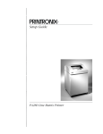
The printer generates characters by assembling groups of dots in matrices. Dots overlap to produce a
solid appearing character of uniform density as shown in Figure 1–1. Dot impressions are made by an
assembly of hammers installed on an oscillating shuttle. P3000 Series printers have 34 hammers. The
hammers impact the paper through a moving ink ribbon. Horizontal shuttle movement and vertical
paper advancement combine for precise dot printing to form the character matrix.
Figure 1–1. Typical Character Formation
Overview
1–3
Line Matrix Printing
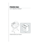
Unlike moving–head dot matrix printers, Printronix P3000 Series printers create graphics and characters by printing an entire dot row at one time. As shown in Figure 1–2, dots are printed in both directions of shuttle travel at a printer stroke length of .4 inches to print through several character positions
in 10 pitch Data Processing print mode. By printing a row of dots, line matrix printers achieve higher
print duty cycles than moving head dot matrix (serial) printers.
During each sweep of the shuttle, hammers are activated to print dots at selected positions in that dot
row. When the shuttle reaches the end of a sweep, it reverses direction, paper advances one dot row, and
the hammers print the next consecutive row of dots.
After an entire line of characters is printed, hammer print action ceases and the paper advances to the
first dot row of the next print line. This creates a series of blank rows between lines of characters. The
number of rows allowed for line separation depends on the line spacing selected. Line spacing may be
selected from the control panel or the host computer.
DIRECTION OF SHUTTLE MOVEMENT
DOT
ROW
ONE
CHARACTER
ROW
1
2
3
4
5
6
7
8
9
10
11
12
1
2
PAPER
ADVANCES
START
PAPER
FEED
*
* *
PAPER
ADVANCES
SPACE
1 HAMMER
PRINT SPAN
* USED FOR LOWERCASE DESCENDER ONLY
** USED FOR UNDERLINE AND LOWERCASE DESCENDER
NOTE: P3000 shuttle sweeps through 4 character spaces at 10 cpi.
Figure 1–2. Line Matrix Printing
Print Rate
The print rate, in lines per minute (lpm), is a function of the number of dot rows required to produce the
character line regardless of the number of characters in the line. For example, more dot rows are required to print lowercase characters with descenders; consequently, those characters are printed at a
slower rate. Table 1–1 describes the print rate according to type of character printed and print mode.
Complete printing specifications are provided in Appendix C.
1–4
Overview
Table 1–1. P3000 Series Print Rates
Uppercase Only
Print Mode
Upper/Lowercase
Data Processing (DP)
300
240
Correspondence (NLQ)
175
134
High Speed (HS)
400
350
Barcode 145
267
214
Barcode 160
250
200
Plot Rate
As well as character printing, the P3000 Series printers are capable of dot–addressable graphic plotting. Based on the protocol selected, either P–Series Plot Mode or Serial Matrix Bit Image Graphics is
used; the plot rate specifications apply to both P–Series and Serial Matrix types of graphic plotting.
The bidirectional plot rate (in inches per minute, “ipm”) is described in Table 1–2 according to the dot
density (in dots per inch, “dpi”). Complete plotting specifications are provided in Appendix C.
Table 1–2. Plot Rates
Density (dpi)
P3000 Plot Rates
(ipm)
60 Horiz x 72 Vert (DP mode)
33
90 Horiz x 96 Vert (NLQ mode)
18
60 Horiz x 48 Vert (HS mode)
50
72.5 Horiz x 72 Vert (Barcode 145 mode)
15
80 Horiz x 72 Vert (Barcode 160 mode)
14
NOTE: Unidirectional plotting produces better print quality than bidirectional, and can be
selected from the control panel; however, unidirectional plot reduces the plot rate to half.
Overview
1–5
1–6
Overview
CHAPTER 2
OPERATION
Introduction
This chapter describes P3000 Series controls and operating procedures. The following information is
discussed in this chapter:
Operation
•
Basic Operation Features . . . . . . . . . . . . . . . . . . . . . . . . . . . . . Page 2–2
•
Power Switch . . . . . . . . . . . . . . . . . . . . . . . . . . . . . . . . . . . . . . Page 2–3
•
Control Panel Switches and Indicators . . . . . . . . . . . . . . . . . . Page 2–4
•
Loading Paper . . . . . . . . . . . . . . . . . . . . . . . . . . . . . . . . . . . . . Page 2–9
•
Unloading Paper . . . . . . . . . . . . . . . . . . . . . . . . . . . . . . . . . . . Page 2–11
•
Replacing the Ribbon . . . . . . . . . . . . . . . . . . . . . . . . . . . . . . . Page 2–11
•
Setting Top–of–Form . . . . . . . . . . . . . . . . . . . . . . . . . . . . . . . Page 2–12
•
Paper Stacking (Floor Cabinet Models) . . . . . . . . . . . . . . . . . Page 2–14
•
Setting Forms Length . . . . . . . . . . . . . . . . . . . . . . . . . . . . . . . Page 2–15
•
Selecting Print Mode . . . . . . . . . . . . . . . . . . . . . . . . . . . . . . . Page 2–16
•
Setting Line Spacing . . . . . . . . . . . . . . . . . . . . . . . . . . . . . . . Page 2–17
•
Printer Reset . . . . . . . . . . . . . . . . . . . . . . . . . . . . . . . . . . . . . . Page 2–17
2–1
Basic Operation Features
On Line
The printer functions either “on line” or “off line.” When on line, the printer is capable of receiving
data and control commands from the host computer. The message display on the printer control panel
indicates that the printer is on line and shows the current print mode.
Off Line
When the printer is off line, communication between the printer and the host computer is temporarily
stopped and the message OFFLINE READY appears on the display. Set the printer off line to perform
the following tasks:
•
Display/Change Configuration Values
•
Load Paper and Ribbon
•
Run the Self–Test
•
Advance to Top of Form
•
Set Top–of–Form
•
Change Print Modes
•
Enter Hex Dump Mode
•
Adjust Paper Tractors
•
Set Line Spacing
•
Advance Paper
Command Sets (Protocol Modes)
The P3000 Series Multinational printers respond to two different command sets (protocols): P–Series
and Serial Matrix.
The protocol is selected from the control panel and must correspond with the programming standard
used by the host computer to communicate with the printer. You can select either protocol as required
by the application. The P–Series emulation mode generates characters and graphics using Printronix
standard P–Series control code protocol. The Serial Matrix emulation mode generates characters and
graphics using Serial Matrix control code protocol similar to the IBM Graphics Printer. Refer to the
Programming chapter for detailed information on P–Series and Serial Matrix protocols and control
code definitions.
Character Set Options
Four basic character set choices are selectable from the control panel: IBM PC, Multinational,
ECMA–94 Latin 1, and DEC Multinational. Within each character set, specify the desired specific foreign language set.
You can also define and download a custom character substitution table to replace any symbol residing
in the character library (see page 6–31). This downloading feature is discussed in more detail in the
Programming chapter.
2–2
Operation
Power Switch
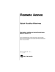
On pedestal model printers (P3040 and P3040–12), the AC power switch is located on the rear panel of
the printer. The floor cabinet model (P3240) power switch is located at the lower left corner of the rear
panel. (Refer to Figure 2–1.) To turn the printer power on, set the power switch to the ON (|) position.
Power Switch – Pedestal Models
Power Switch – Floor Cabinet Model
Figure 2–1. Power Switch
Operation
2–3
Control Panel Switches and Indicators
The printer control panels contain twelve momentary–contact switches (16 switches if the printer has
the PI–3287 option), four Light–Emitting Diode (LED) indicators (eight if the printer has the PI–3287
option), and a 32–character alphanumeric Message Display, as shown in Figure 2–2. The eight configuration function switches on the Display control panel are accessible only when the printer cover is
raised. These switches and indicators are described on the following pages.
Exterior Control Panel:
ON LINE
CHECK
8 LPI
VFU
ON LINE
CLEAR
6/8 LPI
PAPER
ADV
Accessible with the Printer Cover Open:
ALPHANUMERIC
MESSAGE DISPLAY
UP
NEXT
MENU
VALUE
DOWN
PREV
F/L
R/S
MODE
ENTER
Exterior Control Panel with the PI–3287 Option:
ON LINE
CHECK
8 LPI
VFU
HOLD
READY
ERROR
ALT
ENABLE/
HOLD
CLEAR
6/8 LPI
PA1
PA2
REPRINT
CANCEL
PAPER
ADV
ALT MODE
Figure 2–2. Control Panel
Alphanumeric Message Display
The Message Display shows printer status, operator selections, and fault condition messages. The display has two rows with sixteen characters per row. During normal operation, the display indicates the
on line status and the current print mode (and pitch) selection. When off line, the display reads OFFLINE READY or OFFLINE DATA IN BUFFER.
2–4
Operation
ON LINE Switch
Press this switch to place the printer alternately on line or off line. When the printer is on line, the ON
LINE LED lights. The printer must be on line to receive data from the host computer. When the printer
is on line, the display indicates the current print mode, and only the PAPER ADV control panel switch
functions. When the printer is off line, the display reads OFFLINE READY. All switches are active
(except the ENTER switch unless it has been unlocked), and the printer cannot communicate with the
host computer. The printer must be off line to change printing format or configuration and goes off line
automatically if a fault occurs.
If the display shows OFFLINE HEX DUMP (a diagnostic selection), pressing the ON LINE switch
causes the printer to go on line, and data from the host computer is printed in “hex dump” format. The
display shows ON LINE HEX DUMP. Pressing the ON LINE switch again takes the printer back to the
OFFLINE HEX DUMP state.
CLEAR Switch and CHECK Indicator
If a fault condition occurs, a fault message appears on the Message Display, and the CHECK indicator
flashes alternately with the ON LINE indicator. After you correct the fault condition, press the CLEAR
switch. The fault status will be validated and the display updated. If all faults were corrected, the display will indicate the printer is off line.
In addition, the CLEAR switch has the special functions noted below. Except when used to reset the
printer (#1 below), the CLEAR switch operates only when the printer is off line.
1.
Simultaneously pressing CLEAR and R/S (RUN/STOP) resets the printer. You may reset the
printer at any time, on line, off line, or while printing. However, it is recommended that you reset
the printer only when it is off line and no data is in the buffer, or loss of data may result.
2.
CLEAR is used with the PAPER ADV switch to set top–of–form. (Refer to Setting the Top–of–
Form section on page 2–12.)
3.
Pressing CLEAR when one of the configuration parameter values is displayed places the printer
back to off line status. Refer to the Control Panel Configuration Diagram in the Configuration
chapter.
4.
Pressing CLEAR silences the audio alarm during a fault condition.
6/8 LPI Switch
Press this switch to display the current line spacing in lines per inch (lpi). Subsequently pressing this
switch steps the selection through 6, 8 and 10.3 (7/72”) lpi. Use of the ENTER switch is not required to
select the line spacing. The LED next to this switch lights when line spacing is other than 6 lpi. The 6/8
LPI switch functions only when the printer is off line.
NOTE: Line spacing control from the host computer overrides the switch setting. Control
codes from the host computer can select line spacing other than the 6, 8, or 10.3 lpi and is
reflected on the message display.
Operation
2–5
PAPER ADV Switch
Momentarily press this switch to advance the paper one line, or press and hold the switch to advance to
the top–of–form of the next page. This switch can be configured to advance the paper only after printing any data remaining in the buffer, or to move paper without printing. (Refer to the Configuration
chapter.) When the printer is on line, press the PAPER ADV switch to advance to the next top–of–
form. However, if there is any data in the buffer, no paper motion occurs and the message ON LINE
DATA IN BUFFER momentarily displays.
NOTE: If the Paper Advance Switch is configured for Move Paper Only and data from the
host does not end in a paper motion command, the last line of text will print on the first line
of the next page.
The PAPER ADV switch is also used to set top–of–form. (Refer to Setting Top–of–Form section on
page 2–12.)
VFU LOADED Indicator
This LED indicator lights when the form (paper) format is being controlled by the Vertical Format
Unit. (Refer to the Configuration and VFU chapters.) When the appropriate VFU is selected by the
operator and loaded by the host computer, this indicator lights.
ENABLE/HOLD, PA1 REPRINT, PA2 CANCEL, ALT MODE
(Optional Switches)
These four switches and their associated LEDs are included on printers equipped with a Printronix
PI–3287 printer interface and operate independently of all other control panel switches. The PI–3287
enables a Printronix printer to emulate an IBM 3287 printer; the printer may then be used with an IBM
3274 or 3276 control unit. Information on the operation and function of these switches is contained in
the PI–3287 User’s Reference Manual. If the printer is not configured to emulate an IBM 3287 printer,
these switches are not provided.
THE SWITCHES DESCRIBED BELOW ARE ACCESSED BY
RAISING THE PRINTER COVER:
MENU UP, MENU DOWN, NEXT, and PREV Switches
To make configuration changes, the ENTER switch must be unlocked. When the printer is OFFLINE
READY, simultaneously pressing MENU UP and MENU DOWN alternately locks and unlocks the
ENTER switch. No other switches are affected by this action. Use the MENU UP, MENU DOWN,
NEXT, and PREV switches to display configuration parameter main menus, submenus, and certain
diagnostic tests. After the required menu displays, use the NEXT and PREV switches (shown on the
Control Panel Configuration Diagram in the Configuration chapter) to display individual parameters.
The value shown on the display with an asterisk (*) is the current parameter value retained in printer
memory.
2–6
Operation
NOTE: When the printer is off line, configuration menus and parameter values may be
viewed at any time. To make any configuration changes, you must first unlock the ENTER
switch from the OFFLINE READY display. The ENTER switch cannot be unlocked or
locked from within a menu. Pressing ENTER loads a displayed configuration value into
printer working memory. However, these configuration changes will be lost when the printer is powered down unless saved. Be sure to relock the configuration after you have made
your changes.
R/S Switch
R/S (Run/Stop) performs the following functions:
•
Press R/S simultaneously with CLEAR to reset the printer.
•
If a diagnostic test is selected and shown on the display, press R/S to start the test and press it
again to stop the test.
•
If the CONFIGURATION PRINTOUT message is selected and shown on the display, press
R/S to print a list of the current configuration.
ENTER Switch
Press ENTER to enter a displayed parameter value into printer working memory. The previous value is
replaced by the displayed value. The ENTER switch must be used to alter a menu selection and those
parameters displayed using the MODE and F/L switches. (Functions activated by the R/S and 6/8 LPI
switches do not use the ENTER switch.)
The ENTER switch must be enabled (unlocked) before making configuration or format changes. Simultaneously pressing MENU UP and MENU DOWN alternately locks and unlocks the ENTER
switch. (This sequence protects against accidental reconfiguration.) No other switches are affected by
this action. The ENTER switch can only be locked or unlocked when the display shows OFFLINE
(and there is no data in the buffer), after which the display reads either ENTER SWITCH NOT
LOCKED or ENTER SWITCH LOCKED for approximately one second. The display then returns to
OFFLINE. Resetting the printer or turning the power off and on will relock the ENTER switch.
MODE Switch
The print MODE switch functions only when the printer is off line. Press this switch to display the
current print mode. Subsequently pressing the NEXT VALUE, PREV VALUE, or MODE switches
updates the Message Display through all of the available print modes listed below. Print mode is selected with the ENTER switch.
Operation
•
High Speed (HS) at 10, 12, 13.3, 15, and 17.1 cpi
•
Data Processing (DP) at 10, 12, 13.3, 15, and 17.1 cpi
•
Correspondence (NLQ) at 10, 12, and 15 cpi
•
OCR–A at 10 cpi
•
OCR–B at 10 cpi
2–7
•
Barcode 145 at 12.1 cpi
•
Barcode 160 at 13.3 cpi
NOTE: Print mode control from the host computer overrides the control panel setting.
F/L Switch
The F/L (Forms Length switch functions only with the printer off line. Press F/L to enter the Forms
Length menus.
You can select Forms Length in inches or lines via printer configuration. Refer to the Setting Forms
Length section on page 2–15.
You can also set Forms Length by control code from the host computer. Forms length control from the
host computer overrides the control panel setting. Refer to the Programming chapter for details.
2–8
Operation
Loading Paper
The printer uses standard fanfold paper from 3 to 16 inches wide (perforation to perforation) and 15 to
100 lb. bond (0.025 inches thick maximum). To load paper, perform the following steps and refer to
Figure 2–3.
1.
Place the printer off line and raise the printer cover.
2.
Fully raise the Forms Thickness Adjustment Lever (A).
3.
Open both tractor gates (B) by swinging them out.
4.
Feed the paper up through the paper slot at the base of the printer. (In floor cabinet models, open
the front printer door and align the paper supply with the position of the tractor sprockets (D).
Feed the paper up through the paper slot until it appears above the ribbon mask (C). If the paper
snags, fold the top edge down before feeding.
5.
Load the paper on the tractor sprockets (D); close the tractor gates (B). If necessary, slide the right
tractor to remove paper slack or to adjust for various paper widths by releasing the right tractor
lock (E) by raising or lowering it to the center; slide the tractor into position. After positioning the
tractor, lock it in place.
NOTE: Lock the left tractor in alignment with the number “1” on the paper scale to set the
left margin with the first character space.
6.
Continue to feed the paper through the paper path at the top of the cabinet (F).
7.
For printers with a Quick Access cover, close the printer cover. Open the plastic Quick Access
cover by pulling the Quick Access lever located on the right side of the printer. Feed the paper
through the clear plastic Quick Access cover.
8.
Press PAPER ADV to advance paper into the paper stacking area. Verify unobstructed paper
feeding.
9.
Set the Forms Thickness Adjustment Lever (A) with slight friction to approximate the paper
thickness. The A–B–C scale indicates relative positioning to correspond approximately with 1–
to 6–part paper thicknesses. (If closed too tightly, the shuttle may stall or tear the paper.)
10. Set the top–of–form as described in the Setting Top–of–Form procedure on page 2–12.
11. Close the printer cover.
12. Press CLEAR and place the printer on line.
NOTE: The P3040 is the pedestal model illustrated throughout this manual.
Operation
2–9
Figure 2–3. Loading Paper
2–10
Operation
Unloading Paper
1.
Place the printer off line.
2.
Tear off the paper at the slot at the bottom of the printer.
3.
Fully raise the Forms Thickness Adjustment Lever.
4.
Open both tractor gates and remove the paper from the tractor sprockets.
5.
Gently pull the paper up through the paper slot. Be careful not to let paper perforations or sprocket holes catch on the ribbon mask.
Replacing the Ribbon
Each printer is shipped with a standard black ink, one–inch nylon fabric ribbon on two spools. OCR
(extra dark) ribbons are also available. Replace the ribbon when the print contrast is too light or approximately after each box of standard size computer paper. To replace the ribbon, perform the following steps and refer to Figure 2–4.
1.
Place the printer off line and raise the top cover.
2.
Fully raise the Forms Thickness Adjustment Lever (A) to open the platen. (To disable the audio
alarm, press the CLEAR switch.)
3.
Unlatch the ribbon spools (B) and carefully lift them off the hubs (C). Raise the ribbon out of the
ribbon path. Discard the used ribbon.
4.
Place each new ribbon spool (B) on a hub (C) with the ribbon to the outside. Either ribbon spool
can be loaded on either hub.
5.
Press the spools down until the latch (D) snaps in place.
6.
Thread the ribbon around the two ribbon guides (E) and through the ribbon path as shown in the
diagram (F) on the ribbon deck cover. The ribbon must pass between the two thin metallic strips
called the hammer bank cover (G) and the ribbon mask (H). Manually turn the ribbon spools to
ensure that the ribbon is tracking correctly in the ribbon path.
CAUTION
The ribbon must not be twisted. A twisted ribbon can lower print quality, shorten ribbon life, or cause paper jams.
VORSICHT
Das Farbband darf nicht verdreht sein. Ein verdrehtes Farbband kann die
Druckqualität und die Farbbandlebensdauer erniedrigen, oder könnte
Papiertransportfehler hervorrufen.
7.
Operation
Lower the Forms Thickness Adjustment Lever (A) to the appropriate operating position.
2–11
Figure 2–4. Ribbon Replacement
8.
Press CLEAR (on the control panel) to clear the PLATEN OPEN fault condition.
9.
Close the top cover and place the printer on line.
Setting Top–Of–Form
Top–of–form determines where the first line of print will appear and is set when paper is loaded. Typically, the first line of print is set approximately one–half inch below the paper perforation unless specific application requirements dictate otherwise.
Once top–of–form has been set, press and hold the PAPER ADV switch to advance to the top of the
next form. Unless otherwise configured, the printer assumes 11–inch length paper is used. For alternate length forms, refer to Setting Forms Length on page 2–15.
2–12
Operation
There are two methods of setting top–of–form. The first method uses forward paper motion and is performed with the Forms Thickness Adjustment Lever closed. The second method uses reverse paper
motion and is performed with the Forms Thickness Adjustment Lever open.
Use the reverse paper motion method when the forms length setting in the printer is different from the
actual forms length set (for example, when the host sets the forms length for non–standard length
forms). The reverse paper motion method of setting top–of–form reverse feeds the paper backward a
fixed number of inches and does not use the forms length currently set in the printer.
NOTE: Do not use the reverse paper motion method of setting top–of–form for heavy forms
or peel–off label forms.
Setting Top–of–Form – Forward Paper Motion
1.
Place the printer off line and raise the printer cover.
2.
Move the Forms Thickness Adjustment Lever to the fully open position. (The CHECK indicator
lights, the status lamps flash alternately, and FAULT CONDITION PLATEN OPEN displays.)
3.
Rotate the Vertical Position Knob (on the right side of the printer) to align the first print line with
the top–of–form alignment notch on the left tractor gate (A, Figure 2–5).
4.
Close the Forms Thickness Adjustment Lever to the appropriate paper thickness position.
5.
Press and release the CLEAR and PAPER ADV switches simultaneously. The paper advances to
the top–of–form position on the next form. The display reads OFFLINE/TOP OF FORM SET.
6.
Close the printer cover and place the printer on line.
Figure 2–5. Setting Top–of–Form
Operation
2–13
Setting Top–of–Form – Reverse Paper Motion
NOTE: Do not use this method of setting top–of–form for heavy forms or peel–off label
forms.
1.
Place the printer off line and raise the printer cover.
2.
Move the Forms Thickness Adjustment Lever to the fully open position. (The CHECK indicator
lights, the status lamps flash alternately, and FAULT CONDITION PLATEN OPEN display.)
3.
Rotate the Vertical Position Knob (on the right side of the printer) to align the first print line with
the top–of–form alignment indicator on the left tractor gate (Figure 2–5).
NOTE: Be sure there is enough paper extending through the tractor area so that forms do
not run out of the tractors during the reverse feed in the following step.
4.
Press and release the CLEAR and PAPER ADV switches simultaneously. The paper reverses
feed to the top–of–form position on the current form.
5.
Close the Forms Thickness Adjustment Lever to the appropriate paper thickness position.
6.
Press the CLEAR switch to clear the PLATEN OPEN fault condition.
7.
Close the printer cover and place the printer on line.
Paper Stacking (Floor Cabinet Model)
NOTE: The following paper stacking instructions pertain to the floor cabinet model printer
only. For pedestal models, refer to the paper stacking instructions accompanying your paper basket/stacking kit.
The floor cabinet model printer can stack at least half a box of standard computer paper when the paper
is properly loaded. After loading the paper, perform the following steps.
2–14
1.
Open the rear cabinet door to access the paper stacking area.
2.
Advance the paper until a few sheets begin to stack on the floor of the printer cabinet.
3.
Verify the following and make any necessary adjustments.
a.
The paper perforation folds are folding naturally.
b.
The paper is following a straight path down to the paper stack.
4.
Run the printer and stack approximately 15 to 20 sheets of paper.
5.
Repeat step 3. Any adjustments to the paper stack can be made while the printer is running. If an
adjustment is made, check the stack again after approximately 15 to 20 sheets have been processed.
Operation
NOTE: If the paper is not stacking properly, check the following items in addition to those
listed in step 3:
1.
If printing occurs across the paper perforations, the paper may not stack correctly. Adjust the Skip–Over Perforation configuration parameter to eliminate printing across
the paper perforations.
2.
If the paper path is too close to either side panel, paper stacking may be disrupted. Adjust the paper path toward the center of the printer, away from the side panels.
Setting Forms Length
NOTE: Forms length can also be set by control code from the host computer which overrides the control panel setting. Using control codes, the host computer can specify forms
lengths other than those available from the control panel. Refer to the Programming chapter for more information.
The printer uses continuous, tractor–fed paper with the forms length set between 1.0 and 24.0 inches,
or between 1 and 192 lines at 6 or 8 lines per inch. Setting the forms length in lines at 6 or 8 lpi does not
change the line spacing.
The printer has been preset for 11–inch length paper. When using paper of a different length, the top–
of–form setting and the forms length setting must be changed to match the designated length. To set the
forms length:
1.
Place the printer off line.
2.
Simultaneously press MENU UP and MENU DOWN to unlock the printer configuration. ENTER SWITCH NOT LOCKED displays for a moment.
3.
Press F/L; the display shows FORMS LENGTH SET IN INCHES.
4.
Press NEXT VALUE or PREV VALUE to cycle through the following options: FORMS
LENGTH SET IN 6 LPI LINES, FORMS LENGTH SET IN 8 LPI LINES, and FORMS
LENGTH SET IN INCHES. Select an option and perform the corresponding instructions below.
To Set Forms Length in Inches
1.
Press NEXT VALUE or PREV VALUE until FORMS LENGTH SET IN INCHES is displayed.
2.
Press MENU DOWN or F/L to display the current forms length in inches.
3.
Press NEXT VALUE or F/L to increase the forms length by 0.5 inches, or press PREV VALUE to
decrease the forms length by 0.5 inches. When the appropriate value is displayed, save it as described below.
4.
Press ENTER to select the displayed forms length.
5.
Press CLEAR to return to OFFLINE READY.
Operation
2–15
6.
Simultaneously press MENU UP and MENU DOWN to lock the printer configuration.
7.
Set the top–of–form according to the instructions on page 2–12.
To Set Forms Length in Lines
1.
Press NEXT VALUE or PREV VALUE until FORMS LENGTH SET IN 6 LPI LINES or
FORMS LENGTH SET IN 8 LPI LINES displays.
2.
Press MENU DOWN to display the current forms length in lines.
3.
Press NEXT VALUE to increase the forms length by one line, or press PREV VALUE to decrease
the forms length by one line. When the appropriate value displays, save it as described below.
4.
Press ENTER to select the displayed forms length.
5.
Press CLEAR to return to OFFLINE READY.
6.
Simultaneously press MENU UP and MENU DOWN to lock the printer configuration.
7.
Set the top of form according to the instructions on page 2–12.
Selecting Print Mode
During normal operation, the message display indicates the printer is on line and what print mode is
currently selected; for example:
ON LINE
DP AT 10 CPI
1.
Place the printer off line and raise the printer cover.
2.
Simultaneously press MENU UP and MENU DOWN. ENTER SWITCH NOT LOCKED displays momentarily.
3.
Press MODE. The currently selected print mode displays.
4.
Press NEXT VALUE or PREV VALUE to cycle through the various print mode options. The
following print mode options are available:
•
Data Processing (DP) at 10, 12, 13.3, 15, and 17.1 cpi
•
Correspondence (NLQ) at 10, 12 and 15 cpi
•
High Speed (HS) at 10, 12, 13.3, 15 and 17.1 cpi
•
OCR–A at 10 cpi
•
OCR–B at 10 cpi
•
Barcode 145 (12 cpi)
•
Barcode 160 (13.3 cpi)
NOTE: The control panel actually displays 13 or 17 cpi when 13.3 or 17.1 cpi, respectively,
is selected.
2–16
Operation
5.
When the desired print mode is shown on the display, press the ENTER switch.
6.
Press CLEAR to return the printer to off line status. The display reads OFFLINE READY.
7.
Simultaneously press MENU UP and MENU DOWN to lock the printer configuration.
8.
Close the printer cover and place the printer on line.
For additional printing capabilities and character attributes, refer to the Programming chapter. Print
mode control from the host overrides the control panel setting.
Setting Line Spacing
P3040 Multinational printers can be set for a line spacing of 6, 8, or 10.3 lines per inch (lpi) from the
control panel by using the 6/8 LPI switch. To select the line spacing from the control panel, perform the
following steps.
1.
Place the printer off line and raise the printer cover.
2.
Press 6/8 LPI. The currently selected lpi setting displays.
3.
Press NEXT, PREV, or 6/8 LPI to step through the 6, 8, and 10.3 lines–per–inch selections. The
light beside the 6/8 LPI switch lights when the selected line spacing is other than 6 lpi.
4.
Press CLEAR when the desired line spacing setting is displayed. The printer is placed off line and
the display reads OFFLINE READY.
5.
Close the printer cover and place the printer on line.
Line spacing can also be selected by sending line spacing control codes from the host computer as described in the Programming chapter. Using control codes, the host computer can specify line spacing
other than 6, 8, or 10.3 lpi. Line spacing control from the host computer overrides the control panel
setting.
Printer Reset
This function resets the printer to the configuration values last saved (not factory default values), and
the current form position becomes the top–of–form. The printer can be reset to the power–up configuration values at any time: on line, off line, or while printing. However, it is recommended that you reset
the printer only when it is off line to prevent the possible loss of data. The printer can also be reset
through the host. (Refer to the Programming chapter.)
To reset the printer, press CLEAR and RUN/STOP (R/S) simultaneously.
IMPORTANT
Information regarding Hex Code Printout, Running the Self–Test, and Fault
Condition Messages is located in the Routine Service and Diagnostics chapter.
Operation
2–17
2–18
Operation
CHAPTER 3
CONFIGURATION
Introduction
Configuration refers to the set of operating parameters that define how the printer responds to the electronic interface signals and the commands sent from the host computer. Most configuration parameters
are selected from the control panel, as shown in the Control Panel Configuration Diagram at the end of
this chapter.
Read this chapter before configuring any printer function. The following information is presented:
•
Lock/Unlock Printer Configuration . . . . . . . . . . . . . . . . . . . . . Page 3–1
•
Configuration Menus . . . . . . . . . . . . . . . . . . . . . . . . . . . . . . . . Page 3–1
•
Configuration Printout . . . . . . . . . . . . . . . . . . . . . . . . . . . . . . . Page 3–2
•
Factory Default Configuration Values . . . . . . . . . . . . . . . . . . . Page 3–4
•
Configuration Procedure . . . . . . . . . . . . . . . . . . . . . . . . . . . . . Page 3–5
•
Load Configuration Values . . . . . . . . . . . . . . . . . . . . . . . . . . . Page 3–6
•
Control Panel Configuration Diagram . . . . . . . . . . . . . . . . . . . Page 3–7
For more information on operating and configuring the Multinational Character Sets, refer to the Multinational Character Sets chapter.
Lock/Unlock Printer Configuration
The ENTER switch must be unlocked to reconfigure the printer from the control panel. At powerup,
the printer configuration is locked to prevent accidental reconfiguration. In order to change any configuration value, the ENTER switch must be unlocked. Pressing MENU UP and MENU DOWN simultaneously (while the printer is off line) will alternately unlock and lock the ENTER switch. The
message display will briefly read ENTER SWITCH NOT LOCKED or ENTER SWITCH LOCKED
when the printer configuration is unlocked or locked, respectively. While in the configuration menus,
pressing the ENTER switch will enter a selected value into printer configuration.
Configuration Menus
With the printer off line, pressing MENU DOWN, then repeatedly pressing NEXT or PREV VALUE
displays the main configuration menus. The individual parameter values or secondary menus are displayed by again pressing MENU DOWN. All parameter options within a menu may be viewed by
pressing NEXT or PREV VALUE. Pressing MENU UP moves the configuration menu up one level.
Configuration
3–1
From the main configuration menus below, related configuration parameter values can be displayed
and selected.
•
Character Set
•
Application Compatibility
•
Paper Format
•
Host Interface
•
Load Parameters
•
Save Parameters
•
Diagnostics
Once the ENTER switch is unlocked, displayed values can be selected as the current configuration by
displaying the value in the message display and pressing ENTER. You can exit from a configuration
menu by pressing CLEAR, which places the printer off line.
NOTE: If an “E” is displayed in the upper right corner of the LCD, the VFU is enabled. If a
“L” is displayed in the lower right corner of the LCD, the VFU is loaded.
Configuration Printout
The configuration printout lists all of the currently selected configuration parameter values. A sample
configuration printout is shown in Figure 3–1. Configuration parameters on the printout are listed in
the same order as the configuration menu via control panel.
The following general procedure is used to obtain a configuration printout. Refer to the Control Panel
Configuration Diagram beginning on page 3–7 for an illustration of the available menus and values.
When you return to OFFLINE READY, the previous print mode and LPI is restored, and all print attributes are canceled. All other format parameters are unaffected.
3–2
1.
Place the printer off line.
2.
Select and display the CONFIGURATION PRINTOUT menu in the DIAGNOSTICS menu by
pressing MENU DOWN and then PREV VALUE until DIAGNOSTICS appears in the message
area.
3.
Press MENU DOWN to display CONFIGURATION PRINTOUT in the message area.
4.
Press R/S. The configuration printout prints.
5.
Press CLEAR to return to OFFLINE READY.
6.
Place the printer on line.
Configuration
Figure 3–1. Sample Configuration Printout
Configuration
3–3
Factory Default Configuration Values
The printer comes with a set of Printronix factory configuration values, shown in Table 3–1. These
values are set at the factory, and are operational when the printer is received. New values can be saved
and applied as necessary for each application, but factory default values remain accessible using the
LOAD PARAMETERS configuration. On the Control Panel Configuration Diagram, factory configuration values are indicated by a asterisk (*). (The asterisk is not shown on the printer display.) Refer to
the Configuration Procedure on page 3–5 to change values of the configuration parameters for your
application.
Table 3–1. Printronix Factory Default Configuration Values
Configuration
Parameter
3–4
Factory Default
Value
Configuration
Parameter
Forms Length
Line Spacing
Print Mode
Select Set
Select Language
Select Subset
11.0 Inches
6 lpi
DP 10 cpi
IBM PC
ASCII
IBM PC Graphics
Parallel Interfaces:
Printer Protocol
P–Series
Serial RS–232 Interface:
Printer Select
Paper Advance Switch
Disable
PRINT + PAP ADV
Power On State
Alarm On Fault
Online
Enable
Unidirectional
Select SFCC
80–9F Hex
Control Code 08
Control Code 06
Overstrike
Disable
01 SOH
Control Codes
Double High
8 lpi
Enable
Auto Line Feed
Define CR Code
Define LF Code
VFU Select
Perforation Skip
Paper Empty
PMD Fault
Print Width
Host Interface
After Full Line
CR = CR
LF = CR + LF
EVFU
00.0 Inch
End of Paper
Enable
13.2 Inches
Centronics
Data Bit 8
Data Polarity
Resp. Polarity
PI Line
Strobe Polarity
Latch Data On
Data Protocol
Data Rate
Word Length
Stop Bit
Parity
Bit 8 Function
CD AND CTS
DSR
Data Term Ready
Request to Send
Reverse Channel
Factory Default
Value
Enable
Standard
Standard
Disable
Standard
Leading Edge
X–On / X–Off
9600 Baud
8 Bits
One
None
Font Select
Disable
Disable
Online and BNF
Online and BNF
Online and BNF
Configuration
Configuration Procedure
Most configuration options are selected from the control panel. To change the configuration from the
control panel, the printer must be powered up, off line (OFFLINE READY), and the control panel ENTER switch enabled (unlocked). The current configuration may be examined—but not changed—by
leaving the ENTER switch locked.
The basic configuration procedure requires pressing MENU DOWN and NEXT or PREV VALUE to
arrive at the desired menu. The parameters associated with that menu are accessed by again pressing
MENU DOWN, at which time the currently active parameter or a submenu is displayed. NEXT or
PREV VALUE are used to sequentially list all the parameters or submenus available within that menu.
When the currently active value is shown on the display, it will be indicated with an asterisk (*) next to
it. Pressing ENTER selects the parameter visible on the display, and replaces the previous parameter.
The Control Panel Configuration Diagram, which illustrates all configuration menus and values, is
provided at the end of this chapter. Thoroughly review these diagrams to understand the configuration
menu hierarchy and the control panel buttons to select individual menus and parameter values.
The following general procedure can be used to reconfigure the printer from the control panel:
1.
Obtain a current configuration printout as described in the Configuration Printout section on
page 3–2.
2.
Determine the parameter values that must be changed to meet your requirements. Refer to the
Control Panel Configuration Diagram for an illustration of the parameter values and the procedure required to select and display the values.
3.
Place the printer off line. Enable the ENTER switch by pressing MENU UP and MENU DOWN
simultaneously until the messages reads ENTER SWITCH NOT LOCKED.
4.
Select and display the desired menu by pressing MENU DOWN and then NEXT VALUE or
PREV VALUE until the name of the menu appears in the message display.
5.
Select and display the required value(s) for the selected menu item by pressing MENU DOWN
and then NEXT or PREV VALUE until the value appears in the message display.
6.
Save the selected value(s) by pressing ENTER.
7.
After all parameters have been changed as required, select the SAVE PARAMETERS main
menu and press ENTER. This will save the current parameter values as the default values.
8.
Press CLEAR to place printer off line. Disable the ENTER switch by pressing MENU UP and
MENU DOWN simultaneously. ENTER SWITCH LOCKED temporarily appears in the message display.
9.
Place the printer on line by pressing ON LINE. The selected values are effective.
Configuration
3–5
Load Configuration Values
The previously saved default value set or the permanently stored Printronix factory value set can be
loaded for use as needed. This procedure provides a convenient method of resetting the printer configuration to a known value set.
3–6
1.
Place the printer off line by pressing ON LINE. Enable the ENTER switch by pressing MENU
UP and MENU DOWN simultaneously. ENTER SWITCH NOT LOCKED temporarily appears
in the message area.
2.
Select and display the LOAD PARAMETERS main menu by pressing MENU DOWN and then
NEXT or PREV VALUE.
3.
Press MENU DOWN and then NEXT or PREV VALUE to select either the LOAD SAVED PARAMETERS or LOAD FACTORY PARAMETERS menu. If an IGP, IBM 3287, or IBM 5225
emulation board is installed, select the appropriate standard configuration listed in this menu.
4.
Press ENTER once the desired selection is shown in the message display. The display then reads
LOAD SAVED COMPLETED or LOAD FACTORY COMPLETED.
5.
After all parameters have been changed as required, select the SAVE PARAMETERS main
menu and press ENTER. This saves the current parameter values as the default values.
6.
Press CLEAR to return to OFFLINE READY.
7.
Disable the ENTER switch by pressing MENU UP and MENU DOWN simultaneously. Place
the printer on line by pressing ON LINE.
Configuration
Control Panel Configuration Diagram
The Control Panel Configuration Diagram is a series of block diagrams that show the configuration
menus and the parameters (values) available within each menu. Boxes on the diagram represent the
message area, the message that appears on the display is printed inside the box, and the letters outside
the boxes adjacent to the directional arrows represent control panel switches. When a switch is
pressed, an arrow leads to the displayed result of pressing that switch. The symbols used on the Control
Panel Configuration Diagram are summarized in Figure 3–2.
The diagram is presented in 3 levels, each level illustrating a particular set of parameter menus and
values. The relationships between the three levels are summarized in Figure 3–3.
Level I – Print Format
⋅
Line Spacing
⋅
Print Mode
⋅
Forms Length Set
Level II – Main Configuration Menus
⋅
Character Set
⋅
Application Compatibility
⋅
Paper Format
⋅
Host Interface
⋅
Load Parameters
⋅
Save Parameters
⋅
Diagnostics
Level III – Configuration Menu Parameters
Configuration
Select Set IBM PC
Select Set Multinational
Select Set ECMA–94 Latin 1
Select Set DEC Multinational
Printer Protocol
Printer Select
Paper Advance Switch
Power On State
Alarm On Fault
Unidirectional
Select SFCC
80–9F Hex
Control Code 06
Control Code 08
Overstrike
3–7
Level III – Configuration Menu Parameters (continued)
Auto Line Feed
Define CR Code
Define LF Code
VFU Select
VFU Table (Save/Clear)
Perforation Skip
Paper Out
PMD Fault
Print Width
Centronics Interface Parameters
Dataproducts Interface Parameters
Serial RS–232 Interface Parameters
Data Bit 8
PI Line
Data PolarityCD and CTS
Response Polarity
Strobe Polarity
Latch Data On
Data Protocol
Data Rate
Word Length
Stop Bit
Parity
Bit 8 Function
Load Saved Parameters
Load IGP Parameters
Load IBM 3287 Parameters
Load IBM 5225 Parameters
Load Factory Parameters
Configuration Printout
Print Data Stream In Hex Code
Printer Test 8 Inch Width
Printer Test Full Width
Shift Recycle
Ribbon
All E’s
E Plus TOF
All H’s
Underline Only
Black Plot
DSR
Data Term Ready
Request To Send
Reverse Channel
Shuttle/
Stroke Time
Shuttle Rebound Index
Hammer Phasing Index
3–8
Configuration
CONTROL PANEL
CONFIGURATION
DIAGRAM SYMBOLS:
MESSAGE
DISPLAY
OL = PRESS
ON LINE
CL = PRESS
CLEAR
LS = PRESS
6/8
LPI
PA = PRESS
PAPER
ADV
D = PRESS
MENU
DOWN
U = PRESS
MENU
UP
N = PRESS
NEXT
VALUE
P = PRESS
PREV
VALUE
RS = PRESS
R/S
E = PRESS
ENTER
PM = PRESS
MODE
FL = PRESS
F/L
+ = PRESS SWITCHES SIMULTANEOUSLY
* = FACTORY DEFAULT SETTING
= ARROWS LEAD TO THE
RESULT AFTER PRESSING THE
INDICATED SWITCH
Figure 3–2. P3000 Control Panel Configuration Diagram Symbols
Configuration
3–9
ON LINE
DP AT 10 CPI
*
NOTE: DP 10 CPI is the factory
print mode setting.
OL
Pressing MENU UP and MENU
DOWN
simultaneously will alternately lock/
unlock the ENTER switch. ENTER
SWITCH NOT LOCKED or ENTER
SWITCH LOCKED appears on the
display for one second.
OL
U+D
OFFLINE
READY
Press OL in any submenu (except when
running diagnostic tests) to place the printer
ON LINE.
D
LS, PM, FL
LEVEL I
LEVEL II
U or CL
U or CL
Print Format
(Sheet 1)
Main
Configuration
Menus
(Sheet 2)
D
NOTE: MODE, LINE SPACING or FORMS
LENGTH menus may be accessed from
any other menu except when running
diagnostic tests.
NOTE: Pressing R/S and CLEAR
simultaneously
resets the printer to default values.
U
LEVEL III
CL
Configuration
Menu
Parameters
(Sheets 3–15)
Figure 3–3. Control Panel Overview
3–10
Configuration
Configuration
LEVEL I – PRINT FORMAT
ON LINE
DP AT 10 CPI
OL
LS
OFFLINE
READY
PM
LINE SPACING
SET AT 6 LPI
P
P
*
P
LS or N
LINE SPACING
SET AT 8 LPI
P
PRINT MODE
DP AT 10 CPI
CL
CL
FL
CL
P FORMS LENGTH SET
IN INCHES
CL
*
N or PM
(1)
P
DP AT 12 CPI
DP AT 13 CPI
DP AT 15 CPI
DP AT 17 CPI
FORMS LENGTH SET
AT 11.0 INCHES
LINE SPACING
SET AT 10.3 LPI
HS AT 10 CPI
HS AT 12 CPI
HS AT 13 CPI
HS AT 15 CPI
HS AT 17 CPI
LS or N
P
CL
N or PM
P
FORMS LENGTH SET
AT 66 LINES
P
U
N
D
U
*
N or FL
P
FORMS LENGTH SET
AT 10.5 INCHES
U
N or FL
N or PM
PRINT MODE
BARCODE 160
N
FORMS LENGTH
RANGE IS FROM
1 TO 192 LINES
CL
FORMS LENGTH SET
AT 88 LINES
P
U
N
N FORMS LENGTH SET
AT 65 LINES
P
U
N
FORMS LENGTH
RANGE IS FROM
1 TO 192 LINES
N
P
N FORMS LENGTH SET
AT 87 LINES
(1) The menu selections may vary
when optional font PROMs are
installed.
(2) If a VFU is enabled and loaded,
FORMS LENGTH SET BY VFU
Will be displayed.
3–11
Control Panel Configuration Diagram (sheet 1 of 15)
U
*
N
P
OCR–A AT 10 CPI
OCR–B AT 10 CPI
BARCODE 145
P
U
N or FL
FORMS LENGTH
RANGE IS FROM
1.0 TO 24.0
INCHES IN 0.5
INCH INCREMENTS
CL
FORMS LENGTH SET
IN 8 LPI LINES
P
D
*
NLQ AT 10 CPI
NLQ AT 12 CPI
NLQ AT 15 CPI
LS or N
N
D or FL
(2)
U
P
CL
FORMS LENGTH SET
IN 6 LPI LINES
P
U
U
3–12
LEVEL II – MAIN CONFIGURATION MENUS
ON LINE
DP AT 10 CPI
NOTE: If configuration changes are to be made,
unlock the ENTER switch at this point by
simultaneously pressing MENU UP and MENU DOWN.
OL
OFFLINE
READY
D
U or CL
P
N
SHEET 3
U
N
SHEET 4
U
N
SHEET 6
D
U
D
P
LOAD PARAMETERS
D
U
U or CL
P
HOST INTERFACE
N
D
C
U or CL
P
PAPER FORMAT
D
B
U or CL
P
APPLICATION
COMPATIBILITY
D
A
U or CL
P
CHARACTER SET
E
SHEET 8
N
U
SHEET 13
U or CL
N
D
U or CL
N
DIAGNOSTICS
SAVE PARAMETERS
P
P
E
(1)
U
F
SAVE PARAMETERS
COMPLETED
SHEET 14
(1) Returns after 1 second
Configuration
Control Panel Configuration Diagram (sheet 2 of 15)
Configuration
FROM SHEET 2
A
LEVEL III – CONFIGURATION MENU PARAMETERS
CHARACTER SET
D
P
U
U
P
SELECT SET
IBM PC
U
P
SELECT SET
MULTINATIONAL
*
N
(1)
D
(2)
D
N
D
U
D
P
N
*
N
(3) (4)
FRENCH
GERMAN
ENGLISH
DANISH
SWEDISH
ITALIAN
SPANISH
JAPANESE
FRENCH CANADIAN
P
N
U
*
P
P
(3) (4)
D
U
*
P
N
P
SELECT LANGUAGE
EBCDIC
P
N
D
U
SELECT LANGUAGE
MULTINATIONAL
(3) (4)
GERMAN
SWEDISH
DANISH
NORWEGIAN
FINNISH
ENGLISH
DUTCH
FRENCH
SPANISH
ITALIAN
TURKISH
SELECT LANGUAGE
LATIN AM
NOTE: OCR–A and OCR–B are
selected from the print format at
level 1 on the configuration diagram
(with DP, NLQ, and HS features).
SELECT SUBSET
EXTENDED
SELECT LANGUAGE
ASCII
N
N
(5)
U
SELECT SUBSET
PRIMARY
SELECT LANGUAGE
ASCII
SELECT LANGUAGE
ASCII
SELECT SET
DEC MULTINAT.
N
U
P
U
P
SELECT SET
ECMA–94 LATIN 1
N
P
P
*
*
P
(3)
MULTINAT. DP 10
MULTINAT. DP 12
U
U
SELECT LANGUAGE
ASCII
N
(3) (4)
FRENCH
GERMAN
U
U
ENGLISH
P
N
N
NORW./DAN.
SWEDISH
SELECT LANGUAGE
MULTINAT. NLQ 10
ITALIAN
SPANISH
JAPANESE
FRENCH CANADIAN
DUTCH
N
FINNISH
SELECT LANGUAGE
JAPANESE
P
N
(1)
EXTENDED SUBSET is IBM PC GRAPHICS
(2)
EXTENDED SUBSET is MULTINATIONAL
(3)
The menu selections may vary when optional font PROMS are installed
(4)
DOWNLOADED is displayed when a downloaded substitution table is active
(5)
EXTENDED SUBSET is DEC MULTINATIONAL
3–13
Control Panel Configuration Diagram (sheet 3 of 15)
N
SELECT LANGUAGE
SWISS
3–14
FROM SHEET 2
B
APPLICATION
COMPATIBILITY
D
Continued
on sheet 5
U
N
U
P
P
PRINTER
P
PROTOCOL
U
PRINTER SELECT
N
D
U
P
PAPER ADVANCE SW
P
UNIDIRECTIONAL
N
D
P
P
ALARM ON FAULT
N
D
U
P
POWER ON STATE
N
D
U
P
U
N
N
D
D
PRINTER PROTOCOL
P–SERIES
U
*
*
N or P
N or P
PRINTER PROTOCOL
SERIAL MATRIX
U
PRINTER SELECT
DISABLE
U
PAPER ADVANCE SW
PRINT + PAP ADV
U
*
*
U
PAPER ADVANCE SW
MOVE PAPER ONLY
ALARM ON FAULT
ENABLE
U
*
UNIDIRECTIONAL
DISABLE
U
*
N or P
N or P
PRINTER SELECT
ON=DC1 / OFF=DC3
U
POWER ON STATE
ON LINE
N or P
U
POWER ON STATE
OFFLINE
N or P
U
ALARM ON FAULT
DISABLE
U
(1)
(1) Not applicable in P–Series (menu box not displayed)
Configuration
Control Panel Configuration Diagram (sheet 4 of 15)
UNIDIRECTIONAL
P–SERIES PLOT
U
Configuration
Continued from
sheet 4
U
N
P
U
U
U
P
P
SELECT SFCC
80–9F HEX
N
U
P
CONTROL CODE 08
N
OVERSTRIKE
N
D
P
U
*
80–9F HEX
PRINTABLE
CONTROL CODE 08
DOUBLE HIGH
U
*
OVERSTRIKE
ENABLE
N or P
U
CONTROL CODE 08
BACKSPACE
D
U
*
N or P
U
OVERSTRIKE
DISABLE
CONTROL CODE 06
8 LPI
U
*
N or P
U
CONTROL CODE 06
10.3 LPI
U
N
SELECT SFCC
5E HAT
P
80–9F HEX
CONTROL CODES
D
N
SELECT SFCC
1B ESC
P
U
(1)
D
N or P
N
SELECT SFCC
03 ETX
N
U
*
P
N
(1)
D
SELECT SFCC
01 SOH
CONTROL CODE 06
N
N
(1)
P
U
P
P
U
N
SELECT SFCC
7E TILDE
U
(1) Only available in P–Series protocol
(NOT APPLICABLE displayed in Serial Matrix protocol)
3–15
Control Panel Configuration Diagram (sheet 5 of 15)
U
3–16
CM
C
PAPER FORMAT
FROM SHEET 2
Continued
on sheet 7
U
N
P
U
P
P
AUTO LINE FEED
U
DEFINE CR CODE
U
U
P
VFU TABLE
N
U
P
VFU SELECT
N
D
U
P
DEFINE LF CODE
N
D
U
P
(2)
D
D
N
(2)
U
U
N
D
(3)
AUTO LINE FEED
AFTER FULL LINE
N or P
*
DEFINE CR CODE
CR = CR
*
N or P
DEFINE LF CODE
LF = CR + LF
U
VFU SELECT
EVFU
*
*
P
P
N or P
VFU TABLE
CLEARED
VFU TABLE
CLEAR
E
N
N or P
(3)
AUTO LINE FEED
DISABLE
DEFINE CR CODE
CR = CR + LF
DEFINE LF CODE
LF = LF
VFU TABLE
SAVED
VFU TABLE
SAVE
VFU SELECT
DVFU
E
(1)
P
N
VFU SELECT
DISABLE
N
(1) Not available in P–Series protocol
(menu box not displayed)
(2) VFU selections are not available in Serial Matrix protocol
(3) Returns after 1 second
Configuration
Control Panel Configuration Diagram (sheet 6 of 15)
Configuration
Continued from
sheet 6
U
N
P
U
P
N
U
P
N
PERFORATION SKIP
1/2 INCH
P
U
PAPER OUT
END OF PAPER
*
P
*
D
U
PMD FAULT
ENABLE
D
*
PMD FAULT
DISABLE
U
*
N or P
N or P
PRINT WIDTH
13.6 INCHES
N
N or P
PRINT WIDTH
8.0 INCHES
N
PERFORATION SKIP
5/6 INCH
P
N
PRINT WIDTH
13.2 INCHES
PERFORATION SKIP
2/3 INCH
P
P
N
N or P
PAPER OUT
IMMEDIATE
U
PRINT WIDTH
N
D
PERFORATION SKIP
DISABLE
U
PMD FAULT
N
(1)
P
P
PAPER OUT
D
P
U
P
PERFORATION SKIP
(1)
If a DVFU is enabled and loaded, then DISABLE and ENABLE will be the only menu boxes displayed;
If the P–Series protocol EVFU is enabled and loaded, the DISABLED BY VFU will be displayed.
N
PERFORATION SKIP
1 INCH
N
3–17
Control Panel Configuration Diagram (sheet 7 of 15)
3–18
FROM SHEET 2
D
HOST INTERFACE
D
U
U
N
HOST INTERFACE
CENTRONICS
*
P
D
U
U
N
G
H
(1)
SHEET 9
FOR DATAPRODUCTS MENUS
P
(1)
P
U
N
D
N or P
DATA BIT 8
DISABLE
N
U
PI LINE
DISABLE
*
N or P
PI LINE
ENABLE
U
*
N or P
DATA POLARITY
INVERTED
LATCH DATA ON
STROBE POLARITY
N
N
D
D
RESP. POLARITY
STANDARD
*
N or P
RESP. POLARITY
INVERTED
N
D
U
U
DATA POLARITY
STANDARD
U
P
P
RESP. POLARITY
D
U
*
U
P
DATA POLARITY
N
DATA BIT 8
ENABLE
N
P
PI LINE
D
RS–232 MENUS
P
U
P
DATA BIT 8
SHEET 10
FOR SERIAL
U
STROBE POLARITY
STANDARD
*
N or P
STROBE POLARITY
INVERTED
(1) Centronics and Dataproducts parameters cannot be set independently
Configuration
Control Panel Configuration Diagram (sheet 8 of 15)
U
LATCH DATA ON
LEADING EDGE
N or P
LATCH DATA ON
TRAILING EDGE
*
Configuration
HOST INTERFACE
DATAPRODUCTS
G
FROM SHEET 8
D
U
P
U
U
P
DATA BIT 8
N
PI LINE
DISABLE
*
N or P
DATA BIT 8
DISABLE
*
N or P
PI LINE
ENABLE
*
N or P
DATA POLARITY
INVERTED
N
D
U
DATA POLARITY
STANDARD
LATCH DATA ON
N
D
U
P
STROBE POLARITY
N
D
D
P
RESP. POLARITY
N
U
DATA BIT 8
ENABLE
P
DATA POLARITY
PI LINE
D
U
P
U
RESP. POLARITY
STANDARD
*
N or P
RESP. POLARITY
INVERTED
N
D
U
STROBE POLARITY
STANDARD
*
N or P
STROBE POLARITY
INVERTED
3–19
Control Panel Configuration Diagram (sheet 9 of 15)
U
LATCH DATA ON
LEADING EDGE
*
N or P
LATCH DATA ON
TRAILING EDGE
3–20
HOST INTERFACE
SERIAL RS–232
H
FROM SHEET 8
D
U
N
P
U
P
U
P
DATA PROTOCOL
U
U
P
WORD LENGTH
8 BITS
*
N
P
N
P
PARITY
NONE
*
N or P
WORD LENGTH
7 BITS
DATA RATE
1200 BAUD
N
P
DATA RATE
2400 BAUD
N
P
DATA RATE
4800 BAUD
P
P
N
PARITY
EVEN
N
P
N
P
N
N
DATA RATE
9600 BAUD
N
PARITY
ODD
STOP BIT
TWO
DATA RATE
600 BAUD
DATA PROTOCOL
DTR, RC, OR RTS
*
P
N or P
N
DATA PROTOCOL
ETX / ACK
P
STOP BIT
ONE
DATA RATE
300 BAUD
DATA PROTOCOL
ACK / NAK
P
U
P
DATA RATE
150 BAUD
N
D
U
P
*
N
N
D
U
P
PARITY
N
D
U
P
STOP BIT
N
D
U
DATA PROTOCOL
XON/XOFF
N
P
WORD LENGTH
N
D
P
U
P
DATA RATE
N
*
N
Configuration
DATA RATE
19200 BAUD
Control Panel Configuration Diagram (sheet 10 of 15)
Continued
on sheet 11
Configuration
Continued
on sheet 12
Continued from
sheet 10
U
U
N
N
P
P
U
P
P
BIT 8 FUNCTION
N
U
P
CD AND CTS
N
D
(1)
U
P
DSR
N
D
N
D
U
U
P
BIT 8 FUNCTION
FONT SELECT
P
*
CD AND CTS
DISABLE
*
U
DSR
DISABLE
*
N
N or P
N or P
BIT 8 FUNCTION
PI LINE
N
CD AND CTS
ENABLE
DSR
ENABLE
P
BIT 8 FUNCTION
IGNORE
(1) Not applicable for a 7–bit word (NOT APPLICABLE displayed when appropriate)
3–21
Control Panel Configuration Diagram (sheet 11 of 15)
3–22
Continued from
sheet 11
U
N
P
U
P
U
P
DATA TERM READY
N
U
P
N
D
N
D
U
DATA TERM RDY
ONLINE AND BNF
U
P
REQUEST TO SEND
ONLINE AND BNF
*
P
N
DATA TERM RDY
OFFLINE OR BF
P
P
DATA TERM RDY
FALSE
P
N
*
P
N
P
*
N
REVERSE CHANNEL
OFFLINE OR BF
N
P
P
N
REQUEST TO SEND
TRUE
N
REVERSE CHANNEL
FALSE
N
N
DATA TERM RDY
TRUE
REVERSE CHANNEL
ONLINE AND BNF
REQUEST TO SEND
FALSE
N
U
P
REQUEST TO SEND
OFFLINE OR BF
N
N
D
P
P
P
REVERSE CHANNEL
REQUEST TO SEND
REVERSE CHANNEL
TRUE
BF = Buffer Full
BNF = Buffer Not Full
Configuration
Control Panel Configuration Diagram (sheet 12 of 15)
N
Configuration
FROM SHEET 2
E
LOAD PARAMETERS
D
U
P
P
LOAD SAVED
PARAMETERS
P
LOAD IGP
PARAMETERS
N
E
LOAD SAVED
COMPLETED
User defined
(1)
P
LOAD IBM 3287
PARAMETERS
N
E
(1)
LOAD IGP
COMPLETED
P
LOAD IBM 5225
PARAMETERS
LOAD FACTORY
PARAMETERS
N
E
(1)
LOAD IBM 3287
COMPLETED
N
N
E
(1)
LOAD IBM 5225
COMPLETED
Same as FACTORY PARAMETERS
except:
Same as FACTORY PARAMETERS
except:
Same as FACTORY PARAMETERS
except:
Host Interface: Dataproducts
80–9F Hex: Printable
Character Set: Multinational
Auto Line Feed: Disable
PI Line: Enable
80–9F Hex: Printable
Character Set: Multinational
Auto Line Feed: Disable
PI Line: Enable
80–9F Hex: Printable
Character Set: Multinational
Auto Line Feed: Disable
(1) Returns after 1 second
3–23
Control Panel Configuration Diagram (sheet 13 of 15)
E
(1)
LOAD FACTORY
COMPLETED
Factory settings are indicated
by asterisks in the menu boxes
throughout this diagram
3–24
DIAGNOSTICS
F
FROM SHEET 2
D
U
P
U
P
CONFIGURATION
PRINTOUT
N
D
U
P
PRINTER TEST
8 INCH WIDTH
N
RS
U
P
PRINT DATASTREAM
IN HEX CODE
U
D
U
P
SERVICE AIDS
PRINTER TEST
FULL WIDTH
N
U
D
N
N
U
D
(1)
OFF LINE
HEX DUMP
CONFIGURATION
PRINTING
I
OL
(1) Returns after completion
of printout
ON LINE
HEX DUMP
U
P
P
PRINTER TEST
SHIFT RECYCLE
U
RS
RUNNING TEST
SHIFT RECYCLE
SHEET 15
P
PRINTER TEST
ALL E’S
N
U
P
PRINTER TEST
E PLUS TOF
N
RS
RUNNING TEST
ALL E’S
U
U
P
PRINTER TEST
ALL H’S
N
RS
RUNNING TEST
E PLUS TOF
U
P
PRINTER TEST
UNDERLINE ONLY
N
RS
RUNNING TEST
ALL H’S
U
PRINTER TEST
BLACK PLOT
N
N
RS
RS
RUNNING TEST
UNDERLINE ONLY
RUNNING TEST
BLACK PLOT
N
P
U
PRINTER TEST
SHUTTLE/RIBBON
P
RS
Configuration
RUNNING TEST
SHUTTLE/RIBBON
Control Panel Configuration Diagram (sheet 14 of 15)
Configuration
FROM SHEET 14
I
SERVICE AIDS
D
U
P
STROKE TIME
P
N
RS
STROKE TIME
XX
U
SHUTTLE
REBOUND INDEX
U
P
N
HAMMER
PHASING INDEX
RS
HAMMERBANK
MOTORBAR
N
RS
XX
XX
PHASING INDEX
+/– XX
(1)
(1) Increment/decrement the PHASING INDEX by pressing the N/P buttons
3–25
Control Panel Configuration Diagram (sheet 15 of 15)
3–26
Configuration
CHAPTER 4
GRAPHICS
Introduction
The printer can produce Bit Image graphics when in Serial Matrix protocol and P–Series Plot Mode
graphics when in P–Series protocol. You can print text and graphics on the same line only by using the
Bit Image protocol in Serial Matrix protocol. In either mode, printing text is the default mode. Consequently, each line of graphics data must include the necessary plot mode commands to enable the printer to perform the desired graphics functions.
The following graphics information is presented in this chapter:
•
Serial Matrix Compatible Bit Image Graphics . . . . . . . . . . . . Page 4–1
•
P–Series Compatible Plot Mode . . . . . . . . . . . . . . . . . . . . . . . Page 4–5
•
Combining Graphics and Text . . . . . . . . . . . . . . . . . . . . . . . . Page 4–12
Serial Matrix Compatible Bit Image Graphics
The printer produces Bit Image graphics in Serial Matrix protocol. Bit Image graphics are created by
printing a series of vertical Bit Image data bytes which represent the binary code bit pattern. This method utilizes the “1” or “true” bit from a binary data byte to print dot patterns. These data bytes are actually the binary equivalent of ASCII character decimal values 0 through 255. When the data byte is
rotated vertically, the result is a vertical data byte pattern with the Most Significant Bit (MSB) at the
top.
Plotting a Bit Image Pattern
A Bit Image pattern is produced by following these steps:
1.
Lay out the graphic(s) pattern on a quadrille pad or graph paper.
2.
Determine the decimal equivalent of each Bit Image data byte required to produce the pattern
(Figure 4–1).
3.
Write a program to generate the complete pattern.
4.
Enter and run the program on the host computer.
Graphics
4–1
1st BIT IMAGE DATA BYTE
2nd BIT IMAGE DATA BYTE
7th BIT IMAGE DATA BYTE
DECIMAL
WEIGHTS
128
64
32
16
8
4
2
1
73
36
146
36
255
73
146
DECIMAL
VALUES
Figure 4–1. Bit Image Pattern Plan
How Bit Image Graphics Are Produced
The binary data byte bit pattern for the ASCII character “A” (hex 41, decimal 65) is pictured in
Figure 4–2.
•
If this data byte is rotated clockwise, the result is a vertical data byte pattern with the MSB at
the top.
•
If each “1” or true bit is plotted, the result is a Bit Image plot of the ASCII character “A.”
8
MSB
7
6
5
4
3
MSB
2
1
8
7
6
5
4
3
2
1
MSB : Most Significant Bit
Figure 4–2. Vertical Data Byte Pattern
4–2
Graphics
The relationship of ASCII character, decimal value, and Bit Image plot is shown in Figure 4–3.
•
The data bytes can be identified by their binary, octal, hexadecimal, or decimal equivalents.
These values are used to generate the Bit Image pattern.
•
Bit Image plotting is not limited to printable ASCII characters. You can plot Bit Image patterns for any 8–bit data byte with decimal values ranging from 0 to 255.
•
The standard ASCII character chart and its equivalents are listed in Appendix A.
NOTE: Bit Image Graphics is recommended in the Data Processing print mode (120 x 72
dpi). Vertical density variations in other print modes may cause white horizontal bars or
overlapping of adjacent graphics lines; however, changing the line spacing can correct this
problem.
ASCII
CHARACTER
A
=
DECIMAL
VALUE
BINARY
CODE
EQUIVALENT
65
128
64
32
16
8
4
2
1
=
TO
VERTICALLY
ROTATED DATA
BYTE
BIT IMAGE
PATTERN
MSB
=
Figure 4–3. Bit Image Pattern from an ASCII Character
Bit Image Density
Bit Image graphics can be printed in different dot densities. Dot densities are selected by control code:
•
Control code ESC K selects the Single Density Mode.
Single Density Bit Image graphics in the Data Processing print mode are printed at 60 dots
per inch (dpi) horizontally and 72 dpi vertically. In the Correspondence print mode, the
horizontal dot density is 90 dpi and vertical dot density is 96 dpi. In the High Speed (HS)
mode, horizontal dot density is 60 dpi and vertical dot density is 48 dpi.
•
Control code ESC L selects the Double Density Mode.
The Double Density mode prints up to twice the number of dots per inch horizontally in the
same space as used for Single Density. The vertical dot density remains the same as in the
Single Density mode. Double horizontal density requires twice the number of input data
bytes to print the same length line as for Single Density. Printing double density reduces the
printing speed by half.
•
Graphics
If each “1” or true bit is plotted, the result is a Bit Image plot of the ASCII character “A.”
4–3
•
Control code ESC Y selects the Double Speed, Double Density Mode.
When the Double Density, Double Speed control code is received, the data will print at double the current horizontal dot density, but adjacent dots are not printed. Since Double Density graphics are printed at half speed, Double Speed, Double Density graphics are printed
at the same speed as are Single Density graphics.
•
Control code ESC Z selects the Quadruple Density Mode.
When printing Quadruple Density graphics, the printer pairs adjacent quadruple density Bit
Image bytes. The compounded data is then printed in the Double Density mode.
Bit Image Programming Format
•
The general Bit Image expression is:
ESC CC(n1)(n2)DATA
where:
ESC
CC
=
=
n1, n2
DATA
=
=
the Serial Matrix compatible header
K, L, Y or Z to select dot density
(K=single, L=double, Y=double density, double speed
Z=quadruple density)
n1 + 256 n2 defines the number of data bytes to follow
the dot pattern bytes
•
The syntax of the Bit Image expression must be correct.
•
The expression must include the appropriate dot density control code, the number of bytes
of data to be plotted, and the data itself.
•
The number of data bytes and the n1, n2 definition must be equal.
•
Any characters following n1 and n2 will be interpreted and plotted as data until the n1, n2
definition is satisfied.
•
If n1 = n2 = 0, then control codes K, L, Y, or Z are ignored.
n2 = 2 (700 ÷ 256)
n1 = 188
=
=
700 bytes of data; 2 sets of 256 with a 188 remainder
188–byte remainder
The program statement is: ESC K (188)(2)(DATA)
NOTE: Depending on the host computer system, it may be necessary to include a width
statement within the BASIC program.
4–4
Graphics
•
•
The maximum number of data bytes in the DATA portion of the program statement (when
using 132–column paper) varies according to the operating mode:
At 60 dpi, Single Density = 792 bytes;
Double Density = 1584 bytes
Quadruple Density = 3168 bytes
Data in excess of the right margin is discarded. If the auto line feed is enabled, data in excess
of the right margin causes a Line Feed (LF) and continue printing on the next line.
A detailed description of the individual Bit Image control codes with examples is provided in the Programming chapter.
Bit Image Sample Program
The following sample program written in BASIC produces Single Density Bit Image graphics of the
pattern shown in Figure 4–1. The 7 data bit pattern is repeated 40 times. The printed result of running
the program is shown in Figure 4–4.
5 WIDTH “LPT1:”,255
10 LPRINT “Single Density Bit Image Graphics”
20 LPRINT CHR$(27);“K”;CHR$(24);CHR$(1);
30 FOR N=1 TO 40
40 RESTORE
50 FOR I=1 TO 7
60 READ R
70 LPRINT CHR$(R);
80 NEXT I
90 NEXT N
100 DATA 73, 146, 36, 255, 36, 146, 73
110 LPRINT
Figure 4–4. Sample Single Density Bit Image Graphics
P–Series Compatible Plot Mode
P–Series compatible odd/even dot Plot Mode is available only in P–Series printer protocol. Plot Mode
can address and print any individual dot position. This produces a variety of graphics, including bar
codes, complex curve graphs, pie and bar charts, block characters, or halftones.
Plot Density
Plot density refers to the number of dots per inch (dpi) printed in a single dot row. Two types of plot
density are available with P–Series Plot Mode graphics: normal density and double density.
Graphics
4–5
In Normal Density Plot:
•
The mode is selected with the odd dot plot control code ENQ (05 hex).
•
The odd–numbered dot columns are addressed to produce a horizontal and vertical density
that varies, based on the mode of operation:
Print Mode
•
Horizontal dpi
Vertical dpi
Data Processing (DP)
60
72
Correspondence (NLQ)
90
96
High Speed (HS)
60
48
Barcode 145
72.5
72
Barcode 160
80
72
Different print modes cannot be mixed on the same dot row.
Figure 4–5 illustrates normal density dot plot.
Figure 4–5. Normal Density Plot
In Double Density Plot:
•
Two separate shuttle strokes produce double density plot. First the even plot command
(EOT, 04 hex) and dot data are sent, followed by the odd plot command (ENQ, 05 hex) and
dot data, allowing a maximum of 1584 dots in a single dot row at 60 dpi.
•
Even dot plot is sent first for control of the initial plot pattern; then odd dot plot is sent for
control of the final dot pattern.
•
The dots average .017 inches in diameter.
•
The vertical density remains the same in normal and high density plotting.
Figure 4–6 illustrates double density plotting.
Figure 4–6. Double Density Plot
4–6
Graphics
Plot Data Byte Format
In P–Series Plot Mode, the format is as follows:
•
Each data byte specifies six out of twelve dot columns.
•
Using odd dot plot mode, bits 1 to 6 of the data byte address the odd–numbered dot columns; using even dot plot mode, bits 1 to 6 of the data byte address the even–numbered dot
columns.
•
Bit 6 and/or bit 7 of the data byte must be a “1” (or true) bit in the Plot mode.
•
Bit 8 of the data byte is not used in the Plot mode and may be either a 1 or 0.
•
The binary equivalent of the plot data bytes must be known to address specific dot positions
accurately.
As shown in Figure 4–7, a dot is printed at the location addressed by each of bits 1 to 6 in the data byte
that is set (1 or true).
NOTE: Bit order in Figure 4–7 is reversed.
EVEN DOT PLOT DATA BYTE
LSB
BIT 1
BIT 2
BIT 3
BIT 4
BIT 5
BIT 6
BIT 7
1 0 1 0 1 1 0
NOTE: BIT 6
AND/OR BIT 7
MUST BE “1”
FOR PLOT MODE
DOT COLUMN
#12 OF PREVIOUS
CHARACTER
COLUMN
2
4
6
8
10
MSB
BIT 8
NOT
USED
12
~~~ ~ ~ ~ ~~~ ~ ~ ~ ~ ~
~~~ ~ ~ ~ ~~~ ~ ~ ~ ~ ~
DOT COLUMN #1 OF
NEXT CHARACTER
COLUMN
NOTE: IN ACTUAL
PRINTING, THESE
TWO ROWS MERGE
TO PRINT ON THE
SAME ROW.
1
3
5
7
9
11
1 1 1 0 1 1 1
BIT 1
LSB
BIT 2
BIT 3
BIT 4
BIT 5
BIT 6
NOT
USED
BIT 7
BIT 8
MSB
ODD DOT PLOT DATA BYTE
Figure 4–7. P–Series Plot Data Byte Format
Graphics
4–7
Plot Data Line Format
A plot data line may contain any number of plot data bytes up to the maximum of 132 for horizontal dot
density of 60 dpi (Data Processing mode) or 198 bytes for a horizontal dot density of 90 dpi (Correspondence mode). If Auto Line Feed is disabled, any bytes over the maximum are lost. If the maximum
is exceeded and Auto Line Feed is enabled, a Line Feed (LF) is forced and the remaining plot data is
printed as text on the next line.
The plot mode control code may occur anywhere in the line prior to the line terminator, but plot speed
may decrease if it is not at the beginning of the line.
NORMAL DENSITY PLOT
For normal density plot, the plot line contains: Control Code 05 hex, plot data bytes, and a Line Terminator (0A hex or 0C hex). The control sequence for sending the P–Series Normal Density Plot is as
follows:
1.
Send the plot command code ENQ (05 hex).
2.
Send the plot data bytes. (Refer to Table 4–1 on page 4–11.)
3.
Send a line terminator, either a Line Feed (LF, 0A hex) or a Form Feed (FF, 0C hex). A Carriage
Return (CR) may also be used instead of the LF code, provided the Carriage Return has been
configured for Carriage Return = Carriage Return + Line Feed (CR = CR + LF).
4.
a.
A line feed (0A hex) used as the line terminator plots the contents of the buffer and advances
the paper a single dot row, based on the vertical density of the current mode.
b.
A form feed (0C hex) used as the line terminator plots the contents of the buffer and advances the paper to the top of the next form.
Regardless of which line terminator code is sent, the printer defaults to the previously selected
print mode unless further plot control codes are provided with the data.
NOTE: Failure to adhere to this format may cause unexpected results.
4–8
Graphics
DOUBLE DENSITY PLOT
For double density plot, the plot line contains: Control Code 04 hex, plot data bytes, a Line Terminator
(0A hex or 0C hex), Control Code 05 hex, plot data bytes, and a Line Terminator. The control sequence
for sending P–Series Double Density Plot is as follows:
1.
Send the even dot plot control code EOT (04 hex), followed by plot data bytes. (Refer to Table
4–1 on page 4–11.)
2.
Send a line terminator, which causes the printer to plot the data bytes. The paper is not advanced
in Double Density Plot; the printer now waits for the second plot command and plot data bytes.
3.
Send the odd dot plot control code ENQ (05 hex) and a second line of data, followed by a line
terminator.
4.
a.
A line feed (0A hex) used as the line terminator plots the contents of the buffer and advances
the paper a single dot row, based on the vertical density of the current mode. A CR (if CR =
CR + LF is configured) may also be used with the same result.
b.
A form feed (0C hex) used as the line terminator plots the data bytes and advances the paper
to the top of the next form.
Regardless of which line terminator code is sent, the printer defaults to the previously selected
print mode unless further plot control codes are provided with the data.
NOTE: Failure to adhere to this format may cause unexpected results.
Plotting the Data
P–Series Plot Mode plots the image from the horizontal bit pattern. Figure 4–8 duplicates the pattern
shown in Figure 4–4 but is modified for Odd Dot Plot. Eight dot rows are required, two characters per
row, six columns per character. (The dots required to produce the pattern are shown Figure 4–9 on page
4–10.)
1st
CHARACTER
ODD COLUMNS
1
1
3
5
7
9 11 1
2nd
CHARACTER
ODD COLUMNS
3
5
7
1st
CHARACTER
ASCII DECIMAL
9 11
*
42
@
64
|
73
A
65
\
92
@
64
*
42
@
64
|
73
A
65
\
92
@
64
*
42
@
64
|
73
A
65
2
3
DOT
ROW
4
5
6
7
8
2nd
CHARACTER
ASCII DECIMAL
Figure 4–8. Odd Dot Plot Pattern Plan
Graphics
4–9
The following program uses the Odd Dot Plot control code to produce the image.
10 LPRINT “Odd Dot Plot”
20 FOR I=1 TO 8
30 READ R1
40 READ R2
50 LPRINT CHR$(5);
60 FOR N=1 TO 25
70 LPRINT CHR$(R1);CHR$(R2);
80 NEXT N
90 LPRINT
100 NEXT I
110 DATA 42, 64, 73, 65, 92, 64, 42, 64, 73, 65, 92, 64, 42, 64, 73, 65
120 LPRINT
•
The image is printed 25 times as shown in Figure 4–9.
•
An entire dot row is plotted in one printing pass. Consequently, the first row of all 25 images
is printed in one pass, followed by the second row, etc, until all rows have been printed.
Figure 4–9. Sample Odd Dot Plot
4–10
Graphics
Table 4–1. Plot Data Byte Dot Patterns
Graphics
BINARY
4–11
0100000
0100001
0100010
0100011
0100100
0100101
0100110
0100111
0101000
0101001
0101010
0101011
0101100
0101101
0101110
0101111
0110000
0110001
0110010
0110011
0110100
0110101
0110110
0110111
0111000
0111001
0111010
0111011
0111100
0111101
0111110
0111111
OCT
040
041
042
043
044
045
046
047
050
051
052
053
054
055
056
057
060
061
062
063
064
065
066
067
070
071
072
073
074
075
076
077
DEC
32
33
34
35
36
37
38
39
40
41
42
43
44
45
46
47
48
49
50
51
52
53
54
55
56
57
58
59
60
61
62
63
HEX
20
21
22
23
24
25
26
27
28
29
2A
2B
2C
2D
2E
2F
30
31
32
33
34
35
36
37
38
39
3A
3B
3C
3D
3E
3F
ASCII
Space
!
”
#
$
%
&
’
(
)
*
+
,
–
.
/
0
1
2
3
4
5
6
7
8
9
:
;
<
=
>
?
2 4 6 8 1012
1 3 5 7 9 11
BINARY
1000000
1000001
1000010
1000011
1000100
1000101
1000110
1000111
1001000
1001001
1001010
1001011
1001100
1001101
1001110
1001111
1010000
1010001
1010010
1010011
1010100
1010101
1010110
1010111
1011000
1011001
1011010
1011011
1011100
1011101
1011110
1011111
OCT
100
101
102
103
104
105
106
107
110
111
112
113
114
115
116
117
120
121
122
123
124
125
126
127
130
131
132
133
134
135
136
137
DEC
64
65
66
67
68
69
70
71
72
73
74
75
76
77
78
79
80
81
82
83
84
85
86
87
88
89
90
91
92
93
94
95
HEX
ASCII
40 @
41 A
42 B
43 C
44 D
45 E
46 F
47 G
48 H
49
I
4A J
4B K
4C L
4D M
4E N
4F O
50 P
51 Q
52 R
53 S
54 T
55 U
56 V
57 W
58 X
59 Y
5A Z
5B [
5C \
5D ]
5E ^
5F __
2 4 6 8 1012
1 3 5 7 9 11
BINARY
OCT
DEC
HEX
ASCII
1100000
1100001
1100010
1100011
1100100
1100101
1100110
1100111
1101000
1101001
1101010
1101011
1101100
1101101
1101110
1101111
1110000
1110001
1110010
1110011
1110100
1110101
1110110
1110111
1111000
1111001
1111010
1111011
1111100
1111101
1111110
1111111
140
141
142
143
144
145
146
147
150
151
152
153
154
155
156
157
160
161
162
163
164
165
166
167
170
171
172
173
174
175
176
177
96
97
98
99
100
101
102
103
104
105
106
107
108
109
110
111
112
113
114
115
116
117
118
119
120
121
122
123
124
125
126
127
60
61
62
63
64
65
66
67
68
69
6A
6B
6C
6D
6E
6F
70
71
72
73
74
75
76
77
78
79
7A
7B
7C
7D
7E
7F
‘
a
b
c
d
e
f
g
h
i
j
k
l
m
n
o
p
q
r
s
t
u
v
w
x
y
z
{
}
~
Delete
2 4 6 8 1012
1 3 5 7 9 11
To Exit the P–Series Plot Mode
When returning to the print mode from the P–Series Plot Mode, include an extra line feed in the data
stream to maintain proper print line registration relative to the last line of plot graphics. If the extra line
feed is not included, the first character line after the graphics data may be truncated, as shown in Figure
Figure 4–10.
plot data
plot data
@ABCDEFGHIJKLMNOPQR
@ABCDEFGHIJKLMNOPQR
In this example, a text line follows
plot data, preceded by a single line terminator code. (Text characters extend
into the range of the previously printed
plot line and appear truncated.)
This example shows a text line fol–
lowing plot data, but preceded by an
additional line terminator code. (Characters are able to be printed full–
height.)
Figure 4–10. Truncated Character Line
Combining Graphics and Text
The printer can combine Serial Matrix Bit Image graphics and characters (text) on the same line.
P–Series graphics and printable symbols cannot be intermixed on the same line.
4–12
Graphics
CHAPTER 5
VERTICAL FORMAT UNITS
Introduction
The P3000 Series printers includes two vertical format units: Printronix standard Electronic Vertical
Format Unit (EVFU) and Dataproducts Direct Access Vertical Format Unit (DVFU). Although not a
“true” VFU, a vertical tab table is provided for forms control in Serial Matrix protocol. All VFUs are
available only in P–Series protocol and are enabled from the control panel, and the Serial Matrix vertical tabs feature is always enabled in Serial Matrix protocol. This chapter describes:
•
General VFU Programming . . . . . . . . . . . . . . . . . . . . . . . . . . . Page 5–1
•
P–Series EVFU . . . . . . . . . . . . . . . . . . . . . . . . . . . . . . . . . . . . Page 5–2
•
DVFU . . . . . . . . . . . . . . . . . . . . . . . . . . . . . . . . . . . . . . . . . . . . Page 5–7
•
Serial Matrix Vertical Formatting . . . . . . . . . . . . . . . . . . . . . Page 5–10
General VFU Programming
A VFU provides an efficient way to slew paper rapidly during repetitive printing tasks. The type of
VFU used is a configuration option selected from the control panel. If not used, disable the VFU option
from the control panel.
The general VFU programming procedure is as follows:
1.
Design a form, determining spacing and channel assignments for each line.
2.
Send the programming sequence to the host. The sequence depends on the type of VFU used.
Some VFUs require the Paper Instruction (PI) line normally associated with the Dataproducts parallel
interface. Note that data bit 8 of the standard RS–232 interface can be configured for use as the PI line.
The following information applies when programming and using a VFU:
Elongated Characters – Elongated (double high) characters can be used within VFU programs. The
VFU automatically counts one line of elongated characters as two normal character lines.
Paper Runaway Protection – If the VFU is selected but not loaded when a VFU command is sent
from the host computer, the printer will move the paper a single line feed. If the VFU is selected and the
memory has been loaded, a channel code sent from the host, which is not a part of the assigned sequence currently in memory, will move the paper a single line feed.
Line Spacing – The printer can use any line spacing with the VFU. The VFU determines the forms
length according to the program specifications and the currently selected line spacing. Line spacing
may be mixed on the same form; however, do so with caution to avoid unpredictable results.
VFU Deselected – If any VFU is deselected from the control panel, the VFU data is ignored and the
forms length definition returns to the previously set value. The current print position becomes the top–
of–form.
Vertical Format Units
5–1
VFU Load/Save/Clear
Save one VFU table at a time in Non–Volatile Memory (NVM). The VFU table format is: VFU type,
LPI, and VFU channel data.
Load – Upon printer powerup or printer reset, a previously saved VFU loads if the saved VFU table
matches the VFU type (see page 3–16). Upon loading the VFU, LPI sets to the value stored in the VFU
table if the saved VFU was loaded using the 6 or 8 lpi DVFU.
Save – From the control panel, VFU TABLE SAVE writes the current VFU table into Non–Volatile
memory. Skip–over perforation and forms length values are not saved from this selection.
Clear – Clear the VFU by pressing ENTER at the VFU TABLE CLEAR configuration menu, control
code (SFCC @), changing printer protocol, changing VFUs, loading parameters, or by loading a new
VFU format. When DISABLE is selected as the VFU type, the previously loaded VFU data is not
cleared and is still in effect if reselected.
P–Series EVFU
The EVFU can be selected in P–Series protocol. The EVFU provides 16 channels to identify up to 192
lines. The programming sequence follows this order: 1) start load code, 2) line identification code, and
3) end load code.
Start Load Code – 1E or 6E Hex
The start load code clears and initializes the EVFU memory for the memory load program. The start
load code is 1E hex when the PI line is disabled (low) or 6E hex when the PI line is enabled (high).
Channel Assignment
The EVFU memory has the capacity for 192–line forms. The first line identification code (channel
code) in the memory load program defines the first line on the form; the second line identification code
defines the second line on the form, etc. Each line must have a line identification code.
Filler channel codes are used for lines not accessed by the print program. Use any channel code as a
filler except channel code 1, which is reserved for the top–of–form, and channel code 12, which is reserved as the vertical tab channel. Repeat the same filler channel code as necessary for any number of
lines.
Channel 1 – The top–of–form code, reserved as the first line on the form or the first line printed (top–
of–form position). The operating program sends the channel 1 code to advance to the top of the next
form. After the memory is loaded, a Form Feed code (FF, 0C hex) moves the paper to the next channel 1
(top–of–form).
Channels 2 through 11, 13 and 14 – Used as general channel codes (line identification codes) or filler
channels. Identify each line on the form with a channel code. When the operating program sends the
channel code, the paper advances to the line identified by the channel code. Lines not used by the operating program must also be identified by filler channels (unused channel codes).
5–2
Vertical Format Units
Channel 12 – Reserved as the Vertical Tab channel. The Vertical Tab code (VT, 0B hex) prints any data
in the print buffer and rapidly slews the paper to the next line identified by the channel 12 code. If channel 12 is not loaded in the EVFU memory, a single line feed is executed when a VT code is sent.
Channel 15 and 16 – Used as general channel codes or filler channels only when the VFU is accessed
by the PI line. In an EVFU form that does not use the PI line, the codes for Channels 15 and 16 function
as the Start Load and End Load codes.
End Load – 1F or 6F Hex
The end load code terminates the memory load program. The end load code is 1F hex when the PI line
is disabled (low) or 6F hex when the PI line is high. Channel codes in excess of 192 channels received
prior to the end load code are discarded.
Using the EVFU
Once the EVFU program has been enabled and loaded, the VFU LOADED indicator on the control
panel glows. Sending the appropriate channel code to the printer causes any data in the buffer to print
and slew the paper to the next line on the form having the specified channel number assigned in EVFU
memory.
To recognize a data byte as an EVFU instruction, the following criteria must be met:
1.
The PI line must be enabled and set high; and
2.
Data bit 5 must be 0 (not set).
OR:
1.
The PI line must be disabled or low; and
2.
Data bit 5 must be 1 (set).
Given these conditions, the lower four bits of a byte will specify the EVFU channel number. Table 5–1
lists the EVFU channels and their equivalent data bytes with the PI line enabled; Table 5–2 lists the
EVFU channel and their equivalent data bytes with the PI line disabled.
Vertical Format Units
5–3
Table 5–1. P–Series EVFU Codes – PI Line Enabled
ASCII
Hex
00
01
02
03
04
05
06
07
08
09
0A
0B
0C
0D
0E
0F
6E
6F
Dec
0
1
2
3
4
5
6
7
8
9
10
11
12
13
14
15
110
111
Channel
Data Bits
Code
NUL
SOH
STX
ETX
EOT
ENQ
ACK
BEL
BS
HT
LF
VT
FF
CR
SO
SI
n
o
X = Undefined, 0 or 1
PI
1
1
1
1
1
1
1
1
1
1
1
1
1
1
1
1
1
1
8
X
X
X
X
X
X
X
X
X
X
X
X
X
X
X
X
X
X
7
X
X
X
X
X
X
X
X
X
X
X
X
X
X
0
0
1
1
6
X
X
X
X
X
X
X
X
X
X
X
X
X
X
0
0
1
1
5
0
0
0
0
0
0
0
0
0
0
0
0
0
0
0
0
0
0
1 = High
4
0
0
0
0
0
0
0
0
1
1
1
1
1
1
1
1
1
1
3
0
0
0
0
1
1
1
1
0
0
0
0
1
1
1
1
1
1
2
0
0
1
1
0
0
1
1
0
0
1
1
0
0
1
1
1
1
1
0
1
0
1
0
1
0
1
0
1
0
1
0
1
0
1
0
1
1 (TOF)
2
3
4
5
6
7
8
9
10
11
12 (VT)
13
14
15
16
Start Load
End Load
0 = Low
NOTE: Disabling or enabling the PI interface line is configuration controlled.
5–4
Vertical Format Units
Table 5–2. P–Series EVFU Codes – PI Line Disabled or Not Used
ASCII
Hex
10
11
12
13
14
15
16
17
18
19
1A
1B
1C
1D
1E
1F
Dec
16
17
18
19
20
21
22
23
24
25
26
27
28
29
30
31
Data Bits
Code
DLE
DC1
DC2
DC3
DC4
NAK
SYN
ETB
CAN
EM
SUB
ESC
FS
GS
RS
US
8
0
0
0
0
0
0
0
0
0
0
0
0
0
0
0
0
X = Undefined, 0 or 1
7
0
0
0
0
0
0
0
0
0
0
0
0
0
0
0
0
6
0
0
0
0
0
0
0
0
0
0
0
0
0
0
0
0
5
1
1
1
1
1
1
1
1
1
1
1
1
1
1
1
1
4
0
0
0
0
0
0
0
0
1
1
1
1
1
1
1
1
Channel
3
0
0
0
0
1
1
1
1
0
0
0
0
1
1
1
1
2
0
0
1
1
0
0
1
1
0
0
1
1
0
0
1
1
1
0
1
0
1
0
1
0
1
0
1
0
1
0
1
0
1
1 = High
1 (TOF)
2
3
4
5
6
7
8
9
10
11
12 (VT)
13
14
Start Load
End Load
0 = Low
NOTE: The ESC code cannot be used simultaneously as the EVFU VT code and the Special
Function Control Character (SFCC). If ESC is used as the SFCC, the EVFU must be used
with the PI line enabled and set high. Refer to the Configuration chapter for more information on the SFCC.
Clearing the EVFU Memory
Following one of these actions resets (clears) the EVFU memory.
•
Sending only the start load code.
•
Sending a start load code followed immediately by an end load code.
•
Sending a second start load code, which reinitializes the EVFU. (This restarts the host
data.)
When the EVFU memory is cleared, the forms length returns to the previously set value and the current
print position becomes the top–of–form.
Vertical Format Units
5–5
Relative Line Slewing
Another method of moving paper using the PI line results in vertical slews of a specified number of
lines within the form relative to the current print line (rather than slewing to a specific line). For this to
occur, three criteria must be met:
•
The PI line must be enabled and set high;
•
Data bit 5 must be 1 (set); and
•
The EVFU must be the selected Vertical Format Unit.
The Slew Relative configuration and the status of data bits 1–4 determine the number of lines slewed as
described in Table 5–3. (Note that the state of data bit 5 is the difference between line slewing and using the interface lines as EVFU channel codes.) As long as the EVFU is selected, this type of vertical
paper motion will occur, regardless of whether the EVFU memory is loaded or not.
If the Double High for One Line attribute is active, n + 1 lines are slewed rather than n lines.
Table 5–3. P–Series EVFU Line Slewing
ASCII
Hex
10
11
12
13
14
15
16
17
18
19
1A
1B
1C
1D
1E
1F
Dec
16
17
18
19
20
21
22
23
24
25
26
27
28
29
30
31
Code
DLE
DC1
DC2
DC3
DC4
NAK
SYN
ETB
CAN
EM
SUB
ESC
FS
GS
RS
US
X = Undefined, 0 or 1
5–6
Lines Slewed
Data Bits
PI
1
1
1
1
1
1
1
1
1
1
1
1
1
1
1
1
8
X
X
X
X
X
X
X
X
X
X
X
X
X
X
X
X
7
X
X
X
X
X
X
X
X
X
X
X
X
X
X
0
0
6
X
X
X
X
X
X
X
X
X
X
X
X
X
X
0
0
5
1
1
1
1
1
1
1
1
1
1
1
1
1
1
1
1
1 = High
4
0
0
0
0
0
0
0
0
1
1
1
1
1
1
1
1
3
0
0
0
0
1
1
1
1
0
0
0
0
1
1
1
1
2
0
0
1
1
0
0
1
1
0
0
1
1
0
0
1
1
1
0
1
0
1
0
1
0
1
0
1
0
1
0
1
0
1
1
2
3
4
5
6
7
8
9
10
11
12
13
14
15
16
0 = Low
Vertical Format Units
DVFU
The DVFU may be selected in P–Series protocol and is generally used in conjunction with the
Dataproducts interface. A maximum of 12 channels can be assigned to each physical line of a form—
up to 143 lines. A channel number is assigned to each line on the form. The host computer sends channel codes to the printer, resulting in rapid paper slewing to the next corresponding line. The
programming sequence follows this order: 1) start load code, 2) channel assignments, and 3) end load
code.
The DVFU start load codes are either 6C, 6D, or 6E hex with the PI line high.
Start Load Code – 6C, 6D, or 6E Hex
6E Hex – The DVFU start load code of 6E (hex) with the PI line high initiates the DVFU memory load
routine using the current printer line spacing as the DVFU line spacing.
6C Hex – The DVFU start load code of 6C (hex) with the PI line high initiates the DVFU memory load
routine using 6 lpi as the line spacing, regardless of the current printer line spacing.
6D Hex – The DVFU start load code of 6D (hex) with the PI line high initiates the DVFU memory load
routine using 8 lpi as the line spacing, regardless of the current printer line spacing.
Channel Assignment
Following the start load code, all data bytes received are interpreted as channel assignment data until
the end load code is received. During the channel assignment portion of the load routine, the PI line can
be high or low; if high, however, the channel data cannot be the same as start or end load code data. The
last channel 12 loaded is assigned Bottom–of–Form (BOF). If skip–over perforation is enabled, slewing will occur from the bottom of the form to the top of the form.
A maximum of 12 channels can be assigned to one physical line on the form (multiple channels per line
facilitate the use of a single DVFU load for multiple forms). Two eight–bit data bytes (DVFU characters) are required per line. As shown in Table 5–4, the least significant six bits of the first data byte are
used to assign channels 1 through 6; the least significant six bits of the second data byte are used to
assign channels 7 through 12. If a bit is set, the corresponding channel is assigned.
Each line on the form requires two bytes. For lines not requiring a channel identification, the two bytes
should not contain channel assignments.
A maximum of 143 lines (286 DVFU bytes) can be assigned on the form. If the printer receives more
than 286 bytes without an end load code, the end load code is “forced” and the load routine is terminated.
CH 1 TOF – The first channel, line 1 of the form, must be assigned channel 1, top–of–form, or the
entire load sequence is ignored and the memory reset. Consequently, when preparing to load the
DVFU memory, position the paper at the required top–of–form position in anticipation of sending the
TOF channel assignment code as the first line loaded. After the memory is loaded, a Form Feed code
(FF, 0C hex) moves the paper to the next channel 1 (top–of–form).
CH 2 VT – Channel 2 is designated as the vertical tab channel. After the memory is loaded, a VT code
(0B hex) moves the paper to the next channel 2. If the printer receives a VT code but channel 2 is not
loaded, the paper advances a single line at the current line spacing.
Vertical Format Units
5–7
CH 12 BOF – The last channel 12 loaded is used as the Bottom–of–Form (BOF) channel and has significance when using the printer skip–over perforation feature. When skip–over perforation is enabled, paper skips from BOF to TOF only if at the BOF position. If a channel search moves paper past
the BOF position but before the TOF position, no skip–over perforation will occur.
Table 5–4. DVFU Channel Assignment
Binary
Value
First Data Byte
Channel #
Bit #
Binary
Value
Second Data Byte
Bit #
Channel #
128
8
X (don’t care)
128
8
X (don’t care)
64
7
X (don’t care)
64
7
X (don’t care)
32
6
6
32
6
12 – BOF
16
5
5
16
5
11
8
4
4
8
4
10
4
3
3
4
3
9
2
2
2 – VT
2
2
8
1
1 (LSB)
1 – TOF
1
1 (LSB)
7
End Load Code – 6F Hex
The DVFU end load code is 6F (hex) with the PI line high. This terminates the DVFU memory load
routine.
Using the DVFU
The VFU LOADED indicator on the control panel glows when the DVFU program has been enabled
and loaded. Sending an appropriate channel code to the printer causes any data in the buffer to print and
slew the paper to the next line on the form having the specified channel number assigned in DVFU
memory. To recognize a data byte as a DVFU channel instruction, the following criteria must be met:
1.
The PI line must be enabled and set high; and
2.
Data bit 5 must be 0 (not set).
Given these conditions, the lower four bits of a byte will specify the DVFU channel number. Table 5–5
lists DVFU channels and their equivalent data bytes.
5–8
Vertical Format Units
Table 5–5. DVFU Channel Instruction
ASCII
Hex
00
01
02
03
04
05
06
07
08
09
0A
0B
Dec
0
1
2
3
4
5
6
7
8
9
10
11
Channel
Data Bits
Code
NUL
SOH
STX
ETX
EOT
ENQ
ACK
BEL
BS
HT
LF
VT
PI
1
1
1
1
1
1
1
1
1
1
1
1
X = Undefined, 0 or 1
8
X
X
X
X
X
X
X
X
X
X
X
X
7
X
X
X
X
X
X
X
X
X
X
X
X
6
X
X
X
X
X
X
X
X
X
X
X
X
5
0
0
0
0
0
0
0
0
0
0
0
0
4
0
0
0
0
0
0
0
0
1
1
1
1
1 = High
3
0
0
0
0
1
1
1
1
0
0
0
0
2
0
0
1
1
0
0
1
1
0
0
1
1
1
0
1
0
1
0
1
0
1
0
1
0
1
1
2
3
4
5
6
7
8
9
10
11
12
0 = Low
Clearing the DVFU Memory
Following one of these actions resets (clears) the DVFU memory.
•
Sending only the start load and end load codes (no channel assignment data).
•
Sending an odd number of DVFU characters (channel assignment data). (The printer detects the characters after it receives the end load code.) Remember, two data bytes are required per line.
•
Sending a second start load code, which reinitializes the DVFU. (This restarts the host data)
•
Sending the first byte (after the start load) that does not specify top–of–form.
The DVFU data is ignored if the DVFU has not been selected from the control panel. Deselecting the
DVFU returns the forms length to the previously set value and the current print position becomes the
top–of–form.
Relative Line Slewing
Another method of moving paper using the PI line results in vertical slews of a specified number of
lines within the form relative to the current print line (rather than slewing to a specific line). For this to
occur, three criteria must be met:
1.
The PI line must be set high;
2.
Data bit 5 must be 1 (set); and
3.
The DVFU must be the selected Vertical Format Unit.
Vertical Format Units
5–9
The Slew Relative configuration and the status of data bits 1 through 4 determine the number of lines
slewed as described in Table 5–6. (Note that the state of data bit 5 is the difference between line slewing and using the interface lines as DVFU channel codes.) As long as the DVFU is selected, this type of
vertical paper motion will occur, regardless of whether the DVFU memory is loaded or not.
If the Double High for One Line attribute is active, n + 1 lines are slewed rather than n lines.
Table 5–6. P–Series DVFU Line Slewing
ASCII
Hex
10
11
12
13
14
15
16
17
18
19
1A
1B
1C
1D
1E
1F
Dec
16
17
18
19
20
21
22
23
24
25
26
27
28
29
30
31
Lines Slewed
Data Bits
Code
DLE
DC1
DC2
DC3
DC4
NAK
SYN
ETB
CAN
EM
SUB
ESC
FS
GS
RS
US
PI
1
1
1
1
1
1
1
1
1
1
1
1
1
1
1
1
8
X
X
X
X
X
X
X
X
X
X
X
X
X
X
X
X
X = Undefined, 0 or 1
7
X
X
X
X
X
X
X
X
X
X
X
X
X
X
0
0
6
X
X
X
X
X
X
X
X
X
X
X
X
X
X
0
0
5
1
1
1
1
1
1
1
1
1
1
1
1
1
1
1
1
1 = High
4
0
0
0
0
0
0
0
0
1
1
1
1
1
1
1
1
3
0
0
0
0
1
1
1
1
0
0
0
0
1
1
1
1
2
0
0
1
1
0
0
1
1
0
0
1
1
0
0
1
1
1
0
1
0
1
0
1
0
1
0
1
0
1
0
1
0
1
0 = CR*
1
2
3
4
5
6
7
8
9
10
11
12
13
14
15
0 = Low
*treated as CR = CR; refer to the Carriage Return control code on page 6–16.
Serial Matrix Vertical Formatting
In Serial Matrix protocol, vertical formatting is always enabled. Forms control is accomplished by a
set of programmed vertical tabs. Various lines of the form are assigned vertical tabs which are then
accessed by control code for rapid paper advancement to the tab position. Two codes are used for controlling vertical tabs: ESC B for single channel tab setting and VT to execute a vertical tab. These codes
and their parameters are described in the Programming chapter. The VFU Loaded indicator on the control panel will not glow when vertical tabs are loaded for forms control.
5–10
Vertical Format Units
Vertical Tab Positions
Vertical tab positions are assigned to a line number. A maximum of 16 vertical tab positions can be
assigned on the form. A sample format is shown in Figure 5–1. The first vertical tab is assigned line 6
for part number data, a second tab is assigned line 8 for part name data, and a third tab is assigned line
14 for quantity data.
The ESC B code is used to assign the vertical tabs to the lines of the form. Once the tab positions are
assigned, sending the vertical tab execute code (VT) causes the paper (currently at the top–of–form
position) to advance to the first tab position for PART NUMBER data. Sending another VT moves the
paper to the second tab position for PART NAME, followed by a third VT to access the third tab position for QUANTITY data.
Form Data
Form Line Number
PART NUMBER
PART NAME
QUANTITY
1
2
3
4
5
6
7
8
9
10
11
12
13
14
15
Vertical Tabs
Top of Form
Tab 1
Tab 2
Tab 3
20
Figure 5–1. Sample Serial Matrix Vertical Tab Positions
Executing Vertical Tabs
The vertical tab execute code is VT. When sent, it prints the contents of the print buffer (if data is in the
buffer) and causes paper movement to the next predefined vertical tab position. If a tab position is not
defined, the paper is moved to the next line at the current line spacing. If a tab position is at the current
line, the paper is moved to the next tab position. If no tab positions are defined between the current line
and the end of the form, the paper moves to the next top–of–form.
Vertical Format Units
5–11
5–12
Vertical Format Units
CHAPTER 6
PROGRAMMING
Introduction
You can configure the printer from the control panel to respond to control codes in one of two standard
protocols: Printronix P–Series or Serial Matrix. If equipped with the Intelligent Graphics Processor
(IGP) option, the printer responds to the Special Function Control Character and IGP commands as
described in the IGP User’s Reference Manual. This programming chapter describes:
•
Overstrike/Overlay Mode . . . . . . . . . . . . . . . . . . . . . . . . . . . . . Page 6–1
•
Control Code Functions . . . . . . . . . . . . . . . . . . . . . . . . . . . . . . Page 6–2
•
Special Function Control Code Header . . . . . . . . . . . . . . . . . . Page 6–2
•
Attribute Set and Reset Codes . . . . . . . . . . . . . . . . . . . . . . . . . Page 6–3
•
Control Code Reference Index . . . . . . . . . . . . . . . . . . . . . . . . . Page 6–4
•
Individual Control Code Descriptions . . . . . . . . . . . . . . . . . . . Page 6–7
Overstrike/Overlay Mode
You can underline or overstrike data in the print buffer when the carriage return code (hex 0D) is configured for carriage return only (not carriage return and line feed). Any printable characters in the data
stream can overstrike printable characters or spaces already loaded in the print buffer as long as a paper
motion command (i.e., line feed, form feed) has not been received. The printer is in the Overstrike
Mode when configured from the control panel for OVERSTRIKE ENABLE. This mode causes the
printer to double strike any dots following the carriage return that lay on top of dots placed before the
carriage return. To make a character bold, send the character, a carriage return, and the character again.
The printer is in the Overlay Mode when configured from the control panel with OVERSTRIKE DISABLE. The Overlay Mode causes dots following the carriage return to lay on top of existing data received before the carriage return. (No dots will double strike.) The Overlay Mode results in faster
printing because it does not have to strike dots twice; however, the Overlay Mode does not allow character bolding with the use of carriage returns. An example of overstrike/overlay and underlining characters is shown in Figure 6–1.
Enter in Print Buffer
Printed Result
P3000 SERIES PRINTER (CR)
SS/// (CR)
_____ (LF)
S = Space (20 Hex)
LF = Line Feed (0A Hex)
P3000
/// SERIES PRINTER
CR = Carriage Return (0D Hex)*
_ = Underline (5F Hex)
* NOTE: The printer must be configured for CR=CR only. If configured for a carriage return and
line feed on receipt of the CR code, the contents of the buffer will print.
Figure 6–1. Overstrike/Overlay and Underline Examples
Programming
6–1
Control Code Functions
The following information is listed for each code function (where applicable and possible).
ASCII Mnemonic – The standard American Standard Code for Information Interchange (ASCII)
name for the control code.
Hex Code – The code’s numeric equivalent in hexadecimal.
Decimal Code – The code’s numeric equivalent in decimal.
Purpose – The function(s) of the control code.
Comment – A description of exceptions or limitations to normal use.
A sample Expression written in BASIC programming language is provided for some control codes
when a specific syntax is required to complete the program statement (i.e.,: Bit Image modes, Download a Language, Horizontal Tab Set, Vertical Tab Set). The programs in this chapter were run on an
IBM Personal Computer using Microsoft GW–BASIC version 3.22.
Special Function Control Code – Control Code Header
A Special Function Control Code (SFCC) is used to extend the control code protocol. The SFCC is the
control code introducer (or header); it is the first input in the sequence of parameters. The general control code sequence is:
(SFCC)(parameter 1)(parameter 2)...(parameter n)
P–Series codes can use SOH, ETX, ESC, ^ (“hat”) or ~ (“tilde”) as control code introducers. For example, you can enable bold print in the P–Series protocol using any of the following control code introducers:
ASCII:
SOH G
ETX G
ESC G
^G
~G
Hex:
01 47
03 47
1B 47
5E 47
7E 47
BASIC:
CHR$(1);“G”;
CHR$(3);“G”;
CHR$(27);“G”;
CHR$(94);“G”;
CHR$(126);“G”;
Serial Matrix codes use only ESC as the control code introducer. For example, to enable bold print in
the Serial Matrix printer protocol, use the Serial Matrix SFCC and the bold print control code character
G as follows:
ASCII:
ESC G
Hex:
1B 47
BASIC:
CHR$(27);“G”;
The SFCC is selected from the control panel. To select the SFCC for your application, refer to the Application Compatibility diagrams in the Configuration chapter.
Most programming examples in this chapter have been created using the ESC control code introducer.
6–2
Programming
NOTE: SFCC commands must be terminated by a semicolon (;) in a BASIC program or by
text following the command string. A paper motion command directly following a special
function code command may result in erroneous paper movement.
You can control print format, print mode, or international language selection by a longer sequence
known as a Command Line. Command Lines are “string” type commands placed between complete
lines of text and affect the text which follows. The printer has six Command Lines: PMODE, OSET,
PSET, LPI, LINES, and INCHES. Each of these Command Lines is discussed in this chapter under the
appropriate Control Code function.
For example, when in P–Series emulation, you can set the form length in inches using the following
command line:
SFCC INCHES;n.f
where:
“n” is the whole number of inches, and “f” is the fractional increment in 0.5” increments.
When using the SFCC in a Command Line, the SFCC must be the first non–blank symbol in the line
(“space,” hex 20, is a blank symbol). In addition, characters following spaces (other than a valid line
terminator) in a Command Line are ignored so that you can include program comments on the Command Line. Valid line terminators are: Form Feed (FF), Line Feed (LF), and Carriage Return (CR). The
valid line terminator does not produce paper motion. If a Command Line contains an error, the command is not executed, and the line truncates to include any of the following error messages:
Command Line Error Messages
Error Message
Explanation
INVALID PARAMETER
The command received cannot be interpreted
correctly, or the correct command is not followed by an
expected delimiter.
PARAMETER OUT OF
BOUNDS
A decimal parameter in the command is out of range.
MISSING PARAMETER
One or more necessary parameters is missing
from the command.
ILLEGAL CHARACTER IN
DECIMAL PARAMETER
A decimal parameter contains a non–numeric
character, or a fractional digit is out of range.
TOO MANY DIGITS IN
DECIMAL PARAMETER
A decimal parameter contains too many digits.
Attribute Set and Reset Codes
Certain print attributes are set and reset (turned on or off) by using the appropriate ESC or SFCC code
sequence and the values 1 or 0. These values may be either the hexadecimal code 01 and 00, or the
ASCII code for the printable symbols of decimal 1 and 0 (hexadecimal code 31 and 30, respectively).
Expanded Print, Super/Subscript Print, and Underline are attributes which are set/reset in this fashion.
Programming
6–3
Control Code Reference Index
The following index lists the control codes by function and lists the ASCII mnemonic and page number. Alphabetical listings by mnemonic and function are provided in Appendix D.
NOTE: Some control code functions can be accomplished using another control code sequence or via control panel selection.
PAPER MOTION
FUNCTION
Form Feed
Line Feed
Line Feed n/216 Inch (1 line only)
Vertical Tab
P–SERIES
SERIAL
FF
LF
N/A
VT
FF
LF
ESC J
VT
PAGE NO.
6–40
6–45
6–46
6–68
FORMAT
FUNCTION
Backspace
Cancel
Carriage Return
Delete
Forms Length Set (Inches)
Forms Length Set (Lines)
Horizontal Tab
Horizontal Tab Set
Line Spacing 1/6 Inch (6 lpi)
Line Spacing 1/8 Inch (8 lpi)
Line Spacing 8 or 10.3 lpi (1 line only)
Line Spacing 7/72 Inch
Line Spacing n/72 Inch
(as executed by ESC 2)
Line Spacing n/216 Inch
Skip–Over Perforation
Skip–Over Perforation Cancel
VFU Commands (P–Series)
Vertical Tab Set/Clear (Serial Matrix)
6–4
P–SERIES
SERIAL
PAGE NO.
BS
N/A
CR
N/A
SFCC INCHES
SFCC LINES
N/A
N/A
SFCC 2
SFCC LPI
SFCC 0
SFCC LPI
ACK
SFCC f
SFCC 1
SFCC A
BS
CAN
CR
DEL
ESC C NUL
ESC C
HT
ESC D
ESC 2
6–7
6–15
6–16
6–30
6–41
6–42
6–43
6–44
6–47
ESC 0
6–48
N/A
6–49
ESC 1
ESC A
6–50
6–51
SFCC 3
N/A
N/A
DLE–US
N/A
ESC 3
ESC N
ESC O
N/A
ESC B
6–52
6–62
6–63
6–67
6–69
Programming
PRINT MODE
FUNCTION
P–SERIES
Bold Print
Bold Print (1 line only)
Bold Print Reset
Condensed Print
SFCC G
SFCC j
SFCC H
N/A
Condensed Print Reset
Character Pitch 10 cpi
Character Pitch 12 cpi
N/A
N/A
N/A
Elongated (Double High) Print (1 line)
Emphasized Print
Emphasized Print Reset
Expanded (Double Wide) Print
Expanded (Double Wide) Print Reset
SFCC h
BS
SFCC E
SFCC F
SFCC W
SFCC W
Expanded (Double Wide) Print (1 line)
SFCC k
Overscoring
Print Mode/Pitch Selection
6–57
SFCC _
SFCC PMODE
SFCC [
SFCC S
SFCC T
SFCC –
Print Mode/Pitch Selection (MVP)
Superscript/Subscript Printing
Superscript/Subscript Printing Reset
Underline
SERIAL
ESC G
ESC H
SI
ESC SI
DC2
ESC P
ESC M
ESC :
ESC h
PAGE NO.
6–13
6–13
6–14
6–28
6–29
6–17
6–18
6–18
6–33
ESC E
ESC F
ESC W
ESC W
DC4
SO
ESC SO
ESC _
SFCC X
6–34
6–35
6–36
6–36
ESC [
ESC S
ESC T
ESC –
6–59
6–64
6–65
6–66
6–37
6–53
ESC X
GRAPHICS
FUNCTION
P–SERIES
Bit Image Mode, Double Density
Bit Image Mode, Double Density/Speed
Bit Image Mode, Quadruple Density
Bit Image Mode, Single Density
Plot, Even Dot (High Density)
Plot, Odd Dot (Normal Density)
N/A
N/A
N/A
N/A
EOT
SFCC d
ENQ
SFCC e
SERIAL
PAGE NO.
ESC L
ESC Y
ESC Z
ESC K
N/A
6–10
6–11
6–12
6–9
6–54
N/A
6–55
OTHER FUNCTIONS
FUNCTION
Bell
Character Set Select
Programming
P–SERIES
BEL
SFCC l
SERIAL
BEL
ESC l
PAGE NO.
6–8
6–19
6–5
OTHER FUNCTIONS (continued)
FUNCTION
P–SERIES
Character Set Select (Control Codes)
Character Set Select (Printable Symbols)
Character Set Select (Printable Symbols)
Character Set Select: ECMA–94
Latin 1 Extended
Character Set Select: International
Languages
Download a Language
Extended Character Set
Extended Character Set Cancel
Printer Reset
Printer Select
Printer Deselect
6–6
SERIAL
PAGE NO.
SFCC 7
SFCC 6
N/A
ESC 7
ESC 6
ESC u
6–22
6–23
6–24
SFCC OSET
SFCC R
SFCC PSET
SFCC V
SO
SFCC SO
SFCC n
SFCC 4
SI
SFCC SI
SFCC o
SFCC 5
SFCC @
N/A
N/A
N/A
ESC R
6–27
6–25
ESC V
ESC 4
6–31
6–38
ESC 5
6–39
ESC @
DC1
DC3
6–56
6–60
6–61
Programming
Backspace
ASCII
Hex
Decimal
P–Series/
Serial
BS
08
08
Purpose
Moves the logical print head to the left one character space toward the first column.
Comment
When configured for backspace (in P–Series printer protocol), BS moves the character position indicator (the logical print head position) one character space to the
left at the current character pitch setting. The code is ignored if the logical print head
is positioned at the first character column. When the backspace code is received,
printing speed for the print line may be reduced to half.
Example
Print and backspace two character positions.
Programming
6–7
Bell
6–8
ASCII
Hex
Decimal
P–Series/
Serial
BEL
07
07
Purpose
Sounds a buzzer/beeper.
Comment
The BEL function sounds a buzzer/beeper for 0.2 seconds upon receipt of this command.
Programming
Bit Image Mode, Single Density
ASCII
Hex
Decimal
P–Series
N/A
N/A
N/A
Serial
ESC K
1B 4B
27 75
Purpose
Selects Single (Normal) Density Bit Image graphics.
Expression
CHR$(27);”K”;CHR$(n1);CHR$(n2);”DATA”
where
n1 + 256 n2 define the number of data bytes to follow.
DATA = ASCII characters for the dot pattern bytes.
NOTE: The DATA can be expressed in a CHR$(DATA) format with the appropriate decimal
values of the ASCII characters supplied, especially in cases where the dot patterns of nonprintable characters are required.
Comment
For detailed information, refer to the Bit Image section in the Graphics chapter.
Example
The following example produces a pattern of Single Density Bit Image graphics.
The 9 data bit pattern is repeated 27 times. Compare this example to the double density and quadruple density examples.
NOTE: Depending on the host computer system, it may be necessary to include a width
statement within the BASIC program.
Programming
6–9
Bit Image Mode, Double Density
ASCII
Hex
Decimal
P–Series
N/A
N/A
N/A
Serial
ESC L
1B 4C
27 76
Purpose
Selects Double Density Bit Image graphics.
Expression
CHR$(27);”L”;CHR$(n1);CHR$(n2);”DATA”
where
n1 + 256 n2 define the number of data bytes to follow.
DATA = ASCII characters for the dot pattern bytes.
NOTE: The DATA can be expressed in a CHR$(DATA) format with the appropriate decimal
values of the ASCII characters supplied, especially in cases where the dot patterns of nonprintable characters are required.
Comment
Double Density printing may reduce print speed to half. For detailed information,
refer to the Bit Image section in the Graphics chapter.
Example
The following example produces Double Density Bit Image graphics of the pattern
used in the Single Density Bit Image Mode example. Note that the amount of data
must be doubled for double density (the data is used 54 times rather than 27).
NOTE: Depending on the host computer system, it may be necessary to include a width
statement within the BASIC program.
6–10
Programming
Bit Image Mode, Double Density Double Speed
ASCII
Hex
Decimal
P–Series
N/A
N/A
N/A
Serial
ESC Y
1B 59
27 89
Purpose
Prints graphics at twice the speed of Double Density (same speed as Single Density)
by ignoring adjacent dots.
Expression
CHR$(27);”Y”;CHR$(n1);CHR$(n2);”DATA”
where
n1 + 256 n2 define the number of data bytes to follow.
DATA = ASCII characters for the dot pattern bytes.
NOTE: The DATA can be expressed in a CHR$(DATA) format with the appropriate decimal
values of the ASCII characters supplied, especially in cases where the dot patterns of nonprintable characters are required.
Comment
For detailed information, refer to the Bit Image section in the Graphics chapter.
Example
The following example produces Double Density Double Speed Bit Image graphics
of the pattern used in the Single Density Bit Image Mode example. Note that the
amount of data must be doubled for double density (the data is used 54 times rather
than 27).
NOTE: Depending on the host computer system, it may be necessary to include a width
statement within the BASIC program.
Programming
6–11
Bit Image Mode, Quadruple Density
ASCII
Hex
Decimal
P–Series
N/A
N/A
N/A
Serial
ESC Z
1B 5A
27 90
Purpose
Selects Quadruple Density Bit Image graphics.
Expression
CHR$(27);”Z”;CHR$(n1);CHR$(n2);”DATA”
where
n1 + 256 n2 define the number of data bytes to follow.
DATA = ASCII characters for the dot pattern bytes.
NOTE: The DATA can be expressed in a CHR$(DATA) format with the appropriate decimal
values of the ASCII characters supplied, especially in cases where the dot patterns of nonprintable characters are required.
Comment
Quadruple Density printing may reduce print speed to half. For detailed information, refer to the Bit Image section in the Graphics chapter.
The printed density in this mode is 120 dpi horizontal and 72 dpi vertical when selected from the Data Processing print mode or 180 dpi horizontal and 96 dpi vertical
when selected from the Correspondence print mode.
Example
The following example produces quadruple density graphics of the pattern used in
the Single Density Bit Image Mode example. Note that the amount of data must be
quadrupled for quadruple density (the data is used 108 times rather than 27).
NOTE: Depending on the host computer system, it may be necessary to include a width
statement within the BASIC program.
6–12
Programming
Bold Print
ASCII
Hex
Decimal
P–Series
SFCC G
SFCC j (1 line)
SFCC 47
SFCC 6A
SFCC 71
SFCC 106
Serial
ESC G
1B 47
27 71
Purpose
Selects bold character printing.
Comment
When the bold character printing control code is received, all characters are printed
in bold until reset by the bold print reset control code or printer reset. Bold Print is
the same as printing double strike. Bold character printing may reduce print speed to
half.
SFCC j selects bold print for the current line only. When this code is received, all
characters are printed in bold until reset by the bold print reset control code, printer
reset, or a paper motion command.
Superscript or subscript characters implement the bold function with a vertical
“shadow” rather than a double strike. The bold attribute has no affect on superscript
or subscript characters themselves.
Example
Programming
The following sample program illustrates bold character printing.
6–13
Bold Print Reset
6–14
ASCII
Hex
Decimal
P–Series
SFCC H
SFCC 48
SFCC 72
Serial
ESC H
1B 48
27 72
Purpose
Resets bold character printing.
Comment
The bold print reset control code only resets the bold print character attribute. Other
print attributes such as double wide printing are not affected.
Example
Refer to the Bold Print control code for a sample program of bold character print set
and reset.
Programming
Cancel
ASCII
Hex
Decimal
P–Series
N/A
N/A
N/A
Serial
CAN
18
24
Purpose
Clears the print buffer of all printable symbols since the last paper motion command
was received.
Comment
This control code may be used as a “delete line” function. However, use it with extreme care to avoid possible misprinting. This control code cancels the double wide
attribute set by SO (in Serial Matrix printer protocol) if active. No other print attributes are affected.
Programming
6–15
Carriage Return
P–Series/
Serial
ASCII
Hex
Decimal
CR
0D
13
Purpose
Returns the logical print head to the first character column (resets the pointer to the
first character position).
Comment
The CR code may or may not cause printing or paper motion, depending on the DEFINE CR CODE configuration parameter value. If the DEFINE CR CODE submenu displays:
DEFINE CR CODE
CR=CR
the characters following the CR are printed over the previous characters on the line.
If identical characters are placed in the same position on the line, those characters
will print in bold (double strike) print when the Overstrike Mode is enabled from the
control panel.
The CR=CR configuration causes subsequent printable data to overprint previous
data at half speed if Overstrike is enabled from the control panel (and prints somewhat faster if Overstrike is disabled), unless an intervening paper motion command
is received. See the Overstrike/Overlay section on page 6–1.
If the DEFINE CR CODE submenu displays:
DEFINE CR CODE
CR=CR+LF
control code CR is converted to perform a carriage return and line feed function.
The CR code in Serial Matrix printer protocol cancels expanded (double wide) print
when set by code SO and ESC SO (single line printing attribute).
6–16
Programming
Character Pitch 10 CPI
ASCII
Hex
Decimal
P–Series
N/A
N/A
N/A
Serial
ESC P
1B 50
27 80
Purpose
Sets character pitch to 10 cpi.
Comment
Control Code ESC X can also select a character pitch of 10 cpi. Refer to Print Mode/
Pitch Selection on page 6–57.
Programming
6–17
Character Pitch 12 CPI
6–18
ASCII
Hex
Decimal
P–Series
N/A
N/A
N/A
Serial
ESC M
ESC :
1B 4D
1B 2A
27 77
27 42
Purpose
Sets character pitch to 12 cpi.
Comment
Control Code ESC X can also select a character pitch of 12 cpi. Refer to Print Mode/
Pitch Selection on page 6–57.
Programming
Character Set Select
ASCII
Hex
Decimal
P–Series
SFCC l xyz
(lowercase L)
SFCC 6C xyz
SFCC 108 xyz
Serial
ESC l xyz
(lowercase L)
1B 6C xyz
27 108 xyz
Purpose
Selects the character set, extended character set, and the international language for a
specific character set.
Expression
CHR$(27);”l”;CHR$(x);CHR$(y);CHR$(z);
where
x is the character set (Table 6–1);
y is the international language for the selected character set (Table 6–2);
z is the extended character set for the selected character set (Table 6–3);
Table 6–1. Character Set Select (x)
Character Set
x
0(30)
1(31)
2(32)
3(33)
IBM PC
Multinational
ECMA–94 Latin 1
DEC Multinational
Table 6–2. International Language Select (y)
x
y
0(30)
1(31)
2(32)
3(33)
4(34)
5(35)
6(36)
7(37)
8(38)
9(39)
10(3A)
11(3B)
12(3C)
Programming
0(30)
1(31)
IBM PC
Multinational
ASCII (USA)
French
German
English
Danish
Swedish
Italian
Spanish
Japanese
French Canadian
Latin American
ASCII (USA)
EBCDIC
2(32)
ECMA –94
Latin 1
3(33)
DEC
Multinational
ASCII (USA)
German
Swedish
Danish
Norwegian
Finnish
English
Dutch
French
Spanish
Italian
Turkish
Japanese
ASCII (USA)
French
German
English
Norwegian/Danish
Swedish
Italian
Spanish
Japanese
French Canadian
Dutch
Finnish
Swiss
6–19
Table 6–3. Extended Character Set Select (z)
x
z
0(30)
0(30)
1(31)
IBM PC
Multinational
IBM PC
Extended Set
Multinational
Extended Set
2(32)
ECMA–94
Latin 1
3(33)
DEC
Multinational
DEC Multinational
Extended Set
1(31)
Multinational DP 10 cpi
2(32)
Multinational DP 12 cpi
3(33)
Multinational NLQ 10 cpi
4(34)
5(35)
6(36)
7(37)
8(38)
9(39)
10(3A)
11(3B)
12(3C)
Comment
Multinational (at Primary set
mode and pitch)
If the asterisk (*) is the value selected for x, the character set will not change. If * is
the value selected for y or z, the previously selected international language and/or
extended character set for the selected character set is used.
If X is the value selected for y, the primary language will access the downloaded
character substitution table defined by SFCC V for the selected character set. SFCC
V, Download a Language, is discussed on page 6–31.
The character set, international language and extended character set can also be selected from the printer control panel. The control code setting overrides the control
panel selection. Except for the asterisk and X values discussed above, values other
than those shown in the tables result in the control sequence being terminated.
Refer to Appendix B for individual character set charts.
6–20
Programming
Example
Programming
The following example illustrates Character Set Select, where the character set is
ECMA–94, the international language is Norwegian, and the extended character set
is Multinational DP 10.
6–21
Character Set Select: 80–9F = Control Codes
ASCII
Hex
Decimal
P–Series
SFCC 7
SFCC 37
SFCC 55
Serial
ESC 7
1B 37
27 55
Purpose:
Selects the character set wherein hex codes 80 to 9F are control codes. Also includes
hex codes 03 to 06 and 15 in Serial Matrix printer protocol. Cancels Character Set
Select activated by SFCC 6 or ESC u.
Comment:
This feature is also selectable from the control panel (Application Compatibility
configuration menu structure).
Refer to the character set charts in Appendix B for the control codes in Serial Matrix
and P–Series.
6–22
Programming
Character Set Select: 80–9F = Printable Symbols
ASCII
Hex
Decimal
P–Series
SFCC 6
SFCC 36
SFCC 54
Serial
ESC 6
1B 36
27 54
Purpose:
Selects the character set wherein hex codes 80 to 9F are printable symbols. Also includes hex codes 03 to 06 and 15 in Serial Matrix printer protocol. Cancels Character Set Select activated by ESC u.
Comment:
This feature is also selectable from the control panel (Application Compatibility
configuration menu structure).
Refer to the character set charts in Appendix B for the printable symbols in Serial
Matrix and P–Series.
Programming
6–23
Character Set Select: 80–9F = Printable Symbols
6–24
ASCII
Hex
Decimal
P–Series
N/A
N/A
N/A
Serial
ESC u
1B 75
27 117
Purpose:
Selects the character set wherein hex codes 80 to 9F are printable symbols. Hex
codes 03 to 06 and 15 are control codes. Cancels Character Set Select activated by
SFCC 6.
Comment:
Refer to Appendix B for the printable symbols in Serial Matrix.
Programming
Character Set Select: International Languages
ASCII
Hex
Decimal
SFCC PSET;n
SFCC R n
SFCC 52 n
SFCC 82 n
Serial
ESC R n
1B 52 n
27 82 n
Purpose
Specifies the international language set identified by “n” in the basic character set
selected from the control panel (ECMA–94 Latin 1, IBM PC, Multinational, and
DEC Multinational).
P–Series
where
“n” corresponds to the language as shown in Table 6–4 below.
Table 6–4. International Character Sets
“n”
CHARACTER SET SELECTED:
SFCC/
ESC R
(hex)
PSET
IBM PC
Multinational
0(30)
1(31)
2(32)
3(33)
4(34)
5(35)
6(36)
7(37)
8(38)
9(39)
0A(3A)
0B(3B)
0C(3C)
0D(3D)
0E(3E)
0F(3F)
10(40)
11(41)
12(42)
13(43)
14(44)
15(45)
0
1
2
3
4
5
6
7
8
9
10
11
12
13
14
15
16
17
18
19
20
21
ASCII (USA)
French
German
English
Danish
Swedish
Italian
Spanish
Japanese
French Canadian
Latin American
ASCII (USA)
EBCDIC
Programming
ECMA–94
Latin 1
DEC
Multinational
ASCII (USA)
German
Swedish
Danish
Norwegian
Finnish
English
Dutch
French
Spanish
Italian
Turkish
Japanese
ASCII (USA)
French
German
English
Norwegian/Danish
Swedish
Italian
Spanish
Japanese
French Canadian
Dutch
Finnish
Swiss
(Currently undefined)
6–25
Character Set Select: International Languages (continued)
Comment
The international character set can also be selected from the control panel. The control code setting overrides the control panel character set selection. Values other
than those selectable from Table 6–4 are ignored, except for SFCC RX discussed
below. In PSET mode, values outside the range on Table 6–4 produce an error message (Command Line Error Messages are listed on page 6–3). Refer to the individual character set charts in Appendix B.
Selecting SFCC RX accesses the character substitution table defined by SFCC V for
the current base character set. Refer to SFCC V, Download a Language, on page
6–31.
Example
6–26
The following example illustrates international character selection using the IBM
PC character set.
Programming
Character Set Select: ECMA–94 Latin 1 Extended
ASCII
Hex
Decimal
N/A
N/A
P–Series
SFCC OSET;n
Serial
N/A
Purpose
Selects the Extended Character Set and the print mode and pitch at which the extended character will print. This command is valid only in the ECMA–94 Latin 1
Extended Character Set; otherwise, this command is ignored.
Comment
The value n can be 1, 2, 3, or 12 to select the print mode/pitch combinations available from Table 6–5. All other values result in an error message. In OSET mode,
values outside the range in Table 6–5 produce an error message (Command Line
Error Messages are listed on page 6–3).
OSET is valid only when the ECMA–94 Latin 1 character set is selected from the
control panel. OSET is ignored if the IBM PC, Multinational, or DEC Multinational
Character Sets are active.
Extended characters print at the print mode and pitch selected by the OSET command, even if that mode and pitch differs from the currently selected print mode and
pitch. If the print mode differs between the extended and primary characters, the
first character in the data stream selects the print mode at which that line will print.
Different pitches can be printed on the same line.
Table 6–5. Print Modes/Pitches Available Using P–Series OSET
(ECMA–94 Latin 1, Extended Character Set Only)
Programming
n
Print Mode/Pitch Select
1
2
3
12
Multinational DP 10 cpi
Multinational DP 12 cpi
Multinational NLQ 10 cpi
Multinational at Primary Character Set Mode
and Pitch
6–27
Condensed Print
ASCII
Hex
Decimal
0F
1B 0F
15
27 15
P–Series
See Comment.
Serial
SI
ESC SI
Purpose
Selects 17 characters per inch (cpi) condensed print format.
Comment
Condensed print can be selected using P–Series control code SFCC X or by Serial
Matrix control code ESC X. Refer to Print Mode/Pitch Selection on page 6–57.
If 17 cpi is not supported by the currently selected print mode, the SI code is ignored.
The Serial Matrix condensed print control code SI affects all subsequent characters.
After receiving code SI, all characters are printed in condensed print until reset by
ESC M, ESC P, the condensed print reset control code DC2, printer reset, or a new
print mode control code. The Serial Matrix SI code (hex 0F) is equivalent to the ESC
SI code. If condensed print is not allowed in the current print mode, the code is ignored.
Example
6–28
The following sample program illustrates condensed character printing and reset.
Programming
Condensed Print Reset
ASCII
Hex
Decimal
P–Series
N/A
N/A
N/A
Serial
DC2
12
18
Purpose
Resets condensed character printing to 10 cpi.
Comment
The condensed print reset control code selects 10 cpi character pitch. Other print
attributes are not affected.
Other control code sequences which cancel condensed print are ESC M, ESC P,
ESC @, or a new print mode control code.
Example
Programming
See the Condensed Print control code example for an example of Condensed Print
Reset.
6–29
Delete
6–30
ASCII
Hex
Decimal
P–Series
N/A
N/A
N/A
Serial
DEL
7F
127
Purpose
Deletes the previously received character on a line.
Comment
Characters that have been truncated due to line length restrictions are not affected by
this code.
Programming
Download a Language
ASCII
Hex
Decimal
P–Series
SFCC V
SFCC 56
SFCC 86
Serial
ESC V
1B 56
27 86
Purpose
Allows you to define and download a character substitution table and place it within
the 224 printable symbol code points.
Expression
SFCC V is followed by ASCII characters:
{QQQ}E{AAA}E{SSSSS}E
NOTE: Each parameter is visually separated by paired brace symbols for clarity in distinguishing parameters. Do not input these brace pairs in the command sequence.
where
E is the terminator following each numeric field.
{QQQ} represents the decimal value between 0 and 255 identifying the number of
entries in the substitution table. No leading zeros are required for one– and two–digit entries. Each entry consists of:
{AAA}, representing the decimal value between 0 and 255 identifying the address code that will cause the substituted character to print. No leading zeros
are required for one– and two–digit entries.
{SSSSS}, representing the decimal value between 0 and 65535 identifying the
symbol point in the Printronix standard Character Library (page 9–4). No leading zeros are required for less than five–digit entries.
Comment
The character substitution table is valid only for the current base character set. You
cannot access the character substitution table from within another character set or
after changes have been made to the current character set. You can substitute any
symbol within the Character Library (page 9–4) into any printable symbol code
point.
If {AAA} is the same value as a control character, the control character takes precedence, and printing of that value does not occur. If the Space (20 hex) is substituted,
unexpected results may occur, including decreased print speed.
Once defined and downloaded by this control code, you can save the table created
by this control code into printer power–up configuration and selected from the host
interface or the control panel. When selected from the host, Download a Language
is accessed using SFCC RX (Character Set Select: International Languages). When
selected via control panel, the message display reads “DOWNLOADED,” and a
configuration printout reads DOWNLOADED in the international language section of the printout.
Programming
6–31
Download a Language (continued)
6–32
Example
The following sample program illustrates Downloading a Language.
where:
ESC V {2}E{65}E{224}E{66}E{225}E
ESC V
is the Serial Matrix Control Code Header introducing the Download a Language
command.
{2}
is the quantity of entries (characters) in the substitution table (in this example, the
letters A and B).
{E}
is the numeric field terminator (required after each numeric field).
{65}
is the (decimal) address code for the first character in the current character set that
causes the substituted character to print (Uppercase A/Alpha).
{224}
is the (decimal) symbol point in the Character Library (page 9–4) representing the
substituted character selected (Lowercase Alpha).
{66}
is the (decimal) address code for the second character in the current character set
that causes the substituted character to print (Uppercase B/Beta).
{225}
is the (decimal) symbol point in the Character Library representing the substituted
character selected (Lowercase Beta).
Programming
Elongated (Double High) Print (1 Line)
ASCII
Hex
Decimal
P–Series
SFCC h
BS
SFCC 68
08
SFCC 104
08
Serial
ESC h
1B 68
27 104
NOTE: SFCC h replaces SFCC d used in some previous Printronix firmware versions.
Purpose
Selects elongated (double high) character printing for one line only. Elongated characters are approximately double height but standard width.
Comment
The elongated character control code is a line–by–line print attribute; when the control code is received, one entire line of elongated characters is printed and then automatically reset.
In P–Series protocol, elongated characters are formed by printing twice the number
of dot rows except for the top and bottom rows. In Serial Matrix protocol, elongated
characters are formed by printing twice the number of dot rows, including the top
and bottom rows.
When configured for double high print, P–Series control code BS (Hex 08) also selects elongated character printing for a single line.
When using this feature with relative line slewing, the paper moves n + 1 lines rather
than n lines. Refer to the Vertical Format Units chapter for more information on
relative line slewing. When using small line spacing and the lines overlap, an unexpected print format may result.
Example
Programming
The following sample program illustrates elongated character printing.
6–33
Emphasized Print
ASCII
Hex
Decimal
P–Series
SFCC E
SFCC 45
SFCC 69
Serial
ESC E
1B 45
27 69
Purpose
Selects emphasized character print format.
Comment
When the emphasized print control code is received, all characters are printed in
emphasized print until reset by the emphasized print reset control code or printer
reset. The emphasized print attribute is implemented by horizontal “shadow” printing and may reduce the print speed to half.
Emphasized print is ignored during superscript or subscript printing, and when 15
or 17 cpi characters have been selected.
Example
6–34
The following sample program illustrates emphasized character printing.
Programming
Emphasized Print Reset
ASCII
Hex
Decimal
P–Series
SFCC F
SFCC 46
SFCC 70
Serial
ESC F
1B 46
27 70
Purpose
Resets emphasized character printing.
Comment
The emphasized print reset control code only resets the emphasized print character
attribute.
Example
See the Emphasized Print control code example for an example of Emphasized Print
Reset.
Programming
6–35
Expanded (Double Wide) Print
ASCII
Hex
Decimal
P–Series
SFCC W n
SFCC 57 n
SFCC 87 n
Serial
ESC W n
1B 57 n
27 87 n
Purpose
Selects or resets expanded (double wide) print.
where
Comment
n = 1 selects expanded print (hex 01 or hex 31)
n = 0 resets expanded print (hex 00 or hex 30)
When expanded print using SFCC W is received, all characters are printed double
wide until reset by the expanded print reset control code, printer reset (or DC4 when
in Serial Matrix printer protocol).
Also refer to Serial Matrix control code SO and ESC SO, Expanded (Double Wide)
Print for one line only.
Example
6–36
The following sample program illustrates expanded character printing and expanded character printing reset.
Programming
Expanded (Double Wide) Print (One Line Only)
ASCII
Hex
Decimal
P–Series
SFCC k
SFCC 6B
SFCC 107
Serial
SO
ESC SO
0E
1B 0E
14
27 14
Purpose
Selects expanded (double wide) print for one line only.
Comment
This expanded print control code is a line–by–line print attribute; when the SO, ESC
SO, or SFCC k control code is received, the current line is printed double wide and
automatically reset.
Reset this control code by a paper motion control code (LF, VT, CR, etc.), by the
DC4 (double wide cancel) code, ESC @ (printer reset), CAN or ESC W (double
wide print). When set by SO, double wide print is not cancelled by the Auto Line
Feed configuration.
Example
Programming
The following sample program illustrates Expanded Print for one line only. Another
example of expanded printing is shown for Expanded (Double Wide) Print, ESC W,
SFCC W on page 6–36.
6–37
Extended Character Set
ASCII
Hex
Decimal
P–Series
SO (Shift Out)
SFCC SO
SFCC n
SFCC 4
0E
SFCC 0E
SFCC 6E
SFCC 34
14
SFCC 14
SFCC 110
SFCC 52
Serial
ESC 4
1B 34
27 52
Purpose
Accesses the extended character set in the range A0 to FF hex using codes 20 to 7F
hex.
Comment
Used in 7–bit systems as if data bit 8 was set to 1. For example, sending code 20 hex
accesses the symbol at code point A0 hex. If a printable symbol is not available at
the code point, a space is printed.
SFCC 4 is not cancelled by the next paper motion command; all other commands are
cancelled by paper motion.
Refer to the character set charts in Appendix B.
6–38
Programming
Extended Character Set Cancel (Primary Character Set Select)
ASCII
Hex
Decimal
P–Series
SI (Shift In)
SFCC SI
SFCC o
SFCC 5
0F
SFCC 0F
SFCC 6F
SFCC 35
15
SFCC 15
SFCC 111
SFCC 53
Serial
ESC 5
1B 35
27 35
Purpose
Cancels Alternate Character Set as selected by SO, SFCC SO, SFCC n, SFCC 4 and
ESC 4, and selects the Primary Character Set.
Comment
Used in 7–bit systems. If data bit 8 is disabled, this control code selects the range as
if data bit 8 is set to 0, and data is printed as characters from 20 to 7F hex.
Programming
6–39
Form Feed
P–Series/
Serial
ASCII
Hex
Decimal
FF
0C
12
Purpose
Prints the data in the buffer, advances the paper to the next top–of–form, and moves
the printhead to the first character column.
Comment
The default forms length is determined by the configuration in nonvolatile memory.
Forms length is set by using the control panel F/L switch or forms length control
codes. Code FF cancels all single–line only print attributes.
The Form Feed command reacts differently in the P–Series and Serial Matrix emulation modes when the VFU is active. Refer to the Vertical Format Units chapter.
6–40
Programming
Forms Length Set (Inches)
ASCII
Hex
Decimal
1B 43 0 n
27 67 0 n
P–Series
SFCC INCHES;n.f
Serial
ESC C NUL n
Purpose
Sets the length of forms (paper) in inches.
where
n = whole numbers from 1 to 24 to specify the number of inches on a page.
f = fractional number in .5–inch increments (minimum forms length is .5 inches).
Comment
Upon receipt of this code, the current line becomes the first line of the form, and the
forms length set becomes the current forms length. Vertical tab positions are
cleared. Forms length is defined in inches; therefore, subsequent line spacing
changes do not affect the result of this command.
The maximum forms length is 24 inches. All other values are ignored. In INCHES
mode, incorrect values produce an error message (Command Line Error Messages
are listed on page 6–3).
When forms length is set by the ESC C sequence, the skip–over perforation is set to
zero.
Forms length can also be set using the F/L switch on the control panel. The control
code forms length setting from the host computer overrides the control panel setting
and is reflected on the display when F/L is pressed.
In P–Series protocol, if the VFU is enabled and loaded, this command is ignored.
In P–Series protocol, you can specify .5–inch increments. For example, in P–Series
protocol, sending the command SFCC INCHES;7.5 results in a form length setting
of 7–1/2 inches. In Serial Matrix printer protocol, you can specify whole numbers
only; thus, sending the command ESC C NUL 7 results in a form length of 7 inches.
Programming
6–41
Forms Length Set (Lines)
ASCII
Hex
Decimal
1B 43 n
27 67 n
P–Series
SFCC LINES;n
Serial
ESC C n
Purpose
Sets the length of a form (paper) in lines.
where
Comment
n = 1 to 192 (P–Series) or 1 to 127 (Serial) to specify the number of lines per page
at the current line spacing.
The forms length set becomes the current forms length. Forms length is defined in
inches; therefore, subsequent line spacing changes do not affect the result of this
command.
The forms length is set to the number of lines defined by the quotient of “n” and the
current line spacing so that the units are in inches. In LINES mode, values of n in
excess of 192 causes an error message (Command Line Error Messages are listed on
page 6–3).
If the calculated forms length in lines is not an exact multiple of the paper step distance, the forms length value adjusts down to the next possible multiple.
When forms length is set by the ESC C sequence, the skip–over perforation is set to
zero.
In P–Series protocol, if the VFU is enabled and loaded, this command is ignored.
6–42
Programming
Horizontal Tab
ASCII
Hex
Decimal
P–Series
N/A
N/A
N/A
Serial
HT
09
09
Purpose
Moves the logical printhead right to the next horizontal tab stop.
Comment
Power–on default horizontal tabs are set at every eighth character in the Serial Matrix printer protocol. If there are no horizontal tabs set or the logical printhead is located at the last character column, the code is ignored and no movement occurs.
Horizontal tabs are stored as a relative position; therefore, character pitch changes
change horizontal tab positions. Refer to the Horizontal Tab Set control code to set
new tab positions.
Programming
6–43
Horizontal Tab Set
ASCII
Hex
Decimal
P–Series
N/A
N/A
N/A
Serial
ESC D n
1B 44 n
27 68 n
Purpose
Sets up to 32 horizontal tab positions.
Expression
CHR$(27);”D”;CHR$(n1);...CHR$(n32);CHR$(0);
where
Comment
n1 through n32 specify the character column of the tab positions. CHR$(0) is the
sequence terminator.
You can set up to 32 different tab positions. The values must be listed in ascending
order or they are ignored. The physical tab position is the product of “n” and the
current cell width (1/pitch), excluding double wide. Tabs in excess of 32 or those
positioned beyond 13.2 inches are also ignored.
Clear the tab positions by sending the CHR$(27);“D”;CHR$(0) sequence. Powering the printer on/off initializes the tabs to every eighth character column. Horizontal tabs are accessed by control code HT.
Example
6–44
The following example illustrates horizontal tab setting and accessing.
Programming
Line Feed
P–Series/
Serial
ASCII
Hex
Decimal
LF
0A
10
Purpose
Prints the data in the buffer (if any) and advances the paper one line at the current
line space setting.
Comment
If configured for LF equals newline (LF=CR+LF), the logical print head is positioned at character column 1 of the new line. Otherwise, the logical print head does
not move when configured for LF function only (LF=LF ONLY). The LF function
cancels all single line print attributes such as double high (elongated) and double
wide (expanded) characters.
This code is always configured for LF=CR+LF in the P–Series protocol.
In the P–Series Even Dot Plot mode (high density graphics), the LF code does not
cause paper motion; the data in the buffer is plotted and the logical print head is positioned at character column 1 in anticipation of the Odd Dot Plot control code to complete high density graphic plotting.
In the P–Series Odd Dot Plot mode (normal density graphics), the LF code plots the
data in the buffer, advances the paper a single dot row at the current vertical dot density, and positions the logical print head at character column 1.
Programming
6–45
Line Feed n/216 Inch (One Line Only)
ASCII
Hex
Decimal
P–Series
N/A
N/A
N/A
Serial
ESC J n
1B 4A n
27 74 n
Purpose
Advances paper n/216 inch for one line only.
where
Comment
n = 1 to 255
The n/216–inch line feed control code is effective for one line only. All single–line–
only print attributes are canceled.
If the printer is configured for LF equals newline (LF=CR+LF), the paper advances
one line at the current line space setting and the logical print head is positioned at
character column 1. When configured for LF function only (LF=LF ONLY), the
logical print head remains at the current character column position.
The paper moves only in multiples of the current dot row spacing. If the distance to
move is other than a multiple of the current dot row spacing, the remainder is added
to the next paper motion command.
Small values of n may result in overlapping lines. Overlapping lines may also occur
if print attributes such as Elongated (Double High), Superscript, or Subscript characters are used on the same line. Printing at different horizontal and vertical densities does not cause overlapping.
Example
6–46
The following example illustrates n/216–inch line spacing.
Programming
Line Spacing 1/6 Inch
ASCII
Hex
Decimal
SFCC LPI;n
SFCC 2
SFCC 32
SFCC 50
Serial
ESC 2
1B 32
27 50
Purpose
Sets line spacing to 6 lpi or as set by ESC A.
Comment
The value of n can only be 6 or 8. In P–Series protocol and LPI mode, if n = 6, this
command sets line spacing to 1/6 inch. Values of n other than 6 or 8 cause an error
message (Command Line Error Messages are listed on page 6–3).
P–Series
SFCC/ESC 2 asserts n/72–inch line spacing as set by SFCC/ESC A (page 6–51). If
no distance has been set by SFCC/ESC A, the distance is 1/6 inch.
The control code line spacing selection overrides the control panel line spacing setting.
Example
Programming
The following example illustrates 1/6–inch line spacing and assumes that a distance
has not been set by ESC A.
6–47
Line Spacing 1/8 Inch (8 lpi)
ASCII
Hex
Decimal
SFCC LPI;n
SFCC 0
SFCC 30
SFCC 48
Serial
ESC 0
1B 30
27 48
Purpose
Specifies continuous line spacing at 1/8–inch increments (8 lpi).
Comment
When the 1/8–inch line spacing control code is received, all lines are printed at 8 lpi
until a new line spacing is selected or the power is reset. The control code line spacing selection overrides the control panel line spacing setting and 8 lpi is reflected on
the display when the 6/8 LPI switch is pressed.
P–Series
The value of n can only be 6 or 8. When using SFCC LPI;n in the P–Series mode and
n = 8, this command sets line spacing to 1/8 inch. Values of n other than 6 or 8 cause
an error message (Command Line Error Messages are listed on page 6–3).
Example
6–48
The following example illustrates 1/8–inch line spacing.
Programming
Line Spacing 8 or 10.3 lpi (One Line Only)
ASCII
Hex
Decimal
P–Series
ACK
SFCC f
06
SFCC 66
06
SFCC 102
Serial
N/A
N/A
N/A
Purpose
Selects line spacing of 1/8 or 7/72 inch for the current line only.
Comment
The default line spacing is reselected automatically after one line. Select line spacing either by the control panel 6/8 LPI switch or by line spacing control codes. The
control code setting overrides the setting on the display.
8 and 10.3 lpi spacing for one line applies only to P–Series programming compatibility.
If the alternate line spacing selected from the control panel is 8 lpi, the ACK control
code will set the line spacing to 8 lpi. If 10.3 lpi was selected from the control panel,
the ACK control code will set line spacing to 10.3 lpi (7/72 inch).
In Serial Matrix printer protocol, you can use this line spacing command for a single
line with ESC J (Line Feed n/216–Inch), where n=27 for 8 lpi, or n= 21 for 10.3 lpi,
and Line Feed = Newline.
In Serial Matrix compatible control code ESC 0 and P–Series SFCC 0 can be used
for continuous 1/8–inch line spacing.
Example
Programming
The following example illustrates printing a single line of text at 8 lpi.
6–49
Line Spacing 7/72 Inch
ASCII
Hex
Decimal
P–Series
SFCC 1
SFCC 31
SFCC 49
Serial
ESC 1
1B 31
27 49
Purpose
Specifies the line spacing at 7/72–inch increments.
Comment
When the 7/72–inch line spacing control code is received, all lines are printed at the
7/72–inch line spacing until a new line spacing is selected or the power is reset. The
control code line spacing selection overrides the control panel line spacing setting,
and the message display reflects the line spacing as 10.3 lines per inch.
Use caution when combining this control code with other print attributes such as
Elongated (Double High), Superscript, or Subscript; overlapping lines may occur.
Printing at different horizontal and vertical densities does not cause overlapping.
Example
6–50
The following example illustrates 7/72–inch line spacing.
Programming
Line Spacing n/72 Inch
ASCII
Hex
Decimal
P–Series
SFCC A n
SFCC 41 n
SFCC 65 n
Serial
ESC A n
1B 41 n
27 65 n
Purpose
Stores a line spacing of n/72–inch increments.
where
Comment
n = 1 to 85 (all others are ignored)
When the ESC A control sequence is received, all line feed commands following an
ESC 2 sequence* are at n/72–inch line spacing until a new line spacing is selected or
the power is reset. The control code line spacing selection overrides the control
panel line spacing setting and the message display reflects the line spacing in lines
per inch. For the 20/72–inch example below, the message display would reflect 3.6
lpi spacing.
*The SFCC/ESC 2 sequence (page 6–47) asserts the line spacing which was stored
by the preceding SFCC/ESC A sequence.
Small values of n may result in overlapping lines. Overlapping lines may also occur
if print attributes such as Elongated (Double High), Superscript, or Subscript characters are used on the same line. Printing at different horizontal and vertical densities does not cause overlapping.
Example
Programming
The following example illustrates 20/72–inch line spacing.
6–51
Line Spacing n/216 Inch
ASCII
Hex
Decimal
P–Series
SFCC 3 n
SFCC 33 n
SFCC 51 n
Serial
ESC 3 n
1B 33 n
27 51 n
Purpose
Specifies the line spacing at n/216–inch increments.
where
Comment
n = 1 to 255
When the n/216–inch line spacing control code is received, all line feeds following
are at n/216–inch line spacing until a new line spacing is selected or the power is
reset. The control code line spacing selection overrides the control panel line spacing setting and the message display reflects the line spacing in lines per inch. For a
50/216–inch line spacing, the message display would reflect 4.3 lpi spacing.
The paper moves only in multiples of the current dot row spacing. If the distance to
move is other than a multiple of the current dot row spacing, the remainder is added
to the next paper motion command.
Use caution when combining this control code with other print attributes such as
Elongated (Double High), Superscript, or Subscript; overlapping lines may occur.
Printing at different horizontal and vertical densities does not cause overlapping.
Example
6–52
The following example illustrates n/216–inch line spacing.
Programming
Overscoring
ASCII
Hex
Decimal
P–Series
SFCC _ n
SFCC 5F n
SFCC 95 n
Serial
ESC _ n
1B 5F n
27 95 n
Purpose
Enables or disables automatic overscoring of all characters.
where
n = 0 to disable automatic overscoring (hex 00 or hex 30)
n = 1 to enable automatic overscoring (hex 01 or hex 31)
Comment
When automatic overscore is enabled, all characters, including spaces, are overscored until overscoring is disabled.
Example
The following sample program illustrates automatic overscoring and overscoring
reset.
Programming
6–53
Plot, Even Dot (P–Series High Density Graphics)
6–54
ASCII
Hex
Decimal
P–Series
EOT
SFCC d
04
SFCC 64
04
SFCC 100
Serial
N/A
N/A
N/A
Purpose
Prints dots at the even numbered dot columns.
Comment
The even dot plot code is used for programming high density graphics and must be
used in conjunction with the Odd Dot Plot code (05 hex). Refer to the P–Series
Compatible Plot Mode section in the Graphics chapter for detailed plot mode information.
Example
Print two high density plot boxes using odd and even dot plot for high density graphics. Compare the example below to the normal density odd dot plot example on page
6–55.
Programming
Plot, Odd Dot (P–Series Normal Density Graphics)
ASCII
Hex
Decimal
P–Series
ENQ
SFCC e
05
SFCC 65
05
SFCC 101
Serial
N/A
N/A
N/A
Purpose
Prints dots at the odd numbered dot columns.
Comment
This is the P–Series programming normal density graphics control code. The ENQ
code should occur before any printable data in the data stream. For high density
graphics, the Even Dot Plot code (04 hex) must be used in conjunction with (and
precede) the Odd Dot Plot code. Refer to the P–Series Compatible Plot Mode section in the Graphics chapter for detailed plot mode information.
Example
Print two normal density plot boxes using odd dot plot. Compare the odd dot plot
example below to the high density Even Dot Plot example on page 6–54.
Programming
6–55
Printer Reset
6–56
ASCII
Hex
Decimal
P–Series
SFCC @
SFCC 40
SFCC 64
Serial
ESC @
1B 40
27 64
Purpose
Initializes all print mode related parameters to values previously saved.
Comment
When reset to the previously saved values, the current line is set to the top–of–form
position. Print mode, line spacing, international language selection, form length,
skip–over perforation, and character pitch are reset to previously saved values. (In
the Serial Matrix protocol, this command sets horizontal tabs at every eighth character column.) Character–by–character and line–by–line attributes are canceled.
The vertical format unit is cleared. Interface parameters and emulation mode (P–Series or Serial Matrix) are not affected.
Programming
Print Mode/Pitch Selection
ASCII
Hex
Decimal
SFCC PMODE;n
SFCC X mn
SFCC 58 mn
SFCC 88 mn
Serial
ESC X mn
1B 58 mn
27 88 mn
Purpose
Selects the print mode (Data Processing, Correspondence, High Speed, or OCR)
and character pitch in characters per inch (cpi).
P–Series
where
In SFCC PMODE;n
n ranges from 0 to 6 to select the print mode/pitch combinations available from
Table 6–6. All other values result in an error message (Command Line Error
Messages are listed on page 6–3).
where
In SFCC X mn and ESC X mn
m = Print Mode code
n = Pitch (cpi)
You can substitute an asterisk (*) (hex 2A) for m or n. Whenever the asterisk replaces m or n, then its current value does not change. Values other than those
shown in Table 6–7 are ignored.
NOTE: While the value X used in earlier Printronix firmware versions remains valid for m
or n, it is recommended that the asterisk replace X.
Comment
P–Series PMODE switches to the Primary Character Set and selects print mode and
pitch.
A complete table identifying print rates, pitch, and dot densities for all print modes
is located in Appendix B.
You can also select print mode and pitch from the control panel. When the MODE
switch is pressed, the print mode/pitch select control code from the host computer
overrides the control panel print mode setting, and the print mode and pitch selection is reflected on the message display.
Table 6–6. Print Modes/Pitches Available Using P–Series PMODE
Programming
n
Print Mode & Pitch
0
1
2
3
4
5
6
Data Processing 10 cpi
Data Processing 12 cpi
Data Processing 15 cpi
Correspondence (NLQ) 10 cpi
High Speed (HS) 10 cpi
OCR–A 10 cpi
OCR–B 10 cpi
6–57
Print Mode/Pitch Selection (continued)
Table 6–7. Character Pitches Available by Print Mode
NOTE: The hex values shown (i.e., 0 and 30) are evuivalent.
Either value can be used in your program expression.
0(30)
m (hex):
Data
Processing
(DP)
Print
Mode:
n (hex):
1(31)
Correspondence
(NLQ)
2(32)
5(35)
6(36)
High
Speed
(HS)
OCR–A
OCR–B
7(37)
8(38)
Barcode
145
Barcode
160
Characters per inch:
0(30)
10
10
10
10
10
1(31)
12
12
12
–
–
2(32)
13.3
–
13.3
–
–
–
13.3
3(33)
15
15
15
–
–
–
–
4(34)
17.1
–
17.1
–
–
–
–
–
–
12.1
–
NOTE: The print mode (m) must be changed before the first printable symbol of a print line
(spaces included) or the command sequence is deferred until the next line.
NOTE: When using the Multinational character set in OCR–A or OCR–B print mode, a
unique character set is used. Refer to the Multinational Character Sets chapter for more
information.
Example
where
Any of the BASIC expressions listed below select the Data Processing print mode at
17.1 cpi.
m (print mode = 0 or 30 for Data Processing; and
n (pitch) = 4 or 34 for 17.1 cpi.
CHR$(1);“X”;CHR$(0);CHR$(4);
CHR$(1);“X”;CHR$(30);CHR$(34);
CHR$(1);“X04”;
6–58
Programming
Print Mode/Pitch Selection (MVP)
ASCII
Hex
Decimal
P–Series
SFCC [ nq
SFCC 5B nq
SFCC 91 nq
Serial
ESC [ nq
1B 5B nq
27 91 nq
Purpose:
Selects the print mode (Data Processing, Correspondence, or High Speed) and selected character pitches in characters per inch (cpi).
Expression:
P–Series
CHR$(1);”[”;CHR$(n);”q”;
Serial Matrix
CHR$(27);”[”;CHR$(n);”q”;
where:
Comment:
n = Print Mode/Pitch code
(Values other than shown in Table 6–8 below are ignored.)
q = Command sequence terminator
Refer to Table 6–8 to identify Print Mode/Pitch selections allowed. A complete table identifying print rates, pitch, and dot densities for all print modes is located in the
Appendix B.
You can also select print mode and pitch from the control panel. When the MODE
switch is pressed, the print mode/pitch change control code from the host computer
overrides the control panel print mode setting, and the print mode and pitch selection is reflected on the message display.
NOTE: The print mode must be changed before the first printable symbol of a print line or
the command sequence is deferred until the next line.
Table 6–8. Print Mode/Pitch Codes
PRINT
MODE:
Data
Processing
(DP)
Correspondence
(NLQ)
High
Speed A
(HS)
Barcode
145
Barcode
160
n (dec):
n (hex):
1(49)
1(31)
–
10
–
–
–
2(50)
2(32)
10
–
–
–
–
3(51)
3(33)
–
–
12
–
–
4(52)
4(34)
–
–
12.1
–
5(53)
5(35)
–
–
–
–
–
13.3
Programming
Characters per inch (cpi):
6–59
Printer Select
ASCII
Hex
Decimal
P–Series
N/A
N/A
N/A
Serial
DC1
11
17
Purpose
Places printer in the selected state.
Comment
When the configuration parameter PRINTER SELECT is enabled, this control code
allows the printer to receive and print data from the host.
Printer Deselect (code DC3) disables the printer from receiving data.
6–60
Programming
Printer Deselect
ASCII
Hex
Decimal
P–Series
N/A
N/A
N/A
Serial
DC3
13
19
Purpose
Places printer in the deselected state.
Comment
When the configuration parameter PRINTER SELECT is enabled, this control code
disables the printer from receiving and printing data from the host. Until a DC1
(Printer Select) command is received, all subsequent data to the printer is ignored.
NOTE: When the configuration parameter PRINTER SELECT is enabled and saved in
NOVRAM, the printer powers up in the deselected state.
Programming
6–61
Skip–Over Perforation
ASCII
Hex
Decimal
P–Series
N/A
N/A
N/A
Serial
ESC N n
1B 4E n
27 78 n
Purpose
Selects the number of lines (at the current line spacing) for the paper “skip” at the
bottom of the perforated page.
where
Comment
n = 1 to 127 to select the number of lines to skip. If the value of n exceeds the
current forms length, it is ignored.
The actual distance set is the product of n and the current line spacing. The factory
default value is to disable skip–over perforation. You can specify the default value.
Setting a new forms length (ESC C) resets skip–over perforation to zero.
This feature is disabled whenever vertical tabs are set.
You can also select skip–over perforation from the control panel; however, vertical
tabs within the skip–over perforation zone, as set by the control panel, are ignored.
The control code skip–over perforation setting from the host computer overrides the
control panel setting.
6–62
Programming
Skip–Over Perforation Cancel
ASCII
Hex
Decimal
P–Series
N/A
N/A
N/A
Serial
ESC O (alpha O)
1B 4F n
27 79 n
Purpose
Resets skip–over perforation to zero.
Programming
6–63
Superscript/Subscript Printing
ASCII
Hex
Decimal
P–Series
SFCC S n
SFCC 53 n
SFCC 83 n
Serial
ESC S n
1B 53 n
27 83 n
Purpose
Selects superscript or subscript printing.
Comment
Super/Subscript font prints at one–half the normal vertical character height and at
twice the normal vertical density. When the super/subscript control code is received, all characters are superscript or subscript until this feature is reset by the super/subscript reset control code or printer reset. Emphasized print is ignored in the
super/subscript print mode.
In Serial Matrix protocol, or when the BS feature is enabled from the control panel
in P–Series protocol, both superscript and subscript characters can print in the same
character column using the Backspace (BS) control code (page 6–7).
Use caution when combining Superscript or Subscript printing with other print attributes such as Elongated (Double High), or small line spacing; overlapping lines
may occur. Characters with different horizontal or vertical dot densities do not overlap.
Example
6–64
The following sample program illustrates superscript/subscript printing and reset.
Programming
Superscript/Subscript Printing Reset
ASCII
Hex
Decimal
P–Series
SFCC T
SFCC 54
SFCC 84
Serial
ESC T
1B 54
27 84
Purpose
Resets superscript and subscript printing.
Comment/
Example
See the Superscript/Subscript control code example for an example of
superscript/subscript reset.
Programming
6–65
Underline
ASCII
Hex
Decimal
P–Series
SFCC – n
SFCC 2D n
SFCC 45 n
Serial
ESC – n
1B 2D n
27 45 n
Purpose
Enables or disables automatic underlining of all characters.
where
6–66
n = 0 to disable automatic underlining (hex 00 or hex 30)
n = 1 to enable automatic underlining (hex 01 or hex 31)
Comment
When automatic underline is enabled, all characters, including spaces, are underlined until underlining is disabled.
Example
The following sample program illustrates automatic underlining and underlining
reset.
Programming
VFU Commands (P–Series)
ASCII
Hex
P–Series
Refer to the Vertical Format Units chapter.
Serial
N/A
N/A
Decimal
N/A
NOTE: If the SFCC being used is ESC, the PI line must be set high when using the EVFU.
Purpose
Load and execute the VFU.
Comment
Refer to the Vertical Format Units chapter for details.
Programming
6–67
Vertical Tab
ASCII
Hex
Decimal
P–Series/
Serial
VT
0B
11
Purpose
Prints the data in the buffer and advances the paper to the next vertical tab position.
Comment
In the P–Series emulation mode, if a vertical tab format is defined in the EVFU
(channel 12), or DVFU (channel 2) and the VFU is enabled, the paper is moved to
the next vertical tab position.
In the Serial Matrix printer protocol, vertical tab positions are set by control code
ESC B and executed by control code VT. In this mode, if Vertical Tabs are loaded,
the paper moves to the next vertical tab position.
If a vertical tab format is not defined, the paper is advanced to the next line at the
current line spacing. If a vertical tab format is defined but no vertical tab positions
are set between the current print position and the end of the form, the paper is advanced to the top of the next form. The VT code resets all single line print attributes.
More information on Vertical Tabs is provided in the Vertical Format Units chapter.
6–68
Programming
Vertical Tab Set/Clear (Serial Matrix)
ASCII
Hex
Decimal
P–Series
N/A
N/A
N/A
Serial
ESC B n
1B 42 n
27 66 n
Purpose
Sets vertical tab positions.
Expression
CHR$(27);”B”;CHR$(n);...CHR$(nk);CHR$(0);
where
Comment
n1 through nk specify the line number for the vertical tab(s), for a maximum of 16
tab positions. Either CHR$(0) or CHR$(128) can be used as the sequence terminator.
The physical position on the paper is the product of “n” and the current line spacing.
Subsequent line spacing changes do not change the tab position. If the value of “n”
defines a tab stop that exceeds the forms length, that tab position is ignored.
In Serial Matrix printer protocol, vertical tab positions are set by control code ESC
B and executed by control code VT. The tab positions must be in ascending order or
the sequence terminates. More information regarding Serial Matrix vertical tab setting is provided in the Vertical Format Units chapter.
If the ESC B command is followed immediately by a sequence terminator, the vertical tab positions are cleared.
Programming
6–69
6–70
Programming
CHAPTER 7
INTERFACES
Introduction
The P3000 Series printers are equipped with resident parallel and serial interfaces. Only one interface
can be enabled at a time via the control panel. Only one parallel host can be connected at any time.
Other optional interfaces include an Intelligent Graphics Processor (IGP), PI–3287, and PI–5225.
Contact your authorized service representative for details.
This chapter describes:
•
Dataproducts Parallel Interface . . . . . . . . . . . . . . . . . . . . . . . . Page 7–1
•
Centronics Parallel Interface . . . . . . . . . . . . . . . . . . . . . . . . . . Page 7–3
•
Alternate Terminating Resistors . . . . . . . . . . . . . . . . . . . . . . . . Page 7–5
•
RS–232 Serial Interface . . . . . . . . . . . . . . . . . . . . . . . . . . . . . Page 7–10
Dataproducts Parallel Interface
This interface allows the printer to operate with controllers designed for Dataproducts printers using a
50–pin AMP Ampilite HDH–20 type connector. The maximum data line length (cable length) from
the controller (host computer) to the printer is 40 feet. An adapter cable to accept the 50–pin Winchester MRAC50P connector is also available from your authorized service representative.
Dataproducts Interface Signals
Table 7–1 lists the Dataproducts interface connector pin assignments. Dataproducts compatible interface signals between the computer and the printer are defined as follows:
Ready Line – A high true signal from the printer indicating AC power and DC voltages are present,
paper is loaded properly, and the printer is not in a check condition.
On Line – A high true signal from the printer indicating the Ready Line is true and the ON LINE
switch on the control panel has been activated. The printer is ready to accept data from the host.
Data Request – A high true signal from the printer indicating the printer is ready to accept character
data from the host. The signal changes to false shortly after the leading edge of the data strobe signal.
Data Strobe – A high true pulse from the host indicating data is ready. The data strobe remains high
until the Data Request line goes false. The active edge of the strobe signal can be configured for either
leading (default) or trailing.
Data Lines – Eight standard or inverted levels from the host that specify character data, plot data, or a
control code. Sensing Data Line 8 is controlled by printer configuration.
Interfaces
7–1
Paper Instruction (PI) – Optional standard or inverted level EVFU or DVFU signal from the host
with the same timing and polarity as the data lines. PI line sensing is controlled by printer configuration.
NOTE: The PI line must be disabled (configuration option selected from the control panel)
if the host computer does not drive or control the PI line. If the line is not controlled by the
host and sensing is enabled, rapid paper slewing will occur.
Interface Verification – Two pins on the interface connector jumpered together to verify proper installation of the interface connector.
Table 7–1. Connector Pin Assignments for
Dataproducts Interface with AMP Connector
OUTPUT
Signal
Pin
INPUT
Signal
Pin
Ready
Return
22
6
Data Line 1
Return
19
3
On Line
Return
21
5
Data Line 2
Return
20
4
Data Request
Return
23
7
Data Line 3
Return
1
2
I/F Verif.
45, 46
Data Line 4
Return
41
40
Paper Instr.
Return
30
14
Data Line 5
Return
34
18
Data Line 6
Return
43
42
Data Line 7
Return
36
35
Data Line 8
Return
28
44
Data Strobe
Return
38
37
Pins not listed are not connected.
Dataproducts Parallel Interface Configuration
The printer is configured at the factory according to the specified interface. However, printer configuration can be changed. The following configuration parameters can be verified or changed as necessary to meet specific application requirements:
7–2
•
Data Bit 8 (enable or disable)
•
PI line (enable or disable)
•
Data Polarity (standard or inverted)
•
Response Polarity (standard or inverted)
Interfaces
•
Strobe Polarity (standard or inverted)
•
Latch Data On Leading or Trailing Edge of Strobe
These parameters are displayed under the Application Compatibility/Host Interface/Dataproducts
submenu from the control panel. Refer to Control Panel Configuration Diagram in the Configuration
chapter for information on selecting the various parameter values.
Based on the application, a unique configuration may be required. If the printer is not working properly
for the configuration selected, contact your authorized service representative.
NOTE: The PI line must be disabled from the control panel if the host computer does not
drive or control the PI line. If the line is not controlled by the host and sensing is enabled,
rapid paper slewing will occur.
Centronics Parallel Interface
This interface enables the printer to operate with controllers designed for buffered Centronics printers.
The maximum data line length (cable length) from the controller (host computer) to the printer is 40
feet.
Centronics Interface Signals
Table 7–2 lists the Centronics interface connector pin assignments. Centronics interface signals between the computer and the printer are defined as follows.
PE – A high true level from the printer indicating the printer is in a check condition.
SLCT – A high true level from the printer indicating the printer is ready for data transfer and the ON
LINE switch has been activated.
Busy – A high true level from the printer indicating the printer cannot receive data.
ACKNLG – A low true pulse from the printer indicating the character or function code has been received and the printer is ready for the next data transfer.
Data Strobe – A low true, 100 ns min. pulse from the host to clock data into the printer.
Data Lines – Eight standard or inverted levels from the host that specify a character or function code.
Sensing Data Line 8 is controlled by printer configuration.
Paper Instruction (PI) – Optional EVFU or DVFU control signal from the host with the same timing
as the data lines. Sensing the PI line is controlled by printer configuration.
NOTE: The PI line must be disabled from the control panel if the host computer does not
drive or control the PI line. If the line is not controlled by the host and sensing is enabled,
rapid paper slewing will occur.
Interfaces
7–3
Table 7–2. Centronics Interface Connector Pin Assignments
INPUT SIGNALS
Signal
Pin
Data Line 1
Return
Data Line 2
Return
Data Line 3
Return
Data Line 4
Return
2
20
3
21
4
22
5
23
Data Line 5
Return
6
24
Data Line 6
Return
7
25
Data Line 7
Return
Data Line 8
Return
Paper Instruction
Return
Data Strobe
Return
8
26
9
27
15
14
1
19
OUTPUT SIGNALS
Signal
Pin
ACKNLG
Return
SLCT
10
28
32, 13
PE
12
Busy
Return
11
29
Chassis
Ground
17
Spare
30,31,
34,35,
36
Centronics Parallel Interface Configuration
The printer is configured at the factory according to the specified interface. However, the configuration is also user selectable. The following configuration parameters can be verified or changed as necessary to meet specific application requirements:
•
Data Bit 8 (enable or disable)
•
Data Polarity (standard or inverted)
•
PI line (enable or disable)
•
Response Polarity (standard or inverted)
•
Latch Data On Leading or Trailing Edge of Strobe
These parameters are displayed under the Application Compatibility/Host Interface/Centronics submenu selectable from the control panel. Refer to the Control Panel Configuration Diagram in the Configuration chapter for information on selecting the various parameter values.
7–4
Interfaces
Alternate Terminating Resistors
For parallel interface configurations, the printer is equipped with 1K ohm pullup terminating resistors
located at board coordinates 20D on the Controller PCBA. (The printer outputs are also pulled up with
a 1K resistor pack on the Controller.) Generally, the 1K ohm terminating resistors are suitable for most
applications. If, however, the standard terminating resistor pack is not compatible with the particular
interface driver requirements of the host, other values of pullup/pulldown resistors may be necessary.
Printronix provides the 220 ohm pullup and 330 ohm pulldown alternate terminating resistors. If the
220 ohm pullup resistor is used, the 330 ohm pulldown resistor should be used with it.
Installing the alternate terminating resistors requires three main procedures listed below and explained
in the following sections.
•
Remove Printer Cabinet (Pedestal Model) or Remove Paper Guide (Floor Cabinet Model)
•
Remove Controller Board and Install Terminating Resistors
•
Restore Printer to Operation
Remove Printer Cabinet (Pedestal Model)
To remove the printer cabinet, perform the following steps and refer to Figure 7–1.
1.
Turn off the printer power, disconnect the AC power cord, and open the printer cover (A).
2.
Loosen the captive screw securing the control panel (B) and the two captive screws securing the
display control panel (C) to the printer. Set the panels inside printer cabinet.
3.
Loosen the two Phillips head screws (D) securing the cabinet cover to the printer base located at
the inside front right and left corners.
4.
Loosen the two Phillips head screws and washers (E) on the outside rear of the cabinet cover.
5.
Close printer cover (A) and carefully lift the cabinet off printer base.
6.
Proceed to Remove the Controller Board section on page 7–8.
Remove Paper Guide Assembly (Floor Cabinet Model)
To remove the paper guide assembly from the floor cabinet model, perform the following steps and
refer to Figure 7–2.
1.
Turn off the printer power, disconnect the AC power cord, and open the printer cover and the rear
door.
2.
From the front of printer, loosen, but do not remove, the two upper attachment screws (A) securing the paper guide assembly (B) to the printer base (C).
3.
From the rear of printer, remove lower four attachment screws (D) securing the paper guide assembly (B) to the printer base (C).
4.
Lift off the Paper Guide Assembly (B).
Interfaces
7–5
A
D
E
C
B
Note: Loosen, do not remove, the screws
securing the control panels to the printer.
Figure 7–1. Printer Cabinet Removal (Pedestal Model)
7–6
Interfaces
A
C
B
D
NOTE: Loosen, but do not remove, the two upper
attachment screws securing the paper guide assembly to the printer base.
Figure 7–2. Paper Guide Assembly Removal (Floor Cabinet Model)
Interfaces
7–7
Remove Controller Board and Install Terminating Resistors
To install the alternate terminating resistors, perform the following steps and refer to page Figure 7–3.
1.
Loosen three screws from the rear of the EMI shield cover (A). Remove EMI shield cover.
2.
Firmly grasp the Controller board (B) and lift it straight up to unseat the connectors at the printer
base.
3.
Open the latches on connector P4 (C) and disconnect the J4 connector (D).
4.
Remove the 1K ohm resistor pack from the socket at location 20D on the Controller board.
5.
Plug the 220 ohm resistor pack into the socket at location 20D.
6.
Plug the 330 ohm resistor pack into the socket at location 20E.
7.
Connect connector J4 (D) and close the latches on connector P4 (C).
8.
Position the Controller board (B) in the printer base. Do not seat Controller board into base connectors.
CAUTION
Do not use Mechanism Driver heat sink as a handle when removing or installing the
Mechanism Driver board. Damage may result.
VORSICHT
Das Wärmeschild des Steuergliedes für deu Mechanismus nicht als Handgriff
benützen, wenn das PCBA Mechanismus Steuerglied ein oder ausgebaut wird.
Schaden könnte entstehen.
9.
Position the I/O cable (F) between the Mechanism Driver board (E) and the Controller board (B).
10. Install the controller board (B) onto printer base connectors.
11. Install the EMI shield cover (A) and tighten the three screws.
7–8
Interfaces
A
B
C
E
D
F
Figure 7–3. Controller Board Access (Pedestal and Floor Cabinet Models)
Interfaces
7–9
Restore Printer to Operation (Pedestal Model)
To re–install the printer cabinet cover on pedestal models, perform the following steps and refer to
Figure 7–1 on page 7–6.
1.
Place printer cabinet on printer base.
2.
Tighten the two Phillips head screws and washers (E) on the outside rear of the cabinet cover.
3.
Tighten the two Phillips head screws (D) securing the cabinet cover to the printer base located at
the inside front right and left corners.
4.
Tighten the three screws securing the control panel (B) and the display control panel (C) to the
printer.
5.
Connect the power cord.
Restore Printer to Operation (Floor Cabinet Model)
To re–install the paper guide assembly to floor cabinet models, perform the following steps and refer to
Figure 7–2 on page 7–7.
1.
From the front of printer, position keyhole slots of Paper Guide Assembly (B) over the upper
attachment screws (A).
2.
From the rear of printer, line up the four holes on the back side of the Paper Guide Assembly (B)
and insert four screws (D) and tighten to the printer base (C).
3.
Tighten the two upper attachment screws (A) to the printer base (C).
4.
Close the printer cover and rear door.
5.
Connect the AC power cord and turn on printer power.
RS–232 Serial Interface
This interface enables the printer to operate with bit serial devices compatible to an RS–232C controller. The input serial data transfer baud rate is selectable from the control panel. Baud rates (Baud: bits
per second) of 150, 300, 600, 1200, 2400, 4800, 9600, or 19,200 are available. Baud rates are selected
from the control panel. The input format consists of a single start bit, 7 or 8 data bits, and one or two
stop bits. The number of data bits is determined by printer configuration. The data bits are interpreted
with the least significant bit first. Parity checking is determined by printer configuration setup options
selected from the control panel.
The printer interface uses a first–in/first–out buffer. The asynchronous interface accepts data as it is
provided by the host computer. The maximum data line length (cable length) from the controller (host
computer) to the printer is 50 feet. The interface circuit characteristics are compatible with the Electronic Industry Association Specification (EIA–232C).
RS–232 Interface Signals
The RS–232 connector mounted on the printer is a 25 pin DB–25S type. The mating connector is a
DB–25P. Signal Pin assignments are listed in Table 7–3. RS–232 compatible serial interface signals
are defined as follows:
7–10
Interfaces
Received Data – Serial data stream to the printer.
Transmitted Data – Serial data stream from the printer for transmitting status and control information
to the host. Subject to protocol selection.
Request To Send (RTS) – Control signal from the printer. Subject to configuration.
Clear To Send (CTS) – Status signal to the printer indicating the host is ready to receive data/status
signals from the printer.
Data Set Ready (DSR) – Status signal to the printer indicating the host is in a ready condition.
Carrier Detect (CD) – Status signal to the printer. The ON condition is required for the printer to receive data. Available as a configuration setup option.
Reverse Channel – Control signal from the printer. Subject to configuration.
Data Terminal Ready (DTR) – Control signal from the printer. Subject to configuration.
Table 7–3. Serial Interface Pin Assignments
INPUT SIGNALS
SIGNAL
OUTPUT SIGNALS
PIN
Received Data
3
SIGNAL
Transmitted Data
Clear To Send
5
Request To Send
Data Set Ready
6
Reverse Channel Send
Carrier Detect
8
Data Terminal Ready
PIN
2
4
11, 14
20
Chassis Ground
1
Signal Ground
7
RS–232 Serial Interface Protocols
The following serial interface protocol characters are available. The protocol is configuration selectable from the control panel to meet host interface requirements.
X–ON/X–OFF – The printer transmits an X–ON character (hex 11) when entering the on line state or
when the buffer is almost empty. The printer transmits an X–OFF character (hex 13) when entering the
off line state or when the buffer is almost full.
DTR (Data Terminal Ready) – Control signal from the printer. (Subject to configuration.) Configurations include: always true, always false, true if on line and buffer not full, and true if off line or buffer
almost full. When the printer is off line or when its buffer is almost full, DTR is toggled. When the
printer is ready to receive data, DTR is toggled back.
ETX/ACK – With ETX/ACK protocol selected, the printer interface operates in a block structured
mode. The host sends a block of data in response to an ACK character (hex 06) sent from the printer.
The host marks the end of the block of data with an ETX character (hex 03). When the printer recognizes the ETX character, the printer releases the data block to be printed and checks the space available
in the buffer. If space is available for the next block of data, the printer sends ACK to the host. If space is
not available, the printer withholds ACK until sufficient space is available.
Interfaces
7–11
ACK/NAK – With ACK/NAK protocol selected, the printer responds as described for ETX/ACK protocol except the printer monitors the received data for parity error. If a parity error is detected, a NAK
character is transmitted to the host upon receipt of the ETX character. The host is expected to repeat the
data transmission.
RS–232 INTERFACE ERROR – With an odd or even parity check in effect, the detected character
error shall be replaced with a question mark (?). If a parity error is detected, a NAK character (hex 15)
is transmitted to the host when the ACK/NAK protocol is selected. When parity is not checked, parity
errors are ignored and the characters are printed as received. Parity checking is a configuration option
selected from the control panel. When a framing error occurs, an exclamation point (!) prints. When a
data overrun error occurs, an asterisk (*) prints. After 20 successive errors have been received, a line
feed is added which forces printing to occur.
RS–232 Serial Interface Configuration
The printer is configured at the factory. However, the configuration is also user selectable. The following configuration parameters can be verified or changed as necessary to meet specific application requirements:
•
Data Protocol of hardware (DTR, Reverse Channel, or RTS), or X–ON/X–OFF, ACK/
NAK or ETX/ACK
•
Data Rate (baud rate selected from the control panel)
•
Data Word Length (7 or 8 bits)
•
Stop Bits (1 or 2 bits)
•
Parity (odd, even, or none)
•
Bit 8 Function (font select, PI line, or ignore)
•
CD and CTS signal (enable or disable)
•
DSR signal (enable or disable)
•
Data Terminal Ready response logic
•
Request to Send response logic
•
Reverse Channel response logic
These parameters are displayed under the Application Compatibility/Host Interface/Serial RS–232
submenu selectable from the control panel. Refer to the Control Panel Configuration diagram in the
Configuration chapter for detailed information on selecting the various parameter values.
NOTE: Do not use the bit 8 function to set the PI line if the host does not use it for paper
control; rapid paper slewing may occur.
7–12
Interfaces
CHAPTER 8
ROUTINE SERVICE & DIAGNOSTICS
Introduction
The printer requires no maintenance beyond regular general cleaning. Periodically remove excess paper chaff and dust from the ribbon and paper paths. If print quality or paper motion deteriorates seriously, contact your authorized service representative for prompt attention.
This chapter presents the following routine service and diagnostic information:
•
•
•
•
General Cleaning . . . . . . . . . . . . . . . . . . . . . . . . . . . . . . . . . . .
Printer Self–Tests . . . . . . . . . . . . . . . . . . . . . . . . . . . . . . . . . . .
Hex Code Printout . . . . . . . . . . . . . . . . . . . . . . . . . . . . . . . . . .
Fault Messages . . . . . . . . . . . . . . . . . . . . . . . . . . . . . . . . . . . . .
Page 8–1
Page 8–3
Page 8–5
Page 8–5
General Cleaning
The printer requires periodic cleaning to ensure efficient operation and clear print quality. Clean the
printer approximately every three months or after 250 hours of operation. If the printer is located in a
particularly dusty area, or is used for heavy duty printing, a shorter cleaning interval is recommended.
The following cleaning procedures are applicable for pedestal and floor cabinet model printers.
WARNING
Disconnect the power source before cleaning the printer.
WARNUNG
Vor dem Säubern des Druckers ist die Netzverbindung zu unterbrechen.
Exterior Cleaning
Clean the cabinet exterior with a soft, lint–free cloth and mild detergent. (Dishwashing liquid works
well.) Do not use abrasive powders or strong cleaning agents. Clean the clear windows with plain
water or mild window cleaner. Always apply the cleaning solution to the cloth; never pour the cleaner
directly onto the printer. Vacuum the ventilation slots at the rear of the printer cabinet.
Interior Cleaning
Paper chaff and ink accumulation inside the printer is normal during printer operation. However, excessive paper chaff and ink accumulation can degrade printer performance and print quality. Most paper chaff accumulates around the ends of the platen and ribbon path.
Routine Service & Diagnostics
8–1
To clean the interior of the printer, perform the following steps and refer to Figure 8–1.
1.
Turn off the printer power and unplug the printer.
2.
Raise the printer top cover.
3.
Fully raise the Forms Thickness Adjustment Lever (A) to open the platen.
4.
Remove all paper.
5.
Squeeze locking latch (B) and lift ribbon spools from the ribbon hubs.
6.
Using a soft–bristled brush, clear paper chaff and dust from the paper path and platen ends.
7.
Using a soft–bristled brush, clear chaff and dust from the ribbon guides (C). Vacuum up residue,
paying particular attention to the tractor areas, hammer bank and printer base pan.
CAUTION
Vacuum carefully around the hammer bank and surrounding area to avoid damage.
VORSICHT
Sehr vorsichtig um die Hammer Bank und Umgebung herum staubsaugen, um
Schaden zu vermeiden.
8–2
8.
Wipe spline shaft (D) with a soft cloth.
9.
Using a cloth dampened with alcohol, clean ribbon guides (C) at each side of the cabinet. Do not
let alcohol drip into the hammer bank.
Routine Service & Diagnostics
Figure 8–1. Interior Cleaning
Printer Self–Tests
The printer contains several self–tests that are helpful in maintaining optimum printer performance.
Each of these tests is initiated from the DIAGNOSTICS/PRINTER TEST 8 INCH WIDTH or DIAGNOSTICS/PRINTER TEST FULL WIDTH configuration menus. Select additional printer tests (i.e.,
stroke time, shuttle rebound, and hammer phasing) from the DIAGNOSTICS/SERVICE AIDS configuration menu. Available self–tests are as follows:
•
Shift Recycle
•
Underline Only
•
All E’s
•
Black Plot
•
E’s plus TOF
•
Shuttle / Ribbon
•
All H’s
Routine Service & Diagnostics
8–3
Shift Recycle – a “sliding” alphanumeric pattern useful in identifying missing or malformed characters, improper vertical alignment, or vertical compression.
All E’s – a pattern of all uppercase letter E’s useful in identifying missing characters, misplaced dots,
smeared characters, improper phasing problems, or light/dark character variations.
E’s plus TOF – a pattern of all E’s followed by a form feed to the next page top–of–form, useful in
identifying high speed paper motion feeding problems.
All H’s – a pattern of all uppercase letter H’s useful in detecting missing characters, misplaced dots,
smeared characters, or improper phasing.
Underline Only – an underline pattern useful in identifying vertical hammer tip misalignment.
Black Plot – all odd dot positions are printed. This is useful in identifying horizontal hammer tip misalignment.
Shuttle / Ribbon – a test that verifies proper operation by exercising shuttle and ribbon motion. This is
useful for spooling action without print and ribbon guide alignment.
Running the Self–Tests
The P3000 printers include various self–test functions. Use the self–test as needed to determine if the
printer is functioning normally.
To run the self–tests:
1.
Place the printer off line and raise the printer cover.
2.
Press MENU DOWN; repeatedly press NEXT or PREV VALUE until DIAGNOSTICS is displayed.
3.
Press MENU DOWN, then repeatedly press NEXT or PREV VALUE until either PRINTER
TEST FULL WIDTH or PRINTER TEST 8 INCH WIDTH is displayed.
4.
To select one of the 8 INCH WIDTH or FULL WIDTH paper tests, press MENU DOWN then
repeatedly press NEXT or PREV VALUE until the appropriate test displays. Tests include Shift
Recycle, All E’s, E Plus TOF, All H’s, and others (described in the Configuration chapter).
5.
Press R/S to begin the selected self–test; press R/S again to stop the test.
Examine the print quality. The characters should be horizontally and vertically aligned and correctly
formed. If print quality problems exist, contact your authorized service representative.
6.
Press CLEAR to place the printer off line. The display reads OFFLINE READY.
7.
Close the printer cover and place the printer on line.
NOTE: Any data remaining in the buffer prints before the self–test begins.
8–4
Routine Service & Diagnostics
Hex Code Printout
The hex code printout (often called a “hex dump”) is useful for debugging when troubleshooting printer data reception problems. Hex dumps list ASCII character data received from the host with the corresponding two–digit hexadecimal code. Printable characters print their assigned symbol; nonprintable
characters are indicated with a period symbol. A “p” before the hex code indicates an active Paper Instruction (PI) line; a blank space before the hex code indicates an inactive PI line. To print the data
stream received from the host computer in hex code with ASCII character equivalents, perform the
following steps.
1.
Place the printer off line and raise the printer cover.
2.
Press MENU DOWN; repeatedly press NEXT or PREV VALUE until DIAGNOSTICS is displayed.
3.
Press MENU DOWN, then repeatedly press NEXT or PREV VALUE until the PRINT DATA
STREAM IN HEX CODE message displays.
4.
Press MENU DOWN. The display shows OFFLINE HEX DUMP.
5.
Press ON LINE. The display indicates that the printer is on line and in hex dump mode.
6.
Send the data from the host. The hex dump prints.
7.
Press ON LINE again to stop the hex dump. The display reads OFFLINE HEX DUMP.
8.
Press CLEAR to return printer to OFFLINE READY.
9.
Close printer cover and place the printer on line.
NOTE: Any data remaining in the buffer prints before the hex code printout starts.
Fault Messages
If a fault condition occurs in the printer, the CHECK light flashes alternately with the ON LINE indicator and the first line of the message display reads FAULT CONDITION. If configured, an alarm
sounds when the fault condition occurs. The second line of the display shows the specific fault. (If the
specific fault description requires two lines, the message FAULT CONDITION does not appear.)
NOTE: To turn the alarm off before the fault is cleared. press the CLEAR switch.
Fault messages, explanations, and corrective action are listed in Table 8–1. Fault messages indicate the
nature and location of user– and service–correctable faults. After correcting a user–correctable fault,
press CLEAR to resume printer operation.
Service correctable faults are indicated on the message display by an asterisk (*) next to the fault message. If a fault message appears, first press the CLEAR switch. If the printer returns to OFFLINE
READY after a few seconds, the fault message was a false indication, and printing can continue. If a
fault occurs during a paper slew, the paper motion is completed for all faults except paper jams. If the
Routine Service & Diagnostics
8–5
fault message reappears after pressing CLEAR, turn the printer off and contact your authorized service
representative.
IMPORTANT
If LOADING FACTORY DEFAULTS appears on the display every time the printer
power is cycled, non–volatile memory must be replaced. You can temporarily bypass
Non–volatile memory by pressing the CLEAR switch. However, no configuration
data is saved, and the factory default is loaded. Contact your authorized service
representative to correct the fault permanently.
Table 8–1. Fault Messages
Fault
Displayed
Operator
Correctable?
Corrective
Action
Explanation
FAULT CONDITION
PAPER OUT
Yes
Paper out
FAULT CONDITION
PLATEN OPEN
Yes
Platen open
Close platen (Forms Thickness
Adjustment Lever).
FAULT CONDITION
PAPER JAM
Yes
No paper motion
Check for and remove jammed
paper in paper path. Clean the
paper motion detector.
FAULT CONDITION
SHUTTLE STALL
Yes
FAULT CONDITION
RIBBON
Yes
FAULT CONDITION
DCU RAM*
No
RAM failed intitialization Contact an authorized service
test
representative.
FAULT CONDITION
MCU RAM*
No
RAM failed intitialization Contact an authorized service
test
representative.
FAULT CONDITION
NOVRAM *
No
Non–volatile memory
fault
Contact an authorized service
representative.
FAULT CONDITION
FONT PROM *
No
Font PROM failure
Contact an authorized service
representative.
Add paper.
No shuttle movement or Check for shuttle obstruction or
wrong speed
twisted ribbon. If fault is not apparent, contact an authorized service representative.
Jammed ribbon
Replace ribbon.
* Corrective action required by authorized service representative
NOTE: After correcting an operator correctable fault, press the CLEAR switch before placing the printer on line.
8–6
Routine Service & Diagnostics
CHAPTER 9
MULTINATIONAL CHARACTER SETS
Introduction
Four basic character set choices are selectable from the control panel: IBM PC, Multinational, DEC
Multinational, and ECMA–94 Latin 1. Charts for each character set and the corresponding international language substitution chart are provided in Appendix B.
This chapter discusses the following:
•
Selecting the Character Set and Language . . . . . . . . . . . . . . . . Page 9–1
•
Selecting Extended Character Set ECMA . . . . . . . . . . . . . . . . Page 9–1
•
OCR–A and OCR–B . . . . . . . . . . . . . . . . . . . . . . . . . . . . . . . . Page 9–2
•
Downloading Languages . . . . . . . . . . . . . . . . . . . . . . . . . . . . . Page 9–2
•
Character Set Charts and International Language
Substitution Tables . . . . . . . . . . . . . . . . . . . . . . . . . . . . . . . . . . Page 9–2
•
Multinational Character Set Configuration Diagram . . . . . . . . Page 9–3
•
Character Address Table (Character Library) . . . . . . . . . . . . . Page 9–4
•
Hexadecimal Character Location Listings . . . . . . . . . . . . . . . . Page 9–6
•
Alphabetical Character Location Listings . . . . . . . . . . . . . . . Page 9–14
Selecting the Character Set and Language
The character sets and languages within each character set are selectable via the printer control panel
and are illustrated in the Multinational Character Set Structure located on page 9–4. Select the appropriate character set and language as follows:
1.
At the control panel, cycle through the character set selections and select the desired character
set.
2.
Cycle through the international language selections available within the selected character set
and select the language.
NOTE: You can also select a language from the host computer using SFCC l, PSET, or
ESC R. Refer to pages 6–19 and 6–25 in the Programming chapter for detailed information.
Selecting Extended Character Set ECMA
ECMA–94 Latin 1 is broken down into two parts: the Primary Set, defined from 20–7F hex, and the
Extended Set, defined from 80–FF hex. The selection of the Extended Character Set sets the print
Multinational Character Sets
9–1
mode and pitch at which the Extended Character Set is printed. The print mode and pitch can be different for the Primary and Extended Character Sets. However, the Primary Set cannot be mixed with an
Extended Set within the same line if the Extended Set is printing at a different print mode than the
Primary Set.
When ECMA–94 Latin 1 character set is selected from the control panel, the host can send the OSET
command to select the extended portion of the character set. More information on the OSET command
is provided in Character Set Select: ECMA–94 Latin 1 Extended, located in the Programming chapter.
OCR–A and OCR–B
OCR print modes are selected from the Print Mode feature at the Print Format (Level I) of the Configuration Diagram (Configuration chapter).
OCR print modes do not contain complete character sets. Available OCR–A standard characters are
dictated by American National Standard Institute (ANSI) #X3.17–1981, and OCR–A international
characters are in accordance with International Organization for Standardization (ISO) #646–1973.
Available OCR–B standard and extended characters are dictated by ANSI #X3.49–1975. Undefined
OCR characters are replaced with spaces. When an international language substitution is selected for a
non–existent character, no substitution will occur.
Downloading Languages
Downloading a Language (ESC V) allows you to define and download a character substitution table
for the 224 printable symbol code points. Refer to page 6–31 in the Programming chapter. You can
invoke a custom language set with ESC RX. Refer to page 6–19 in the Programming chapter.
Character Set Charts and International Language Substitution Tables
The character set charts in Appendix B provide the hexadecimal character address for each character
set and international language. For example, if the IBM PC Character Set and U.S. ASCII Language is
selected, 0023 hex selects the Number Sign (#). If IBM PC–English language is selected, hex 0023 on
the IBM–PC International Language Substitution Table will substitute the English Pound symbol for
the Number Sign.
The International Language Substitution tables identify only specific character substitutions available
in the selected language. Hex addresses not shown on the substitution tables use the character in the
hex address shown on the standard character set chart.
The complete Character Address Table (Character Library) is shown on page 9–4. The Character Library identifies each character’s location in printer memory by its Printronix standard hexadecimal
address value (see the Numeric Character Listing starting on page 9–6or the Alphabetical Character
Listing starting on page 9–14). Use the Character Address Table when you are defining a download
language. If you want to print a Lowercase Beta at hex 41 instead of the Uppercase A, you would find
the Lowercase Beta at location hex E1 in printer memory.
NOTE: The character examples provided in Appendix B are representative examples and
not exact replications generated by the printer. Most symbols are shown in 10 cpi. Not all
characters are available in all print modes.
9–2
Multinational Character Sets
Multinational Character Sets
OFFLINE
READY
NOTE: OCR–A AND OCR–B ARE SELECTED
FROM THE PRINT FORMAT AT LEVEL I ON THE
CONFIGURATION DIAGRAM (WITH DP, NLQ, AND HS
FEATURES.)
D
U
CHARACTER SET
D
P
U
D
U
P
SELECT SET
IBM PC
U
P
SELECT SET
MULTINATIONAL
*
N
(1)
SELECT SET
DEC MULTINAT.
(2)
D
N
U
U
*
N
FRENCH
GERMAN
ENGLISH
DANISH
SWEDISH
ITALIAN
SPANISH
JAPANESE
FRENCH CANADIAN
N
P
*
(3) (4)
P
U
D
U
P
SELECT LANGUAGE
ASCII
(3) (4)
P
N
*
N
SELECT LANGUAGE
EBCDIC
P
N
U
U
P
SELECT LANGUAGE
MULTINATIONAL
(3) (4)
GERMAN
SWEDISH
DANISH
NORWEGIAN
FINNISH
ENGLISH
DUTCH
FRENCH
SPANISH
ITALIAN
TURKISH
N
SELECT LANGUAGE
LATIN AM
SELECT SUBSET
EXTENDED
N
P
SELECT LANGUAGE
ASCII
*
P
N
N
N
(3) (4)
FRENCH
GERMAN
ENGLISH
NORW./DAN.
SWEDISH
ITALIAN
SPANISH
JAPANESE
FRENCH CANADIAN
DUTCH
FINNISH
MULTINAT. DP 10
MULTINAT. DP 12
U
*
P
(3)
U
SELECT LANGUAGE
MULTINAT. NLQ 10
N
SELECT LANGUAGE
JAPANESE
P
N
SELECT LANGUAGE
SWISS
(1)
EXTENDED SUBSET is IBM PC GRAPHICS
(2)
EXTENDED SUBSET is MULTINATIONAL
(3)
Menu selections may vary when optional font PROMs are installed
(4)
DOWNLOADED shall be displayed when a downloaded substitution table is active
(5)
EXTENDED SUBSET is DEC MULTINATIONAL
9–3
Multinational Character Set Structure
N
U
Printronix
P
P
(5)
D
U
D
SELECT LANGUAGE
ASCII
SELECT LANGUAGE
ASCII
N
N
D
SELECT SUBSET
PRIMARY
P
U
P
SELECT SET
ECMA–94 LATIN 1
Character Address Table (Character Library)
00 0_
00 1_
0
—
Ø
1
Ï
À
2
00 3_
00 4_
00 5_
0
@
P
!
1
A
Q
È
”
2
B
00 6_
00 7_
00 8_
00 9_
00 A_
00 B_
00 C_
00 D_
00 E_
p
Ç
É
á
α
a
q
ü
æ
í
β
R
b
r
é
Æ
ó
Γ
3
♥
Ì
#
3
C
S
c
s
â
ô
ú
π
4
♦
¶
$
4
D
T
d
t
ä
ö
~
n
∑
5
♣
§
%
5
E
U
e
u
à
ò
N
σ
6
♠
Ò
&
6
F
V
f
v
å
û
ª
µ
7
¨
Ù
7
G
W
g
w
ç
ù
º
τ
(
8
H
X
h
x
ê
ÿ
¿
Φ
)
9
I
Y
i
y
ë
Ö
Θ
*
:
J
Z
j
z
è
Ü
Ω
+
;
K
[
k
{
ï
¢
1/2
δ
î
£
1/4
∞
¥
¡
φ
<<
∈
>>
∩
¤
8
9
9–4
00 2_
A
Á
B
Í
C
Ó
’
<
L
\
l
D
Ú
–
=
M
]
m
}
ì
E
y
×
.
>
N
^
n
~
Ä
F
Y
ø
/
?
O
–
o
|
Å
ƒ
~
Multinational Character Sets
NOTE: Not all characters are available in all print modes.
00 F_
01 0_
01 1_
≡
Â
IJ
+
–
Ê
ij
≥
Î
≤
Ô
01 2_
Û
01 3_
01 4_
01 5_
01 6_
01 7_ 01 8_
01 9_ 01 A_
01 B_
Blank character addresses from 0119–01D3 and
01D9–01E2 are used in other Printronix printer models.
01 C_
01 D_ 01 E_
Œ
~
a
œ
÷
~
o
*
≈
A
°
O
•
3/4
⋅
1
√
3
~
~
..
Y
I
I
.
o
↑
↓
n
2
I
Ë
→
;
Multinational Character Sets
9–5
Numeric Character Location Listing
The complete Character Library is listed below, arranged in numeric order by hexadecimal address.
Included is the decimal address and the symbol’s technical name.
Hex Value
0000
0001
0002
0003
0004
0005
0006
0007
0008
0009
000A
000B
000C
000D
000E
000F
0010
0011
0012
0013
0014
0015
0016
0017
0018
0019
001A
001B
001C
001D
001E
001F
0020
0021
0022
0023
0024
0025
Decimal Value
0000
0001
0002
0003
0004
0005
0006
0007
0008
0009
0010
0011
0012
0013
0014
0015
0016
0017
0018
0019
0020
0021
0022
0023
0024
0025
0026
0027
0028
0029
0030
0031
0032
0033
0034
0035
0036
0037
Symbol Name
Overline
Uppercase I with Umlaut
Lowercase Thorn
Black Heart
Black Diamond
Black Club
Black Spade
Umlaut
(used in other Printronix printer models)
Uppercase Eth
Uppercase A with Acute Accent Mark
Uppercase I with Acute Accent Mark
Uppercase O with Acute Accent Mark
Uppercase U with Acute Accent Mark
Lowercase Y with Acute Accent Mark
Uppercase Y with Acute Accent Mark
Uppercase O with Slash
Uppercase A with Grave Accent Mark
Uppercase E with Grave Accent Mark
Uppercase I with Grave Accent Mark
Paragraph Sign
Section Sign
Uppercase O with Grave Accent Mark
Uppercase U with Grave Accent Mark
International Currency Symbol
Uppercase Thorn
Lowercase Eth
Solid Vertical Bar
Cedilla
Double Underline
Multiplication Sign
Lowercase O with Slash
Space
Exclamation Mark
Double Quote
Number Sign
Dollar Sign
Percent Sign
(continued)
9–6
Multinational Character Sets
Hex Value
0026
0027
0028
0029
002A
002B
002C
002D
002E
002F
0030
0031
0032
0033
0034
0035
0036
0037
0038
0039
003A
003B
003C
003D
003E
003F
0040
0041
0042
0043
0044
0045
0046
0047
0048
0049
004A
004B
004C
004D
004E
004F
0050
0051
Decimal Value
0038
0039
0040
0041
0042
0043
0044
0045
0046
0047
0048
0049
0050
0051
0052
0053
0054
0055
0056
0057
0058
0059
0060
0061
0062
0063
0064
0065
0066
0067
0068
0069
0070
0071
0072
0073
0074
0075
0076
0077
0078
0079
0080
0081
Symbol Name
Ampersand
Single Quote
Left Parenthesis
Right Parenthesis
Asterisk
Plus Sign
Comma
Minus Sign
Period
Slash
Zero
One
Two
Three
Four
Five
Six
Seven
Eight
Nine
Colon
Semicolon
Less Than Symbol
Equals Sign
Greater Than Symbol
Question Mark
At Sign
Uppercase A/Alpha
Uppercase B/Beta
Uppercase C
Uppercase D
Uppercase E/Epsilon
Uppercase F
Uppercase G
Uppercase H/Eta
Uppercase I/Iota
Uppercase J
Uppercase K/Kappa
Uppercase L
Uppercase M/Mu
Uppercase N/Nu
Uppercase O/Omicron
Uppercase P/Rho
Uppercase Q
(continued)
Multinational Character Sets
9–7
Hex Value
0052
0053
0054
0055
0056
0057
0058
0059
005A
005B
005C
005D
005E
005F
0060
0061
0062
0063
0064
0065
0066
0067
0068
0069
006A
006B
006C
006D
006E
006F
0070
0071
0072
0073
0074
0075
0076
0077
0078
0079
007A
007B
007C
007D
Decimal Value
0082
0083
0084
0085
0086
0087
0088
0089
0090
0091
0092
0093
0094
0095
0096
0097
0098
0099
0100
0101
0102
0103
0104
0105
0106
0107
0108
0109
0110
0111
0112
0113
0114
0115
0116
0117
0118
0119
0120
0121
0122
0123
0124
0125
Symbol Name
Uppercase R
Uppercase S
Uppercase T
Uppercase U
Uppercase V
Uppercase W
Uppercase X/Chi
Uppercase Y/Upsilon
Uppercase Z/Zeta
Left Bracket
Back Slash
Right Bracket
Circumflex
Underline
Grave Accent Mark
Lowercase A
Lowercase B
Lowercase C
Lowercase D
Lowercase E
Lowercase F
Lowercase G
Lowercase H
Lowercase I
Lowercase J
Lowercase K
Lowercase L
Lowercase M
Lowercase N
Lowercase O/Omicron
Lowercase P
Lowercase Q
Lowercase R
Lowercase S
Lowercase T
Lowercase U
Lowercase V
Lowercase W
Lowercase X
Lowercase Y
Lowercase Z
Left Brace
Broken Vertical Bar
Right Brace
(continued)
9–8
Multinational Character Sets
Hex Value
Decimal Value
007E
007F
0080
0081
0082
0083
0084
0085
0086
0087
0088
0089
008A
008B
008C
008D
008E
008F
0090
0091
0092
0093
0094
0095
0096
0097
0098
0099
009A
009B
009C
009D
009E
009F
00A0
00A1
00A2
00A3
00A4
00A5
00A6
00A7
00A8
00A9
0126
0127
0128
0129
0130
0131
0132
0133
0134
0135
0136
0137
0138
0139
0140
0141
0142
0143
0144
0145
0146
0147
0148
0149
0150
0151
0152
0153
0154
0155
0156
0157
0158
0159
0160
0161
0162
0163
0164
0165
0166
0167
0168
0169
Symbol Name
Tilde
Caron
Uppercase C with Cedilla
Lowercase U with Umlaut
Lowercase E with Acute Accent Mark
Lowercase A with Circumflex
Lowercase A with Umlaut
Lowercase A with Grave Accent Mark
Lowercase A with Ring
Lowercase C with Cedilla
Lowercase E with Circumflex
Lowercase E with Umlaut
Lowercase E with Grave
Lowercase I with Umlaut
Lowercase I with Circumflex
Lowercase I with Grave Accent Mark
Uppercase A with Umlaut
Uppercase A with Ring
Uppercase E with Acute Accent Mark
Lowercase AE with Ligature
Uppercase AE with Ligature
Lowercase O with Circumflex
Lowercase O with Umlaut
Lowercase O with Grave Accent Mark
Lowercase U with Circumflex
Lowercase U with Grave
Lowercase Y with Umlaut
Uppercase O with Umlaut
Uppercase U with Umlaut
Cent Sign
Pound Sign
Yen Sign
Peseta Sign
Franc Sign
Lowercase A with Acute Accent Mark
Lowercase I with Acute Accent Mark
Lowercase O with Acute Accent Mark
Lowercase U with Acute Accent Mark
Lowercase N with Tilde
Uppercase N with Tilde
Feminine Ordinal Indicator
Masculine Ordinal Indicator
Inverted Question Mark
Backward Not Sign
(continued)
Multinational Character Sets
9–9
Hex Value
Decimal Value
00AA
00AB
00AC
00AD
00AE
00AF
00B0
00B1
00B2
00B3
00B4
00B5
00B6
00B7
00B8
00B9
0170
0171
0172
0173
0174
0175
0176
0177
0178
0179
0180
0181
0182
0183
0184
0185
00BA
00BB
0186
0187
00BC
0188
00BD
00BE
00BF
00C0
00C1
00C2
00C3
00C4
00C5
00C6
00C7
00C8
0189
0190
0191
0192
0193
0194
0195
0196
0197
0198
0199
0200
00C9
0201
00CA
0202
00CB
0203
00CC
0204
00CD
0205
Symbol Name
Not Sign
Fraction One Half
Fraction One Quarter
Inverted Exclamation Mark
Left Angle Quote
Right Angle Quote
Gray, 25% density
Gray, 50% density
Gray, 75% density
Graphics Bar Top to Bottom
Graphics Bar Left to Center Top to Bottom
Graphics Bar Double Left to Center Top to Bottom
Graphics Bar Left to Center Double Top to Bottom
Graphics Bar Left to Center Double Center to Bottom
Graphics Bar Double Left to Center Center to Bottom
Graphics Bar Double Left to Center Double Top to
Bottom
Graphics Bar Double Top to Bottom
Graphics Bar Double Left to Center Double Center to
Bottom
Graphics Bar Double Left to Center Double Top to
Center
Graphics Bar Left to Center Double Top to Center
Graphics Bar Double Left to Center Top to Center
Graphics Bar Left to Center Center to Bottom
Graphics Bar Right to Center Top to Center
Graphics Bar Left to Right Top to Center
Graphics Bar Left to Right Center to Bottom
Graphics Bar Right to Center Top to Bottom
Graphics Bar Left to Right
Graphics Bar Left to Right Top to Bottom
Graphics Bar Double Right to Center Top to Bottom
Graphics Bar Right to Center Double Top to Bottom
Graphics Bar Double Right to Center Double Top to
Bottom
Graphics Bar Double Right to Center Double Center to
Bottom
Graphics Bar Double Left to Right Double Top to
Center
Graphics Bar Double Left to Right Double Center
to Bottom
Graphics Bar Double Right to Center Double Top
to Bottom
Graphics Bar Double Left to Right
(continued)
9–10
Multinational Character Sets
Hex Value
Decimal Value
00CE
0206
00CF
00D0
00D1
00D2
00D3
00D4
00D5
00D6
00D7
00D8
00D9
00DA
00DB
00DC
00DD
00DE
00DF
00E0
00E1
00E2
00E3
00E4
00E5
00E6
00E7
00E8
00E9
00EA
00EB
00EC
00ED
00EE
00EF
00F0
00F1
00F2
00F3
00F4
00F5
00F6
00F7
00F8
0207
0208
0209
0210
0211
0212
0213
0214
0215
0216
0217
0218
0219
0220
0221
0222
0223
0224
0225
0226
0227
0228
0229
0230
0231
0232
0233
0234
0235
0236
0237
0238
0239
0240
0241
0242
0243
0244
0245
0246
0247
0248
Symbol Name
Graphics Bar Double Left to Right Double Top to
Bottom
Graphics Bar Double Left to Right Top to Center
Graphics Bar Left to Right Double Top to Center
Graphics Bar Double Left to Right Center to Bottom
Graphics Bar Left to Right Double Center to Bottom
Graphics Bar Right to Center Double Top to Center
Graphics Bar Double Right to Center Top to Center
Graphics Bar Double Right to Center Center to Bottom
Graphics Bar Right to Center Double Center to Bottom
Graphics Bar Left to Right Double Top to Bottom
Graphics Bar Double Left to Right Top to Bottom
Graphics Bar Left to Center Top to Center
Graphics Bar Right to Center Center to Bottom
Graphics Block Black
Graphics Block Black Bottom Half
Graphics Block Black Left Half
Graphics Block Black Right Half
Graphics Block Black Top Half
Lowercase Alpha
Lowercase Beta
Uppercase Gamma
Lowercase Pi
Uppercase Sigma
Lowercase Sigma
Lowercase Mu
Lowercase Tau
Uppercase Phi
Uppercase Theta
Uppercase Omega
Lowercase Delta
Infinity
Lowercase Phi Script
Lowercase Epsilon
Intersection Symbol
Equivalent Symbol
Plus or Minus Symbol
Greater Than or Equal Symbol
Less Than or Equal Symbol
Integral Symbol Top Half
Integral Symbol Bottom Half
Divide Symbol
Approximate Sign
Degree Symbol
(continued)
Multinational Character Sets
9–11
Hex Value
00F9
00FA
00FB
00FC
00FD
00FE
00FF
0100
0101
0102
0103
0104
0105
0106
0107
0108
0109
010A
010B
010C
010D
010E
010F
0110
0111
0112
0113
0114
0115
0116
0117
0118
01D4
01D5
01D6
01D7
01D8
01E3
01E4
01E5
01E6
01E7
01E8
01E9
Decimal Value
0249
0250
0251
0252
0253
0254
0255
0256
0257
0258
0259
0260
0261
0262
0263
0264
0265
0266
0267
0268
0269
0270
0271
0272
0273
0274
0275
0276
0277
0278
0279
0280
0468
0469
0470
0471
0472
0483
0484
0485
0486
0487
0488
0489
Symbol Name
Big Dot
Small Dot
Radical Symbol
Superscript Lowercase N
Superscript 2
Small Square
Semicolon with Overline
Uppercase A with Circumflex
Uppercase E with Circumflex
Uppercase I with Circumflex
Uppercase O with Circumflex
Uppercase U with Circumflex
Lowercase A with Tilde
Lowercase O with Tilde
Uppercase A with Tilde
Uppercase O with Tilde
Fraction Three Quarters
Superscript 1
Superscript 3
Acute Accent Mark
Uppercase E with Umlaut
Copyright Symbol
Reserved Symbol
Uppercase IJ with Ligature
Lowercase IJ with Ligature
Uppercase Elif
Lowercase Elif
Uppercase G with Caron
Lowercase G with Caron
Uppercase S with Cedilla
Lowercase S with Cedilla
Uppercase I with Ring
Uppercase OE with Ligature
Lowercase OE with Ligature
Asterisk with Overline
Black Out Box
Uppercase Y with Umlaut
Fork
Chair
Hook
Uppercase Underline
Uppercase I Centered
Uppercase I Right
Uppercase I Right Underline
(continued)
9–12
Multinational Character Sets
Hex Value
01EA
01EB
01EC
01ED
Decimal Value
0490
0491
0492
0493
Multinational Character Sets
Symbol Name
Lowercase O with Dot
Up Arrow
Down Arrow
Right Arrow
9–13
Alphabetical Character Location Listing
The complete Character Library is listed below, arranged in alphabetical order by the symbol’s technical name. Included are the hexadecimal and decimal values for each symbol.
Hex Value
010C
0026
00F7
002A
01D6
0040
005C
00A9
00F9
0005
0004
0003
01D7
0006
007C
007F
001C
009B
01E4
005E
003A
002C
010E
00F8
00F6
0024
0022
001D
01EC
0038
003D
00F0
0021
00A6
0035
01E3
0034
00AB
Decimal Value
0268
0038
0247
0042
0470
0064
0092
0169
0249
0005
0004
0003
0471
0006
0124
0127
0028
0155
0484
0094
0058
0044
0270
0248
0246
0036
0034
0029
0492
0056
0061
0240
0033
0166
0053
0483
0052
0171
Symbol Name
Acute Accent Mark
Ampersand
Approximate Sign
Asterisk
Asterisk with Overline
At Sign
Back Slash
Backward Not Sign
Big Dot
Black Club
Black Diamond
Black Heart
Black Out Box
Black Spade
Broken Vertical Bar
Caron
Cedilla
Cent Sign
Chair
Circumflex
Colon
Comma
Copyright Symbol
Degree Symbol
Divide Symbol
Dollar Sign
Double Quote
Double Underline
Down Arrow
Eight
Equals Sign
Equivalent Symbol
Exclamation Mark
Feminine Ordinal Indicator
Five
Fork
Four
Fraction One Half
(continued)
9–14
Multinational Character Sets
Hex Value
Decimal Value
00AC
0109
009F
00B8
00BB
00B9
0172
0265
0159
0184
0187
0185
00BC
0188
00B5
00BE
00CD
00D1
00CB
0181
0190
0205
0209
0203
00CE
0206
00CA
0202
00D8
00CF
00D5
00C9
0216
0207
0213
0201
00CC
0204
00C8
0200
00C6
00D4
00BA
00B7
00B6
00BD
00BF
00B4
00D9
00C4
00C2
00D2
00D7
00D0
00C5
0198
0212
0186
0183
0182
0189
0191
0180
0217
0196
0194
0210
0215
0208
0197
Symbol Name
Fraction One Quarter
Fraction Three Quarters
Franc Sign
Graphics Bar Double Left to Center Center to Bottom
Graphics Bar Double Left to Center Double Center to Bottom
Graphics Bar Double Left to Center Double Top to
Bottom
Graphics Bar Double Left to Center Double Top to
Center
Graphics Bar Double Left to Center Top to Bottom
Graphics Bar Double Left to Center Top to Center
Graphics Bar Double Left to Right
Graphics Bar Double Left to Right Center to Bottom
Graphics Bar Double Left to Right Double Center to
Bottom
Graphics Bar Double Left to Right Double Top to
Bottom
Graphics Bar Double Left to Right Double Top to
Center
Graphics Bar Double Left to Right Top to Bottom
Graphics Bar Double Left to Right Top to Center
Graphics Bar Double Right to Center Center to Bottom
Graphics Bar Double Right to Center Double Center to
Bottom
Graphics Bar Double Right to Center Double Top to
Bottom
Graphics Bar Double Right to Center Double Top to
Center
Graphics Bar Double Right to Center Top to Bottom
Graphics Bar Double Right to Center Top to Center
Graphics Bar Double Top to Bottom
Graphics Bar Left to Center Double Center to Bottom
Graphics Bar Left to Center Double Top to Bottom
Graphics Bar Left to Center Double Top to Center
Graphics Bar Left to Center Center to Bottom
Graphics Bar Left to Center Top to Bottom
Graphics Bar Left to Center Top to Center
Graphics Bar Left to Right
Graphics Bar Left to Right Center to Bottom
Graphics Bar Left to Right Double Center to Bottom
Graphics Bar Left to Right Double Top to Bottom
Graphics Bar Left to Right Double Top to Center
Graphics Bar Left to Right Top to Bottom
(continued)
Multinational Character Sets
9–15
Hex Value
00C1
00DA
00D6
00C7
00D3
00C3
00C0
00B3
00DB
00DC
00DD
00DE
00DF
0060
00B0
00B1
00B2
00F2
003E
01E5
00EC
00F4
00F5
0018
00EF
00AD
00A8
00AE
007B
005B
0028
00F3
003C
0061
00A0
0083
0085
0086
0105
0084
0091
00E0
0062
Decimal Value
0193
0218
0214
0199
0211
0195
0192
0179
0219
0220
0221
0222
0223
0096
0176
0177
0178
0242
0062
0485
0236
0244
0245
0024
0239
0173
0168
0174
0123
0091
0040
0243
0060
0097
0160
0131
0133
0134
0261
0132
0145
0224
0098
Symbol Name
Graphics Bar Left to Right Top to Center
Graphics Bar Right to Center Center to Bottom
Graphics Bar Right to Center Double Center to Bottom
Graphics Bar Right to Center Double Top to Bottom
Graphics Bar Right to Center Double Top to Center
Graphics Bar Right to Center Top to Bottom
Graphics Bar Right to Center Top to Center
Graphics Bar Top to Bottom
Graphics Block Black
Graphics Block Black Bottom Half
Graphics Block Black Left Half
Graphics Block Black Right Half
Graphics Block Black Top Half
Grave Accent Mark
Gray, 25% Density
Gray, 50% Density
Gray, 75% Density
Greater Than or Equal Symbol
Greater Than Symbol
Hook
Infinity
Integral Symbol Top Half
Integral Symbol Bottom Half
International Currency Symbol
Intersection Symbol
Inverted Exclamation Mark
Inverted Question Mark
Left Angle Quote
Left Brace
Left Bracket
Left Parenthesis
Less Than or Equal Symbol
Less Than Symbol
Lowercase A
Lowercase A with Acute Accent Mark
Lowercase A with Circumflex
Lowercase A with Grave Accent Mark
Lowercase A with Ring
Lowercase A with Tilde
Lowercase A with Umlaut
Lowercase AE with Ligature
Lowercase Alpha
Lowercase B
(continued)
9–16
Multinational Character Sets
Hex Value
00E1
0063
0087
0088
0064
00EB
0065
0082
0088
008A
0089
0113
00EE
001A
0066
0067
0115
0068
0069
00A1
008C
008D
008B
0111
006A
006B
006C
006D
00E6
006E
00A4
006F
00A2
0093
01EA
0095
0106
0094
001F
01D5
0070
00ED
00E3
Decimal Value
0225
0099
0135
0136
0100
0235
0101
0130
0136
0138
0137
0275
0238
0026
0102
0103
0277
0104
0105
0161
0140
0141
0139
0273
0106
0107
0108
0109
0230
0110
0164
0111
0162
0147
0490
0149
0262
0148
0031
0469
0112
0237
0227
Symbol Name
Lowercase Beta
Lowercase C
Lowercase C with Cedilla
Lowercase E with Circumflex
Lowercase D
Lowercase Delta
Lowercase E
Lowercase E with Acute Accent Mark
Lowercase E with Circumflex
Lowercase E with Grave
Lowercase E with Umlaut
Lowercase Elif
Lowercase Epsilon
Lowercase Eth
Lowercase F
Lowercase G
Lowercase G with Caron
Lowercase H
Lowercase I
Lowercase I with Acute Accent Mark
Lowercase I with Circumflex
Lowercase I with Grave Accent Mark
Lowercase I with Umlaut
Lowercase IJ with Ligature
Lowercase J
Lowercase K
Lowercase L
Lowercase M
Lowercase Mu
Lowercase N
Lowercase N with Tilde
Lowercase O/Omicron
Lowercase O with Acute Accent Mark
Lowercase O with Circumflex
Lowercase O with Dot
Lowercase O with Grave Accent Mark
Lowercase O with Tilde
Lowercase O with Umlaut
Lowercase O with Slash
Lowercase OE with Ligature
Lowercase P
Lowercase Phi Script
Lowercase Pi
(continued)
Multinational Character Sets
9–17
Hex Value
0071
0072
0073
0117
00E5
0074
00E7
0002
0075
00A3
0096
0097
0081
0076
0077
0078
0079
000E
0098
007A
00A7
002D
001E
0039
00AA
0023
0031
0000
0014
0025
002E
009E
00F1
002B
009C
003F
00FB
010F
00AF
01ED
007D
005D
0029
Decimal Value
0113
0114
0115
0279
0229
0116
0231
0002
0117
0163
0150
0151
0129
0118
0119
0120
0121
0014
0152
0122
0167
0045
0030
0057
0170
0035
0049
0000
0020
0037
0046
0158
0241
0043
0156
0063
0251
0271
0175
0493
0125
0093
0041
Symbol Name
Lowercase Q
Lowercase R
Lowercase S
Lowercase S with Cedilla
Lowercase Sigma
Lowercase T
Lowercase Tau
Lowercase Thorn
Lowercase U
Lowercase U with Acute Accent Mark
Lowercase U with Circumflex
Lowercase U with Grave
Lowercase U with Umlaut
Lowercase V
Lowercase W
Lowercase X
Lowercase Y
Lowercase Y with Acute Accent Mark
Lowercase Y with Umlaut
Lowercase Z
Masculine Ordinal Indicator
Minus Sign
Multiplication Sign
Nine
Not Sign
Number Sign
One
Overline
Paragraph Sign
Percent Sign
Period
Peseta Sign
Plus or Minus Symbol
Plus Sign
Pound Sign
Question Mark
Radical Symbol
Reserved Symbol
Right Angle Quote
Right Arrow
Right Brace
Right Bracket
Right Parenthesis
(continued)
9–18
Multinational Character Sets
Hex Value
Decimal Value
0015
003B
00FF
0037
0027
0036
002F
00FA
00FE
001B
0020
00FC
010A
00FD
010B
0033
007E
0032
0007
005F
01EB
0041
000A
0100
0011
008F
0107
008E
0092
0042
0043
0080
0044
0045
0090
0101
0012
010D
0112
0009
0046
0047
0114
0021
0059
0255
0055
0039
0054
0047
0250
0254
0027
0032
0252
0266
0253
0267
0051
0126
0050
0007
0095
0491
0065
0010
0256
0017
0143
0263
0142
0146
0066
0067
0128
0068
0069
0144
0257
0018
0269
0274
0009
0070
0071
0276
Symbol Name
Section Sign
Semicolon
Semicolon with Overline
Seven
Single Quote
Six
Slash
Small Dot
Small Square
Solid Vertical Bar
Space
Superscript Lowercase N
Superscript 1
Superscript 2
Superscript 3
Three
Tilde
Two
Umlaut
Underline
Up Arrow
Uppercase A/Alpha
Uppercase A with Acute Accent Mark
Uppercase A with Circumflex
Uppercase A with Grave Accent Mark
Uppercase A with Ring
Uppercase A with Tilde
Uppercase A with Umlaut
Uppercase AE with Ligature
Uppercase B/Beta
Uppercase C
Uppercase C with Cedilla
Uppercase D
Uppercase E/Epsilon
Uppercase E with Acute Accent Mark
Uppercase E with Circumflex
Uppercase E with Grave Accent Mark
Uppercase E with Umlaut
Uppercase Elif
Uppercase Eth
Uppercase F
Uppercase G
Uppercase G with Caron
(continued)
Multinational Character Sets
9–19
Hex Value
Decimal Value
00E2
0048
0049
01E7
01E8
01E9
000B
0102
0013
0118
0001
0110
004A
004B
004C
004D
004E
00A5
004F
000C
0103
0016
0010
0108
0099
01D4
00EA
0050
00E8
0051
0052
0053
0116
00E4
0054
00E9
0019
0055
000D
0104
0017
009A
01E6
0226
0072
0073
0487
0488
0489
0011
0258
0019
0280
0001
0272
0074
0075
0076
0077
0078
0165
0079
0012
0259
0022
0016
0264
0153
0468
0234
0080
0232
0081
0082
0083
0278
0228
0084
0233
0025
0085
0013
0260
0023
0154
0486
Symbol Name
Uppercase Gamma
Uppercase H/Eta
Uppercase I/Iota
Uppercase I Centered
Uppercase I Right
Uppercase I Right Underline
Uppercase I with Acute Accent Mark
Uppercase I with Circumflex
Uppercase I with Grave Accent Mark
Uppercase I with Ring
Uppercase I with Umlaut
Uppercase IJ with Ligature
Uppercase J
Uppercase K/Kappa
Uppercase L
Uppercase M/Mu
Uppercase N/Nu
Uppercase N with Tilde
Uppercase O/Omicron
Uppercase O with Acute Accent Mark
Uppercase O with Circumflex
Uppercase O with Grave Accent Mark
Uppercase O with Slash
Uppercase O with Tilde
Uppercase O with Umlaut
Uppercase OE with Ligature
Uppercase Omega
Uppercase P/Rho
Uppercase Phi
Uppercase Q
Uppercase R
Uppercase S
Uppercase S with Cedilla
Uppercase Sigma
Uppercase T
Uppercase Theta
Uppercase Thorn
Uppercase U
Uppercase U with Acute Accent Mark
Uppercase U with Circumflex
Uppercase U with Grave Accent Mark
Uppercase U with Umlaut
Uppercase Underline
(continued)
9–20
Multinational Character Sets
Hex Value
0056
0057
0058
0059
000F
01D8
005A
009D
0030
Decimal Value
0086
0087
0088
0089
0015
0472
0090
0157
0048
Multinational Character Sets
Symbol Name
Uppercase V
Uppercase W
Uppercase X/Chi
Uppercase Y/Upsilon
Uppercase Y with Acute Accent Mark
Uppercase Y with Umlaut
Uppercase Z/Zeta
Yen Sign
Zero
9–21
9–22
Multinational Character Sets
CHAPTER 10
INSTALLATION
Introduction
This chapter explains the P3000 Series installation procedures. Read this chapter carefully before installing and operating the printer. Perform the procedures in the order presented. The following topics
are discussed in this chapter:
•
Power Requirements . . . . . . . . . . . . . . . . . . . . . . . . . . . . . . . Page 10–1
•
Site Requirements . . . . . . . . . . . . . . . . . . . . . . . . . . . . . . . . . Page 10–2
•
Shipping Restraints . . . . . . . . . . . . . . . . . . . . . . . . . . . . . . . . Page 10–4
•
Cable Connections . . . . . . . . . . . . . . . . . . . . . . . . . . . . . . . . . Page 10–6
•
Preliminary Test . . . . . . . . . . . . . . . . . . . . . . . . . . . . . . . . . . . Page 10–8
Power Requirements
A label on the back of the printer near the power cord indicates the voltage and frequency requirements. The printer must be connected to the specified power source in the proper range, 92 to 132 VAC
or 184 to 264 VAC, at 50 to 60 Hz. The printer automatically senses and adjusts itself to conform to the
proper voltage range. Primary circuit protection is contained in the printer. Consult an electrician if
printer operation affects local electrical lines.
IMPORTANT
Printronix recommends that printer power be supplied from a separate circuit protected at 20 amps for 120 VAC, or 10 amps for 240 VAC at 50 or 60 Hz.
WICHTIG
Es wird empfohlen, dass der Strom von einem separaten Wechselstromkreis dem
Drucker zugeführt wird, der mit 20 A für 120 V oder 10 A für 240 V geschützt ist und
50 oder 60 Hz hat.
Installation
10–1
Site Requirements
When selecting the location for the printer, consider interface requirements, power requirements, and
environmental factors. Select a location that has the proper power source available and is within the
maximum cable length specifications for interfacing with the host computer.
The printer is designed to operate in a relatively dust free environment such as a computer room or
business office with an ambient temperature of 5° to 40° C (41° to 104° F) and a relative humidity of
10 percent to 90 percent.
The site selected for the printer must also allow air to circulate freely all around the printer. Provide a
minimum of three feet clearance behind the printer to allow air circulation and easy access to the paper
stacking area. Figure 10–1 and Figure 10–2 illustrate the site requirements for the pedestal and floor
cabinet models, respectively.
CAUTION
The warranty may be voided if adequate printer ventilation is not provided. Overheating and serious damage to printer components can occur if the air vents at rear of
the printer are blocked.
VORSICHT
Die Gewährleistung könnte ungültig werden, wenn nicht genügend Drucker–
Lüftung vorhanden ist. Überhitzung and schweren Schaden der Druckerkomponenten könnte vorkommen, wenn die Entlüftungsschlitze hinten am Drucker blockiert
sind.
10–2
Installation
Figure 10–1. Pedestal Model Site Requirements
62.7”
38.7”
22.5”
26.9”
75.4”
27.0”
27.0”
Figure 10–2. Floor Cabinet Model Site Requirements
Installation
10–3
Shipping Restraints
During shipping, the printer mechanism is protected by foam packing, restraint bolts, and a removable
tie wrap securing the Forms Thickness Adjustment Lever. Remove the shipping restraints as described
below and illustrated in Figure 10–3.
CAUTION
To avoid shipping damage, reinstall the shipping restraints whenever the printer is
moved or shipped.
VORSICHT
Um Versandschäden zu verhindern, die Versand–Einspannungen wieder einbauen,
wenn der Drucker versetzt oder versandt wird.
Shipping Restraint Removal
WARNING
To prevent possible injury, do not connect the AC power source before removing the
shipping restraints. If the power source has already been connected, disconnect it before performing the shipping restraint removal procedures.
WARNUNG
Um mögliche Verletzungen zu vermeiden, darf die Netzverbindung erst nach dem
Entfernen der Transportbefestigungen hergestellt werden. Falls die Netz verbindung
bereits hergesfellt wurde, ist diese zu unterbrechen bevor die Transport befestigungen entfernt werden.
1.
Raise the printer cover.
2.
Loosen the captive screws (A) securing the shuttle cover (B).
3.
Lift the shuttle cover (B) up and out of the slots at the front.
4.
Remove the two red–capped transport restraint bolts (C) by hand. Place the bolts in the storage
slot on the left side of the printer base (pedestal models; right side in floor cabinet models).
NOTE: The restraining bolts must be reinstalled whenever the printer or shuttle assembly
itself is shipped or transported.
10–4
5.
Remove the tie wrap securing the Forms Thickness Adjustment Lever (D).
6.
Lift the shuttle release lever (E), rotate the shuttle assembly upward (to its service position), and
remove the foam pad (F). Lower the shuttle assembly back into print position.
7.
Replace the shuttle cover (B) with the tabs sliding into the slots at the front. If you do not properly
replace the cover, an error condition will show on the display when you try to operate the printer.
8.
Retighten the captive screws (A) to secure the shuttle cover.
Installation
Figure 10–3. Shipping Restraint Removal
Installation
10–5
Cable Connections
Perform the following steps and refer to Figure 10–4 and Figure 10–5 to connect the cables to the pedestal model and floor cabinet model printers, respectively.
1.
Verify that the voltage shown on the printer ID label (A) is within the same range as the site line
voltage and that the proper power cord has been selected. Refer to the Power Requirements section on page 10–1.
2.
Make sure the printer power switch (B) is set to OFF (0).
3.
Connect the power cord between the printer’s AC power connector (C) and the AC line receptacle.
4.
Connect the interface cable (customer supplied) between the appropriate printer interface connector (D) and the host computer. Refer to the Interfaces chapter for a complete description of the
printer interface.
Figure 10–4. Cable Connections – Pedestal Models
10–6
Installation
D
B
C
A
Figure 10–5. Cable Connections – Floor Cabinet Models
Installation
10–7
Preliminary Test
After installation, the printer is ready for preliminary testing. The following steps define the test procedure. Refer to the Operation chapter for a description of the control panel and message display.
1.
Set the AC power switch to ON (|).
2.
Load full–width (132 columns) computer paper and ribbon as described in the Loading Paper
and Loading the Ribbon sections of the Operation chapter.
3.
Set top–of–form as described in the Setting Top–of–Form section of the Operation chapter.
4.
If the printer is on line, press the ON LINE switch until the display shows OFFLINE READY.
5.
Press and hold the PAPER ADV switch. The paper advances to the next top–of–form.
6.
Press the MENU DOWN switch, then repeatedly press the NEXT switch until the DIAGNOSTICS menu appears on the display.
7.
Press the MENU DOWN switch, then repeatedly press the NEXT switch until the PRINTER
TEST FULL WIDTH menu appears on the display.
8.
Press the MENU DOWN switch, then repeatedly press the NEXT switch until the PRINTER
TEST SHIFT RECYCLE message appears on the display.
9.
Press the R/S switch. The RUNNING TEST SHIFT RECYCLE message appears. Shifted lines
of the character set will print across the full width of the paper (132 characters).
10. To stop the test, press the R/S switch.
11. Press CLEAR to return the printer to OFFLINE READY.
Examine the print quality. The characters should be fully formed and of uniform density. If the test
does not run or characters appear malformed, contact your authorized service representative.
10–8
Installation
APPENDIX A
STANDARD ASCII CHARACTER CHART
B7
B6
BITS
KEY
0
0
B5
1
B4 B3 B2 B1
1 0
1
1
ESC
OCTAL
DECIMAL
HEX
33
27
1B
ASCII CHARACTER
B7
B6
0
0
B5
BITS
0
0
0
0
1
1
0
1
0
1
0
1
1
0
0
1
1
1
1
0
1
1
COLUMN
0
B4 B3 B2 B1 ROW
0 0 0 0
0
0 0 0 1
1
1
NUL
0
0
0
SOH
1
1
1
2
DLE
20
16
10
DC1
21
17
11
(XON)
3
SP
40
32
20
!
41
33
21
4
0
60
48
30
1
61
49
31
5
6
@
100
64
40
P
120
80
50
A
101
65
41
Q
121
81
51
a
7
140
96
60
p
160
112
70
141
97
61
q
161
113
71
22
18
12
”
42
34
22
2
62
50
32
B
102
66
42
R
122
82
52
b
142
98
62
r
162
114
72
(XOFF)
23
19
13
#
43
35
23
3
63
51
33
C
103
67
43
S
123
83
53
c
143
99
63
s
163
115
73
4
4
4
DC4
24
20
14
$
44
36
24
4
64
52
34
D
104
68
44
T
124
84
54
d
144
100
64
t
164
116
74
ENQ
5
5
5
NAK
25
21
15
%
45
37
25
5
65
53
35
E
105
69
45
U
125
85
55
e
145
101
65
u
165
117
75
6
ACK
6
6
6
SYN
26
22
16
&
46
38
26
6
66
54
36
F
106
70
46
V
126
86
56
f
146
102
66
v
166
118
76
0 1 1 1
7
BEL
7
7
7
ETB
27
23
17
47
39
27
7
67
55
37
G
107
71
47
W
127
87
57
g
147
103
67
w
167
119
77
1 0 0 0
8
BS
10
8
8
CAN
30
24
18
(
50
40
28
8
70
56
38
H
110
72
48
X
130
88
58
h
150
104
68
x
170
120
78
1 0 0 1
9
HT
11
9
9
EM
31
25
19
)
51
41
29
9
71
57
39
I
111
73
49
Y
131
89
59
i
151
105
69
y
171
121
79
1 0 1 0
10
LF
12
10
0A
SUB
32
26
1A
*
52
42
2A
:
72
58
3A
J
112
74
4A
Z
132
90
5A
j
152
106
6A
z
172
122
7A
1 0 1 1
11
VT
13
11
0B
ESC
33
27
1B
+
53
43
2B
;
73
59
3B
K
113
75
4B
[
133
91
5B
k
153
107
6B
{
173
123
7B
1 1 0 0
12
FF
14
12
0C
FS
34
28
1C
54
44
2C
<
74
60
3C
L
114
76
4C
\
134
92
5C
l
154
108
6C
|
174
124
7C
0 0 1 0
2
STX
2
2
2
0 0 1 1
3
ETX
3
3
3
0 1 0 0
4
EOT
0 1 0 1
5
0 1 1 0
15
DC2
DC3
,
–
55
155
175
1 1 1 0
14
SO
16
14
0E
RS
36
30
1E
.
56
46
2E
>
76
62
3E
N
116
78
4E
^
136
94
5E
n
156
110
6E
~
176
126
7E
1 1 1 1
15
SI
17
15
0F
US
37
31
1F
/
57
47
2F
?
77
63
3F
O
117
79
4F
_
137
95
5F
o
157
111
6F
DEL
177
127
7F
Appendix
61
3D
77
4D
]
135
CR
45
2D
M
115
13
29
1D
=
75
1 1 0 1
13
0D
GS
35
’
93
5D
m
109
6D
}
125
7D
A–1
A–2
Appendix
APPENDIX B
CHARACTER SETS
Introduction
The character set charts in this appendix provide the hexadecimal character address matrices for each
character set and international language. For example, if the IBM PC Character Set and U.S. American
Standard Code for Information Interchange (ASCII) Language is selected, 0023 hex selects the number sign (#). If IBM PC–English language is selected, hex 0023 on the IBM–PC International Language Substitution Table will substitute the English pound symbol (£) for the number sign.
The International Language Substitution tables identify only specific character substitutions available
in the selected language. Hex addresses not shown on the substitution tables use the character in the
hex address shown on the standard character set matrix.
NOTE: The character examples provided in this appendix are representative examples and
not exact replications generated by the printer. Not all characters are available in all print
modes.
IBM PC Character Set Charts
•
•
•
•
•
•
•
•
•
Appendix
Primary Character Set
P–Series Emulation (80–9F Control Codes)
Page B–2
Extended Character Set
P–Series Emulation (80–9F Control Codes)
Page B–3
Primary Character Set
P–Series Emulation (80–9F Printable Symbols)
Page B–4
Extended Character Set
P–Series Emulation (80–9F Printable Symbols)
Page B–5
Primary Character Set
Serial Matrix Emulation (80–9F Control Codes)
Page B–6
Extended Character Set
Serial Matrix Emulation (80–9F Control Codes)
Page B–7
Primary Character Set
Serial Matrix Emulation (80–9F Printable Symbols)
Page B–8
Extended Character Set
Serial Matrix Emulation (80–9F Printable Symbols)
Page B–9
International Languages Substitution Table
Page B–10
B–1
IBM PC Primary Character Set
P–Series Emulation (80–9F=Control Codes)
See the IBM–PC International Languages Substitution Table
for the International Language selected.
NOTE: In the OCR–A print mode with ASCII International Language
selected, the characters at addresses 5F, 60 and 7E will be replaced by
the Fork, Chair, and Hook, respectively.
* IF ENABLED
B8*
0
B7
B6
0
0
0
B5
BITS
0
0
0
0
1
1
0
0
0
1
0
1
0
1
0
1
0
0
0
1
1
1
1
0
1
1
COLUMN
0
B4 B3 B2 B1 ROW
1
0 0 0 0
0
NUL
0
0
0
0 0 0 1
1
SOH
1
1
1
2
DLE
20
16
10
DC1
(XON)
21
17
11
DC2
3
4
0
60
48
30
1
61
49
31
5
6
@
100
64
40
P
120
80
50
A
101
65
41
Q
121
81
51
7
140
96
60
p
160
112
70
141
97
61
q
161
113
71
40
32
20
!
41
33
21
22
18
12
”
42
34
22
2
62
50
32
B
102
66
42
R
122
82
52
b
142
98
62
r
162
114
72
a
0 0 1 0
2
STX
2
2
2
0 0 1 1
3
ETX
3
3
3
DC3
23
19
13
#
43
35
23
3
63
51
33
C
103
67
43
S
123
83
53
c
143
99
63
s
163
115
73
DC4
24
20
14
$
44
36
24
4
64
52
34
D
104
68
44
T
124
84
54
d
144
100
64
t
164
116
74
NAK
25
21
15
%
45
37
25
5
65
53
35
E
105
69
45
U
125
85
55
e
145
101
65
u
165
117
75
26
22
16
&
46
38
26
6
66
54
36
F
106
70
46
V
126
86
56
f
146
102
66
v
166
118
76
47
39
27
7
67
55
37
G
107
71
47
W
127
87
57
g
147
103
67
w
167
119
77
0 1 0 0
4
EOT
4
4
4
0 1 0 1
5
ENQ
5
5
5
0 1 1 0
6
ACK
0 1 1 1
7
BEL
1 0 0 0
8
BS
6
6
6
7
7
7
10
8
8
11
9
9
(XOFF)
SYN
ETB
CAN
27
23
17
30
24
18
(
50
40
28
8
70
56
38
H
110
72
48
X
130
88
58
h
150
104
68
x
170
120
78
31
25
19
)
51
41
29
9
71
57
39
I
111
73
49
Y
131
89
59
i
151
105
69
y
171
121
79
1 0 0 1
9
HT
1 0 1 0
10
LF
12
10
0A
SUB
32
26
1A
*
52
42
2A
:
72
58
3A
J
112
74
4A
Z
132
90
5A
j
152
106
6A
z
172
122
7A
1 0 1 1
11
VT
13
11
0B
ESC
33
27
1B
+
53
43
2B
;
73
59
3B
K
113
75
4B
[
133
91
5B
k
153
107
6B
{
173
123
7B
1 1 0 0
12
FF
54
44
2C
<
74
60
3C
L
114
76
4C
\
134
92
5C
l
154
108
6C
1 1 0 1
13
CR
1 1 1 0
14
SO
1 1 1 1
15
SI
14
12
0C
EM
FS
15
B–2
0
0
13
0D
16
14
0E
17
15
0F
34
28
1C
’
35
GS
RS
US
29
1D
55
–
45
2D
=
75
61
3D
M
115
77
4D
36
30
1E
.
56
46
2E
>
76
62
3E
N
116
78
4E
37
31
1F
/
57
47
2F
?
77
63
3F
O
117
79
4F
]
^
–
135
93
5D
m
174
124
7C
155
109
6D
136
94
5E
n
156
110
6E
137
95
5F
o
157
111
6F
175
}
~
125
7D
176
126
7E
177
127
7F
Appendix
IBM PC Extended Set
P–Series Emulation (80–9F=Control Codes)
B7
B6
BITS
KEY
0
0
B5
1
B4 B3 B2 B1
1 0
1
1
ESC
OCTAL
DECIMAL
HEX
33
27
1B
CHARACTER
* IF ENABLED
B8*
1
B7
B6
1
0
0
B5
BITS
0
8
0 0 0 0
0
NUL
0 0 0 1
1
SOH
201
129
81
2
3
0 1 0 0
4
0 1 0 1
5
0 1 1 0
6
0 1 1 1
7
1 0 0 0
8
1 0 0 1
9
1 0 1 0
10
1 0 1 1
11
1 1 0 0
12
1
1
1
0
0
1
1
1
1
0
1
1
0
1
1
0
1
1
1
0
1
1
1 1 0 1
13
1 1 1 0
14
1 1 1 1
15
10
DLE
220
144
90
DC1
11
12
13
14
15
α
340
224
E0
≡
360
240
F0
321
209
D1
β
341
225
E1
+
–
361
241
F1
302
194
C2
322
210
D2
Γ
342
226
E2
≥
362
242
F2
263
179
B3
303
195
C3
323
211
D3
π
343
227
E3
≤
363
243
F3
á
240
160
A0
260
176
B0
300
192
C0
320
208
D0
(XON)
221
145
91
í
241
161
A1
261
177
B1
301
193
C1
DC2
222
146
92
ó
242
162
A2
262
178
B2
ú
243
163
A3
STX
202
130
82
ETX
203
131
83
(XOFF)
223
147
93
EOT
204
132
84
DC4
224
148
94
~
n
244
164
A4
264
180
B4
304
196
C4
324
212
D4
∑
344
228
E4
364
244
F4
ENQ
205
133
85
NAK
225
149
95
~
N
245
165
A5
265
181
B5
305
197
C5
325
213
D5
σ
345
229
E5
365
245
F5
ACK
206
134
86
SYN
226
150
96
ª
246
166
A6
266
182
B6
306
198
C6
326
214
D6
µ
346
230
E6
÷
366
246
F6
BEL
207
135
87
ETB
227
151
97
º
247
167
A7
267
183
B7
307
199
C7
327
215
D7
τ
347
231
E7
≈
367
247
F7
BS
210
136
88
CAN
230
152
98
250
168
A8
270
184
B8
310
200
C8
330
216
D8
Φ
350
232
E8
°
370
248
F8
HT
211
137
89
EM
231
153
99
251
169
A9
271
185
B9
311
201
C9
331
217
D9
Θ
351
233
E9
•
371
249
F9
232
154
9A
252
170
AA
272
186
BA
312
202
CA
332
218
DA
Ω
352
234
EA
⋅
372
250
FA
253
273
313
333
171
AB
187
BB
203
CB
219
DB
254
172
AC
274
188
BC
314
204
CC
334
220
DC
255
275
315
335
173
AD
189
BD
205
CD
221
DD
LF
212
138
8A
DC3
SUB
213
VT
FF
Appendix
1
0
9
200
128
80
0 0 1 1
0
COLUMN
B4 B3 B2 B1 ROW
0 0 1 0
1
0
139
8B
214
140
8C
¿
233
ESC
FS
215
155
9B
234
156
9C
1/2
1/4
235
¡
CR
141
8D
GS
157
9D
SO
216
142
8E
RS
236
158
9E
<<
256
174
AE
276
190
BE
316
206
CE
336
222
DE
237
159
9F
>>
257
175
AF
277
191
BF
317
207
CF
337
223
DF
SI
217
143
8F
US
δ
∞
φ
353
235
EB
354
236
EC
355
√
n
2
373
251
FB
374
252
FC
375
237
ED
253
FD
∈
356
238
EE
376
254
FE
∩
357
239
EF
377
255
FF
B–3
IBM PC Primary Character Set
P–Series Emulation (80–9F=Printable Symbols)
See the IBM–PC International Languages Substitution Table
for the International Language selected.
NOTE: In the OCR–A print mode with ASCII International Language
selected, the characters at addresses 5F, 60 and 7E will be replaced by
the Fork, Chair, and Hook, respectively.
* IF ENABLED
B8*
0
B7
B6
0
0
0
B5
BITS
0
0
1
1
0
0
0
0 0 0 0
0
NUL
0 0 0 1
1
SOH
1
1
1
2
3
2
DLE
20
16
10
DC1
(XON)
21
17
11
1
0
1
0
1
0
1
0
0
0
1
1
1
1
0
1
1
DC2
3
40
32
20
!
22
18
12
4
5
6
@
100
64
40
P
120
80
50
61
49
31
A
101
65
41
Q
121
81
51
2
62
50
32
B
102
66
42
R
0
60
48
30
41
33
21
1
”
42
34
22
7
140
96
60
p
160
112
70
a
141
97
61
q
161
113
71
122
82
52
b
142
98
62
r
162
114
72
STX
2
2
2
ETX
3
3
3
DC3
23
19
13
#
43
35
23
3
63
51
33
C
103
67
43
S
123
83
53
c
143
99
63
s
163
115
73
DC4
24
20
14
$
44
36
24
4
64
52
34
D
104
68
44
T
124
84
54
d
144
100
64
t
164
116
74
(XOFF)
0 1 0 0
4
EOT
4
4
4
0 1 0 1
5
ENQ
5
5
5
NAK
25
21
15
%
45
37
25
5
65
53
35
E
105
69
45
U
125
85
55
e
145
101
65
u
165
117
75
0 1 1 0
6
ACK
6
6
6
SYN
26
22
16
&
46
38
26
6
66
54
36
F
106
70
46
V
126
86
56
f
146
102
66
v
166
118
76
0 1 1 1
7
BEL
7
7
7
ETB
27
23
17
47
39
27
7
67
55
37
G
107
71
47
W
127
87
57
g
147
103
67
w
167
119
77
1 0 0 0
8
BS
10
8
8
CAN
30
24
18
(
50
40
28
8
70
56
38
H
110
72
48
X
130
88
58
h
150
104
68
x
170
120
78
1 0 0 1
9
HT
31
25
19
)
51
41
29
9
71
57
39
I
111
73
49
Y
131
89
59
i
151
105
69
y
171
121
79
1 0 1 0
10
LF
32
26
1A
*
52
42
2A
:
72
58
3A
J
112
74
4A
Z
132
90
5A
j
152
106
6A
z
172
122
7A
1 0 1 1
11
VT
11
0B
ESC
27
1B
1 1 0 0
12
FF
14
12
0C
FS
34
28
1C
11
9
9
12
10
0A
EM
SUB
13
33
15
B–4
0
0
1
0
0
0
0 0 1 1
0
COLUMN
B4 B3 B2 B1 ROW
0 0 1 0
0
0
1 1 0 1
13
CR
1 1 1 0
14
SO
1 1 1 1
15
SI
13
0D
16
14
0E
17
15
0F
53
+
’
35
GS
RS
US
29
1D
43
2B
54
44
2C
73
;
<
55
–
45
2D
59
3B
74
60
3C
75
=
61
3D
K
L
M
113
75
4B
114
76
4C
115
77
4D
36
30
1E
.
56
46
2E
>
76
62
3E
N
116
78
4E
37
31
1F
/
57
47
2F
?
77
63
3F
O
117
79
4F
[
\
]
^
–
133
91
5B
134
92
5C
135
93
5D
k
l
m
153
107
6B
{
154
108
6C
155
109
6D
136
94
5E
n
156
110
6E
137
95
5F
o
157
111
6F
173
123
7B
174
124
7C
}
~
175
125
7D
176
126
7E
177
127
7F
Appendix
IBM PC Extended Set
P–Series Emulation (80–9F=Printable Symbols)
B7
B6
BITS
KEY
0
0
B5
1
B4 B3 B2 B1
1 0
1
ESC
1
OCTAL
DECIMAL
HEX
33
27
1B
CHARACTER
* IF ENABLED
B8*
1
B7
B6
1
0
B5
BITS
0
1
0
0
0
1
0
1
1
1
0
0
1
1
1
1
0
1
1
0
1
1
0
1
1
1
0
1
1
COLUMN
B4 B3 B2 B1 ROW
8
9
10
11
12
13
14
15
0 0 0 0
0
Ç
200
128
80
0 0 0 1
1
ü
201
129
81
æ
221
145
91
í
241
161
A1
261
177
B1
301
193
C1
321
209
D1
β
341
225
E1
0 0 1 0
2
é
202
130
82
Æ
222
146
92
ó
242
162
A2
262
178
B2
302
194
C2
322
210
D2
Γ
342
226
E2
≥
362
242
F2
0 0 1 1
3
â
203
131
83
ô
223
147
93
ú
243
163
A3
263
179
B3
303
195
C3
323
211
D3
π
343
227
E3
≤
363
243
F3
0 1 0 0
4
ä
204
132
84
ö
224
148
94
~
n
244
164
A4
264
180
B4
304
196
C4
324
212
D4
∑
344
228
E4
364
244
F4
0 1 0 1
5
à
205
133
85
ò
225
149
95
N
~
245
165
A5
265
181
B5
305
197
C5
325
213
D5
σ
345
229
E5
365
245
F5
0 1 1 0
6
å
206
134
86
û
226
150
96
ª
246
166
A6
266
182
B6
306
198
C6
326
214
D6
µ
346
230
E6
÷
366
246
F6
0 1 1 1
7
ç
207
135
87
ù
227
151
97
º
247
167
A7
267
183
B7
307
199
C7
327
215
D7
τ
347
231
E7
≈
367
247
F7
ÿ
230
152
98
250
168
A8
270
184
B8
310
200
C8
330
216
D8
Φ
350
232
E8
°
370
248
F8
É
220
144
90
á
240
160
A0
260
176
B0
300
192
C0
320
208
D0
α
340
224
E0
≡
360
240
F0
+
–
361
241
F1
1 0 0 0
8
ê
210
136
88
1 0 0 1
9
ë
211
137
89
Ö
231
153
99
251
169
A9
271
185
B9
311
201
C9
331
217
D9
Θ
351
233
E9
•
371
249
F9
1 0 1 0
10
è
212
138
8A
Ü
232
154
9A
252
170
AA
272
186
BA
312
202
CA
332
218
DA
Ω
352
234
EA
⋅
372
250
FA
1 0 1 1
11
253
273
313
333
171
AB
187
BB
203
CB
219
DB
1 1 0 0
12
254
172
AC
274
188
BC
314
204
CC
334
220
DC
1 1 0 1
13
255
275
315
335
173
AD
189
BD
205
CD
221
DD
1 1 1 0
14
1 1 1 1
15
Appendix
213
233
ï
139
8B
¢
155
9B
î
214
140
8C
£
234
156
9C
215
ì
Ä
Å
141
8D
1/2
1/4
235
¥
216
142
8E
217
143
8F
¿
ƒ
157
9D
¡
δ
∞
φ
353
235
EB
354
236
EC
355
237
ED
√
n
2
373
251
FB
374
252
FC
375
253
FD
236
158
9E
<<
256
174
AE
276
190
BE
316
206
CE
336
222
DE
∈
356
238
EE
376
254
FE
237
159
9F
>>
257
175
AF
277
191
BF
317
207
CF
337
223
DF
∩
357
239
EF
377
255
FF
B–5
IBM PC Primary Character Set
Serial Matrix Emulation (80–9F=Control Codes)
See the IBM–PC International Languages Substitution Table
for the International Language selected.
NOTE: In the OCR–A print mode with ASCII International Language
selected, the characters at addresses 5F, 60 and 7E will be replaced by
the Fork, Chair, and Hook, respectively.
* IF ENABLED
B8*
0
B7
B6
0
0
0
B5
BITS
0
0
0
0
1
1
0
0
0
1
0
1
0
1
0
1
0
0
0
1
1
1
1
0
1
1
COLUMN
0
B4 B3 B2 B1 ROW
1
0 0 0 0
0
NUL
0
0
0
0 0 0 1
1
SOH
1
1
1
2
DLE
20
16
10
DC1
(XON)
21
17
11
DC2
3
4
0
60
48
30
1
61
49
31
5
6
@
100
64
40
P
120
80
50
A
101
65
41
Q
121
81
51
7
140
96
60
p
160
112
70
141
97
61
q
161
113
71
40
32
20
!
41
33
21
22
18
12
”
42
34
22
2
62
50
32
B
102
66
42
R
122
82
52
b
142
98
62
r
162
114
72
a
0 0 1 0
2
STX
2
2
2
0 0 1 1
3
ETX
3
3
3
DC3
23
19
13
#
43
35
23
3
63
51
33
C
103
67
43
S
123
83
53
c
143
99
63
s
163
115
73
DC4
24
20
14
$
44
36
24
4
64
52
34
D
104
68
44
T
124
84
54
d
144
100
64
t
164
116
74
NAK
25
21
15
%
45
37
25
5
65
53
35
E
105
69
45
U
125
85
55
e
145
101
65
u
165
117
75
26
22
16
&
46
38
26
6
66
54
36
F
106
70
46
V
126
86
56
f
146
102
66
v
166
118
76
47
39
27
7
67
55
37
G
107
71
47
W
127
87
57
g
147
103
67
w
167
119
77
0 1 0 0
4
EOT
4
4
4
0 1 0 1
5
ENQ
5
5
5
0 1 1 0
6
ACK
0 1 1 1
7
BEL
1 0 0 0
8
BS
6
6
6
7
7
7
10
8
8
11
9
9
(XOFF)
SYN
ETB
CAN
27
23
17
30
24
18
(
50
40
28
8
70
56
38
H
110
72
48
X
130
88
58
h
150
104
68
x
170
120
78
31
25
19
)
51
41
29
9
71
57
39
I
111
73
49
Y
131
89
59
i
151
105
69
y
171
121
79
1 0 0 1
9
HT
1 0 1 0
10
LF
12
10
0A
SUB
32
26
1A
*
52
42
2A
:
72
58
3A
J
112
74
4A
Z
132
90
5A
j
152
106
6A
z
172
122
7A
1 0 1 1
11
VT
13
11
0B
ESC
33
27
1B
+
53
43
2B
;
73
59
3B
K
113
75
4B
[
133
91
5B
k
153
107
6B
{
173
123
7B
1 1 0 0
12
FF
54
44
2C
<
74
60
3C
L
114
76
4C
\
134
92
5C
l
154
108
6C
1 1 0 1
13
CR
1 1 1 0
14
SO
1 1 1 1
15
SI
14
12
0C
EM
FS
15
B–6
0
0
13
0D
16
14
0E
17
15
0F
34
28
1C
’
35
GS
RS
US
29
1D
55
–
45
2D
=
75
61
3D
M
115
77
4D
36
30
1E
.
56
46
2E
>
76
62
3E
N
116
78
4E
37
31
1F
/
57
47
2F
?
77
63
3F
O
117
79
4F
]
^
–
135
93
5D
m
174
124
7C
155
109
6D
175
}
125
7D
136
94
5E
n
156
110
6E
~
176
126
7E
137
95
5F
o
157
111
6F
DEL
177
127
7F
Appendix
IBM PC Extended Set
Serial Matrix Emulation (80–9F=Control Codes)
B7
B6
BITS
KEY
0
0
B5
1
B4 B3 B2 B1
1 0
1
1
ESC
OCTAL
DECIMAL
HEX
33
27
1B
CHARACTER
* IF ENABLED
B8*
1
B7
B6
1
0
0
B5
BITS
0
8
0 0 0 0
0
NUL
0 0 0 1
1
SOH
201
129
81
2
3
0 1 0 0
4
0 1 0 1
5
0 1 1 0
6
0 1 1 1
7
1 0 0 0
8
1 0 0 1
9
1 0 1 0
10
1 0 1 1
11
1 1 0 0
12
1
1
1
0
0
1
1
1
1
0
1
1
0
1
1
0
1
1
1
1
0
1
1 1 0 1
13
1 1 1 0
14
1 1 1 1
15
10
DLE
220
144
90
DC1
11
12
13
14
15
α
340
224
E0
≡
360
240
F0
321
209
D1
β
341
225
E1
+
–
361
241
F1
302
194
C2
322
210
D2
Γ
342
226
E2
≥
362
242
F2
263
179
B3
303
195
C3
323
211
D3
π
343
227
E3
≤
363
243
F3
á
240
160
A0
260
176
B0
300
192
C0
320
208
D0
(XON)
221
145
91
í
241
161
A1
261
177
B1
301
193
C1
DC2
222
146
92
ó
242
162
A2
262
178
B2
ú
243
163
A3
STX
202
130
82
ETX
203
131
83
(XOFF)
223
147
93
EOT
204
132
84
DC4
224
148
94
~
n
244
164
A4
264
180
B4
304
196
C4
324
212
D4
∑
344
228
E4
364
244
F4
ENQ
205
133
85
NAK
225
149
95
N
~
245
165
A5
265
181
B5
305
197
C5
325
213
D5
σ
345
229
E5
365
245
F5
ACK
206
134
86
SYN
226
150
96
ª
246
166
A6
266
182
B6
306
198
C6
326
214
D6
µ
346
230
E6
÷
366
246
F6
BEL
207
135
87
ETB
227
151
97
º
247
167
A7
267
183
B7
307
199
C7
327
215
D7
τ
347
231
E7
≈
367
247
F7
BS
210
136
88
CAN
230
152
98
250
168
A8
270
184
B8
310
200
C8
330
216
D8
Φ
350
232
E8
°
370
248
F8
HT
211
137
89
EM
231
153
99
251
169
A9
271
185
B9
311
201
C9
331
217
D9
Θ
351
233
E9
•
371
249
F9
232
154
9A
252
170
AA
272
186
BA
312
202
CA
332
218
DA
Ω
352
234
EA
⋅
372
250
FA
253
273
313
333
171
AB
187
BB
203
CB
219
DB
254
172
AC
274
188
BC
314
204
CC
334
220
DC
255
275
315
335
173
AD
189
BD
205
CD
221
DD
LF
212
138
8A
DC3
SUB
213
VT
FF
Appendix
1
0
9
200
128
80
0 0 1 1
0
COLUMN
B4 B3 B2 B1 ROW
0 0 1 0
1
0
139
8B
214
140
8C
¿
233
ESC
FS
215
155
9B
234
156
9C
1/2
1/4
235
¡
δ
∞
φ
353
235
EB
354
236
EC
355
n
2
373
251
FB
374
252
FC
375
CR
141
8D
GS
157
9D
SO
216
142
8E
RS
236
158
9E
<<
256
174
AE
276
190
BE
316
206
CE
336
222
DE
∈
356
238
EE
376
254
FE
237
159
9F
>>
257
175
AF
277
191
BF
317
207
CF
337
223
DF
∩
357
239
EF
377
255
FF
SI
217
143
8F
US
237
ED
√
253
FD
B–7
IBM PC Primary Character Set
Serial Matrix Emulation (80–9F=Printable Symbols)
See the IBM–PC International Languages Substitution Table
for the International Language selected.
NOTE: In the OCR–A print mode with ASCII International Language
selected, the characters at addresses 5F, 60 and 7E will be replaced by
the Fork, Chair, and Hook, respectively.
* IF ENABLED
B8*
0
B7
B6
0
0
0
B5
BITS
0
0
1
1
0
0
0
0 0 0 0
0
NUL
0 0 0 1
1
SOH
1
1
1
2
3
STX
2
2
2
2
DLE
20
16
10
DC1
(XON)
21
17
11
1
0
1
0
1
0
1
0
0
0
1
1
1
1
0
1
1
DC2
3
40
32
20
!
22
18
12
4
5
6
@
100
64
40
P
120
80
50
61
49
31
A
101
65
41
Q
121
81
51
2
62
50
32
B
102
66
42
R
0
60
48
30
41
33
21
1
”
42
34
22
7
140
96
60
p
160
112
70
a
141
97
61
q
161
113
71
122
82
52
b
142
98
62
r
162
114
72
♥
3
3
3
DC3
23
19
13
#
43
35
23
3
63
51
33
C
103
67
43
S
123
83
53
c
143
99
63
s
163
115
73
DC4
24
20
14
$
44
36
24
4
64
52
34
D
104
68
44
T
124
84
54
d
144
100
64
t
164
116
74
25
21
15
%
45
37
25
5
65
53
35
E
105
69
45
U
125
85
55
e
145
101
65
u
165
117
75
&
46
38
26
6
66
54
36
F
106
70
46
V
126
86
56
f
146
102
66
v
166
118
76
47
39
27
7
67
55
37
G
107
71
47
W
127
87
57
g
147
103
67
w
167
119
77
(XOFF)
0 1 0 0
4
♦
4
4
4
0 1 0 1
5
♣
5
5
5
0 1 1 0
6
♠
6
6
6
SYN
26
22
16
0 1 1 1
7
BEL
7
7
7
ETB
27
23
17
1 0 0 0
8
BS
10
8
8
CAN
30
24
18
(
50
40
28
8
70
56
38
H
110
72
48
X
130
88
58
h
150
104
68
x
170
120
78
1 0 0 1
9
HT
31
25
19
)
51
41
29
9
71
57
39
I
111
73
49
Y
131
89
59
i
151
105
69
y
171
121
79
1 0 1 0
10
LF
12
10
0A
SUB
32
26
1A
*
52
42
2A
:
72
58
3A
J
112
74
4A
Z
132
90
5A
j
152
106
6A
z
172
122
7A
1 0 1 1
11
VT
13
11
0B
ESC
33
27
1B
+
53
43
2B
;
K
113
75
4B
[
133
91
5B
k
153
107
6B
{
173
123
7B
1 1 0 0
12
FF
14
12
0C
FS
34
28
1C
54
44
2C
<
L
114
76
4C
\
134
92
5C
l
154
108
6C
11
9
9
§
EM
15
B–8
0
0
1
0
0
0
0 0 1 1
0
COLUMN
B4 B3 B2 B1 ROW
0 0 1 0
0
0
1 1 0 1
13
CR
1 1 1 0
14
SO
1 1 1 1
15
SI
13
0D
16
14
0E
17
15
0F
’
35
GS
RS
US
29
1D
73
55
–
45
2D
59
3B
74
60
3C
115
75
=
61
3D
M
77
4D
36
30
1E
.
56
46
2E
>
76
62
3E
N
116
78
4E
37
31
1F
/
57
47
2F
?
77
63
3F
O
117
79
4F
135
]
^
–
93
5D
174
124
7C
155
m
109
6D
175
}
125
7D
136
94
5E
n
156
110
6E
~
176
126
7E
137
95
5F
o
157
111
6F
DEL
177
127
7F
Appendix
IBM PC Extended Set
Serial Matrix Emulation (80–9F=Printable Symbols)
B7
B6
BITS
KEY
0
0
B5
1
B4 B3 B2 B1
1 0
1
1
ESC
OCTAL
DECIMAL
HEX
33
27
1B
CHARACTER
* IF ENABLED
B8*
1
B7
B6
1
0
B5
BITS
0
1
0
0
0
1
0
1
1
1
0
0
1
1
1
1
0
1
1
0
1
1
0
1
1
1
1
0
1
COLUMN
B4 B3 B2 B1 ROW
8
9
10
11
12
13
14
15
0 0 0 0
0
Ç
200
128
80
0 0 0 1
1
ü
201
129
81
æ
221
145
91
í
241
161
A1
261
177
B1
301
193
C1
321
209
D1
β
341
225
E1
+
–
361
241
F1
0 0 1 0
2
é
202
130
82
Æ
222
146
92
ó
242
162
A2
262
178
B2
302
194
C2
322
210
D2
Γ
342
226
E2
≥
362
242
F2
0 0 1 1
3
â
203
131
83
ô
223
147
93
ú
243
163
A3
263
179
B3
303
195
C3
323
211
D3
π
343
227
E3
≤
363
243
F3
0 1 0 0
4
ä
204
132
84
ö
224
148
94
~
n
244
164
A4
264
180
B4
304
196
C4
324
212
D4
∑
344
228
E4
364
244
F4
0 1 0 1
5
à
205
133
85
ò
225
149
95
N
~
245
165
A5
265
181
B5
305
197
C5
325
213
D5
σ
345
229
E5
365
245
F5
0 1 1 0
6
å
206
134
86
û
226
150
96
ª
246
166
A6
266
182
B6
306
198
C6
326
214
D6
µ
346
230
E6
÷
366
246
F6
0 1 1 1
7
ç
207
135
87
ù
227
151
97
º
247
167
A7
267
183
B7
307
199
C7
327
215
D7
τ
347
231
E7
≈
367
247
F7
ÿ
230
152
98
250
168
A8
270
184
B8
310
200
C8
330
216
D8
Φ
350
232
E8
°
370
248
F8
É
220
144
90
á
240
160
A0
260
176
B0
300
192
C0
320
208
D0
α
340
224
E0
≡
360
240
F0
1 0 0 0
8
ê
210
136
88
1 0 0 1
9
ë
211
137
89
Ö
231
153
99
251
169
A9
271
185
B9
311
201
C9
331
217
D9
Θ
351
233
E9
•
371
249
F9
1 0 1 0
10
è
212
138
8A
Ü
232
154
9A
252
170
AA
272
186
BA
312
202
CA
332
218
DA
Ω
352
234
EA
⋅
372
250
FA
1 0 1 1
11
253
273
313
333
171
AB
187
BB
203
CB
219
DB
1 1 0 0
12
254
172
AC
274
188
BC
314
204
CC
334
220
DC
1 1 0 1
13
255
275
315
335
173
AD
189
BD
205
CD
221
DD
1 1 1 0
14
1 1 1 1
15
Appendix
213
233
ï
139
8B
¢
155
9B
î
214
140
8C
£
234
156
9C
215
ì
Ä
Å
141
8D
1/2
1/4
235
¥
216
142
8E
217
143
8F
¿
ƒ
157
9D
¡
353
√
373
354
236
EC
n
374
252
FC
φ
355
2
375
237
ED
253
FD
δ
∞
235
EB
251
FB
236
158
9E
<<
256
174
AE
276
190
BE
316
206
CE
336
222
DE
∈
356
238
EE
376
254
FE
237
159
9F
>>
257
175
AF
277
191
BF
317
207
CF
337
223
DF
∩
357
239
EF
377
255
FF
B–9
IBM PC International Languages Substitution Table
Hex Address
LANGUAGE 0023
0024
0040 005B 005C 005D 005E
005F
0060
007B
007C
007D
007E
}
~
ASCII
#
$
@
[
\
]
^
–
{
French
#
$
à
°
ç
§
^
–
é
ù
è
¨
German
#
$
§
Ä
Ö
Ü
^
–
ä
ö
ü
β
English
£
$
@
[
\
]
^
–
{
}
~
Danish
#
$
@
Æ
Ø
Å
^
–
æ
ø
å
~
Swedish
#
¤
É
Ä
Ö
Å
Ü
–
é
ä
ö
å
ü
Italian
#
$
@
°
\
é
^
–
ù
à
ò
è
ì
$
@
¡
N
~
¿
^
–
¨
~
n
}
~
{
}
~
Spanish
Japanese
#
$
@
[
¥
]
^
–
French
Canadian
#
$
à
â
ç
ê
î
–
ô
é
ù
è
û
Latin
American
#
$
@
[
N
]
ú
~
n
í
ó
á
é
ü
~
Example:
B–10
005B = [ in ASCII
005B = Æ in Danish
Appendix
Multinational Character Set Charts
•
Primary Character Set
P–Series Emulation (80–9F Control Codes)
Page B–12
Extended Character Set
P–Series Emulation (80–9F Control Codes)
Page B–13
Primary Character Set
P–Series Emulation (80–9F Printable Symbols)
Page B–14
Extended Character Set
P–Series Emulation (80–9F Printable Symbols)
Page B–15
Primary Character Set
Serial Matrix Emulation (80–9F Control Codes)
Page B–16
Extended Character Set
Serial Matrix Emulation (80–9F Control Codes)
Page B–17
Primary Character Set
Serial Matrix Emulation (80–9F Printable Symbols)
Page B–18
Extended Character Set
Serial Matrix Emulation (80–9F Printable Symbols)
Page B–19
•
Primary Character Set in OCR–A
Page B–20
•
Extended Character Set in OCR–A
Page B–21
•
Primary Character Set in OCR–B
Page B–22
•
Extended Character Set in OCR–B
Page B–23
•
International Languages Substitution Table
Page B–24
•
•
•
•
•
•
•
NOTE: The OCR charts indicate appropriate character codes only and do not represent the
actual character style and shape.
Appendix
B–11
Multinational Primary Character Set
P–Series Emulation (80–9F=Control Codes)
See the Multinational International Languages Substitution
Table for the International Language selected.
* IF ENABLED
B8*
0
B7
B6
0
0
0
B5
BITS
0
0
0
0
1
1
0
0
0
1
0
1
0
1
0
1
0
0
0
1
1
1
1
0
1
1
COLUMN
0
B4 B3 B2 B1 ROW
1
0 0 0 0
0
NUL
0
0
0
0 0 0 1
1
SOH
1
1
1
2
DLE
20
16
10
DC1
(XON)
21
17
11
DC2
3
4
0
60
48
30
1
61
49
31
5
6
@
100
64
40
P
120
80
50
A
101
65
41
Q
121
81
51
7
140
96
60
p
160
112
70
141
97
61
q
161
113
71
40
32
20
!
41
33
21
22
18
12
”
42
34
22
2
62
50
32
B
102
66
42
R
122
82
52
b
142
98
62
r
162
114
72
a
0 0 1 0
2
STX
2
2
2
0 0 1 1
3
ETX
3
3
3
DC3
23
19
13
#
43
35
23
3
63
51
33
C
103
67
43
S
123
83
53
c
143
99
63
s
163
115
73
DC4
24
20
14
$
44
36
24
4
64
52
34
D
104
68
44
T
124
84
54
d
144
100
64
t
164
116
74
NAK
25
21
15
%
45
37
25
5
65
53
35
E
105
69
45
U
125
85
55
e
145
101
65
u
165
117
75
26
22
16
&
46
38
26
6
66
54
36
F
106
70
46
V
126
86
56
f
146
102
66
v
166
118
76
47
39
27
7
67
55
37
G
107
71
47
W
127
87
57
g
147
103
67
w
167
119
77
0 1 0 0
4
EOT
4
4
4
0 1 0 1
5
ENQ
5
5
5
0 1 1 0
6
ACK
0 1 1 1
7
BEL
1 0 0 0
8
BS
6
6
6
7
7
7
10
8
8
11
9
9
(XOFF)
SYN
ETB
CAN
27
23
17
30
24
18
(
50
40
28
8
70
56
38
H
110
72
48
X
130
88
58
h
150
104
68
x
170
120
78
31
25
19
)
51
41
29
9
71
57
39
I
111
73
49
Y
131
89
59
i
151
105
69
y
171
121
79
1 0 0 1
9
HT
1 0 1 0
10
LF
12
10
0A
SUB
32
26
1A
*
52
42
2A
:
72
58
3A
J
112
74
4A
Z
132
90
5A
j
152
106
6A
z
172
122
7A
1 0 1 1
11
VT
13
11
0B
ESC
33
27
1B
+
53
43
2B
;
73
59
3B
K
113
75
4B
[
133
91
5B
k
153
107
6B
{
173
123
7B
1 1 0 0
12
FF
54
44
2C
<
74
60
3C
L
114
76
4C
\
134
92
5C
l
154
108
6C
1 1 0 1
13
CR
1 1 1 0
14
SO
1 1 1 1
15
SI
14
12
0C
EM
FS
15
B–12
0
0
13
0D
16
14
0E
17
15
0F
34
28
1C
’
35
GS
RS
US
29
1D
55
–
45
2D
=
75
61
3D
M
115
77
4D
36
30
1E
.
56
46
2E
>
76
62
3E
N
116
78
4E
37
31
1F
/
57
47
2F
?
77
63
3F
O
117
79
4F
]
^
–
135
93
5D
m
174
124
7C
155
109
6D
136
94
5E
n
156
110
6E
137
95
5F
o
157
111
6F
175
}
~
125
7D
176
126
7E
177
127
7F
Appendix
Multinational Extended Set
P–Series Emulation (80–9F=Control Codes)
B7
B6
BITS
KEY
0
0
B5
1
B4 B3 B2 B1
1 0
1
ESC
1
OCTAL
DECIMAL
HEX
33
27
1B
CHARACTER
* IF ENABLED
B8*
1
B7
B6
1
0
0
B5
BITS
0
8
0 0 0 0
0
NUL
0 0 0 1
1
SOH
201
129
81
2
3
0 1 0 0
4
0 1 0 1
5
0 1 1 0
6
0 1 1 1
7
1 0 0 0
8
1 0 0 1
9
1 0 1 0
10
1 0 1 1
11
1 1 0 0
12
1
1
1
0
0
1 1 0 1
13
1 1 1 0
14
1 1 1 1
15
10
1
1
1
0
1
11
DLE
220
144
90
DC1
¡
(XON)
221
145
91
241
161
A1
DC2
222
146
92
¢
242
162
A2
£
243
163
A3
240
160
A0
STX
202
130
82
ETX
203
131
83
(XOFF)
223
147
93
EOT
204
132
84
DC4
224
148
94
¤
244
164
A4
ENQ
205
133
85
NAK
225
149
95
¥
245
165
A5
ACK
206
134
86
SYN
226
150
96
BEL
207
135
87
ETB
227
151
97
BS
210
136
88
CAN
230
152
98
HT
211
137
89
EM
231
153
99
ƒ
251
169
A9
232
154
9A
ª
252
170
AA
LF
212
138
8A
DC3
SUB
213
VT
FF
Appendix
1
0
9
200
128
80
0 0 1 1
0
1
1
0
1
1
0
1
1
1
1
0
1
COLUMN
B4 B3 B2 B1 ROW
0 0 1 0
1
0
139
8B
214
140
8C
|
§
FS
215
155
9B
2
3
µ
¶
⋅
1
º
253
<<
234
156
9C
235
247
167
A7
+
–
250
168
A8
233
ESC
246
166
A6
°
171
AB
254
172
AC
ÿ
1/4
255
341
225
E1
~
n
361
241
F1
Ò
322
210
D2
â
342
226
E2
ò
362
242
F2
343
227
E3
ó
363
243
F3
ô
364
244
F4
302
194
C2
263
179
B3
A
303
195
C3
264
180
B4
Ä
304
196
C4
Ô
265
181
B5
Å
305
197
C5
266
182
B6
Æ
306
198
C6
267
183
B7
Ç
307
199
C7
270
184
B8
È
310
200
C8
271
185
B9
É
187
BB
274
188
BC
Ê
Ë
Ì
Í
Ó
323
211
D3
~
a
ä
344
228
E4
O
325
213
D5
å
345
229
E5
Ö
326
214
D6
æ
346
230
E6
327
215
D7
ç
347
231
E7
Ø
330
216
D8
è
350
232
E8
ø
370
248
F8
311
201
C9
Ù
331
217
D9
é
351
233
E9
ù
371
249
F9
312
202
CA
Ú
332
218
DA
ê
352
234
EA
ú
372
250
FA
313
203
CB
314
204
CC
~
Û
Ü
315
SO
216
142
8E
RS
236
158
9E
256
174
AE
3/4
276
190
BE
Î
316
206
CE
237
159
9F
—
257
175
AF
¿
277
191
BF
Ï
317
207
CF
189
BD
~
360
240
F0
324
212
D4
157
9D
US
á
Â
GS
217
143
8F
321
209
D1
262
178
B2
141
8D
SI
N
301
193
C1
CR
173
AD
à
Á
272
186
BA
15
340
224
E0
261
177
B1
~
14
320
208
D0
À
275
1/2
13
300
192
C0
273
>>
12
260
176
B0
205
CD
333
219
DB
334
220
DC
335
Y
β
221
DD
ë
ì
í
353
235
EB
354
236
EC
~
o
ö
366
246
F6
367
247
F7
û
ü
355
237
ED
365
245
F5
373
251
FB
374
252
FC
375
y
253
FD
336
222
DE
î
356
238
EE
376
254
FE
337
223
DF
ï
357
239
EF
377
255
FF
B–13
Multinational Primary Character Set
P–Series Emulation (80–9F=Printable Symbols)
See the Multinational International Languages Substitution
Table for the International Language selected.
* IF ENABLED
B8*
0
B7
B6
0
0
0
B5
BITS
0
0
0
0
1
1
0
0
0
1
0
1
0
1
0
1
0
0
0
1
1
1
1
0
1
1
COLUMN
0
B4 B3 B2 B1 ROW
1
0 0 0 0
0
NUL
0
0
0
0 0 0 1
1
SOH
1
1
1
2
DLE
20
16
10
DC1
(XON)
21
17
11
DC2
3
4
0
60
48
30
1
61
49
31
5
6
@
100
64
40
P
120
80
50
A
101
65
41
Q
121
81
51
7
140
96
60
p
160
112
70
141
97
61
q
161
113
71
40
32
20
!
41
33
21
22
18
12
”
42
34
22
2
62
50
32
B
102
66
42
R
122
82
52
b
142
98
62
r
162
114
72
a
0 0 1 0
2
STX
2
2
2
0 0 1 1
3
ETX
3
3
3
DC3
23
19
13
#
43
35
23
3
63
51
33
C
103
67
43
S
123
83
53
c
143
99
63
s
163
115
73
DC4
24
20
14
$
44
36
24
4
64
52
34
D
104
68
44
T
124
84
54
d
144
100
64
t
164
116
74
NAK
25
21
15
%
45
37
25
5
65
53
35
E
105
69
45
U
125
85
55
e
145
101
65
u
165
117
75
26
22
16
&
46
38
26
6
66
54
36
F
106
70
46
V
126
86
56
f
146
102
66
v
166
118
76
47
39
27
7
67
55
37
G
107
71
47
W
127
87
57
g
147
103
67
w
167
119
77
0 1 0 0
4
EOT
4
4
4
0 1 0 1
5
ENQ
5
5
5
0 1 1 0
6
ACK
0 1 1 1
7
BEL
1 0 0 0
8
BS
6
6
6
7
7
7
10
8
8
11
9
9
(XOFF)
SYN
ETB
CAN
27
23
17
30
24
18
(
50
40
28
8
70
56
38
H
110
72
48
X
130
88
58
h
150
104
68
x
170
120
78
31
25
19
)
51
41
29
9
71
57
39
I
111
73
49
Y
131
89
59
i
151
105
69
y
171
121
79
1 0 0 1
9
HT
1 0 1 0
10
LF
12
10
0A
SUB
32
26
1A
*
52
42
2A
:
72
58
3A
J
112
74
4A
Z
132
90
5A
j
152
106
6A
z
172
122
7A
1 0 1 1
11
VT
13
11
0B
ESC
33
27
1B
+
53
43
2B
;
73
59
3B
K
113
75
4B
[
133
91
5B
k
153
107
6B
{
173
123
7B
1 1 0 0
12
FF
54
44
2C
<
74
60
3C
L
114
76
4C
\
134
92
5C
l
154
108
6C
1 1 0 1
13
CR
1 1 1 0
14
SO
1 1 1 1
15
SI
14
12
0C
EM
FS
15
B–14
0
0
13
0D
16
14
0E
17
15
0F
34
28
1C
’
35
GS
RS
US
29
1D
55
–
45
2D
=
75
61
3D
M
115
77
4D
36
30
1E
.
56
46
2E
>
76
62
3E
N
116
78
4E
37
31
1F
/
57
47
2F
?
77
63
3F
O
117
79
4F
]
^
–
135
93
5D
m
174
124
7C
155
109
6D
136
94
5E
n
156
110
6E
137
95
5F
o
157
111
6F
175
}
~
125
7D
176
126
7E
177
127
7F
Appendix
Multinational Extended Set
P–Series Emulation (80–9F=Printable Symbols)
B7
B6
BITS
KEY
0
0
B5
1
B4 B3 B2 B1
1 0
1
OCTAL
DECIMAL
HEX
33
27
1B
ESC
1
CHARACTER
* IF ENABLED
B8*
1
B7
B6
1
0
B5
BITS
0
1
0
0
0
1
0
1
1
1
0
0
1
1
1
0
1
1
1
0
1
1
0
1
1
1
1
0
1
COLUMN
B4 B3 B2 B1 ROW
8
9
10
11
12
13
14
15
0 0 0 0
0
IJ
200
128
80
0 0 0 1
1
ij
201
129
81
221
145
91
¡
241
161
A1
+
–
261
177
B1
Á
301
193
C1
0 0 1 0
2
202
130
82
222
146
92
¢
242
162
A2
2
262
178
B2
Â
302
194
C2
0 0 1 1
3
203
131
83
223
147
93
£
243
163
A3
263
179
B3
A
303
195
C3
0 1 0 0
4
204
132
84
224
148
94
¤
244
164
A4
264
180
B4
Ä
304
196
C4
Ô
0 1 0 1
5
205
133
85
225
149
95
¥
245
165
A5
µ
265
181
B5
Å
305
197
C5
O
325
213
D5
å
345
229
E5
0 1 1 0
6
206
134
86
226
150
96
246
166
A6
¶
266
182
B6
Æ
306
198
C6
Ö
326
214
D6
æ
346
230
E6
0 1 1 1
7
207
135
87
227
151
97
247
167
A7
⋅
267
183
B7
Ç
307
199
C7
327
215
D7
ç
347
231
E7
1 0 0 0
8
210
136
88
230
152
98
270
184
B8
È
310
200
C8
Ø
330
216
D8
è
350
232
E8
ø
370
248
F8
1 0 0 1
9
211
137
89
231
153
99
ƒ
251
169
A9
271
185
B9
É
311
201
C9
Ù
331
217
D9
é
351
233
E9
ù
371
249
F9
1 0 1 0
10
212
138
8A
232
154
9A
ª
252
170
AA
312
202
CA
Ú
332
218
DA
ê
352
234
EA
ú
372
250
FA
1 0 1 1
11
213
233
139
8B
155
9B
1 1 0 0
12
214
140
8C
234
156
9C
1 1 0 1
13
215
235
141
8D
157
9D
1 1 1 0
14
216
142
8E
236
158
9E
1 1 1 1
15
217
143
8F
237
159
9F
Appendix
|
¨
ƒ
;
*
220
144
90
|
§
240
160
A0
°
260
176
B0
À
300
192
C0
3
250
168
A8
1
º
253
<<
171
AB
254
172
AC
ÿ
—
273
>>
1/4
255
173
AD
272
186
BA
187
BB
274
188
BC
275
1/2
189
BD
~
Ê
Ë
Ì
Í
313
203
CB
314
204
CC
~
N
Ò
Ó
~
Û
Ü
315
205
CD
256
174
AE
3/4
276
190
BE
Î
316
206
CE
257
175
AF
¿
277
191
BF
Ï
317
207
CF
320
208
D0
à
340
224
E0
321
209
D1
á
341
225
E1
~
n
361
241
F1
322
210
D2
â
342
226
E2
ò
362
242
F2
323
211
D3
~
a
343
227
E3
ó
363
243
F3
324
212
D4
ä
344
228
E4
ô
364
244
F4
333
219
DB
334
220
DC
335
Y
β
221
DD
ë
ì
í
353
235
EB
354
236
EC
360
240
F0
~
o
ö
366
246
F6
367
247
F7
û
ü
355
237
ED
365
245
F5
373
251
FB
374
252
FC
375
y
253
FD
336
222
DE
î
356
238
EE
376
254
FE
337
223
DF
ï
357
239
EF
377
255
FF
B–15
Multinational Primary Character Set
Serial Matrix Emulation (80–9F=Control Codes)
See the Multinational International Languages Substitution
Table for the International Language selected.
* IF ENABLED
B8*
0
B7
B6
0
0
0
B5
BITS
0
0
0
0
1
1
0
0
0
1
0
1
0
1
0
1
0
0
0
1
1
1
1
0
1
1
COLUMN
0
B4 B3 B2 B1 ROW
1
0 0 0 0
0
NUL
0
0
0
0 0 0 1
1
SOH
1
1
1
2
DLE
20
16
10
DC1
(XON)
21
17
11
DC2
3
4
0
60
48
30
1
61
49
31
5
6
@
100
64
40
P
120
80
50
A
101
65
41
Q
121
81
51
7
140
96
60
p
160
112
70
141
97
61
q
161
113
71
40
32
20
!
41
33
21
22
18
12
”
42
34
22
2
62
50
32
B
102
66
42
R
122
82
52
b
142
98
62
r
162
114
72
a
0 0 1 0
2
STX
2
2
2
0 0 1 1
3
ETX
3
3
3
DC3
23
19
13
#
43
35
23
3
63
51
33
C
103
67
43
S
123
83
53
c
143
99
63
s
163
115
73
DC4
24
20
14
$
44
36
24
4
64
52
34
D
104
68
44
T
124
84
54
d
144
100
64
t
164
116
74
NAK
25
21
15
%
45
37
25
5
65
53
35
E
105
69
45
U
125
85
55
e
145
101
65
u
165
117
75
26
22
16
&
46
38
26
6
66
54
36
F
106
70
46
V
126
86
56
f
146
102
66
v
166
118
76
47
39
27
7
67
55
37
G
107
71
47
W
127
87
57
g
147
103
67
w
167
119
77
0 1 0 0
4
EOT
4
4
4
0 1 0 1
5
ENQ
5
5
5
0 1 1 0
6
ACK
0 1 1 1
7
BEL
1 0 0 0
8
BS
6
6
6
7
7
7
10
8
8
11
9
9
(XOFF)
SYN
ETB
CAN
27
23
17
30
24
18
(
50
40
28
8
70
56
38
H
110
72
48
X
130
88
58
h
150
104
68
x
170
120
78
31
25
19
)
51
41
29
9
71
57
39
I
111
73
49
Y
131
89
59
i
151
105
69
y
171
121
79
1 0 0 1
9
HT
1 0 1 0
10
LF
12
10
0A
SUB
32
26
1A
*
52
42
2A
:
72
58
3A
J
112
74
4A
Z
132
90
5A
j
152
106
6A
z
172
122
7A
1 0 1 1
11
VT
13
11
0B
ESC
33
27
1B
+
53
43
2B
;
73
59
3B
K
113
75
4B
[
133
91
5B
k
153
107
6B
{
173
123
7B
1 1 0 0
12
FF
54
44
2C
<
74
60
3C
L
114
76
4C
\
134
92
5C
l
154
108
6C
1 1 0 1
13
CR
1 1 1 0
14
SO
1 1 1 1
15
SI
14
12
0C
EM
FS
15
B–16
0
0
13
0D
16
14
0E
17
15
0F
34
28
1C
’
35
GS
RS
US
29
1D
55
–
45
2D
=
75
61
3D
M
115
77
4D
36
30
1E
.
56
46
2E
>
76
62
3E
N
116
78
4E
37
31
1F
/
57
47
2F
?
77
63
3F
O
117
79
4F
]
^
–
135
93
5D
m
174
124
7C
155
109
6D
136
94
5E
n
156
110
6E
137
95
5F
o
157
111
6F
175
}
~
DEL
125
7D
176
126
7E
177
127
7F
Appendix
Multinational Extended Set
Serial Matrix Emulation (80–9F=Control Codes)
B7
B6
BITS
KEY
0
0
B5
1
B4 B3 B2 B1
1 0
1
ESC
1
OCTAL
DECIMAL
HEX
33
27
1B
CHARACTER
* IF ENABLED
B8*
1
B7
B6
1
0
0
B5
BITS
0
8
0 0 0 0
0
NUL
0 0 0 1
1
SOH
201
129
81
2
3
0 1 0 0
4
0 1 0 1
5
0 1 1 0
6
0 1 1 1
7
1 0 0 0
8
1 0 0 1
9
1 0 1 0
10
1 0 1 1
11
1 1 0 0
12
1
1
1
0
0
1 1 0 1
13
1 1 1 0
14
1 1 1 1
15
10
1
1
1
0
1
11
DLE
220
144
90
DC1
¡
(XON)
221
145
91
241
161
A1
DC2
222
146
92
¢
242
162
A2
£
243
163
A3
240
160
A0
STX
202
130
82
ETX
203
131
83
(XOFF)
223
147
93
EOT
204
132
84
DC4
224
148
94
¤
244
164
A4
ENQ
205
133
85
NAK
225
149
95
¥
245
165
A5
ACK
206
134
86
SYN
226
150
96
BEL
207
135
87
ETB
227
151
97
BS
210
136
88
CAN
230
152
98
HT
211
137
89
EM
231
153
99
ƒ
251
169
A9
232
154
9A
ª
252
170
AA
LF
212
138
8A
DC3
SUB
213
VT
FF
Appendix
1
0
9
200
128
80
0 0 1 1
0
1
1
0
1
1
0
1
1
1
1
0
1
COLUMN
B4 B3 B2 B1 ROW
0 0 1 0
1
0
139
8B
214
140
8C
|
§
FS
215
155
9B
171
AB
254
172
AC
ÿ
141
8D
GS
157
9D
SO
216
142
8E
RS
236
158
9E
256
174
AE
237
159
9F
—
257
175
AF
SI
217
143
8F
US
173
AD
321
209
D1
á
341
225
E1
~
n
361
241
F1
322
210
D2
â
342
226
E2
ò
362
242
F2
323
211
D3
~
a
343
227
E3
ó
363
243
F3
324
212
D4
ä
344
228
E4
ô
364
244
F4
O
325
213
D5
å
345
229
E5
Ö
326
214
D6
æ
346
230
E6
327
215
D7
ç
347
231
E7
Ø
330
216
D8
è
350
232
E8
ø
370
248
F8
311
201
C9
Ù
331
217
D9
é
351
233
E9
ù
371
249
F9
312
202
CA
Ú
332
218
DA
ê
352
234
EA
ú
372
250
FA
301
193
C1
2
262
178
B2
Â
302
194
C2
3
263
179
B3
A
303
195
C3
264
180
B4
Ä
304
196
C4
Ô
265
181
B5
Å
305
197
C5
266
182
B6
Æ
306
198
C6
267
183
B7
Ç
307
199
C7
270
184
B8
È
310
200
C8
271
185
B9
É
µ
¶
⋅
1
º
272
186
BA
273
>>
1/4
255
CR
à
Á
187
BB
274
188
BC
275
1/2
3/4
¿
189
BD
~
Ê
Ë
Ì
Í
15
340
224
E0
261
177
B1
+
–
14
320
208
D0
À
253
<<
234
156
9C
235
247
167
A7
13
300
192
C0
250
168
A8
233
ESC
246
166
A6
°
12
260
176
B0
313
203
CB
314
204
CC
315
205
CD
276
190
BE
Î
316
206
CE
277
191
BF
Ï
317
207
CF
~
N
Ò
Ó
~
Û
Ü
Y
β
333
219
DB
334
220
DC
335
221
DD
ë
ì
í
353
235
EB
354
236
EC
355
237
ED
360
240
F0
~
o
ö
365
245
F5
366
246
F6
367
247
F7
û
ü
y
373
251
FB
374
252
FC
375
253
FD
336
222
DE
î
356
238
EE
376
254
FE
337
223
DF
ï
357
239
EF
377
255
FF
B–17
Multinational Primary Character Set
Serial Matrix Emulation (80–9F=Printable Symbols)
See the Multinational International Languages Substitution
Table for the International Language selected.
* IF ENABLED
B8*
0
B7
B6
0
0
0
B5
BITS
0
0
0
0
1
1
0
0
0
1
0
1
0
1
0
1
0
0
0
1
1
1
1
0
1
1
COLUMN
0
B4 B3 B2 B1 ROW
1
0 0 0 0
0
NUL
0
0
0
0 0 0 1
1
SOH
1
1
1
2
2
2
2
DLE
20
16
10
DC1
(XON)
21
17
11
DC2
3
4
0
60
48
30
1
61
49
31
5
6
@
100
64
40
P
120
80
50
A
101
65
41
Q
121
81
51
7
140
96
60
p
160
112
70
141
97
61
q
161
113
71
40
32
20
!
41
33
21
22
18
12
”
42
34
22
2
62
50
32
B
102
66
42
R
122
82
52
b
142
98
62
r
162
114
72
a
0 0 1 0
2
0 0 1 1
3
3
3
3
DC3
23
19
13
#
43
35
23
3
63
51
33
C
103
67
43
S
123
83
53
c
143
99
63
s
163
115
73
0 1 0 0
4
4
4
4
DC4
24
20
14
$
44
36
24
4
64
52
34
D
104
68
44
T
124
84
54
d
144
100
64
t
164
116
74
0 1 0 1
5
5
5
5
25
21
15
%
45
37
25
5
65
53
35
E
105
69
45
U
125
85
55
e
145
101
65
u
165
117
75
0 1 1 0
6
6
6
6
26
22
16
&
46
38
26
6
66
54
36
F
106
70
46
V
126
86
56
f
146
102
66
v
166
118
76
0 1 1 1
7
47
39
27
7
67
55
37
G
107
71
47
W
127
87
57
g
147
103
67
w
167
119
77
1 0 0 0
8
STX
BEL
BS
7
7
7
10
8
8
11
9
9
(XOFF)
SYN
ETB
CAN
27
23
17
30
24
18
(
50
40
28
8
70
56
38
H
110
72
48
X
130
88
58
h
150
104
68
x
170
120
78
31
25
19
)
51
41
29
9
71
57
39
I
111
73
49
Y
131
89
59
i
151
105
69
y
171
121
79
1 0 0 1
9
HT
1 0 1 0
10
LF
12
10
0A
SUB
32
26
1A
*
52
42
2A
:
72
58
3A
J
112
74
4A
Z
132
90
5A
j
152
106
6A
z
172
122
7A
1 0 1 1
11
VT
13
11
0B
ESC
33
27
1B
+
53
43
2B
;
73
59
3B
K
113
75
4B
[
133
91
5B
k
153
107
6B
{
173
123
7B
1 1 0 0
12
FF
54
44
2C
<
74
60
3C
L
114
76
4C
\
134
92
5C
l
154
108
6C
1 1 0 1
13
CR
1 1 1 0
14
SO
1 1 1 1
15
SI
14
12
0C
EM
FS
15
B–18
0
0
13
0D
16
14
0E
17
15
0F
34
28
1C
’
35
GS
RS
US
29
1D
55
–
45
2D
=
75
61
3D
M
115
77
4D
36
30
1E
.
56
46
2E
>
76
62
3E
N
116
78
4E
37
31
1F
/
57
47
2F
?
77
63
3F
O
117
79
4F
]
^
–
135
93
5D
m
174
124
7C
155
109
6D
136
94
5E
n
156
110
6E
137
95
5F
o
157
111
6F
175
}
~
DEL
125
7D
176
126
7E
177
127
7F
Appendix
Multinational Extended Set
Serial Matrix Emulation (80–9F=Printable Symbols)
B7
B6
BITS
KEY
0
0
B5
1
B4 B3 B2 B1
1 0
1
1
OCTAL
DECIMAL
HEX
33
27
1B
ESC
CHARACTER
* IF ENABLED
B8*
1
B7
B6
1
0
B5
BITS
0
1
0
0
0
1
0
1
1
1
0
0
1
1
1
0
1
0
1
1
0
1
1
1
1
0
1
COLUMN
B4 B3 B2 B1 ROW
8
9
10
11
°
12
13
0 0 0 0
0
IJ
200
128
80
0 0 0 1
1
ij
201
129
81
221
145
91
¡
241
161
A1
0 0 1 0
2
202
130
82
222
146
92
¢
242
162
A2
0 0 1 1
3
203
131
83
223
147
93
£
243
163
A3
0 1 0 0
4
204
132
84
224
148
94
¤
244
164
A4
0 1 0 1
5
205
133
85
225
149
95
¥
245
165
A5
0 1 1 0
6
206
134
86
226
150
96
0 1 1 1
7
207
135
87
227
151
97
1 0 0 0
8
210
136
88
230
152
98
1 0 0 1
9
211
137
89
231
153
99
ƒ
251
169
A9
1 0 1 0
10
212
138
8A
232
154
9A
ª
252
170
AA
1 0 1 1
11
213
233
139
8B
155
9B
1 1 0 0
12
214
140
8C
234
156
9C
1 1 0 1
13
215
235
141
8D
157
9D
1 1 1 0
14
216
142
8E
236
158
9E
256
174
AE
3/4
276
190
BE
Î
316
206
CE
1 1 1 1
15
217
143
8F
237
159
9F
—
257
175
AF
¿
277
191
BF
Ï
317
207
CF
Appendix
1
1
|
¨
ƒ
;
*
220
144
90
240
160
A0
|
§
246
166
A6
247
167
A7
+
–
2
3
µ
¶
⋅
250
168
A8
1
º
253
<<
171
AB
254
172
AC
ÿ
1/4
255
173
AD
á
341
225
E1
322
210
D2
â
342
226
E2
ò
362
242
F2
323
211
D3
~
a
343
227
E3
ó
363
243
F3
324
212
D4
ä
344
228
E4
ô
364
244
F4
O
325
213
D5
å
345
229
E5
~
o
365
245
F5
Ö
326
214
D6
æ
346
230
E6
ö
366
246
F6
327
215
D7
ç
347
231
E7
Ø
330
216
D8
è
350
232
E8
ø
370
248
F8
311
201
C9
Ù
331
217
D9
é
351
233
E9
ù
371
249
F9
312
202
CA
Ú
332
218
DA
ê
352
234
EA
ú
372
250
FA
Á
301
193
C1
262
178
B2
Â
302
194
C2
263
179
B3
~
A
303
195
C3
264
180
B4
Ä
304
196
C4
Ô
265
181
B5
Å
305
197
C5
266
182
B6
Æ
306
198
C6
267
183
B7
Ç
307
199
C7
270
184
B8
È
310
200
C8
271
185
B9
É
187
BB
274
188
BC
275
1/2
321
209
D1
261
177
B1
273
>>
à
À
189
BD
Ê
Ë
Ì
Í
15
340
224
E0
300
192
C0
272
186
BA
14
320
208
D0
260
176
B0
313
203
CB
314
204
CC
~
N
Ò
Ó
~
Û
Ü
315
205
CD
333
219
DB
334
220
DC
335
Y
β
221
DD
ë
ì
í
353
235
EB
354
236
EC
360
240
F0
~
n
367
247
F7
û
ü
355
237
ED
361
241
F1
373
251
FB
374
252
FC
375
y
253
FD
336
222
DE
î
356
238
EE
376
254
FE
337
223
DF
ï
357
239
EF
377
255
FF
B–19
Multinational Primary Character Set in OCR–A
See the Multinational International Languages Substitution
Table for the International Language selected.
NOTE: OCR–A characters can only be selected when using the OCR–A print mode. The
OCR charts indicate appropriate character codes only and do not represent the actual
character style and shape. Regular print attributes (such as bold, super/subscript, emphasized, etc.) are not functional in this mode.
* IF ENABLED
B8*
0
B7
B6
0
0
0
B5
BITS
0
0
0
0
1
1
0
0
0
1
0
1
0
1
0
1
0
0
0
1
1
1
1
0
1
1
COLUMN
0
B4 B3 B2 B1 ROW
1
0 0 0 0
0
NUL
0
0
0
0 0 0 1
1
SOH
1
1
1
0 0 1 0
2
STX
0 0 1 1
3
ETX
2
2
2
2
DLE
20
16
10
DC1
(XON)
21
17
11
DC2
3
4
0
60
48
30
1
61
49
31
5
6
@
100
64
40
P
120
80
50
A
101
65
41
Q
121
81
51
7
140
96
60
p
160
112
70
141
97
61
q
161
113
71
40
32
20
!
41
33
21
22
18
12
”
42
34
22
2
62
50
32
B
102
66
42
R
122
82
52
b
142
98
62
r
162
114
72
a
3
3
3
DC3
23
19
13
#
43
35
23
3
63
51
33
C
103
67
43
S
123
83
53
c
143
99
63
s
163
115
73
DC4
24
20
14
$
44
36
24
4
64
52
34
D
104
68
44
T
124
84
54
d
144
100
64
t
164
116
74
(XOFF)
0 1 0 0
4
EOT
4
4
4
0 1 0 1
5
ENQ
5
5
5
NAK
25
21
15
%
45
37
25
5
65
53
35
E
105
69
45
U
125
85
55
e
145
101
65
u
165
117
75
0 1 1 0
6
ACK
6
6
6
SYN
26
22
16
&
46
38
26
6
66
54
36
F
106
70
46
V
126
86
56
f
146
102
66
v
166
118
76
0 1 1 1
7
BEL
7
7
7
ETB
27
23
17
47
39
27
7
67
55
37
G
107
71
47
W
127
87
57
g
147
103
67
w
167
119
77
1 0 0 0
8
BS
10
8
8
CAN
30
24
18
(
50
40
28
8
70
56
38
H
110
72
48
X
130
88
58
h
150
104
68
x
170
120
78
1 0 0 1
9
HT
11
9
9
EM
31
25
19
)
51
41
29
9
71
57
39
I
111
73
49
Y
131
89
59
i
151
105
69
y
171
121
79
1 0 1 0
10
LF
12
10
0A
SUB
32
26
1A
*
52
42
2A
:
72
58
3A
J
112
74
4A
Z
132
90
5A
j
152
106
6A
z
172
122
7A
1 0 1 1
11
VT
13
11
0B
ESC
33
27
1B
+
53
43
2B
;
73
59
3B
K
113
75
4B
[
133
91
5B
k
153
107
6B
{
173
123
7B
1 1 0 0
12
FF
14
12
0C
FS
34
28
1C
54
44
2C
<
74
60
3C
L
114
76
4C
\
134
92
5C
l
154
108
6C
15
B–20
0
0
’
35
55
–
=
75
M
115
1 1 0 1
13
CR
1 1 1 0
14
SO
16
14
0E
RS
36
30
1E
.
56
46
2E
>
76
62
3E
N
116
78
4E
1 1 1 1
15
SI
17
15
0F
US
37
31
1F
/
57
47
2F
?
77
63
3F
O
117
79
4F
13
0D
GS
29
1D
45
2D
61
3D
77
4D
]
^
135
93
5D
m
174
124
7C
155
109
6D
136
94
5E
n
156
110
6E
137
95
5F
o
157
111
6F
175
}
~
125
7D
176
126
7E
177
127
7F
Appendix
Multinational Extended Character Set in OCR–A
NOTE: P–Series and Serial Matrix Control
Codes and Printable Symbols for the OCR–A
character set are identical to the Multinational
Character Set charts shown on pages B–12
through B–19.
B7
B6
BITS
KEY
0
0
B5
1
B4 B3 B2 B1
1 0
1
ESC
1
CHARACTER
* IF ENABLED
B8*
1
B7
B6
1
0
B5
BITS
OCTAL
DECIMAL
HEX
33
27
1B
0
1
0
0
0
1
0
1
1
1
0
0
1
1
1
0
1
1
1
0
1
1
0
1
1
1
0
1
1
COLUMN
B4 B3 B2 B1 ROW
8
9
10
11
12
13
14
15
0 0 0 0
0
200
128
80
0 0 0 1
1
201
129
81
221
145
91
241
161
A1
261
177
B1
301
193
C1
0 0 1 0
2
202
130
82
222
146
92
242
162
A2
262
178
B2
302
194
C2
0 0 1 1
3
203
131
83
223
147
93
243
163
A3
263
179
B3
303
195
C3
0 1 0 0
4
204
132
84
224
148
94
244
164
A4
264
180
B4
Ä
304
196
C4
324
212
D4
ä
344
228
E4
364
244
F4
0 1 0 1
5
205
133
85
225
149
95
¥
245
165
A5
265
181
B5
Å
305
197
C5
325
213
D5
å
345
229
E5
365
245
F5
0 1 1 0
6
206
134
86
226
150
96
|
246
166
A6
266
182
B6
Æ
306
198
C6
326
214
D6
æ
346
230
E6
0 1 1 1
7
207
135
87
227
151
97
247
167
A7
267
183
B7
307
199
C7
1 0 0 0
8
210
136
88
230
152
98
250
168
A8
270
184
B8
310
200
C8
1 0 0 1
9
211
137
89
231
153
99
251
169
A9
271
185
B9
1 0 1 0
10
212
138
8A
232
154
9A
252
170
AA
272
186
BA
1 0 1 1
11
213
233
253
273
139
8B
155
9B
171
AB
187
BB
1 1 0 0
12
214
140
8C
234
156
9C
254
172
AC
274
188
BC
1 1 0 1
13
215
235
255
275
141
8D
157
9D
173
AD
189
BD
1 1 1 0
14
216
142
8E
236
158
9E
256
174
AE
276
190
BE
1 1 1 1
15
217
143
8F
237
159
9F
257
175
AF
277
191
BF
Appendix
220
144
90
240
160
A0
260
176
B0
300
192
C0
£
^
–
I
I
–
.
o
Ö
340
224
E0
360
240
F0
321
209
D1
341
225
E1
361
241
F1
322
210
D2
342
226
E2
362
242
F2
323
211
D3
343
227
E3
363
243
F3
ö
366
246
F6
327
215
D7
347
231
E7
367
247
F7
330
216
D8
350
232
E8
370
248
F8
311
201
C9
331
217
D9
351
233
E9
371
249
F9
312
202
CA
332
218
DA
352
234
EA
372
250
FA
313
333
353
373
203
CB
219
DB
235
EB
251
FB
334
220
DC
354
236
EC
315
335
355
375
205
CD
221
DD
237
ED
253
FD
316
206
CE
336
222
DE
356
238
EE
376
254
FE
317
207
CF
337
223
DF
357
239
EF
377
255
FF
314
204
CC
I
~
N
320
208
D0
Ø
Ü
ü
374
252
FC
B–21
Multinational Primary Character Set in OCR–B
See the Multinational International Languages Substitution
Table for the International Language selected.
NOTE: OCR–B characters can only be selected when using the OCR–B print mode. The
OCR charts indicate appropriate character codes only and do not represent the actual
character style and shape. Regular print attributes (such as bold, super/subscript, emphasized, etc.) are not functional in this mode.
* IF ENABLED
B8*
0
B7
B6
0
0
0
B5
BITS
0
0
0
0
1
1
0
0
0
1
0
1
0
1
0
1
0
0
0
1
1
1
1
0
1
1
COLUMN
0
B4 B3 B2 B1 ROW
1
0 0 0 0
0
NUL
0
0
0
0 0 0 1
1
SOH
1
1
1
0 0 1 0
2
STX
0 0 1 1
3
ETX
0 1 0 0
4
0 1 0 1
2
2
2
2
DLE
20
16
10
DC1
(XON)
21
17
11
DC2
3
4
0
60
48
30
1
61
49
31
5
6
@
100
64
40
P
120
80
50
A
101
65
41
Q
121
81
51
7
140
96
60
p
160
112
70
141
97
61
q
161
113
71
40
32
20
!
41
33
21
22
18
12
”
42
34
22
2
62
50
32
B
102
66
42
R
122
82
52
b
142
98
62
r
162
114
72
a
3
3
3
DC3
23
19
13
#
43
35
23
3
63
51
33
C
103
67
43
S
123
83
53
c
143
99
63
s
163
115
73
EOT
4
4
4
DC4
24
20
14
$
44
36
24
4
64
52
34
D
104
68
44
T
124
84
54
d
144
100
64
t
164
116
74
5
ENQ
5
5
5
NAK
25
21
15
%
45
37
25
5
65
53
35
E
105
69
45
U
125
85
55
e
145
101
65
u
165
117
75
0 1 1 0
6
ACK
6
6
6
SYN
26
22
16
&
46
38
26
6
66
54
36
F
106
70
46
V
126
86
56
f
146
102
66
v
166
118
76
0 1 1 1
7
BEL
7
7
7
ETB
27
23
17
|
47
39
27
7
67
55
37
G
107
71
47
W
127
87
57
g
147
103
67
w
167
119
77
1 0 0 0
8
BS
10
8
8
CAN
30
24
18
(
50
40
28
8
70
56
38
H
110
72
48
X
130
88
58
h
150
104
68
x
170
120
78
1 0 0 1
9
HT
11
9
9
EM
31
25
19
)
51
41
29
9
71
57
39
I
111
73
49
Y
131
89
59
i
151
105
69
y
171
121
79
1 0 1 0
10
LF
12
10
0A
SUB
32
26
1A
*
52
42
2A
:
72
58
3A
J
112
74
4A
Z
132
90
5A
j
152
106
6A
z
172
122
7A
1 0 1 1
11
VT
13
11
0B
ESC
33
27
1B
+
53
43
2B
;
73
59
3B
K
113
75
4B
[
133
91
5B
k
153
107
6B
{
173
123
7B
1 1 0 0
12
FF
14
12
0C
FS
34
28
1C
54
44
2C
<
74
60
3C
L
114
76
4C
\
134
92
5C
l
154
108
6C
(XOFF)
15
B–22
0
0
’
35
55
–
=
75
M
115
1 1 0 1
13
CR
1 1 1 0
14
SO
16
14
0E
RS
36
30
1E
.
56
46
2E
>
76
62
3E
N
116
78
4E
1 1 1 1
15
SI
17
15
0F
US
37
31
1F
/
57
47
2F
?
77
63
3F
O
117
79
4F
13
0D
GS
29
1D
45
2D
61
3D
77
4D
]
^
135
93
5D
m
174
124
7C
155
109
6D
136
94
5E
n
156
110
6E
137
95
5F
o
157
111
6F
175
}
~
125
7D
176
126
7E
177
127
7F
Appendix
Multinational Extended Character Set in OCR–B
B7
NOTE: P–Series and Serial Matrix Control
Codes and Printable Symbols for the OCR–B
character set are identical to the Multinational Character Set charts shown on pages B–12
through B–19.
B6
BITS
KEY
0
0
B5
1
B4 B3 B2 B1
1 0
1
ESC
1
OCTAL
DECIMAL
HEX
33
27
1B
CHARACTER
* IF ENABLED
B8*
1
B7
B6
1
0
B5
BITS
0
1
0
0
0
1
0
1
1
0
1
1
1
0
1
1
1
0
1
1
0
1
1
1
0
1
1
COLUMN
B4 B3 B2 B1 ROW
8
9
10
11
0 0 0 0
0
200
128
80
0 0 0 1
1
201
129
81
221
145
91
0 0 1 0
2
202
130
82
222
146
92
0 0 1 1
3
203
131
83
223
147
93
£
243
163
A3
0 1 0 0
4
204
132
84
224
148
94
¤
244
164
A4
0 1 0 1
5
205
133
85
225
149
95
¥
0 1 1 0
6
206
134
86
226
150
96
0 1 1 1
7
207
135
87
227
151
97
1 0 0 0
8
210
136
88
230
152
98
250
168
A8
1 0 0 1
9
211
137
89
231
153
99
1 0 1 0
10
212
138
8A
1 0 1 1
11
1 1 0 0
12
1 1 0 1
13
1 1 1 0
14
1 1 1 1
15
Appendix
1
0
¨
220
144
90
¡
12
13
240
160
A0
260
176
B0
↑
300
192
C0
241
161
A1
261
177
B1
↓
301
193
C1
242
162
A2
262
178
B2
→
302
194
C2
263
179
B3
303
195
C3
Z
~
N
.
o
14
15
320
208
D0
340
224
E0
321
209
D1
341
225
E1
361
241
F1
322
210
D2
342
226
E2
362
242
F2
323
211
D3
343
227
E3
363
243
F3
z
360
240
F0
264
180
B4
Ä
304
196
C4
324
212
D4
ä
344
228
E4
364
244
F4
245
165
A5
265
181
B5
Å
305
197
C5
325
213
D5
å
345
229
E5
365
245
F5
|
246
166
A6
266
182
B6
Æ
306
198
C6
326
214
D6
æ
346
230
E6
§
247
167
A7
267
183
B7
307
199
C7
327
215
D7
ç
347
231
E7
270
184
B8
310
200
C8
251
169
A9
271
185
B9
311
201
C9
331
217
D9
é
351
233
E9
371
249
F9
232
154
9A
252
170
AA
272
186
BA
312
202
CA
332
218
DA
ë
352
234
EA
372
250
FA
213
233
253
273
313
333
353
373
139
8B
155
9B
171
AB
187
BB
203
CB
219
DB
235
EB
251
FB
214
140
8C
234
156
9C
254
172
AC
274
188
BC
334
220
DC
354
236
EC
374
252
FC
215
235
255
275
335
355
141
8D
157
9D
173
AD
189
BD
221
DD
237
ED
216
142
8E
236
158
9E
256
174
AE
276
190
BE
336
222
DE
356
238
EE
376
254
FE
217
143
8F
237
159
9F
337
223
DF
357
239
EF
377
255
FF
^
–
257
175
AF
’
–
¿
277
191
BF
I
I
314
204
CC
Ö
Ø
Ü
315
I
–
205
CD
IJ
316
206
CE
317
207
CF
β
350
232
E8
330
216
D8
ö
366
246
F6
367
247
F7
ø
ij
370
248
F8
375
253
FD
B–23
Multinational International Languages Substitution Table
Hex Address
LANGUAGE
005B
ASCII
[
]
EBCDIC
¢
|
Example:
B–24
005D
005E
^
005B = [ in ASCII
005B = ¢ in EBCDIC
Appendix
ECMA–94 Latin 1 Character Set Charts
•
•
•
•
•
•
•
•
•
Appendix
Primary Character Set
P–Series Emulation (80–9F Control Codes)
Page B–26
Extended Character Set
P–Series Emulation (80–9F Control Codes)
Page B–27
Primary Character Set
P–Series Emulation (80–9F Printable Symbols)
Page B–28
Extended Character Set
P–Series Emulation (80–9F Printable Symbols)
Page B–29
Primary Character Set
Serial Matrix Emulation (80–9F Control Codes)
Page B–30
Extended Character Set
Serial Matrix Emulation (80–9F Control Codes)
Page B–31
Primary Character Set
Serial Matrix Emulation (80–9F Printable Symbols)
Page B–32
Extended Character Set
Serial Matrix Emulation (80–9F Printable Symbols)
Page B–33
International Languages Substitution Table
Page B–34
B–25
ECMA–94 Latin 1 Primary Character Set
P–Series Emulation (80–9F=Control Codes)
See the ECMA–94 Latin 1 International Languages Substitution Table
for the International Language selected.
NOTE: In the OCR–A print mode with ASCII International Language
selected, the characters at addresses 5F, 60 and 7E will be replaced by
the Fork, Chair, and Hook, respectively.
* IF ENABLED
B8*
0
B7
B6
0
0
0
B5
BITS
0
0
0
0
1
1
0
0
0
1
0
1
0
1
0
1
0
0
0
1
1
1
1
0
1
1
COLUMN
0
B4 B3 B2 B1 ROW
1
0 0 0 0
0
NUL
0
0
0
0 0 0 1
1
SOH
1
1
1
2
DLE
20
16
10
DC1
(XON)
21
17
11
DC2
3
4
0
60
48
30
1
61
49
31
5
6
@
100
64
40
P
120
80
50
A
101
65
41
Q
121
81
51
7
140
96
60
p
160
112
70
141
97
61
q
161
113
71
40
32
20
!
41
33
21
22
18
12
”
42
34
22
2
62
50
32
B
102
66
42
R
122
82
52
b
142
98
62
r
162
114
72
a
0 0 1 0
2
STX
2
2
2
0 0 1 1
3
ETX
3
3
3
DC3
23
19
13
#
43
35
23
3
63
51
33
C
103
67
43
S
123
83
53
c
143
99
63
s
163
115
73
DC4
24
20
14
$
44
36
24
4
64
52
34
D
104
68
44
T
124
84
54
d
144
100
64
t
164
116
74
NAK
25
21
15
%
45
37
25
5
65
53
35
E
105
69
45
U
125
85
55
e
145
101
65
u
165
117
75
26
22
16
&
46
38
26
6
66
54
36
F
106
70
46
V
126
86
56
f
146
102
66
v
166
118
76
47
39
27
7
67
55
37
G
107
71
47
W
127
87
57
g
147
103
67
w
167
119
77
0 1 0 0
4
EOT
4
4
4
0 1 0 1
5
ENQ
5
5
5
0 1 1 0
6
ACK
0 1 1 1
7
BEL
1 0 0 0
8
BS
6
6
6
7
7
7
10
8
8
11
9
9
(XOFF)
SYN
ETB
CAN
27
23
17
30
24
18
(
50
40
28
8
70
56
38
H
110
72
48
X
130
88
58
h
150
104
68
x
170
120
78
31
25
19
)
51
41
29
9
71
57
39
I
111
73
49
Y
131
89
59
i
151
105
69
y
171
121
79
1 0 0 1
9
HT
1 0 1 0
10
LF
12
10
0A
SUB
32
26
1A
*
52
42
2A
:
72
58
3A
J
112
74
4A
Z
132
90
5A
j
152
106
6A
z
172
122
7A
1 0 1 1
11
VT
13
11
0B
ESC
33
27
1B
+
53
43
2B
;
73
59
3B
K
113
75
4B
[
133
91
5B
k
153
107
6B
{
173
123
7B
1 1 0 0
12
FF
54
44
2C
<
74
60
3C
L
114
76
4C
\
134
92
5C
l
154
108
6C
|
174
124
7C
1 1 0 1
13
CR
1 1 1 0
14
SO
1 1 1 1
15
SI
14
12
0C
EM
FS
15
B–26
0
0
13
0D
16
14
0E
17
15
0F
34
28
1C
’
35
GS
RS
US
29
1D
55
–
45
2D
=
75
61
3D
M
115
77
4D
36
30
1E
.
56
46
2E
>
76
62
3E
N
116
78
4E
37
31
1F
/
57
47
2F
?
77
63
3F
O
117
79
4F
]
^
–
135
93
5D
m
155
109
6D
136
94
5E
n
156
110
6E
137
95
5F
o
157
111
6F
175
}
~
125
7D
176
126
7E
177
127
7F
Appendix
ECMA–94 Latin 1 Extended Set
P–Series Emulation (80–9F=Control Codes)
B7
0
B6
KEY
0
B5
BITS
1
B4 B3 B2 B1
1 0
1
OCTAL
DECIMAL
HEX
33
27
1B
ESC
1
CHARACTER
* IF ENABLED
B8*
1
B7
B6
1
0
0
B5
BITS
0
8
0 0 0 0
0
NUL
0 0 0 1
1
SOH
201
129
81
2
3
0 1 0 0
4
0 1 0 1
5
0 1 1 0
6
0 1 1 1
7
1 0 0 0
8
1 0 0 1
9
1 0 1 0
10
1 0 1 1
11
1 1 0 0
12
STX
202
130
82
ETX
203
131
83
1
1
1
0
0
1
1
1
1
0
1
1
0
1
1
0
1
1
1
1
0
1
EOT
204
132
84
ENQ
1 1 0 1
13
1 1 1 0
14
1 1 1 1
15
10
11
°
DLE
220
144
90
DC1
¡
(XON)
221
145
91
241
161
A1
¢
242
162
A2
2
DC2
222
146
92
3
240
160
A0
+
–
12
13
14
15
320
208
D0
à
340
224
E0
~
N
321
209
D1
á
341
225
E1
~
n
361
241
F1
302
194
C2
Ò
322
210
D2
â
342
226
E2
ò
362
242
F2
~
A
303
195
C3
Ó
323
211
D3
~a
343
227
E3
ó
363
243
F3
264
180
B4
Ä
304
196
C4
Ô
324
212
D4
ä
344
228
E4
ô
364
244
F4
260
176
B0
À
300
192
C0
261
177
B1
Á
301
193
C1
262
178
B2
Â
263
179
B3
360
240
F0
(XOFF)
223
147
93
£
243
163
A3
DC4
224
148
94
¤
244
164
A4
205
133
85
NAK
225
149
95
¥
245
165
A5
µ
265
181
B5
Å
305
197
C5
~
O
325
213
D5
å
345
229
E5
~
o
365
245
F5
ACK
206
134
86
SYN
226
150
96
246
166
A6
¶
266
182
B6
Æ
306
198
C6
Ö
326
214
D6
æ
346
230
E6
ö
366
246
F6
BEL
207
135
87
ETB
227
151
97
§
247
167
A7
⋅
267
183
B7
Ç
307
199
C7
327
215
D7
ç
347
231
E7
BS
210
136
88
CAN
230
152
98
¨
250
168
A8
270
184
B8
È
310
200
C8
Ø
330
216
D8
è
350
232
E8
ø
370
248
F8
HT
211
137
89
EM
231
153
99
251
169
A9
271
185
B9
É
311
201
C9
Ù
331
217
D9
é
351
233
E9
ù
371
249
F9
232
154
9A
ª
252
170
AA
272
186
BA
Ê
312
202
CA
Ú
332
218
DA
ê
352
234
EA
ú
372
250
FA
LF
212
138
8A
DC3
SUB
213
VT
FF
Appendix
1
0
9
200
128
80
0 0 1 1
0
COLUMN
B4 B3 B2 B1 ROW
0 0 1 0
1
0
139
8B
214
140
8C
233
ESC
FS
215
155
9B
º
253
<<
234
156
9C
235
1
171
AB
254
172
AC
ÿ
273
>>
1/4
255
187
BB
274
188
BC
275
1/2
Ë
Ì
Í
313
203
CB
314
204
CC
141
8D
GS
157
9D
SO
216
142
8E
RS
236
158
9E
256
174
AE
3/4
276
190
BE
Î
316
206
CE
237
159
9F
—
257
175
AF
¿
277
191
BF
Ï
317
207
CF
SI
217
143
8F
US
189
BD
Ü
205
CD
219
DB
334
220
DC
ë
ì
β
221
DD
235
EB
354
236
EC
í
237
ED
367
247
F7
373
û
ü
355
335
Y
÷
353
333
Û
315
CR
173
AD
×
251
FB
374
252
FC
375
y
253
FD
336
222
DE
î
356
238
EE
376
254
FE
337
223
DF
ï
357
239
EF
377
255
FF
B–27
ECMA–94 Latin 1 Primary Character Set
P–Series Emulation (80–9F=Printable Symbols)
See the ECMA–94 Latin 1 International Languages Substitution Table
for the International Language selected.
NOTE: In the OCR–A print mode with ASCII International Language
selected, the characters at addresses 5F, 60 and 7E will be replaced by
the Fork, Chair, and Hook, respectively.
* IF ENABLED
B8*
0
B7
B6
0
0
0
B5
BITS
0
0
0
0
1
1
0
0
0
1
0
1
0
1
0
1
0
0
0
1
1
1
1
0
1
1
COLUMN
0
B4 B3 B2 B1 ROW
1
0 0 0 0
0
NUL
0
0
0
0 0 0 1
1
SOH
1
1
1
2
DLE
20
16
10
DC1
(XON)
21
17
11
DC2
3
4
0
60
48
30
1
61
49
31
5
6
@
100
64
40
P
120
80
50
A
101
65
41
Q
121
81
51
7
140
96
60
p
160
112
70
141
97
61
q
161
113
71
40
32
20
!
41
33
21
22
18
12
”
42
34
22
2
62
50
32
B
102
66
42
R
122
82
52
b
142
98
62
r
162
114
72
a
0 0 1 0
2
STX
2
2
2
0 0 1 1
3
ETX
3
3
3
DC3
23
19
13
#
43
35
23
3
63
51
33
C
103
67
43
S
123
83
53
c
143
99
63
s
163
115
73
DC4
24
20
14
$
44
36
24
4
64
52
34
D
104
68
44
T
124
84
54
d
144
100
64
t
164
116
74
NAK
25
21
15
%
45
37
25
5
65
53
35
E
105
69
45
U
125
85
55
e
145
101
65
u
165
117
75
26
22
16
&
46
38
26
6
66
54
36
F
106
70
46
V
126
86
56
f
146
102
66
v
166
118
76
47
39
27
7
67
55
37
G
107
71
47
W
127
87
57
g
147
103
67
w
167
119
77
0 1 0 0
4
EOT
4
4
4
0 1 0 1
5
ENQ
5
5
5
0 1 1 0
6
ACK
0 1 1 1
7
BEL
1 0 0 0
8
BS
6
6
6
7
7
7
10
8
8
11
9
9
(XOFF)
SYN
ETB
CAN
27
23
17
30
24
18
(
50
40
28
8
70
56
38
H
110
72
48
X
130
88
58
h
150
104
68
x
170
120
78
31
25
19
)
51
41
29
9
71
57
39
I
111
73
49
Y
131
89
59
i
151
105
69
y
171
121
79
1 0 0 1
9
HT
1 0 1 0
10
LF
12
10
0A
SUB
32
26
1A
*
52
42
2A
:
72
58
3A
J
112
74
4A
Z
132
90
5A
j
152
106
6A
z
172
122
7A
1 0 1 1
11
VT
13
11
0B
ESC
33
27
1B
+
53
43
2B
;
73
59
3B
K
113
75
4B
[
133
91
5B
k
153
107
6B
{
173
123
7B
1 1 0 0
12
FF
54
44
2C
<
74
60
3C
L
114
76
4C
\
134
92
5C
l
154
108
6C
|
174
124
7C
1 1 0 1
13
CR
13
0D
GS
29
1D
1 1 1 0
14
SO
16
14
0E
RS
36
30
1E
.
56
46
2E
>
76
62
3E
N
116
78
4E
1 1 1 1
15
SI
17
15
0F
US
37
31
1F
/
57
47
2F
?
77
63
3F
O
117
79
4F
14
12
0C
EM
FS
15
B–28
0
0
34
28
1C
’
35
55
–
45
2D
=
75
61
3D
M
115
77
4D
]
^
–
135
93
5D
m
155
109
6D
136
94
5E
n
156
110
6E
137
95
5F
o
157
111
6F
175
}
~
125
7D
176
126
7E
177
127
7F
Appendix
ECMA–94 Latin 1 Extended Set
P–Series Emulation (80–9F=Printable Symbols)
B7
B6
BITS
KEY
0
0
B5
1
B4 B3 B2 B1
1 0
1
ESC
1
OCTAL
DECIMAL
HEX
33
27
1B
CHARACTER
* IF ENABLED
B8*
1
B7
B6
1
0
B5
BITS
1
0
0
0
1
0
1
1
1
0
0
1
1
1
1
0
1
1
0
1
1
0
1
1
1
0
1
1
COLUMN
B4 B3 B2 B1 ROW
0 0 0 0
0
0
8
9
10
11
IJ
200
128
80
ij
201
129
81
221
145
91
¡
241
161
A1
202
130
82
222
146
92
¢
242
162
A2
203
131
83
223
147
93
£
243
163
A3
*
220
144
90
240
160
A0
°
+
–
12
13
14
15
320
208
D0
à
340
224
E0
~
N
321
209
D1
á
341
225
E1
~
n
361
241
F1
302
194
C2
Ò
322
210
D2
â
342
226
E2
ò
362
242
F2
~
A
303
195
C3
Ó
323
211
D3
~a
343
227
E3
ó
363
243
F3
264
180
B4
Ä
304
196
C4
Ô
324
212
D4
ä
344
228
E4
ô
364
244
F4
260
176
B0
À
300
192
C0
261
177
B1
Á
301
193
C1
262
178
B2
Â
263
179
B3
360
240
F0
0 0 0 1
1
0 0 1 0
2
0 0 1 1
3
0 1 0 0
4
204
132
84
224
148
94
¤
244
164
A4
0 1 0 1
5
205
133
85
225
149
95
¥
245
165
A5
µ
265
181
B5
Å
305
197
C5
~
O
325
213
D5
å
345
229
E5
~
o
365
245
F5
0 1 1 0
6
206
134
86
226
150
96
246
166
A6
¶
266
182
B6
Æ
306
198
C6
Ö
326
214
D6
æ
346
230
E6
ö
366
246
F6
0 1 1 1
7
207
135
87
227
151
97
§
247
167
A7
⋅
267
183
B7
Ç
307
199
C7
×
327
215
D7
ç
347
231
E7
÷
367
247
F7
1 0 0 0
8
210
136
88
230
152
98
¨
250
168
A8
270
184
B8
È
310
200
C8
Ø
330
216
D8
è
350
232
E8
ø
370
248
F8
1 0 0 1
9
211
137
89
231
153
99
251
169
A9
271
185
B9
É
311
201
C9
Ù
331
217
D9
é
351
233
E9
ù
371
249
F9
1 0 1 0
10
212
138
8A
232
154
9A
ª
252
170
AA
272
186
BA
Ê
312
202
CA
Ú
332
218
DA
ê
352
234
EA
ú
372
250
FA
1 0 1 1
11
213
233
139
8B
155
9B
1 1 0 0
12
214
140
8C
234
156
9C
1 1 0 1
13
215
235
141
8D
157
9D
216
142
8E
236
158
9E
256
174
AE
3/4
276
190
BE
Î
316
206
CE
217
143
8F
237
159
9F
—
257
175
AF
¿
277
191
BF
Ï
317
207
CF
1 1 1 0
14
1 1 1 1
15
Appendix
|
¨
ƒ
;
2
3
1
º
253
<<
171
AB
254
172
AC
ÿ
273
>>
1/4
255
173
AD
187
BB
274
188
BC
275
1/2
189
BD
Ë
Ì
Í
313
203
CB
314
204
CC
Ü
315
205
CD
353
333
Û
219
DB
334
220
DC
ë
ì
β
221
DD
354
236
EC
373
û
ü
355
335
Y
235
EB
í
237
ED
251
FB
374
252
FC
375
y
253
FD
336
222
DE
î
356
238
EE
376
254
FE
337
223
DF
ï
357
239
EF
377
255
FF
B–29
ECMA–94 Latin 1 Primary Character Set
Serial Matrix Emulation (80–9F=Control Codes)
See the ECMA–94 Latin 1 International Languages Substitution Table
for the International Language selected.
NOTE: In the OCR–A print mode with ASCII International Language
selected, the characters at addresses 5F, 60 and 7E will be replaced by
the Fork, Chair, and Hook, respectively.
* IF ENABLED
B8*
0
B7
B6
0
0
0
B5
BITS
0
0
0
0
1
1
0
0
0
1
0
1
0
1
0
1
0
0
0
1
1
1
1
0
1
1
COLUMN
0
B4 B3 B2 B1 ROW
1
0 0 0 0
0
NUL
0
0
0
0 0 0 1
1
SOH
1
1
1
2
DLE
20
16
10
DC1
(XON)
21
17
11
DC2
3
4
0
60
48
30
1
61
49
31
5
6
@
100
64
40
P
120
80
50
A
101
65
41
Q
121
81
51
7
140
96
60
p
160
112
70
141
97
61
q
161
113
71
40
32
20
!
41
33
21
22
18
12
”
42
34
22
2
62
50
32
B
102
66
42
R
122
82
52
b
142
98
62
r
162
114
72
a
0 0 1 0
2
STX
2
2
2
0 0 1 1
3
ETX
3
3
3
DC3
23
19
13
#
43
35
23
3
63
51
33
C
103
67
43
S
123
83
53
c
143
99
63
s
163
115
73
DC4
24
20
14
$
44
36
24
4
64
52
34
D
104
68
44
T
124
84
54
d
144
100
64
t
164
116
74
NAK
25
21
15
%
45
37
25
5
65
53
35
E
105
69
45
U
125
85
55
e
145
101
65
u
165
117
75
26
22
16
&
46
38
26
6
66
54
36
F
106
70
46
V
126
86
56
f
146
102
66
v
166
118
76
47
39
27
7
67
55
37
G
107
71
47
W
127
87
57
g
147
103
67
w
167
119
77
0 1 0 0
4
EOT
4
4
4
0 1 0 1
5
ENQ
5
5
5
0 1 1 0
6
ACK
0 1 1 1
7
BEL
1 0 0 0
8
BS
6
6
6
7
7
7
10
8
8
11
9
9
(XOFF)
SYN
ETB
CAN
27
23
17
30
24
18
(
50
40
28
8
70
56
38
H
110
72
48
X
130
88
58
h
150
104
68
x
170
120
78
31
25
19
)
51
41
29
9
71
57
39
I
111
73
49
Y
131
89
59
i
151
105
69
y
171
121
79
1 0 0 1
9
HT
1 0 1 0
10
LF
12
10
0A
SUB
32
26
1A
*
52
42
2A
:
72
58
3A
J
112
74
4A
Z
132
90
5A
j
152
106
6A
z
172
122
7A
1 0 1 1
11
VT
13
11
0B
ESC
33
27
1B
+
53
43
2B
;
73
59
3B
K
113
75
4B
[
133
91
5B
k
153
107
6B
{
173
123
7B
1 1 0 0
12
FF
54
44
2C
<
74
60
3C
L
114
76
4C
\
134
92
5C
l
154
108
6C
|
174
124
7C
1 1 0 1
13
CR
1 1 1 0
14
SO
1 1 1 1
15
SI
14
12
0C
EM
FS
15
B–30
0
0
13
0D
16
14
0E
17
15
0F
34
28
1C
’
35
GS
RS
US
29
1D
55
–
45
2D
=
75
61
3D
M
115
77
4D
36
30
1E
.
56
46
2E
>
76
62
3E
N
116
78
4E
37
31
1F
/
57
47
2F
?
77
63
3F
O
117
79
4F
]
^
–
135
93
5D
m
155
109
6D
136
94
5E
n
156
110
6E
137
95
5F
o
157
111
6F
175
}
~
DEL
125
7D
176
126
7E
177
127
7F
Appendix
ECMA–94 Latin 1 Extended Set
Serial Matrix Emulation (80–9F=Control Codes)
B7
B6
BITS
KEY
0
0
B5
1
B4 B3 B2 B1
1 0
1
1
ESC
OCTAL
DECIMAL
HEX
33
27
1B
CHARACTER
* IF ENABLED
B8*
1
B7
B6
1
0
0
B5
BITS
0
8
0 0 0 0
0
NUL
0 0 0 1
1
SOH
201
129
81
2
3
0 1 0 0
4
0 1 0 1
5
0 1 1 0
6
0 1 1 1
7
1 0 0 0
8
1 0 0 1
9
1 0 1 0
10
1 0 1 1
11
1 1 0 0
12
STX
202
130
82
ETX
203
131
83
1
1
1
0
0
1
1
1
1
0
1
1
0
1
1
0
1
1
1
1
0
1
EOT
204
132
84
ENQ
1 1 0 1
13
1 1 1 0
14
1 1 1 1
15
10
11
DLE
220
144
90
DC1
¡
(XON)
221
145
91
241
161
A1
DC2
222
146
92
¢
242
162
A2
240
160
A0
°
+
–
2
12
13
14
15
320
208
D0
à
340
224
E0
~
N
321
209
D1
á
341
225
E1
~
n
361
241
F1
302
194
C2
Ò
322
210
D2
â
342
226
E2
ò
362
242
F2
~
A
303
195
C3
Ó
323
211
D3
~a
343
227
E3
ó
363
243
F3
264
180
B4
Ä
304
196
C4
Ô
324
212
D4
ä
344
228
E4
ô
364
244
F4
325
213
D5
å
345
229
E5
260
176
B0
À
300
192
C0
261
177
B1
Á
301
193
C1
262
178
B2
Â
263
179
B3
360
240
F0
(XOFF)
223
147
93
£
243
163
A3
DC4
224
148
94
¤
244
164
A4
205
133
85
NAK
225
149
95
¥
245
165
A5
µ
265
181
B5
Å
305
197
C5
ACK
206
134
86
SYN
226
150
96
246
166
A6
¶
266
182
B6
Æ
306
198
C6
Ö
326
214
D6
æ
346
230
E6
BEL
207
135
87
ETB
227
151
97
§
247
167
A7
⋅
267
183
B7
Ç
307
199
C7
×
327
215
D7
ç
347
231
E7
BS
210
136
88
CAN
230
152
98
¨
250
168
A8
270
184
B8
È
310
200
C8
Ø
330
216
D8
è
350
232
E8
ø
370
248
F8
HT
211
137
89
EM
231
153
99
251
169
A9
271
185
B9
É
311
201
C9
Ù
331
217
D9
é
351
233
E9
ù
371
249
F9
232
154
9A
ª
252
170
AA
272
186
BA
Ê
312
202
CA
Ú
332
218
DA
ê
352
234
EA
ú
372
250
FA
LF
212
138
8A
DC3
SUB
213
VT
FF
Appendix
1
0
9
200
128
80
0 0 1 1
0
COLUMN
B4 B3 B2 B1 ROW
0 0 1 0
1
0
139
8B
214
140
8C
233
ESC
FS
215
155
9B
1
º
253
<<
234
156
9C
235
3
171
AB
254
172
AC
ÿ
273
>>
1/4
255
187
BB
274
188
BC
275
1/2
Ë
Ì
Í
313
203
CB
314
204
CC
141
8D
GS
157
9D
SO
216
142
8E
RS
236
158
9E
256
174
AE
3/4
276
190
BE
Î
316
206
CE
237
159
9F
—
257
175
AF
¿
277
191
BF
Ï
317
207
CF
SI
217
143
8F
US
189
BD
Ü
205
CD
219
DB
334
220
DC
ë
ì
β
221
DD
ö
÷
235
EB
354
236
EC
í
237
ED
365
245
F5
366
246
F6
367
247
F7
373
û
ü
355
335
Y
~
o
353
333
Û
315
CR
173
AD
~
O
251
FB
374
252
FC
375
y
253
FD
336
222
DE
î
356
238
EE
376
254
FE
337
223
DF
ï
357
239
EF
377
255
FF
B–31
ECMA–94 Latin 1 Primary Character Set
Serial Matrix Emulation (80–9F=Printable Symbols)
See the ECMA–94 Latin 1 International Languages Substitution Table
for the International Language selected.
NOTE: In the OCR–A print mode with ASCII International Language
selected, the characters at addresses 5F, 60 and 7E will be replaced by
the Fork, Chair, and Hook, respectively.
* IF ENABLED
B8*
0
B7
B6
0
0
0
B5
BITS
0
0
0
0
1
1
0
0
0
1
0
1
0
1
0
1
0
0
0
1
1
1
1
0
1
1
COLUMN
0
B4 B3 B2 B1 ROW
1
0 0 0 0
0
NUL
0
0
0
0 0 0 1
1
SOH
1
1
1
2
2
2
2
DLE
20
16
10
DC1
(XON)
21
17
11
DC2
3
4
0
60
48
30
1
61
49
31
5
6
@
100
64
40
P
120
80
50
A
101
65
41
Q
121
81
51
7
140
96
60
p
160
112
70
141
97
61
q
161
113
71
40
32
20
!
41
33
21
22
18
12
”
42
34
22
2
62
50
32
B
102
66
42
R
122
82
52
b
142
98
62
r
162
114
72
a
0 0 1 0
2
0 0 1 1
3
3
3
3
DC3
23
19
13
#
43
35
23
3
63
51
33
C
103
67
43
S
123
83
53
c
143
99
63
s
163
115
73
0 1 0 0
4
4
4
4
DC4
24
20
14
$
44
36
24
4
64
52
34
D
104
68
44
T
124
84
54
d
144
100
64
t
164
116
74
0 1 0 1
5
5
5
5
25
21
15
%
45
37
25
5
65
53
35
E
105
69
45
U
125
85
55
e
145
101
65
u
165
117
75
0 1 1 0
6
6
6
6
SYN
26
22
16
&
46
38
26
6
66
54
36
F
106
70
46
V
126
86
56
f
146
102
66
v
166
118
76
0 1 1 1
7
BEL
7
7
7
ETB
27
23
17
47
39
27
7
67
55
37
G
107
71
47
W
127
87
57
g
147
103
67
w
167
119
77
1 0 0 0
8
BS
10
8
8
CAN
30
24
18
(
50
40
28
8
70
56
38
H
110
72
48
X
130
88
58
h
150
104
68
x
170
120
78
1 0 0 1
9
HT
11
9
9
EM
31
25
19
)
51
41
29
9
71
57
39
I
111
73
49
Y
131
89
59
i
151
105
69
y
171
121
79
1 0 1 0
10
LF
12
10
0A
SUB
32
26
1A
*
52
42
2A
:
72
58
3A
J
112
74
4A
Z
132
90
5A
j
152
106
6A
z
172
122
7A
1 0 1 1
11
VT
13
11
0B
ESC
33
27
1B
+
53
43
2B
;
73
59
3B
K
113
75
4B
[
133
91
5B
k
153
107
6B
{
173
123
7B
1 1 0 0
12
FF
14
12
0C
FS
34
28
1C
54
44
2C
<
74
60
3C
L
114
76
4C
\
134
92
5C
l
154
108
6C
|
174
124
7C
1 1 0 1
13
CR
1 1 1 0
14
SO
16
14
0E
RS
36
30
1E
.
56
46
2E
>
76
62
3E
N
116
78
4E
1 1 1 1
15
SI
17
15
0F
US
37
31
1F
/
57
47
2F
?
77
63
3F
O
117
79
4F
STX
(XOFF)
15
B–32
0
0
13
0D
’
35
GS
29
1D
55
–
45
2D
=
75
61
3D
M
115
77
4D
]
^
–
135
93
5D
m
155
109
6D
136
94
5E
n
156
110
6E
137
95
5F
o
157
111
6F
175
}
~
DEL
125
7D
176
126
7E
177
127
7F
Appendix
ECMA–94 Latin 1 Extended Set
Serial Matrix Emulation (80–9F=Printable Symbols)
B7
B6
BITS
KEY
0
0
B5
1
B4 B3 B2 B1
1 0
1
1
ESC
OCTAL
DECIMAL
HEX
33
27
1B
CHARACTER
* IF ENABLED
B8*
1
B7
B6
1
0
B5
BITS
1
0
0
0
1
0
1
1
1
0
0
1
1
1
1
0
1
1
0
1
1
0
1
1
1
1
0
1
COLUMN
B4 B3 B2 B1 ROW
0 0 0 0
0
0
8
9
10
11
IJ
200
128
80
ij
201
129
81
221
145
91
¡
241
161
A1
202
130
82
222
146
92
¢
242
162
A2
203
131
83
223
147
93
£
243
163
A3
*
220
144
90
240
160
A0
°
+
–
12
13
14
15
320
208
D0
à
340
224
E0
~
N
321
209
D1
á
341
225
E1
~
n
361
241
F1
302
194
C2
Ò
322
210
D2
â
342
226
E2
ò
362
242
F2
~
A
303
195
C3
Ó
323
211
D3
~a
343
227
E3
ó
363
243
F3
264
180
B4
Ä
304
196
C4
Ô
324
212
D4
ä
344
228
E4
ô
364
244
F4
325
213
D5
å
345
229
E5
260
176
B0
À
300
192
C0
261
177
B1
Á
301
193
C1
262
178
B2
Â
263
179
B3
360
240
F0
0 0 0 1
1
0 0 1 0
2
0 0 1 1
3
0 1 0 0
4
204
132
84
224
148
94
¤
244
164
A4
0 1 0 1
5
205
133
85
225
149
95
¥
245
165
A5
µ
265
181
B5
Å
305
197
C5
0 1 1 0
6
206
134
86
226
150
96
246
166
A6
¶
266
182
B6
Æ
306
198
C6
Ö
326
214
D6
æ
346
230
E6
0 1 1 1
7
207
135
87
227
151
97
§
247
167
A7
⋅
267
183
B7
Ç
307
199
C7
×
327
215
D7
ç
347
231
E7
1 0 0 0
8
210
136
88
230
152
98
¨
250
168
A8
270
184
B8
È
310
200
C8
Ø
330
216
D8
è
350
232
E8
ø
370
248
F8
1 0 0 1
9
211
137
89
231
153
99
251
169
A9
271
185
B9
É
311
201
C9
Ù
331
217
D9
é
351
233
E9
ù
371
249
F9
1 0 1 0
10
212
138
8A
232
154
9A
ª
252
170
AA
272
186
BA
Ê
312
202
CA
Ú
332
218
DA
ê
352
234
EA
ú
372
250
FA
1 0 1 1
11
213
233
139
8B
155
9B
1 1 0 0
12
214
140
8C
234
156
9C
1 1 0 1
13
215
235
141
8D
157
9D
1 1 1 0
14
216
142
8E
236
158
9E
256
174
AE
3/4
276
190
BE
Î
316
206
CE
1 1 1 1
15
217
143
8F
237
159
9F
—
257
175
AF
¿
277
191
BF
Ï
317
207
CF
Appendix
|
¨
ƒ
;
2
3
!
1
º
253
<<
171
AB
254
172
AC
ÿ
273
>>
1/4
255
173
AD
187
BB
274
188
BC
275
1/2
189
BD
Ë
Ì
Í
~
O
313
203
CB
314
204
CC
Ü
315
205
CD
219
DB
334
220
DC
ë
ì
β
221
DD
÷
235
EB
354
236
EC
í
237
ED
365
245
F5
366
246
F6
367
247
F7
373
û
ü
355
335
Y
ö
353
333
Û
~
o
251
FB
374
252
FC
375
y
253
FD
336
222
DE
î
356
238
EE
376
254
FE
337
223
DF
ï
357
239
EF
377
255
FF
B–33
ECMA–94 Latin 1 International Languages Substitution Table
Hex Address
LANGUAGE
0021 0022 0023 0024
0040 005B 005C 005D 005E 0060 007B
007C 007D 007E
ASCII
!
”
#
$
@
[
\
]
^
{
|
}
~
German
!
”
#
$
§
Ä
Ö
Ü
^
ä
ö
ü
β
Swedish
!
”
#
¤
É
Ä
Ö
Å
Ü
é
ä
ö
å
ü
Danish
!
”
#
$
@
Æ
Ø
Å
^
°
æ
ø
å
~
Norwegian
!
”
#
¤
É
Æ
Ø
Å
Ü
é
æ
ø
å
ü
Finnish
!
”
#
¤
@
Ä
Ö
Å
^
ä
ö
å
ü
English
!
”
£
$
@
[
\
]
^
{
|
}
~
Dutch
!
”
£
$
@
[
IJ
]
^
{
ij
}
~
French
!
”
#
$
à
û
ç
§
ô
é
ù
è
î
Spanish
!
”
$
@
~
A
~
N
~
O
¡
~a
~
n
~
o
¿
Italian
!
”
#
$
§
°
é
|
^
à
ò
è
ì
Ç
ç
Ö
Ü
ö
ü
”
#
¥
]
|
}
Turkish
Japanese
!
@
$
@
Example:
B–34
[
^
ê
ù
{
~
005B = [ in ASCII
005B = Æ in Danish
Appendix
DEC Multinational Character Set Charts
•
•
•
•
•
•
•
•
•
Appendix
Primary Character Set
P–Series Emulation (80–9F Control Codes)
Page B–36
Extended Character Set
P–Series Emulation (80–9F Control Codes)
Page B–37
Primary Character Set
P–Series Emulation (80–9F Printable Symbols)
Page B–38
Extended Character Set
P–Series Emulation (80–9F Printable Symbols)
Page B–39
Primary Character Set
Serial Matrix Emulation (80–9F Control Codes)
Page B–40
Extended Character Set
Serial Matrix Emulation (80–9F Control Codes)
Page B–41
Primary Character Set
Serial Matrix Emulation (80–9F Printable Symbols)
Page B–42
Extended Character Set
Serial Matrix Emulation (80–9F Printable Symbols)
Page B–43
International Languages Substitution Table
Page B–44
B–35
DEC Multinational Primary Character Set
P–Series Emulation (80–9F=Control Codes)
See the DEC Multinational International Languages Substitution Table
for the International Language selected.
NOTE: In the OCR–A print mode with ASCII International Language selected, the characters
at addresses 5F, 60 and 7E will be replaced by the Fork, Chair, and Hook, respectively.
* IF ENABLED
B8*
0
B7
B6
0
0
0
B5
BITS
0
0
0
0
1
1
0
0
0
1
0
1
0
1
0
1
0
0
0
1
1
1
1
0
1
1
COLUMN
0
B4 B3 B2 B1 ROW
1
0 0 0 0
0
NUL
0
0
0
0 0 0 1
1
SOH
1
1
1
2
DLE
20
16
10
DC1
(XON)
21
17
11
DC2
3
4
0
60
48
30
1
61
49
31
5
6
@
100
64
40
P
120
80
50
A
101
65
41
Q
121
81
51
7
140
96
60
p
160
112
70
141
97
61
q
161
113
71
40
32
20
!
41
33
21
22
18
12
”
42
34
22
2
62
50
32
B
102
66
42
R
122
82
52
b
142
98
62
r
162
114
72
a
0 0 1 0
2
STX
2
2
2
0 0 1 1
3
ETX
3
3
3
DC3
23
19
13
#
43
35
23
3
63
51
33
C
103
67
43
S
123
83
53
c
143
99
63
s
163
115
73
DC4
24
20
14
$
44
36
24
4
64
52
34
D
104
68
44
T
124
84
54
d
144
100
64
t
164
116
74
NAK
25
21
15
%
45
37
25
5
65
53
35
E
105
69
45
U
125
85
55
e
145
101
65
u
165
117
75
26
22
16
&
46
38
26
6
66
54
36
F
106
70
46
V
126
86
56
f
146
102
66
v
166
118
76
47
39
27
7
67
55
37
G
107
71
47
W
127
87
57
g
147
103
67
w
167
119
77
0 1 0 0
4
EOT
4
4
4
0 1 0 1
5
ENQ
5
5
5
0 1 1 0
6
ACK
0 1 1 1
7
BEL
1 0 0 0
8
BS
6
6
6
7
7
7
10
8
8
11
9
9
(XOFF)
SYN
ETB
CAN
27
23
17
30
24
18
(
50
40
28
8
70
56
38
H
110
72
48
X
130
88
58
h
150
104
68
x
170
120
78
31
25
19
)
51
41
29
9
71
57
39
I
111
73
49
Y
131
89
59
i
151
105
69
y
171
121
79
1 0 0 1
9
HT
1 0 1 0
10
LF
12
10
0A
SUB
32
26
1A
*
52
42
2A
:
72
58
3A
J
112
74
4A
Z
132
90
5A
j
152
106
6A
z
172
122
7A
1 0 1 1
11
VT
13
11
0B
ESC
33
27
1B
+
53
43
2B
;
73
59
3B
K
113
75
4B
[
133
91
5B
k
153
107
6B
{
173
123
7B
1 1 0 0
12
FF
54
44
2C
<
74
60
3C
L
114
76
4C
\
134
92
5C
l
154
108
6C
|
174
124
7C
1 1 0 1
13
CR
1 1 1 0
14
SO
1 1 1 1
15
SI
14
12
0C
EM
FS
15
B–36
0
0
13
0D
16
14
0E
17
15
0F
34
28
1C
’
35
GS
RS
US
29
1D
55
–
45
2D
=
75
61
3D
M
115
77
4D
36
30
1E
.
56
46
2E
>
76
62
3E
N
116
78
4E
37
31
1F
/
57
47
2F
?
77
63
3F
O
117
79
4F
]
^
–
135
93
5D
m
155
109
6D
136
94
5E
n
156
110
6E
137
95
5F
o
157
111
6F
175
}
~
125
7D
176
126
7E
177
127
7F
Appendix
DEC Multinational Extended Set
P–Series Emulation (80–9F=Control Codes)
B7
B6
BITS
KEY
B7
B6
1
1
0
B5
0
8
0
1
0
1
1
9
0 0 0 0
0
NUL
0 0 0 1
1
SOH
201
129
81
2
3
0 1 0 0
4
0 1 0 1
5
0 1 1 0
6
0 1 1 1
7
1 0 0 0
8
1 0 0 1
9
1 0 1 0
10
1 0 1 1
11
1 1 0 0
12
1
0
0
1 1 0 1
13
1 1 1 0
14
1 1 1 1
15
10
ESC
1
1
1
1
1
DC1
¡
(XON)
221
145
91
241
161
A1
¢
242
162
A2
2
DC2
222
146
92
243
163
A3
3
ETX
203
131
83
(XOFF)
223
147
93
EOT
204
132
84
DC4
224
148
94
ENQ
205
133
85
NAK
225
149
95
ACK
206
134
86
SYN
226
150
96
BEL
207
135
87
ETB
227
151
97
BS
210
136
88
CAN
HT
211
137
89
EM
212
138
8A
DC3
SUB
213
VT
139
8B
214
140
8C
240
160
A0
£
OCTAL
DECIMAL
HEX
33
27
1B
0
1
1
0
1
1
0
1
1
1
1
0
1
FS
215
14
15
320
208
D0
à
340
224
E0
~
N
321
209
D1
á
341
225
E1
~
n
361
241
F1
302
194
C2
Ò
322
210
D2
â
342
226
E2
ò
362
242
F2
~
A
303
195
C3
Ó
323
211
D3
~a
343
227
E3
ó
363
243
F3
264
180
B4
Ä
304
196
C4
Ô
324
212
D4
ä
344
228
E4
ô
364
244
F4
325
213
D5
å
345
229
E5
À
261
177
B1
Á
301
193
C1
262
178
B2
Â
263
179
B3
~
O
360
240
F0
~
o
365
245
F5
265
181
B5
Å
305
197
C5
246
166
A6
¶
266
182
B6
Æ
306
198
C6
Ö
326
214
D6
æ
346
230
E6
ö
366
246
F6
§
247
167
A7
⋅
267
183
B7
Ç
307
199
C7
Œ
327
215
D7
ç
347
231
E7
œ
367
247
F7
230
152
98
¤
250
168
A8
270
184
B8
È
310
200
C8
Ø
330
216
D8
è
350
232
E8
ø
370
248
F8
231
153
99
251
169
A9
271
185
B9
É
311
201
C9
Ù
331
217
D9
é
351
233
E9
ù
371
249
F9
232
154
9A
ª
252
170
AA
272
186
BA
Ê
312
202
CA
Ú
332
218
DA
ê
352
234
EA
ú
372
250
FA
155
9B
1
º
253
<<
171
AB
234
156
9C
254
172
AC
235
255
GS
157
9D
173
AD
SO
216
142
8E
RS
236
158
9E
256
174
AE
237
159
9F
257
175
AF
US
13
300
192
C0
µ
141
8D
217
143
8F
12
260
176
B0
245
165
A5
¥
233
ESC
+
–
244
164
A4
CR
SI
°
DLE
STX
LF
11
220
144
90
202
130
82
FF
Appendix
1
0
200
128
80
0 0 1 1
1
COLUMN
B4 B3 B2 B1 ROW
0 0 1 0
1
CHARACTER
0
BITS
0
B4 B3 B2 B1
1 0
* IF ENABLED
B8*
0
B5
273
>>
1/4
187
BB
274
188
BC
275
1/2
¿
189
BD
Ë
Ì
Í
313
203
CB
314
204
CC
315
205
CD
276
190
BE
Î
316
206
CE
277
191
BF
Ï
317
207
CF
353
333
Û
Ü
..
Y
β
219
DB
334
220
DC
ë
ì
354
236
EC
373
û
ü
355
335
221
DD
235
EB
í
237
ED
251
FB
374
252
FC
375
ÿ
253
FD
336
222
DE
î
356
238
EE
376
254
FE
337
223
DF
ï
357
239
EF
377
255
FF
B–37
DEC Multinational Primary Character Set
P–Series Emulation (80–9F=Printable Symbols)
See the DEC Multinational International Languages Substitution Table
for the International Language selected.
NOTE: In the OCR–A print mode with ASCII International Language selected, the characters
at addresses 5F, 60 and 7E will be replaced by the Fork, Chair, and Hook, respectively.
* IF ENABLED
B8*
0
B7
B6
0
0
0
B5
BITS
0
0
0
0
1
1
0
0
0
1
0
1
0
1
0
1
0
0
0
1
1
1
1
0
1
1
COLUMN
0
B4 B3 B2 B1 ROW
1
0 0 0 0
0
NUL
0
0
0
0 0 0 1
1
SOH
1
1
1
2
DLE
20
16
10
DC1
(XON)
21
17
11
DC2
3
4
0
60
48
30
1
61
49
31
5
6
@
100
64
40
P
120
80
50
A
101
65
41
Q
121
81
51
7
140
96
60
p
160
112
70
141
97
61
q
161
113
71
40
32
20
!
41
33
21
22
18
12
”
42
34
22
2
62
50
32
B
102
66
42
R
122
82
52
b
142
98
62
r
162
114
72
a
0 0 1 0
2
STX
2
2
2
0 0 1 1
3
ETX
3
3
3
DC3
23
19
13
#
43
35
23
3
63
51
33
C
103
67
43
S
123
83
53
c
143
99
63
s
163
115
73
DC4
24
20
14
$
44
36
24
4
64
52
34
D
104
68
44
T
124
84
54
d
144
100
64
t
164
116
74
NAK
25
21
15
%
45
37
25
5
65
53
35
E
105
69
45
U
125
85
55
e
145
101
65
u
165
117
75
26
22
16
&
46
38
26
6
66
54
36
F
106
70
46
V
126
86
56
f
146
102
66
v
166
118
76
47
39
27
7
67
55
37
G
107
71
47
W
127
87
57
g
147
103
67
w
167
119
77
0 1 0 0
4
EOT
4
4
4
0 1 0 1
5
ENQ
5
5
5
0 1 1 0
6
ACK
0 1 1 1
7
BEL
1 0 0 0
8
BS
6
6
6
7
7
7
10
8
8
11
9
9
(XOFF)
SYN
ETB
CAN
27
23
17
30
24
18
(
50
40
28
8
70
56
38
H
110
72
48
X
130
88
58
h
150
104
68
x
170
120
78
31
25
19
)
51
41
29
9
71
57
39
I
111
73
49
Y
131
89
59
i
151
105
69
y
171
121
79
1 0 0 1
9
HT
1 0 1 0
10
LF
12
10
0A
SUB
32
26
1A
*
52
42
2A
:
72
58
3A
J
112
74
4A
Z
132
90
5A
j
152
106
6A
z
172
122
7A
1 0 1 1
11
VT
13
11
0B
ESC
33
27
1B
+
53
43
2B
;
73
59
3B
K
113
75
4B
[
133
91
5B
k
153
107
6B
{
173
123
7B
1 1 0 0
12
FF
54
44
2C
<
74
60
3C
L
114
76
4C
\
134
92
5C
l
154
108
6C
|
174
124
7C
1 1 0 1
13
CR
13
0D
GS
29
1D
1 1 1 0
14
SO
16
14
0E
RS
36
30
1E
.
56
46
2E
>
76
62
3E
N
116
78
4E
1 1 1 1
15
SI
17
15
0F
US
37
31
1F
/
57
47
2F
?
77
63
3F
O
117
79
4F
14
12
0C
EM
FS
15
B–38
0
0
34
28
1C
’
35
55
–
45
2D
=
75
61
3D
M
115
77
4D
]
^
–
135
93
5D
m
155
109
6D
136
94
5E
n
156
110
6E
137
95
5F
o
157
111
6F
175
}
~
125
7D
176
126
7E
177
127
7F
Appendix
DEC Multinational Extended Set
P–Series Emulation (80–9F=Printable Symbols)
B7
B6
BITS
KEY
B7
B6
BITS
1
1
0
1
0
0
0
1
0
1
1
1
0
0
8
9
10
1
OCTAL
DECIMAL
HEX
33
27
1B
ESC
1
1
1
1
11
0 0 0 0
0
200
128
80
0 0 0 1
1
201
129
81
221
145
91
¡
241
161
A1
0 0 1 0
2
202
130
82
222
146
92
¢
242
162
A2
0 0 1 1
3
203
131
83
223
147
93
0 1 0 0
4
204
132
84
224
148
94
0 1 0 1
5
205
133
85
225
149
95
0 1 1 0
6
206
134
86
226
150
96
0 1 1 1
7
207
135
87
227
151
97
1 0 0 0
8
210
136
88
1 0 0 1
9
1 0 1 0
10
1 0 1 1
11
1 1 0 0
12
13
1 1 1 0
14
1 1 1 1
15
Appendix
1
0
1
1
0
1
1
0
1
1
1
1
0
1
COLUMN
B4 B3 B2 B1 ROW
1 1 0 1
1
CHARACTER
0
B5
0
B4 B3 B2 B1
1 0
* IF ENABLED
B8*
0
B5
220
144
90
240
160
A0
£
243
163
A3
°
+
–
2
3
244
164
A4
12
13
14
15
320
208
D0
à
340
224
E0
~
N
321
209
D1
á
341
225
E1
~
n
361
241
F1
302
194
C2
Ò
322
210
D2
â
342
226
E2
ò
362
242
F2
~
A
303
195
C3
Ó
323
211
D3
~a
343
227
E3
ó
363
243
F3
264
180
B4
Ä
304
196
C4
Ô
324
212
D4
ä
344
228
E4
ô
364
244
F4
260
176
B0
À
300
192
C0
261
177
B1
Á
301
193
C1
262
178
B2
Â
263
179
B3
360
240
F0
245
165
A5
µ
265
181
B5
Å
305
197
C5
~
O
325
213
D5
å
345
229
E5
~
o
365
245
F5
246
166
A6
¶
266
182
B6
Æ
306
198
C6
Ö
326
214
D6
æ
346
230
E6
ö
366
246
F6
§
247
167
A7
⋅
267
183
B7
Ç
307
199
C7
Œ
327
215
D7
ç
347
231
E7
œ
367
247
F7
230
152
98
¤
250
168
A8
270
184
B8
È
310
200
C8
Ø
330
216
D8
è
350
232
E8
ø
370
248
F8
211
137
89
231
153
99
251
169
A9
1
271
185
B9
É
311
201
C9
Ù
331
217
D9
é
351
233
E9
ù
371
249
F9
212
138
8A
232
154
9A
ª
252
170
AA
º
272
186
BA
Ê
312
202
CA
Ú
332
218
DA
ê
352
234
EA
ú
372
250
FA
213
233
139
8B
155
9B
214
140
8C
234
156
9C
254
172
AC
215
235
255
141
8D
157
9D
173
AD
216
142
8E
236
158
9E
256
174
AE
217
143
8F
237
159
9F
257
175
AF
¥
253
<<
171
AB
273
>>
1/4
187
BB
274
188
BC
275
1/2
¿
189
BD
Ë
Ì
Í
313
203
CB
314
204
CC
315
205
CD
276
190
BE
Î
316
206
CE
277
191
BF
Ï
317
207
CF
353
333
Û
Ü
..
Y
β
219
DB
334
220
DC
ë
ì
354
236
EC
373
û
ü
355
335
221
DD
235
EB
í
237
ED
251
FB
374
252
FC
375
ÿ
253
FD
336
222
DE
î
356
238
EE
376
254
FE
337
223
DF
ï
357
239
EF
377
255
FF
B–39
DEC Multinational Primary Character Set
Serial Matrix Emulation (80–9F=Control Codes)
See the DEC Multinational International Languages Substitution Table
for the International Language selected.
NOTE: In the OCR–A print mode with ASCII International Language selected, the characters
at addresses 5F, 60 and 7E will be replaced by the Fork, Chair, and Hook, respectively.
* IF ENABLED
B8*
0
B7
B6
0
0
0
B5
BITS
0
0
0
0
1
1
0
0
0
1
0
1
0
1
0
1
0
0
0
1
1
1
1
0
1
1
COLUMN
0
B4 B3 B2 B1 ROW
1
0 0 0 0
0
NUL
0
0
0
0 0 0 1
1
SOH
1
1
1
2
DLE
20
16
10
DC1
(XON)
21
17
11
DC2
3
4
0
60
48
30
1
61
49
31
5
6
@
100
64
40
P
120
80
50
A
101
65
41
Q
121
81
51
7
140
96
60
p
160
112
70
141
97
61
q
161
113
71
40
32
20
!
41
33
21
22
18
12
”
42
34
22
2
62
50
32
B
102
66
42
R
122
82
52
b
142
98
62
r
162
114
72
a
0 0 1 0
2
STX
2
2
2
0 0 1 1
3
ETX
3
3
3
DC3
23
19
13
#
43
35
23
3
63
51
33
C
103
67
43
S
123
83
53
c
143
99
63
s
163
115
73
DC4
24
20
14
$
44
36
24
4
64
52
34
D
104
68
44
T
124
84
54
d
144
100
64
t
164
116
74
NAK
25
21
15
%
45
37
25
5
65
53
35
E
105
69
45
U
125
85
55
e
145
101
65
u
165
117
75
26
22
16
&
46
38
26
6
66
54
36
F
106
70
46
V
126
86
56
f
146
102
66
v
166
118
76
47
39
27
7
67
55
37
G
107
71
47
W
127
87
57
g
147
103
67
w
167
119
77
0 1 0 0
4
EOT
4
4
4
0 1 0 1
5
ENQ
5
5
5
0 1 1 0
6
ACK
0 1 1 1
7
BEL
1 0 0 0
8
BS
6
6
6
7
7
7
10
8
8
11
9
9
(XOFF)
SYN
ETB
CAN
27
23
17
30
24
18
(
50
40
28
8
70
56
38
H
110
72
48
X
130
88
58
h
150
104
68
x
170
120
78
31
25
19
)
51
41
29
9
71
57
39
I
111
73
49
Y
131
89
59
i
151
105
69
y
171
121
79
1 0 0 1
9
HT
1 0 1 0
10
LF
12
10
0A
SUB
32
26
1A
*
52
42
2A
:
72
58
3A
J
112
74
4A
Z
132
90
5A
j
152
106
6A
z
172
122
7A
1 0 1 1
11
VT
13
11
0B
ESC
33
27
1B
+
53
43
2B
;
73
59
3B
K
113
75
4B
[
133
91
5B
k
153
107
6B
{
173
123
7B
1 1 0 0
12
FF
54
44
2C
<
74
60
3C
L
114
76
4C
\
134
92
5C
l
154
108
6C
|
174
124
7C
1 1 0 1
13
CR
1 1 1 0
14
SO
1 1 1 1
15
SI
14
12
0C
EM
FS
15
B–40
0
0
13
0D
16
14
0E
17
15
0F
34
28
1C
’
35
GS
RS
US
29
1D
55
–
45
2D
=
75
61
3D
M
115
77
4D
36
30
1E
.
56
46
2E
>
76
62
3E
N
116
78
4E
37
31
1F
/
57
47
2F
?
77
63
3F
O
117
79
4F
]
^
–
135
93
5D
m
155
109
6D
136
94
5E
n
156
110
6E
137
95
5F
o
157
111
6F
175
}
~
DEL
125
7D
176
126
7E
177
127
7F
Appendix
DEC Multinational Extended Set
Serial Matrix Emulation (80–9F=Control Codes)
B7
B6
BITS
KEY
B7
B6
1
1
0
B5
0
8
0
1
0
1
1
9
0 0 0 0
0
NUL
0 0 0 1
1
SOH
201
129
81
2
3
0 1 0 0
4
0 1 0 1
5
0 1 1 0
6
0 1 1 1
7
1 0 0 0
8
1 0 0 1
9
1 0 1 0
10
1 0 1 1
11
1 1 0 0
12
1
0
0
1 1 0 1
13
1 1 1 0
14
1 1 1 1
15
10
ESC
1
1
1
1
1
DLE
DC1
¡
(XON)
221
145
91
241
161
A1
DC2
222
146
92
¢
242
162
A2
STX
ETX
203
131
83
(XOFF)
223
147
93
EOT
204
132
84
DC4
224
148
94
ENQ
205
133
85
NAK
225
149
95
ACK
206
134
86
SYN
226
150
96
BEL
207
135
87
ETB
227
151
97
BS
210
136
88
CAN
HT
211
137
89
EM
LF
212
138
8A
DC3
SUB
213
VT
139
8B
214
140
8C
11
220
144
90
202
130
82
FF
Appendix
1
0
200
128
80
0 0 1 1
1
OCTAL
DECIMAL
HEX
33
27
1B
0
1
1
0
1
1
0
1
1
1
1
0
1
COLUMN
B4 B3 B2 B1 ROW
0 0 1 0
1
CHARACTER
0
BITS
0
B4 B3 B2 B1
1 0
* IF ENABLED
B8*
0
B5
240
160
A0
£
FS
215
15
à
340
224
E0
~
N
321
209
D1
á
341
225
E1
~
n
361
241
F1
302
194
C2
Ò
322
210
D2
â
342
226
E2
ò
362
242
F2
~
A
303
195
C3
Ó
323
211
D3
~a
343
227
E3
ó
363
243
F3
264
180
B4
Ä
304
196
C4
Ô
324
212
D4
ä
344
228
E4
ô
364
244
F4
325
213
D5
å
345
229
E5
À
261
177
B1
Á
301
193
C1
262
178
B2
Â
263
179
B3
~
O
360
240
F0
~
o
365
245
F5
265
181
B5
Å
305
197
C5
246
166
A6
¶
266
182
B6
Æ
306
198
C6
Ö
326
214
D6
æ
346
230
E6
ö
366
246
F6
§
247
167
A7
⋅
267
183
B7
Ç
307
199
C7
Œ
327
215
D7
ç
347
231
E7
œ
367
247
F7
230
152
98
¤
250
168
A8
270
184
B8
È
310
200
C8
Ø
330
216
D8
è
350
232
E8
ø
370
248
F8
231
153
99
251
169
A9
271
185
B9
É
311
201
C9
Ù
331
217
D9
é
351
233
E9
ù
371
249
F9
232
154
9A
ª
252
170
AA
272
186
BA
Ê
312
202
CA
Ú
332
218
DA
ê
352
234
EA
ú
372
250
FA
155
9B
1
º
253
<<
171
AB
234
156
9C
254
172
AC
235
255
GS
157
9D
173
AD
SO
216
142
8E
RS
236
158
9E
256
174
AE
237
159
9F
257
175
AF
US
3
14
320
208
D0
µ
141
8D
217
143
8F
2
13
300
192
C0
245
165
A5
¥
CR
SI
+
–
244
164
A4
233
ESC
243
163
A3
°
12
260
176
B0
273
>>
1/4
187
BB
274
188
BC
275
1/2
¿
189
BD
Ë
Ì
Í
313
203
CB
314
204
CC
315
205
CD
276
190
BE
Î
316
206
CE
277
191
BF
Ï
317
207
CF
353
333
Û
Ü
..
Y
β
219
DB
334
220
DC
ë
ì
354
236
EC
373
û
ü
355
335
221
DD
235
EB
í
237
ED
251
FB
374
252
FC
375
ÿ
253
FD
336
222
DE
î
356
238
EE
376
254
FE
337
223
DF
ï
357
239
EF
377
255
FF
B–41
DEC Multinational Primary Character Set
Serial Matrix Emulation (80–9F=Printable Symbols)
See the DEC Multinational International Languages Substitution Table
for the International Language selected.
NOTE: In the OCR–A print mode with ASCII International Language selected, the characters
at addresses 5F, 60 and 7E will be replaced by the Fork, Chair, and Hook, respectively.
* IF ENABLED
B8*
0
B7
B6
0
0
0
B5
BITS
0
0
0
0
1
1
0
0
0
1
0
1
0
1
0
1
0
0
0
1
1
1
1
0
1
1
COLUMN
0
B4 B3 B2 B1 ROW
1
0 0 0 0
0
NUL
0
0
0
0 0 0 1
1
SOH
1
1
1
2
2
2
2
DLE
20
16
10
DC1
(XON)
21
17
11
DC2
3
4
0
60
48
30
1
61
49
31
5
6
@
100
64
40
P
120
80
50
A
101
65
41
Q
121
81
51
7
140
96
60
p
160
112
70
141
97
61
q
161
113
71
40
32
20
!
41
33
21
22
18
12
”
42
34
22
2
62
50
32
B
102
66
42
R
122
82
52
b
142
98
62
r
162
114
72
a
0 0 1 0
2
0 0 1 1
3
3
3
3
DC3
23
19
13
#
43
35
23
3
63
51
33
C
103
67
43
S
123
83
53
c
143
99
63
s
163
115
73
0 1 0 0
4
4
4
4
DC4
24
20
14
$
44
36
24
4
64
52
34
D
104
68
44
T
124
84
54
d
144
100
64
t
164
116
74
0 1 0 1
5
5
5
5
25
21
15
%
45
37
25
5
65
53
35
E
105
69
45
U
125
85
55
e
145
101
65
u
165
117
75
0 1 1 0
6
6
6
6
26
22
16
&
46
38
26
6
66
54
36
F
106
70
46
V
126
86
56
f
146
102
66
v
166
118
76
0 1 1 1
7
47
39
27
7
67
55
37
G
107
71
47
W
127
87
57
g
147
103
67
w
167
119
77
1 0 0 0
8
STX
BEL
BS
7
7
7
10
8
8
11
9
9
(XOFF)
SYN
ETB
CAN
27
23
17
30
24
18
(
50
40
28
8
70
56
38
H
110
72
48
X
130
88
58
h
150
104
68
x
170
120
78
31
25
19
)
51
41
29
9
71
57
39
I
111
73
49
Y
131
89
59
i
151
105
69
y
171
121
79
1 0 0 1
9
HT
1 0 1 0
10
LF
12
10
0A
SUB
32
26
1A
*
52
42
2A
:
72
58
3A
J
112
74
4A
Z
132
90
5A
j
152
106
6A
z
172
122
7A
1 0 1 1
11
VT
13
11
0B
ESC
33
27
1B
+
53
43
2B
;
73
59
3B
K
113
75
4B
[
133
91
5B
k
153
107
6B
{
173
123
7B
1 1 0 0
12
FF
54
44
2C
<
74
60
3C
L
114
76
4C
\
134
92
5C
l
154
108
6C
|
174
124
7C
1 1 0 1
13
CR
13
0D
GS
29
1D
1 1 1 0
14
SO
16
14
0E
RS
36
30
1E
.
56
46
2E
>
76
62
3E
N
116
78
4E
1 1 1 1
15
SI
17
15
0F
US
37
31
1F
/
57
47
2F
?
77
63
3F
O
117
79
4F
14
12
0C
EM
FS
15
B–42
0
0
34
28
1C
’
35
55
–
45
2D
=
75
61
3D
M
115
77
4D
]
^
–
135
93
5D
m
155
109
6D
136
94
5E
n
156
110
6E
137
95
5F
o
157
111
6F
175
}
~
DEL
125
7D
176
126
7E
177
127
7F
Appendix
DEC Multinational Extended Set
Serial Matrix Emulation (80–9F=Printable Symbols)
B7
B6
BITS
KEY
0
0
B5
1
B4 B3 B2 B1
1 0
1
ESC
1
OCTAL
DECIMAL
HEX
33
27
1B
CHARACTER
* IF ENABLED
B8*
B7
B6
1
1
0
B5
BITS
0
1
0
0
0
1
0
1
1
0
1
1
1
1
0
1
1
0
1
1
0
1
1
1
1
0
1
COLUMN
B4 B3 B2 B1 ROW
8
9
10
11
0 0 0 0
0
200
128
80
0 0 0 1
1
201
129
81
221
145
91
¡
241
161
A1
0 0 1 0
2
202
130
82
222
146
92
¢
242
162
A2
0 0 1 1
3
203
131
83
223
147
93
0 1 0 0
4
204
132
84
224
148
94
0 1 0 1
5
205
133
85
225
149
95
0 1 1 0
6
206
134
86
226
150
96
0 1 1 1
7
207
135
87
227
151
97
1 0 0 0
8
210
136
88
1 0 0 1
9
1 0 1 0
10
1 0 1 1
11
1 1 0 0
12
1 1 0 1
13
1 1 1 0
14
1 1 1 1
15
Appendix
1
0
220
144
90
240
160
A0
£
243
163
A3
°
+
–
2
3
244
164
A4
12
13
14
15
320
208
D0
à
340
224
E0
~
N
321
209
D1
á
341
225
E1
~
n
361
241
F1
302
194
C2
Ò
322
210
D2
â
342
226
E2
ò
362
242
F2
~
A
303
195
C3
Ó
323
211
D3
~a
343
227
E3
ó
363
243
F3
264
180
B4
Ä
304
196
C4
Ô
324
212
D4
ä
344
228
E4
ô
364
244
F4
325
213
D5
å
345
229
E5
260
176
B0
À
300
192
C0
261
177
B1
Á
301
193
C1
262
178
B2
Â
263
179
B3
~
O
360
240
F0
~
o
365
245
F5
245
165
A5
µ
265
181
B5
Å
305
197
C5
246
166
A6
¶
266
182
B6
Æ
306
198
C6
Ö
326
214
D6
æ
346
230
E6
ö
366
246
F6
§
247
167
A7
⋅
267
183
B7
Ç
307
199
C7
Œ
327
215
D7
ç
347
231
E7
œ
367
247
F7
230
152
98
¤
250
168
A8
270
184
B8
È
310
200
C8
Ø
330
216
D8
è
350
232
E8
ø
370
248
F8
211
137
89
231
153
99
251
169
A9
271
185
B9
É
311
201
C9
Ù
331
217
D9
é
351
233
E9
ù
371
249
F9
212
138
8A
232
154
9A
ª
252
170
AA
272
186
BA
Ê
312
202
CA
Ú
332
218
DA
ê
352
234
EA
ú
372
250
FA
213
233
139
8B
155
9B
214
140
8C
234
156
9C
254
172
AC
215
235
255
141
8D
157
9D
173
AD
216
142
8E
236
158
9E
256
174
AE
217
143
8F
237
159
9F
257
175
AF
¥
1
º
253
<<
171
AB
273
>>
1/4
187
BB
274
188
BC
275
1/2
¿
189
BD
Ë
Ì
Í
313
203
CB
314
204
CC
315
205
CD
276
190
BE
Î
316
206
CE
277
191
BF
Ï
317
207
CF
353
333
Û
Ü
..
Y
β
219
DB
334
220
DC
ë
ì
354
236
EC
373
û
ü
355
335
221
DD
235
EB
í
237
ED
251
FB
374
252
FC
375
ÿ
253
FD
336
222
DE
î
356
238
EE
376
254
FE
337
223
DF
ï
357
239
EF
377
255
FF
B–43
DEC Multinational International Languages Substitution Table
Hex Address
LANGUAGE 0023
0040
005B
005C
005D
005E
005F
[
\
]
^
ç
§
0060
007B
007C
007D
007E
–
{
|
}
~
–
é
ù
è
–
ä
ö
ü
β
–
{
|
}
~
ASCII
#
@
French
£
à
German
#
§
Ä
Ö
Ü
English
£
@
[
\
]
Norwegian/
Danish
#
Ä
Æ
Ø
Å
Ü
–
ä
æ
ø
å
ü
Swedish
#
É
Ä
Ö
Å
Ü
–
é
ä
ö
å
ü
Italian
£
§
°
ç
é
–
ù
à
ò
è
ì
Spanish
£
@
¡
N
~
¿
^
°
~
n
ç
~
Japanese
#
@
[
¥
]
^
–
{
|
}
~
French
Canadian
#
à
â
ç
ê
î
–
ô
é
ù
è
û
Dutch
ù
à
é
ç
ê
î
è
ô
ä
ö
ü
û
Finnish
#
@
Ä
Ö
Å
Ü
–
é
ä
ö
å
ü
Swiss
£
3/4
ij
1/2
|
^
ƒ
1/4
°
Example:
B–44
^
^
^
^
–
–
¨
¨
005B = [ in ASCII
005B = Æ in Danish
Appendix
APPENDIX C
SPECIFICATIONS
Printing Characteristics
Printer throughput, in lines per minute (LPM), is a factor of the selected print mode. The P3000 Series
nominal print rates are listed below and assume a tolerance of five percent and an adequate input data
rate. Printing speed is independent of the number of characters configured in the character set
repertoire. Print lines containing bold/emphasized (shadow) printing, superscripts, subscripts, or
elongated (double high) attributes will print at approximately one–half the rates shown below.
PRINT
APPLICATION
DOT
DENSITY
(DPI)
PERFORMANCE
CHARACTERS
PER
INCH
DOT
MATRIX
UPPERCASE
ONLY
UPPER
& LOWERCASE
LPM
LPM
IPM
PLOT MODE
HXV
NOTE
NOTE
CORRESPONDENCE
90 (180) X 96
DATA
PROCESSING
60 (120) X 72
HIGH SPEED
60 (120) X 48
OCR A and B
120(120) X 144
10
12
15
7 (13) X 9 + 3
6 (11) X 9 + 3
5 (9) X 9 + 3
175
134
18
10
12
13.3
15
17.1
5 (9) X 7 + 2
4 (7) X 7 + 2
4 (7) X 7 + 2
3 (5) X 7 + 2
3 (5) X 7 + 2
300
240
33
10
12
13.3
15
17.1
5 (9) X 5 + 1
4 (7) X 5 + 1
4 (7) X 5 + 1
3 (5) X 5 + 1
3 (5) X 5 + 1
400
342
50
10
9 (9) X 14 + 2
80
70
16
12.1
5 (9) X 5
267
214
15
13.3
5 (9) X 5
250
200
14
BAR CODE 145
72.5 (145) X 72
BARCODE 160
80 (160) X 72
NOTE
A (B) X C, where:
A is maximum horizontal dot density
B is horizontal dot placement density
C is vertical dot density
NOTE
D (E) X F + G, where:
D is maximum number of dots that may be placed on
E horizontal dot positions
F is number of vertical dots for uppercase symbols
G is number of dots available for descenders
Appendix
C–1
Physical Characteristics
Printer Dimensions
Floor Cabinet Model
Height
41.7” (105.9 cm)
Width
34.0” (86.4 cm)
Depth
28.5” (72.4 cm)
Weight
Approximately 335 lbs. (152 kg)
Pedestal Model
Height
10.5” (27 cm)
Width
24.6” (63 cm)
Depth
20.7” (53 cm)
Weight
Approximately 85 lbs. (39 kg)
Shipping weight approximately 98 lbs. (44 kg)
Environmental Characteristics
Temperature
Operating
5 to 40° C
Storage
– 40 to 70° C
Relative Humidity
Operating
10% to 90% (noncondensing)
Storage
5% to 95% (noncondensing)
Acoustic Noise
NOTE: Accoustic noise levels tested per ISO 7779, in the Data Processing print mode at 10
cpi.
C–2
P3040
Less than 60 dBA
P3040–12
Less than 65 dBA
P3240
Less than 52 dBA
Appendix
Electrical Characteristics
Input Power
Voltage
120 or 240 VAC
Phase
Single
Frequency
50 or 60 Hz
Power Rating
Pedestal
Floor Cabinet
Nominal Standby
120 VA 60 Hz
(90 Watts)
147 VA 60 Hz
(110 Watts)
Nominal Operating
320 VA 60 Hz
(215 Watts)
350 VA 60 Hz
(235 Watts)
Pedestal
Floor Cabinet
Standby
307 BTUs
375 BTUs
Printing
734 BTUs
800 BTUs
Dissipated Power Per Hour
Data Input Rate (maximum)
Dataproducts
Up to 30,000 characters per second
Centronics
Up to 30,000 characters per second
RS–232
Up to 19.2K baud
RFI
Radio Frequency Interference Tested/Certified to RFI Standards FCC Subpart J of Part 15 Class A;
VDE 0871 Class B; CSA C108.8–M1983 Class A.
Interfaces
Appendix
Type
Resident parallel and serial
Logic Levels
TTL/RS–232
Data Format
ASCII
Compatibility
Centronics, Dataproducts, RS–232C
Buffer Size
2 lines parallel, 1K serial
C–3
Forms
Paper
Type
Edge–perforated, fanfold, 3 to 16” wide
Thickness
Single–part – 15 to 100 lb. stock
Multi–part – 1– to 6–part forms
Sheet Thickness
0.025” maximum
Drive
Adjustable tractors (6–pin engagement)
Slew Rate
8” per second maximum
Labels
On Backing
One–part continuous perforated fanfold back form.
Labels must be placed at least 1/6 inch from the
fanfold perforation. Backing adhesive must not be
squeezed out during printing.
Sheet Size
3 to 16” wide, including the two standard
perforated tractor feed strips. A maximum sheet size
of 12” between top and bottom perforations.
Thickness
Not to exceed 0.025” (including backing sheet)
Forms Control
Skip–Over Perforation
1, 1/2, 2/3, 5/6 inch; Control Panel Selectable
Vertical Format Units (VFU)
IBM Serial Matrix Vertical Tabs
Programmable P–Series EVFU
Dataproducts compatible direct access DVFU
Miscellaneous
Ribbon
Standard
Printronix P/N 107463
Carbon Black
Printronix P/N 108506 OCR
Fabric
Nylon, 1 inch x 60 yards
spool–to–spool;
Metal reverses on each end
NOTE: Use only ribbons that meet the stated specifications.
C–4
Appendix
Miscellaneous (continued)
Cleaning
Interval
3 months or 250 hours of operation
Character Sets
Appendix
ASCII Standard
Up to 229 characters
Data Processing, Correspondence, High Speed
International
ECMA–94 Latin 1
ASCII (USA)
German
Swedish
Danish
Norwegian
Finnish
English
Dutch
French
Spanish
Italian
Turkish
Japanese
IBM PC
ASCII (USA)
French
German
English
Danish
Swedish
Italian
Spanish
Japanese
French Canadian
Latin American
Multinational
ASCII
EBCDIC
DEC Multinational
ASCII (USA)
French
German
English
Norwegian/Danish
Swedish
Italian
Spanish
Japanese
French Canadian
Dutch
Finnish
Swiss
C–5
C–6
Appendix
APPENDIX D
CONTROL CODE CROSS REFERENCE
The following lists provide the programming control codes alphabetically by function and
alphabetically by code. In the Programming chapter, an alphabetical list of control code functions is
presented by functional groups (format, paper motion, graphics, etc.).
NOTE: Some control code functions can be accomplished using another control code
sequence or via control panel selection. SFCC refers to one of five different Special
Function Control Code introducers available in the P–Series emulation mode; refer to the
Programming chapter for details.
Alphabetical By Function
Function
P–Series
Serial
Page
Backspace
Bell
Bit Image Mode, Double Density
Bit Image Mode, Dbl Density Dbl Speed
Bit Image Mode, Quadruple Density
Bit Image Mode, Single Density
Bold Print
Bold Print (1 line only)
Bold Print Reset
Cancel
Carriage Return
Character Pitch 10 cpi
Character Pitch 12 cpi
BS
BEL
N/A
N/A
N/A
N/A
SFCC G
SFCC j
SFCC H
N/A
CR
N/A
N/A
BS
BEL
ESC L
ESC Y
ESC Z
ESC K
ESC G
6–7
6–8
6–10
6–11
6–12
6–9
6–13
6–13
6–14
6–15
6–16
6–17
6–18
Character Set Select
Character Set Select (Control Codes)
Character Set Select: International
SFCC l
SFCC 7
SFCC R
SFCC PSET
SFCC 6
N/A
SFCC OSET
N/A
Character Set Select (Printable Symbols)
Character Set Select (Printable Symbols)
Character Set Select: Extended (ECMA)
Condensed Print
Condensed Print Reset
Delete
Download a Language
Elongated (Double High) Print (1 line)
Emphasized Print
Appendix
N/A
N/A
SFCC V
SFCC h
BS
SFCC E
ESC H
CAN
CR
ESC P
ESC M
ESC:
ESC l
ESC 7
ESC R
6–19
6–22
6–25
ESC 6
ESC u
N/A
SI
ESC SI
DC2
DEL
ESC V
ESC h
6–23
6–24
6–27
6–28
ESC E
6–34
6–29
6–30
6–31
6–33
D–1
Alphabetical By Function (continued)
Function
P–Series
Serial
Page
Emphasized Print Reset
Expanded (Double Wide) Print
Expanded (Double Wide) Print Reset
SFCC F
SFCC W
SFCC W
6–35
6–36
6–36
Expanded (Double Wide) Print (1 line)
SFCC k
Extended Character Set
SO
SFCC SO
SFCC n
SFCC 4
SI
SFCC SI
SFCC o
SFCC 5
FF
SFCC INCHES
SFCC LINES
N/A
N/A
LF
N/A
SFCC 2
SFCC LPI
SFCC 0
SFCC LPI
ACK
SFCC f
SFCC 1
SFCC A
ESC F
ESC W
DC4
ESC W
SO
ESC SO
ESC 4
ESC 5
6–39
FF
ESC C NUL
ESC C
HT
ESC D
LF
ESC J
ESC 2
6–40
6–41
6–42
6–43
6–44
6–45
6–46
6–47
ESC 0
6–48
N/A
6–49
ESC 1
ESC A
6–50
6–51
ESC 3
ESC _
N/A
6–52
6–53
6–54
N/A
6–55
ESC X
6–57
ESC [
ESC @
DC1
DC3
ESC N
ESC O
ESC S
ESC T
6–59
6–56
6–60
6–61
6–62
6–63
6–64
6–65
Extended Character Set Cancel
Form Feed
Forms Length Set (Inches)
Forms Length Set (Lines)
Horizontal Tab
Horizontal Tab Set
Line Feed
Line Feed n/216 Inch (1 line only)
Line Spacing 1/6 Inch (6 lpi)
Line Spacing 1/8 Inch (8 lpi)
Line Spacing 8 or 10.3 LPI (1 line only)
Line Spacing 7/72 Inch
Line Spacing n/72 Inch
(as executed by ESC 2)
Line Spacing n/216 Inch
Overscoring
Plot, Even Dot
Plot, Odd Dot
Print Mode/Pitch Selection
Print Mode/Pitch Selection (MVP)
Printer Reset
Printer Select
Printer Deselect
Skip–Over Perforation
Skip–Over Perforation Cancel
Superscript/Subscript Printing
Superscript/Subscript Printing Reset
D–2
SFCC 3
SFCC _
EOT
SFCC d
ENQ
SFCC e
SFCC X
SFCC PMODE
SFCC [
SFCC @
N/A
N/A
N/A
N/A
SFCC S
SFCC T
6–37
6–38
Appendix
Alphabetical By Function (continued)
Function
P–Series
Serial
Page
Underline
VFU Commands (P–Series)
Vertical Tab
Vertical Tab Set/Clear (Serial Matrix)
SFCC –
DLE–US
VT
N/A
ESC –
N/A
VT
ESC B
6–66
6–67
6–68
6–69
Alphabetical By P–Series Code
P–Series Code
Function
Page
ACK
BEL
BS
BS
CR
DLE–US
ENQ
EOT
FF
LF
SO
SI
SFCC @
SFCC –
SFCC _
SFCC [
SFCC d
SFCC e
SFCC f
SFCC j
SFCC k
SFCC l
SFCC n
SFCC o
SFCC 0
SFCC 1
SFCC 2
SFCC 3
SFCC 4
SFCC 5
SFCC 6
SFCC 7
SFCC h
SFCC A
SFCC E
Line Spacing 8 or 10.3 LPI (one line only)
Bell
Backspace
Elongated (Double High) Print (1 line only)
Carriage Return
VFU Commands
Plot, Odd Dot
Plot, Even Dot
Form Feed
Line Feed
Extended Character Set
Extended Character Set Cancel
Printer Reset
Underline
Overscoring
Print Mode/Pitch Selection (MVP)
Plot, Even Dot (high density)
Plot, Odd Dot
Line Spacing 8 LPI (1 line only)
Bold Print (1 line only)
Expanded (Double Wide) Print (1 line only)
Character Set Select
Extended Character Set
Extended Character Set (Cancel)
Line Spacing 1/8 Inch (8 lpi)
Line Spacing 7/72 Inch
Line Spacing 1/6 Inch (6 lpi)
Line Spacing n/216 Inch
Extended Character Set
Extended Character Set (Cancel)
Character Set Select (Printable Symbols)
Character Set Select (Control Codes)
Elongated (Double High) Print (1 line)
Line Spacing n/72 Inch
Emphasized Print
6–49
6–8
6–7
6–33
6–16
6–67
6–55
6–54
6–40
6–45
6–38
6–39
6–56
6–66
6–53
6–59
6–54
6–55
6–49
6–13
6–37
6–19
6–38
6–39
6–48
6–50
6–47
6–52
6–38
6–39
6–23
6–22
6–33
6–51
6–34
Appendix
D–3
Alphabetical By P–Series Code (continued)
P–Series Code
Function
Page
SFCC F
SFCC G
SFCC H
SFCC INCHES
SFCC LINES
SFCC LPI
SFCC LPI
SFCC OSET
SFCC PMODE
SFCC PSET
SFCC R
SFCC S
SFCC SO
SFCC SI
SFCC T
SFCC V
SFCC W
SFCC X
VT
Emphasized Print Reset
Bold Print
Bold Print Reset
Forms Length Set (Inches)
Forms Length Set (Lines)
Line Spacing 1/6 Inch (6 lpi)
Line Spacing 1/8 Inch (8 lpi)
Character Set Select: Extended (ECMA)
Print Mode/Pitch Selection
Character Set Select: International
Character Set Select: International
Superscript/Subscript Printing
Extended Character Set
Extended Character Set Cancel
Superscript/Subscript Printing Reset
Download a Language
Expanded (Double Wide) Print and Reset
Print Mode/Pitch Selection
Vertical Tab
6–35
6–13
6–14
6–41
6–42
6–47
6–48
6–27
6–57
6–25
6–25
6–64
6–38
6–39
6–65
6–31
6–36
6–57
6–68
Alphabetical By Serial Matrix Code
Serial Code
Function
Page
BEL
BS
CAN
CR
DC1
DC2
DC3
DC4
DEL
FF
HT
LF
SI
SO
ESC :
ESC @
ESC –
ESC _
ESC [
ESC 0
Bell
Backspace
Cancel
Carriage Return
Printer Select
Condensed Print Reset
Printer Deselect
Expanded (Double Wide) Print Reset
Delete
Form Feed
Horizontal Tab
Line Feed
Condensed Print
Expanded (Double Wide) Print (1 line only)
Character Pitch 12 CPI
Printer Reset
Underline
Overscoring
Print Mode/Pitch Selection (MVP)
Line Spacing 1/8 Inch (8 lpi)
6–8
6–7
6–15
6–16
6–60
6–29
6–61
6–36
6–30
6–40
6–43
6–45
6–28
6–37
6–18
6–56
6–66
6–53
6–59
6–48
D–4
Appendix
Alphabetical By Serial Matrix Code (continued)
Serial Code
Function
Page
ESC 1
ESC 2
ESC 2
ESC 3
ESC 4
ESC 5
ESC 6
ESC 7
ESC h
ESC l
ESC u
ESC A
ESC B
ESC C
ESC C NUL
ESC D
ESC E
ESC F
ESC G
ESC H
ESC J
ESC K
ESC L
ESC M
ESC N
ESC O
ESC P
ESC R
ESC S
ESC SI
ESC SO
ESC T
ESC V
ESC W
ESC X
ESC Y
ESC Z
VT
Line Spacing 7/72 Inch
Line Spacing n/72 Inch (as set by ESC A)
Line Spacing 1/6 Inch
Line Spacing n/216 Inch
Extended Character Set
Extended Character Set Cancel
Character Set Select (Printable Symbols)
Character Set Select (Control Codes)
Elongated (Double High) Print (1 line only)
Character Set Select
Character Set Select (Printable Symbols)
Line Spacing n/72 Inch (as executed by ESC 2)
Vertical Tab Set/Clear (Serial Matrix)
Forms Length Set (Lines)
Forms Length Set (Inches)
Horizontal Tab Set
Emphasized Print
Emphasized Print Reset
Bold Print
Bold Print Reset
Line Feed n/216 Inch (1 line only)
Bit Image Mode, Single Density
Bit Image Mode, Double Density
Character Pitch 12 cpi
Skip–Over Perforation
Skip–Over Perforation Cancel
Character Pitch 10 cpi
Character Set Select: International
Superscript/Subscript Printing
Condensed Print
Expanded (Double Wide) Print (1 line only)
Superscript/Subscript Printing Reset
Download a Language
Expanded (Double Wide) Print
Print Mode/Pitch Selection
Bit Image Mode, Dbl Density Dbl Speed
Bit Image Mode, Quadruple Density
Vertical Tab
6–50
6–51
6–47
6–52
6–38
6–39
6–23
6–22
6–33
6–19
6–24
6–51
6–69
6–42
6–41
6–44
6–34
6–35
6–13
6–14
6–46
6–9
6–10
6–18
6–62
6–63
6–17
6–25
6–64
6–28
6–37
6–65
6–31
6–36
6–57
6–11
6–12
6–68
Appendix
D–5
D–6
Appendix
INDEX
A
Alternate Terminating Resistors, 7–5
ASCII Character Set, A–1
Attribute Set and Reset Codes, 6–3
B
Backspace, 6–7
Bell, 6–8
Bit Image Graphics, 4–1, 4–2
Density, 4–3
Plotting, 4–1, 4–2
Programming Format, 4–4
Sample Program, 4–5
Bit Image Mode
Double Density, 6–10
Double Density Double Speed, 6–11
Quadruple Density, 6–12
Single Density, 6–9
Bold Print, 6–13
Extended, 6–38
International, 6–25
Primary, 6–39
Select, 6–19
Select (Control Codes), 6–22
Select (Printable Symbols), 6–23, 6–24
Character Set Charts, Multinational
DEC Multinational, B–36
ECMA–94 Latin 1, B–25
IBM PC, B–1
Multinational, B–12
OCR–A, B–20
OCR–B, B–22
CHECK Indicator, 2–6
Cleaning
Printer, 8–1
Specifications, C–5
CLEAR Switch, 2–6
Clearing Memory
DVFU, 5–9
EVFU, 5–5
Bold Print Reset, 6–14
Codes
Attribute Set and Reset, 6–3
Cross Reference Control, 6–4, D–1
C
Combining Graphics and Text, 4–12
Cable Connections, 10–6
Cancel, 6–15
Carriage Return, 6–16
Centronics Parallel Interface, 7–3
Channel Assignments
DVFU, 5–7
EVFU, 5–2
Character Address Table, (Character Library), 9–4
Character Library Listing (Alphabetical), 9–14
Character Library Listing (Numeric), 9–6
Character Pitch
10 cpi, 6–17
12 cpi, 6–18
Selection, 6–57, 6–59
Character Set, ASCII, A–1
Character Set Select
ECMA–94 Latin 1 Extended, 6–27
P3000 Series Multinational User’s Reference Manual
Command Lines, 6–3
OSET, 6–27
PSET, 6–25
PMODE, 6–57
LPI, 6–48
LINES, 6–42
INCHES, 6–41
Command Sets, (Protocol Modes), 2–2
Condensed Print, 6–28
Condensed Print Reset, 6–29
Configuration, 3–1
Control Panel Diagrams, 3–7
Factory Default Values, 3–4
Procedure, 3–5
Control Code
Cross Reference, D–1
Functions, 6–2
Header, 6–2
Reference Index, 6–4
Index–1
C (continued)
Control Panel, 2–5
6/8 LPI Switch, 2–6
Alphanumeric Message Display, 2–5
CHECK Indicator, 2–6
CLEAR Switch, 2–6
Configuration Diagrams, 3–7
ENTER Switch, 2–8
F/L (Forms Length) Switch, 2–9
MENU DOWN Switch, 2–7
MENU UP Switch, 2–7
MODE switch, 2–8
NEXT Switch, 2–7
ON LINE Switch, 2–6
Optional Switches, 2–7
PAPER ADV Switch, 2–7
PI–3287 Option, 2–7
PREV Switch, 2–7
RUN/STOP (R/S) Switch, 2–8
VFU LOADED Indicator, 2–7
Emphasized Print, 6–34
Emphasized Print Reset, 6–35
End Load Code
DVFU, 5–8
EVFU, 5–3
ENTER Switch, 2–8
Environmental Characteristics, C–2
Even Dot Plot, 6–54
Error Messages, Command Line, 6–3
EVFU
Channel Assignment, 5–2
Clearing Memory, 5–5
End Load Code, 5–3
P–Series, 5–2
P–Series Relative Line Slewing, 5–6
Start Load Code, 5–2
Expanded Print, 6–36
Expanded Print (1 Line Only), 6–37
Extended Character Set Select, 6–38
D
Extended Character Set Cancel, 6–39
Dataproducts Parallel Interface, 7–1
DEC Multinational Character Charts, B–35
F
Delete, 6–30
F/L (Forms Length) Switch, 2–9
Density, Bit Image, 4–3
Fault Messages, 8–5
Double High Print, 1 Line Only, 6–33
Features, Operation, 2–2
Double Wide Print, 6–36
Form Feed, 6–40
Double Wide Print (1 Line Only), 6–37
Forms Length
Setting in Inches, 2–16, 6–41
Setting in Lines, 2–16, 6–42
Switch (F/L), 2–9
Download Languages, 6–31, 9–2
DVFU
Channel Assignment, 5–7
Clearing DVFU Memory, 5–9
End Load Code, 5–8
Relative Line Slewing, 5–9
Start Load Code, 5–7
Using, 5–8
E
ECMA–94 Latin 1 Character Charts, B–25
Electrical Characteristics, C–3
Elongated Print, 6–33
Index–2
Forms Specifications, C–4
G
Graphics
Bit Image, 4–1
Bit Image Plotting, 4–1, 4–2
Combining with Text, 4–12
P–Series High Density, 6–54
P–Series Normal Density, 6–55
Serial Interface (RS–232), 7–10
Serial Matrix, 4–1
P3000 Series Multinational User’s Reference Manual
H
Hex Code Printout, 8–5
MENU UP/DOWN Switches, 2–7
MODE Switch, 2–8
INCHES, SFCC, 6–41
Modes, 2–2
Bit Image Double Density, 6–10
Bit Image Double Density/Speed, 6–11
Bit Image Quadruple Density, 6–12
Bit Image, Single Density, 6–9
Emulation, 2–2
Overstrike/Overlay, 6–1
Print, 6–57, 6–59
Protocol, 2–2
Installation, 10–1
Multinational Character Set Charts, B–11
Intelligent Graphics Processor (IGP), 1–3
MVP, Print Mode/Pitch Selection, 6–59
Horizontal Tab, 6–43
Horizontal Tab Set, 6–44
I
IBM PC Character Set Charts, B–1
Interfaces, 7–1
Alternate Terminating Resistors, 7–5
Centronics, 7–3
Dataproducts, 7–1
RS–232, 7–10
Specifications, C–3
N
NEXT Switch, 2–7
International Character Set Select, 6–25
International Character Set Substitution Tables
DEC Multinational, B–44
ECMA–94 Latin 1, B–34
IBM PC, B–10
Multinational, B–24
O
OCR–A, 9–2, B–20
OCR–B, 9–2, B–22
Odd Dot Plot, 4–9, 6–55
L
Off Line, 2–2
Line Feed, 6–45
n/216 Inch (1 line only), 6–46
On Line, 2–2
Line Spacing, 6–47
1/6 Inch, 6–47
1/8 Inch, 6–48
10.3 lpi (1 line), 6–49
7/72 Inch, 6–50
8 lpi (1 line), 6–49
n/216 Inch, 6–52
n/72 Inch, 6–51
Setting, 2–18
Operation, Basic Features, 2–2
LINES, SFCC, 6–42
Load Configuration Values, 3–6
ON LINE Switch, 2–6
Optional Switches, 2–7
OSET, 6–27
Overscoring, 6–53
Overstrike/Overlay Mode, 6–1
P
Loading Paper, 2–10
P–Series EVFU. See EVFU
LPI, SFCC, 6–47, 6–48
P–Series Plot Mode, 4–5
M
Maintenance
See Service & Diagnostics
P3000 Series Multinational User’s Reference Manual
Paper
Instruction Line, 7–2, 7–3
Loading, 2–10
Stacking (Floor Cabinet models), 2–15
Unloading, 2–12
Index–3
P (continued)
PAPER ADV Switch, 2–7
Perforation
Skip–Over, 6–62
Skip–Over Cancel, 6–63
PI Line, 7–2, 7–3
PI–3287, 2–7
Optional Switches, 2–7
Pitch
10 cpi, 6–17
12 cpi, 6–18
Selection, 6–57
Selection (MVP), 6–59
Plot
Plotting the Data, 4–9
Data Byte Dot Patterns, 4–11
Data Byte Format, 4–7
Data Line Format, 4–8
Density, 4–5
Even Dot, 6–54
Exit, 4–12
Odd Dot, 6–55
Odd Dot Pattern Plan, 4–9
Odd Dot Sample, 4–10
P–Series, 4–5, 6–54, 6–55
Rate, 1–5
Truncated Character Line, 4–12
Mode/Pitch Selection, 6–57
Mode/Pitch Selection (MVP), 6–59
Rate, 1–4, C–1
Superscript/Subscript, 6–64
Superscript/Subscript Reset, 6–65
Printer
Deselect, 6–61
Dimensions, C–2
Reset, 2–18, 6–56
Select, 6–60
Self–Tests, 8–3
Specifications, C–1
Programming, 6–1
Programming, Bit Image, 4–4
Protocol Modes, 2–2
PSET, 6–25
See also Multinational Character Sets
R
Rate
Plot, 1–5, C–1
Print, 1–4, C–1
R/S (Run/Stop) Switch, 2–8
Replacing the Ribbon, 2–12
Plotting the Data, 4–9
Requirements
Power, 10–1
Site, 10–2
PMODE, 6–57
Reset, Printer, 2–18, 6–56
Power
Requirements, 10–1
Switch, 2–3
Resistors, Alternate Terminating, 7–5
Preliminary Test, 10–8
Ribbon
Replacement, 2–12
Specifications, C–4
PREV Switch, 2–7
Routine Service & Diagnostics, 8–1
Primary Character Set Select, 6–39
RS–232 Serial Interface, 7–10
Print
Bold, 6–13
Bold Reset, 6–14
Condensed, 6–28
Condensed Reset, 6–29
Double High (1 line), 6–33
Double Wide, 6–36
Elongated, 6–33
Emphasized, 6–34
Emphasized Reset, 6–35
Expanded, 6–36
Mode, 2–8, 2–17
RUN/STOP (R/S) Switch, 2–8
Index–4
S
Selecting Print Mode, 2–17
Self–Tests, 8–3
Serial Interface, RS–232, 7–10
Serial Matrix Bit Image Graphics, 4–1
Serial Matrix Vertical Formatting, 5–10
P3000 Series Multinational User’s Reference Manual
S (continued)
Service & Diagnostics, 8–1
Setting
Forms Length, 2–16
Line Spacing, 2–18
Top–of–Form, 2–13
SFCC, 6–2
Shipping Restraint Removal, 10–4
Site Requirements, 10–2
Skip–Over Perforation, 6–62
Skip–Over Perforation Cancel, 6–63
Special Function Code, 6–2
Specifications, C–1
Character Set, C–5
Cleaning, C–5
Electrical, C–3
Environmental, C–2
Forms, C–4
Interface, C–3
Ribbon, C–4
Start Load Code
DVFU, 5–7
EVFU, 5–2
Horizontal Set, 6–44
Vertical, 6–68
Vertical Tab Set/Clear, 6–69
Terminating Resistors, 7–5
Test
Preliminary, 10–8
Self–Tests, 8–3
Text, Combining Graphics With, 4–12
Top–of–Form
Forward Paper Motion, 2–14
Reverse Paper Motion, 2–15
Setting, 2–13
Truncated Character Line, 4–12
U
Underline, 6–66
Unloading Paper, 2–12
V
Substitution Tables, International
DEC Multinational, B–44
ECMA–94 Latin 1, B–34
IBM PC, B–10
Multinational, B–24
Vertical Format Units
See also DVFU and EVFU
Commands (P–Series), 6–67
DVFU, 5–7
EVFU, 5–2
General Programming Information, 5–1
Superscript/Subscript Printing, 6–64
Vertical Formatting, Serial Matrix, 5–10
Superscript/Subscript Printing Reset, 6–65
Vertical Tabs
Vertical Tab, 6–68
Vertical Tab Set/Clear, 6–69
Vertical Tabs,
(Serial Matrix Vertical Formatting), 5–11
Switches and Indicators, 2–5
See also Control Panel (or the switch by name)
Symbol Set (Character Library), 9–4
T
Tab
Horizontal, 6–43
P3000 Series Multinational User’s Reference Manual
VFU
Commands (P–Series), 6–67
Load/Save/Clear, 5–2
P–Series Commands, 6–67
VFU LOADED Indicator, 2–7
Index–5
Index–6
P3000 Series Multinational User’s Reference Manual
PRINTRONIX
17500 CARTWRIGHT ROAD
P.O. BOX 19559
IRVINE, CA. 92713-9559
PHONE: 714/863-1900
FAX: 714/660-8682
PRINTRONIX
NEDERLAND BV
P.O. BOX 163, NIEUWEWEG 283
NL-6600 AD WIJCHEN
THE NETHERLANDS
PHONE: (31) 8894-90111
FAX: (31) 246-419768
PRINTRONIX
A.G.
512 CHAI CHEE LANE, HEX 02-15
BEDOK INDUSTRIAL ESTATE
SINGAPORE 1646
PHONE: (65) 449-7555
FAX: (65) 449-7553
112392–001B