1
FormsMaster 8000 Series
Imager
Graphics Coprocessor
Copyright © 1993, 1998
by
Printek, Inc.
1517 Townline Road
Benton Harbor, MI 49022
616-925-3200
Part Number 4546
Acknowledgements
QMS and Magnum are registered trademarks of Quality Micro Systems.
Printek is a registered trademark of Printek, Inc.
Epson is a registered trademark of Seiko Epson.
Proprinter is a registered trademark of International Business Machines Co.
Specifications subject to change without notice.
ii
Table of Contents
Introduction.................................................................................................... 1
Theory of Operation................................................................................................................................ 1
Notations and Conventions .................................................................................................................... 2
Imager Setup .................................................................................................. 5
Imager Overview ............................................................................................ 9
Pass-Thru Mode ..................................................................................................................................... 9
Filter Mode.............................................................................................................................................. 9
Image Mode............................................................................................................................................ 9
Processing Characteristics..................................................................................................................... 9
QMS Magnum and Imager Differences................................................................................................ 10
Performance Considerations................................................................................................................ 10
Label Design Considerations ............................................................................................................... 10
Buffered Overlay Overview................................................................................................................... 11
Basic Commands.......................................................................................... 13
Turning the Imager On and Off ............................................................................................................ 13
Free Format .......................................................................................................................................... 13
Ignore Character................................................................................................................................... 14
Changing the Image Control Character................................................................................................ 14
Printing the Image Control Character................................................................................................... 15
Printing Normal Characters .................................................................................................................. 15
Characters.................................................................................................... 17
7.5 Pitch........................................................................................................................................... 17
10 Pitch............................................................................................................................................ 17
12 Pitch............................................................................................................................................ 18
15 Pitch............................................................................................................................................ 18
High-Resolution Characters ................................................................................................................. 18
Lower Case Descenders ...................................................................................................................... 19
Bar Codes ..................................................................................................... 21
Standard Bar Codes ............................................................................................................................. 21
Standard Bar Code Table..................................................................................................................... 22
Variable Ratio Bar Codes ..................................................................................................................... 23
Special Autoprint Options ..................................................................................................................... 24
Bar Code Symbologies......................................................................................................................... 24
Code 39 ........................................................................................................................................... 25
Codabar........................................................................................................................................... 26
MSI .................................................................................................................................................. 26
Interleaved 2 of 5............................................................................................................................. 27
UPCA 11 Digit ................................................................................................................................. 28
UPCE 10 Digit ................................................................................................................................. 29
UPCE0 6 Digit ................................................................................................................................. 29
UPCE1 6 Digit ................................................................................................................................. 30
EAN 13 ............................................................................................................................................ 31
EAN 8 .............................................................................................................................................. 32
Code 128 A/B/C .............................................................................................................................. 32
UCC-128.......................................................................................................................................... 33
PostNet............................................................................................................................................ 34
iii
T A B L E
O F
C O N T E N T S
Modification and Positioning Commands .................................................... 35
Half-Dots ...............................................................................................................................................35
Modifying Height ...................................................................................................................................35
Modifying Justification (Vertical Positioning).........................................................................................36
Horizontal Tab.......................................................................................................................................36
Tabbing in Image Mode ...................................................................................................................36
Modifying Reference Position in Filter Mode ...................................................................................37
Carriage Return.....................................................................................................................................37
Line Feed ..............................................................................................................................................38
Form Feed.............................................................................................................................................38
Line Slew...............................................................................................................................................38
Dot Slew ................................................................................................................................................39
Repetitive Printing ....................................................................................... 41
Vertical Repetition .................................................................................................................................41
Auto Increment/Decrement ...................................................................................................................42
Horizontal Repetition.............................................................................................................................43
Buffered Overlay ...................................................................................................................................43
Reference Section........................................................................................ 49
Pass-Thru Mode Introduction................................................................................................................49
Pass-Thru Mode Command List ...........................................................................................................49
Filter Mode Introduction ........................................................................................................................49
Filter Mode "Printer Control" Commands..............................................................................................49
Filter Mode "Printer Control" Commands List .......................................................................................50
Filter Mode "Regular" Commands List..................................................................................................51
Image Mode Introduction ......................................................................................................................56
Image Mode Commands List ................................................................................................................56
Decimal to Hexadecimal to ASCII Conversion ............................................ 61
Imager Specifications .................................................................................. 63
iv
Introduction
The Imager is a printer resident graphics coprocessor board that has been designed specially for the Printek®
FormsMaster 8000 Series Printers. The primary function is to translate QMS® Magnum® Code V Version 1
commands into graphic commands for the printer. The image command syntax allows previously designed bar code
"labels", which require QMS Magnum controllers, to print on the FormsMaster 8000 with comparable print results.
The Imager is capable of generating all bar codes described in this manual, as well as imager mode font characters.
The Imager will compute any necessary bar code check digits, insert any required start and stop characters, and
convert all characters to the desired bar code format. If requested, the Imager will also automatically print the bar code
data as human readable text below the bar code.
The Imager can easily repeat a label several times across the page and/or down the page, so it is only necessary to send
one copy of the label.
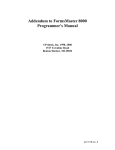
THEORY OF OPERATION
The Imager graphics coprocessor board is installed inside the printer, where it communicates directly with the main
logic of the printer. But conceptually, the Imager is a filter inserted in the pipeline between the host computer
interfaces and the printer.
Serial
Interface
Parallel
Interface
Imager
Coprocessor
FormsMaster
Processor
Optional
Interface
As a filter, the Imager will simply pass all data received on through to the printer, until it receives special image
commands telling it to do otherwise. The image commands will be filtered out, processed, and when necessary
replaced with native printer commands (ASCII control codes and escape sequences; in particular, graphics escape
sequences).
A cornerstone to the operation of the Imager is the use of the image control character. This special character signals
the Imager when an image command may have been encountered in the incoming data. In the event that the user
cannot use the default image control character, the control character may be changed to a different character. This may
be done through the printer's control panel or by sending the Imager a special command to change the control
character. The Imager is "passive" to data which it receives from the host device until the image control character is
encountered. That is, it simply sends all data it receives to the printer logic for printing until it receives a control
character. If a control character is encountered in the incoming data, the Imager examines the two characters
following the control character. If those two characters form the "activation" command, then the Imager will begin
1
I N T R O D U C T I O N
analyzing all incoming data for other special commands. If those two characters do not form the "activation"
command, then no other action is taken on the incoming data and the data is simply passed on to the printer for
printing.
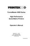
The Imager operates in three different "modes" or levels of processing: pass-thru mode, filter mode, and image mode.
Each mode represents a distinct level of operation where certain sequences of characters are interpreted as
"commands". The action taken by the Imager when a command is encountered depends on which mode is active at
the time. Typically, when a printer equipped with the Imager is powered on, pass-thru mode will be active. When the
appropriate command is received by the Imager (while in pass-thru mode), it will activate filter mode. With filter
mode active, other commands may be received which will either cause processing of data, change to image mode or
change back to pass-thru mode . Each mode provides a different level and type of processing activity.
Pass-Thru Mode
Filter Mode
Image Mode
Briefly, when the ^PY command is received in pass-thru mode, then filter mode will be activated. When the ^M
command is received in filter mode, then image mode will be activated. These commands, and many others, are
discussed in more detail later in this manual.
NOTATIONS AND CONVENTIONS
All hexadecimal numbers use the suffix character 'h' to distinguish them from decimal numbers (e.g. 5Eh is equivalent
to 94 decimal).
All measurements required by the Imager in filter mode and image mode are specified in tenths of an inch and/or dots.
The Imager board creates images based upon 60 dots per inch horizontally and 72 dots per inch vertically. All
references to tenth inches horizontally are true tenth inches (6/60 of inches). All references to tenth inches vertically
are, in reality, 7/72 of inches.
The Imager command set allows it to be fully controlled and utilized using only printable ASCII characters. ASCII
control codes are not part of the Imager command repertoire. Imager commands are introduced by the image control
character, which is by default the printable ASCII caret ('^') character (94 decimal, 5E hex). Some people may refer to
the caret character as the "hat" character.
Note in particular that the ESC control code (27 decimal, 1B hex) is not a part of the Imager command set. When the
caret ('^') character is seen in this manual, it does not mean ESC and it does not mean "control-_" !
The use of image commands is illustrated throughout this manual. In these illustrations, commentary is provided at the
far right as italicized text. For example:
^PY^-
activate filter mode
^F
eat all carriage control
^PN^-
return to pass-thru mode
These italicized comments are not part of the image commands, and should not be appended to the image commands
being described. The comments are provided only to improve the reader's understanding of what the image
commands are doing.
2
I N T R O D U C T I O N
The Reference Section of this manual contains a detailed description of the command format for each command. For
example:
^Hnn
where:
nn = New universal height in 1/10 inches; two digits from 00 to 99.
Characters in the command that must be typed exactly as shown (^H) are not italicized. Parameters that must be filled
in (nn) are italicized. The italicized characters serve only as place holders for the actual values that will be specified.
Note also that the exact number of characters required have been reserved. The use of nn, for example, implies that
two digits must be specified. If necessary, use a leading zero (3/10 inches would be specified as "03", not as '3').
3
Imager Setup
This section describes the various FormsMaster control panel settings which affect the operation of the Imager.
Although it may be necessary to modify some Imager setup parameters, there is a good chance that the Imager will
work perfectly with the factory default values. You may want to try your printer as it is before changing any values.
If you are not already familiar with how to use the Setup features of the printer, please refer to the “Introduction to
Setup” section “Printer Configuration” chapter of the FormsMaster 8000 Series Operator’s Manual. To access the
following items, use the SETUP button to access the INTERFACE MENU, and press the SUBMENU button until Imager is
displayed as shown below. The remainder of this section described the different items which may be set for the
Imager and the possible values for each.
INTERFACE MENU
Imager
Emulation
Emulation
QMS CodeV v2
Possible Values: QMS CodeV v2*, PTX CodeV v2
This item sets the Imager emulation mode. QMS CodeV v2 selects QMS Code V version 2. PTX CodeV v2 selects
the Printronix version of QMS CodeV version 2.
Control Character
ControlCharacter
^ (5E Hex)
Possible Values: ^ (5E Hex)*
SOH (01 Hex) through HT (09 Hex),
SO (0E Hex) through (FF Hex)
This item sets the control character used to begin commands. The character normally used for QMS is the caret (^).
Line Terminator
Line Terminator
LF
Possible Values: LF*, CR
This item specifies a carriage return or line feed as the line terminator . This allows the user to dictate which character
(a carriage return or a line feed) will be the last character on a line. The user should check the host device (computer)
attached to the printer to determine what this setting should be.
5
I M A G E R
S E T U P
Bar Code Density
Bar Code Density
High-Res
Possible Values: Low-Res, Medium-Res, High-Res*,
Graphics Med-Res
This item sets the density, or graphics resolution, for bar codes. Typically the higher the resolution, the higher the
quality of the bar code. However, for printing large bar codes that will be read from a distance, lower resolution will
still provide good readability and provide faster throughput.
QMS Character Set
Possible Values: USA
United Kingdom
Sweden/Finland
Norway/Denmark
Japan
Germany
QMS Char Set
USA
France
Italy
Spain
PC Subset
CodeV Version1
This item selects the character set as described.
^PY Translation Mode
^PY Translation
Not Active
Possible Values: Not Active*, Active
This item selects whether or not ^PY Filter Mode translation processing is active at power on or reset. If this
parameter is set to Active, the Imager will power-up in filter mode. If filter mode is made active this way, it cannot
be disabled by issuing the ^PN "filter mode termination" command.
^F Free Format Mode
^F Free Format
Not Active
Possible Values: Not Active*, Active
This item selects whether or not the ^F Free Format Mode is active in Filter Mode at power-up. The value of this
parameter does not become meaningful unless the ^PY "Translation" parameter discussed above is set to Active or
unless a ^PY command is received in the data stream. Once this command becomes active, all carriage control
characters (carriage return, line feed and form feed characters) are ignored by the Imager. This setting will remain
active until the filter mode command ^O is encountered in the incoming data stream or until the ^PN "filter mode
termination" command is encountered.
^ X Ignore Data Mode
^X Ignore Data
Not Active
Possible Values: Not Active*, Active
This item selects whether the ^X ignore character mode is active. When Active, all incoming data will be ignored
until the ^A command is received. This command is not meaningful unless the ^PY Translation Mode parameter is set
to Active. This setting may be useful on systems where the host computer sends banner pages to the printer before
the user application can send print information to the printer.
6
I M A G E R
Imager Zero Style
S E T U P
Imager Zero
Slashed
Possible Values: Slashed*, Normal
This is not a valid item for the Imager image mode fonts. (It selects the type of zero character (Ø or O) to be printed
by the ImagerPlus only). For printer fonts printed in pass-thru mode or filter mode, a similar parameter is available for
each form in the "FORMS MENU".
Line Registration
LineRegistration
Not Maintained
Possible Values: Not Maintained*, Maintained
This item selects whether or not the form will automatically be advanced to the next line boundary when Filter Mode
is exited.
Vertical DPI Resolution
Vertical DPI
72
Possible Values: 72*, 70
This item sets the vertical resolution to 72 or 70 Dots Per Inch.
Vertical Text Spacing
Vertical Text SP
Version 2
Possible Values: Version 2*, Version 1
This item selects whether text should be spaced vertically as in Code V version 1 or version 2.
Code V Space Fields
CodeV SP Fields
Process
Possible Values: Process*, Ignore
This item selects whether Code V space fields should be processed.
7
Imager Overview
PASS-THRU MODE
In pass-thru mode, passive, non-translation printing occurs. The print operations may include text and or graphics
printing which is native to the FormsMaster 8000/8003. Reports, listings, spread-sheets, and graphics software
packages would be typical applications that would be used with pass-thru mode printing. In pass-thru mode, all printer
action will occur as though there is no Imager board resident in the printer. The Imager simply allows all incoming
data to be passed on to the printer without changing anything in the print data stream.
FILTER MODE
In filter mode, the Imager intercepts information and performs operations on the incoming data before printing occurs.
Filter mode is activated by the occurrence of the "filter mode activation" command, ^PY. Filter mode is deactivated
by the occurrence of the "filter mode deactivation" command, ^PN. When filter mode is deactivated, the printer
returns to pass-thru mode. Primarily, filter mode commands are used to "manipulate" the incoming data streams
before they are printed. Filter mode commands do not actually perform graphics functions; those functions are
handled by image mode commands.
IMAGE MODE
Image mode commands are used to define graphic images such as bar codes or Imager font text characters. The ^M
command is an image prefix which will activate image mode. There are three commands (^*, ^-, and ^,) which will
terminate image mode and return to filter mode; each one is a pass terminator. An image sequence is initiated by the
^M command that activates image mode; the sequence includes all of the image commands that are processed before
returning to filter mode. All of the graphic images defined by the image sequence constitute the image pass; the pass
will be printed upon receipt of the pass terminator (^*, ^-, or ^,).
PROCESSING CHARACTERISTICS
The default image control character is the caret ('^') character. Although this character may be changed to a different
character by the user, throughout this document, the control character will be referenced as the caret ('^') character.
The only valid command which is recognized in pass-thru mode is the "filter mode activation" command, ^PY. Until
this command is encountered, the Imager will pass all incoming data to the printer. There is no assumption on the part
of the Imager as to the type of data being sent to the printer. It may be either text or graphics data.
After the "filter mode activation" command is encountered, the Imager will examine all incoming data for other filter
mode commands. If filter mode commands are encountered, the commands will be operated on as defined by the
commands' syntax. If a carriage return and/or a line feed character occurs within four character positions following the
"filter mode activation" command, they will be absorbed by the Imager. Otherwise, the carriage return and/or the line
feed characters will be passed on to the printer for the printer to process.
Once filter mode is active, the "image mode activation" command (^M) will activate image mode. The printing of all
Imager font characters and bar codes occurs in image mode. Printing is done in passes. A pass may be very simple,
printing only a single character, or may be very complex, printing a series of labels containing fixed and variable data.
9
I M A G E R
O V E R V I E W
Printing does not occur until the pass is completed by a pass terminator. The pass terminator (^*, ^-, or ^,) forces
printing to occur, terminates image mode, and returns to filter mode.
When the "filter mode termination" command ^PN is encountered while the Imager is in filter mode, the active filter
mode commands will finish processing and the Imager will then return to pass-thru mode.
QMS MAGNUM AND IMAGER DIFFERENCES
Several bar code symbologies are considered proprietary or are no longer in active use. The Imager does not support
those bar codes.
Several bar codes found in the QMS Magnum Code V which are not supported by the Imager include: AGES, Delta
Distance A, Matrix 2 of 5, MRC Edge Code, Rapistan and Identicon 2 of 5.
Bar codes which are supported include: Code 39, Codabar, MSI, Interleaved 2 of 5, UPCA 11 digit, UPCE 10 digit,
UPCE0 6 digit, UPCE1 6 digit, EAN 13, EAN 8, Code 128, UCC-128 and PostNet.
UCC-128 and PostNet are not a QMS Code V feature but they have been added to the Imager.
PERFORMANCE CONSIDERATIONS
Text can be printed in pass-thru mode, filter mode or image mode. Printing text (or anything else for that matter) in
pass-thru mode does not use any of the capabilities of the Imager; all printed images are handled by the printer's
resident emulation. Since pass-thru mode printing does not actually use the Imager capabilities, only filter mode and
image mode will be discussed.
Text which is printed in filter mode uses normal printer fonts. The Imager fonts can only be used in image mode. If
the user has the option of printing in either filter mode or image mode and can use the fonts available in either mode,
then better performance will be achieved by printing in filter mode. The main reason for this is that filter mode text is
printed in a "non-graphics" mode where image mode text is printed in a "raster graphics" mode. In filter mode, the
printer can skip blank areas between lines of text. In image mode, the blank areas as well as the text are printed.
Generally speaking, for this reason, graphics images do not print as quickly as straight text alone.
LABEL DESIGN CONSIDERATIONS
It is a good idea to know what a label is to look like before coding it for printing. Sketching the label on graph paper
or better yet, a printer layout sheet before coding begins can eliminate a lot of time in the design process. A ruler with
1/10 inch, 1/6 inch and 1/8 inch markings will also be very handy. Label stock selection criteria should include:
material makeup of the label which will work well with the printer, label size based on standard units (1/10 inches
horizontal and 1/6 or 1/8 inches vertical) plus any other issues which are required to satisfy the printing requirements.
Before coding of a label begins, one of two different implementation methods should be decided upon. The Imager
has two different methods for processing a label image:
•
Buffered Overlay
•
In-line Coding
When the buffered overlay method is used, the Imager will "save" the commands for printing a label image and store
them. Then the user can simply send the data down to "fill in" the labels with variable data. The in-line coding
method involves the repetitive transmission of commands to the Imager to print label images. Many previously
designed labels use the in-line coding method. The primary reason for this was the limited memory space available on
the older printer controllers; only small labels could use the buffered overlay method. Today, however, lack of
memory space is not as big a problem as it once was. It is recommended that when designing and coding a label, the
buffered overlay method be used whenever possible. There are two main reasons for this recommendation: First, the
10
I M A G E R
O V E R V I E W
volume of data (characters) transmitted to the printer is considerably less when the buffer overlay method is used. The
label image only has to be sent one time. Thereafter, only data to fill it out is necessary. Second, the code is easier to
maintain because the label commands are generated at one time and do not have to be interspersed with the data at
print time by the user.
If the labels do not need to be "filled out" with variable data, then the buffered overlay method would probably not be
necessary. This would include labels which may only be printed one time or labels which have incrementing or
decrementing serial numbers and which utilize the Imager "repeat loop" command.
BUFFERED OVERLAY OVERVIEW
Label printing almost always starts with the ^PY command. This command informs the Imager to make the filter
mode and image mode commands available for use. The second command will normally be a ^F command. This tells
the Imager to "eat" any carriage control character which it may encounter. This command is especially useful with
systems which automatically generate carriage control commands with each line sent to the printer. With this
command, the label designer has direct control over the movement of the label or paper in the printer. If the ^F
command is used, then the only way carriage returns, line feeds and form feeds will occur is if the designer programs
them in with the ^-, ^* and ^, "printer control" commands.
A typical buffered overlay label would have the following generalized format:
^PY^-
turn image processing ON
^F
turn free format processing ON
^B
start buffer overlay definition
(text and graphics label definitions)
^]
end of buffer overlay definition
(variable data fields to "fill-out" the label)
^G
end of the variable data
^O
turn free format processing OFF
^PN^-
turn image processing OFF
The "text and graphics label definitions" shown in the example may be made up of filter mode commands or printable
text or image mode commands. The "variable data fields" are simply a list of data which will be mapped into
predefined locations in the label image when it prints. More information concerning the "buffered overlay" command
is available in Filter Mode Commands in the Reference Section.
As shown in the example, it is good practice to "turn OFF" functions which have been "turned ON" in the process of
printing labels. This will leave the printer in a known state when a job completes and the printer will be ready for the
next print job. Failure to deactivate certain functions after they have been activated can cause "mysterious" problems
for the next job or user of the printer.
11
Basic Commands
The Imager command set allows it to be fully controlled and utilized using only printable ASCII characters. Image
commands may be generated by a specially designed program, written in whatever programming language is
convenient. Or, image commands may simply be placed in a file created with a standard text editor or word processor.
When generating image commands, it will be helpful to keep the following points in mind.
Image commands are case sensitive. There is a difference between upper-case and lower-case letters in image
commands. In most commands, upper-case letters are required.
If a command accepts parameters, there usually are no default values, so the parameters must be specified. When
specifying parameters, the exact number of characters (including leading zeros) must appear in the command
sequence.
Spaces may not be embedded within a command sequence (unless they are data to be printed).
TURNING THE IMAGER ON AND OFF
In pass-thru mode, the Imager simply passes all data received on through to the printer. This may be thought of as
passive processing, or you may think of the Imager as being turned off. Placing the Imager in filter mode enables
translation processing, and may be thought of as turning it on.
Sending the command ^PY to the printer will activate filter mode. Sending the command ^PN will deactivate filter
mode and return to pass-thru mode.
Some special rules should be followed when coding the ^PY command:
•
The ^PY command must be the first printable characters (preceding spaces do not count) on a new line to be
recognized.
•
The ^PY command should be terminated by a filter mode carriage return, ^- (hat-dash).
•
The ^PY^- sequence should be terminated by an ASCII control character, i.e. carriage return or line feed. If a
carriage return and/or line feed occurs within four character positions following the ^PY command, they will be
absorbed by the Imager, and no paper motion will occur. Otherwise, the carriage return and/or the line feed
characters will be passed on to the printer for the printer to process.
Filter mode may also be activated by specifying "Translation: On" in the "Setup: Options" menu on the printer's
control panel. If "Translation: On" has been set, the Imager will be initialized to filter mode at power-up or printer
reset. In this case, the ^PN command will not reset the Imager to pass-thru mode; that can only be accomplished by
changing the "Translation" value through the printer's control panel.
FREE FORMAT
Free format disables the processing of control codes (ASCII codes 00h to 1Fh). All carriage-control commands, such
as carriage return, line feed, and form feed, will be absorbed so they will not be acted upon by the printer.
Some operating systems and application software may automatically generate certain control codes in the data stream.
Unexpected control codes could prematurely terminate the pass, cause undesired paper motion, etc. Free format will
avoid these problems.
13
B A S I C
C O M M A N D S
Free format also allows the programmer to separate image commands with line breaks, to greatly increase readability.
With free format on, image commands on consecutive lines within a file are treated as a single command line. A pass
terminator ends the command line.
Since free format causes all control characters to be ignored, the programmer must explicitly provide for forms control
(line feed, form feed, etc.) with the appropriate image commands.
Free format is enabled by the ^F command, and disabled by the ^O command. Free format is also disabled when the
^PN command is used to turn the Imager off.
IGNORE CHARACTER
The ^X command will cause all subsequent characters to be ignored, until a ^A command is received. If a ^A
command is never received, then none of the incoming data will be processed or printed. Use of the ignore character
command is illustrated below:
^X this text is absorbed (eaten) ^A and this data is printed.
Ignore character may be useful if a word processor or programming language is sending undesired characters to the
printer. Ignore character may also be used to embed comments among image commands:
^PY^-
activate filter mode
^F
eat all carriage control
^X
begin ignoring characters
This is a comment
the comment line will not be printed
^A
stop ignoring characters
^PN^-
return to pass-thru mode
When debugging Imager code, ignore character may be used to comment out certain lines of code while other lines are
being debugged.
CHANGING THE IMAGE CONTROL CHARACTER
Some applications require use of the caret ('^') character, which is the default image control character for image
commands.
The ^Nc command may be used to change the image control character to any other printable character, c. For
example, the command ^N~ would change the image control character to a tilde. If you change the image control
character, be sure that all subsequent image commands use the new control character. If an inappropriate character
(i.e. one that appears in the data stream for other reasons) is set as the image control character, unpredictable printing
results will occur.
The default image control character may be changed via the printer's control panel, by changing the "Control Char"
value in the "Setup: Options" menu.
14
B A S I C
C O M M A N D S
PRINTING THE IMAGE CONTROL CHARACTER
The image control character may be printed by selecting a new image control character, printing the old control
character, and then changing back to the old control character. The image command sequence "^N~^~N^" will print
as the single character '^'.
PRINTING NORMAL CHARACTERS
Normal characters, using the resident printer fonts and printing at the normal character print speeds, can be printed in
pass-thru mode and filter mode.
Printing text (or anything else for that matter) in pass-thru mode does not use any of the capabilities of the Imager; all
printed images are handled by the printer's resident emulation. All data is simply passed through the Imager to the
printer.
Text which is printed in filter mode also uses the resident printer fonts and normal character print speeds, but a new
wrinkle is added because translation processing has been activated. If free format is off, the provided text will print "as
is". For example:
^PY^^O
First line of normal text.
Second line of normal text.
^PN^But if free format is on, an explicit line terminator command must be added at the end of each line of text. For
example:
^PY^^F
First line of normal text.^-^*
Second line of normal text.^-^*
^PN^Normal characters using the resident printer fonts cannot be printed in image mode. Any characters printed in image
mode will be generated by the Imager and printed in a "raster graphics" mode.
15
Characters
The image command ^M may also be used for printing characters. The characters may be generated in four different
pitch sizes: 7.5 cpi, 10 cpi, 12 cpi, and 15 cpi. The 7.5 cpi characters are 0.2 inch high; all of the other characters are
0.1 inch high.
Before using ^M to print characters, a ^PY command must be used to activate filter mode. A command may print any
number of characters, within the constraint that the characters must fit horizontally on the paper. Data which extends
beyond the paper will be lost. A pass terminator must be encountered before printing will actually occur.
7.5 Pitch
The following command may be used to print characters at 7.5 cpi. The characters will be 0.2 inch high. The vertical
positioning (justification) is specified, followed by the characters to be printed. The command is:
^M0000jjdc...c
where:
jjd
jj
d
c...c
= Justification from the current position. Indicates how far down
from the top of the pass the characters will begin printing.
= 1/10 inches; two digits from 00 to 99 (e.g. 10 = 1.0 inch).
= Dots (1/72 inches); one digit from 0 to 9 (e.g. 7 = 7/72 inch).
= Character or characters to be printed.
For example, "^M0000000ABCDEFGHIJKLMNOPQRSTUVWXYZ0123456789^-" will print the text string
"ABCDEFGHIJKLMNOPQRSTUVWXYZ0123456789", using a character pitch of 7.5 cpi.
10 Pitch
The following command may be used to print characters at 10 cpi. The characters will be 0.1 inch high. The vertical
positioning (justification) is specified, followed by the characters to be printed. The command format is:
^M0101jjdc...c
where:
jjd
jj
d
c...c
normal - left-to-right
= Justification from the current position. Indicates how far down
from the top of the pass the characters will begin printing.
= 1/10 inches; two digits from 00 to 99 (e.g. 10 = 1.0 inch).
= Dots (1/72 inches); one digit from 0 to 9 (e.g. 7 = 7/72 inch).
= Character or characters to be printed.
For example, "^M0101000ABCDEFGHIJKLMNOPQRSTUVWXYZ0123456789^-" will print the text string
"ABCDEFGHIJKLMNOPQRSTUVWXYZ0123456789", using a character pitch of 10 cpi.
17
C H A R A C T E R S
12 Pitch
The following command may be used to print characters at 12 cpi. The characters will be 0.1 inch high. The vertical
positioning (justification) is specified, followed by the characters to be printed. The command format is:
^M0001jjdc...c
where:
jjd
jj
d
c...c
normal - left-to-right
= Justification from the current position. Indicates how far down
from the top of the pass the characters will begin printing.
= 1/10 inches; two digits from 00 to 99 (e.g. 10 = 1.0 inch).
= Dots (1/72 inches); one digit from 0 to 9 (e.g. 7 = 7/72 inch).
= Character or characters to be printed.
For example, "^M0001000ABCDEFGHIJKLMNOPQRSTUVWXYZ0123456789^-" will print the text string
"ABCDEFGHIJKLMNOPQRSTUVWXYZ0123456789", using a character pitch of 12 cpi.
15 Pitch
The following command may be used to print characters at 15 cpi. The characters will be 0.1 inch high. The vertical
positioning (justification) is specified, followed by the characters to be printed. The command format is:
^M0100jjdc...c
where:
jjd
jj
d
c...c
normal - left-to-right
= Justification from the current position. Indicates how far down
from the top of the pass the characters will begin printing.
= 1/10 inches; two digits from 00 to 99 (e.g. 10 = 1.0 inch).
= Dots (1/72 inches); one digit from 0 to 9 (e.g. 7 = 7/72 inch).
= Character or characters to be printed.
For example, "^M0100000ABCDEFGHIJKLMNOPQRSTUVWXYZ0123456789^-" will print the text string
"ABCDEFGHIJKLMNOPQRSTUVWXYZ0123456789", using a character pitch of 15 cpi.
HIGH-RESOLUTION CHARACTERS
Six different high-resolution fonts are available through the ^S command for generating characters. Pitch sizes vary,
but all of the characters are 0.1 inch high. The OCR-A font contains only upper case characters.
Before using the ^S command to print characters, a ^PY command must be used to activate filter mode, and a ^M
command must be used to activate image mode graphics processing. Any number of characters may be printed, within
the constraint that the characters must fit horizontally on the paper. Data which extends beyond the paper will be lost.
A pass terminator must be encountered before printing will actually occur.
To change between high-resolution fonts within a sequence, just issue another ^S command. To change to standard
resolution characters, another ^M command must be issued, but it is not necessary to start a new pass.
The command format is:
^Sn
where:
18
n = Font number; one digit from 1 to 6.
C H A R A C T E R S
Font#
1
2
3
4
5
6
Font Description
10 cpi (characters per inch)
12 cpi
13.33 cpi
15 cpi
17.14 cpi
10 cpi OCR-A
For example, the command sequence "^M0101000^S6OCR-A FONT^-" will print the text string "OCR-A FONT",
using OCR-A characters at a character pitch of 10 cpi.
LOWER CASE DESCENDERS
Some lower case characters (g, j, p, q, y) have descenders which are designed to print below the font base line. The
Imager can print these characters in two different ways: aligned at the font base line, or descending the appropriate
distance below the base line.
The ^D command is used to toggle from "descenders off" to "descenders on" and vice-versa. The command format is:
^D
When image mode is activated, the pass always begins with "descenders off". The first ^D will set "descenders on".
A second ^D will set "descenders off", as will a pass terminator. The state of descenders may be toggled as many
times as necessary within the pass.
Setting "descenders on" within an image pass will produce an under-character gap that would not otherwise be
present. This is true even if no lower case characters with descenders are printed.
This command is valid for image mode graphics fonts which include the expandable characters. It does not include
the "high-resolution fonts" which are activated with the image mode ^S command. The high-resolution fonts always
print the descender characters below the font base line.
19
Bar Codes
The Imager is capable of printing many types of bar codes. Human readable text can be automatically printed beneath
bar codes.
The Imager automatically calculates and includes check digits in all bar codes that require them. The check digits are
calculated from the supplied bar code data, and included somewhere in the bar code along with the data. Check digits
are used by bar code readers to insure that a bar code has been read correctly, or to detect the input error.
The programmer can specify the height of the bar codes. The actual width of a bar code will depend upon the bar code
type and density, the data encoded, and the ratio of the bars and spaces in the bar code.
The Imager is pre-programmed with numerous bar code types, all capable of printing at the most popular ratios (see
the standard bar code table). Variable ratio bar codes may also be printed, giving an almost infinite variety of bar code
sizes.
Bar code commands must be contained within an image sequence. The prefix ^M may be used to enter image mode to
draw bar codes; the universal height or width specification will affect the "height" of bar codes.
Bar codes are drawn at the current print position. Horizontal tabbing and justification commands may be used to reach
the desired print position.
STANDARD BAR CODES
The ^B command is used for printing bar codes. The height parameter of the preceding image command (^M or ^H)
will determine the bar code height. The command format is:
^Batd...d^G
where:
a
t
d...d
^G
= Human readable autoprint indicator,
one character, valid entries are: 'Y'es, 'N'o or 'O'CR.
= Bar code type, one character, see the Standard Bar Code Table.
= Data to encode as a bar code,
a variable number of characters and/or digits.
= Bar code sequence terminator.
For example, the following Imager code:
21
B A R
C O D E S
^PY^-
activate filter mode
^F
absorb all carriage control
^L06
label height = 6 lines (1 inch)
^M05
activate image mode & height = 0.5 inches
^BYAHELLO^G
define bar code; code 39 w/autoprint
^-
terminate image mode and print
^,
issue a label-feed (form feed)
^O
turn ^F command off
^PN^-
return to pass-thru mode
Will print the following bar code:
STANDARD BAR CODE TABLE
INDEX
22
BAR CODE
CHECK DIGITS
RATIO
A
B
C
D
F
G
H
I
K
L
P
Q
R
S
T
U
X
Z
1
Code 39
Code 39
Code 39
Codabar
MSI
MSI
MSI
MSI
Interleaved 2 of 5
Interleaved 2 of 5
UPCA 11 Digit
UPCE 10 Digit
UPCE0 6 Digit
UPCE1 6 Digit
EAN 13
EAN 8
MSI
Code 128 (Auto Select A,B,C)
UCC-128
1:1:3:3
1:2:4:5
1:1:3:3
1:2:3:4:1:1:1:1
1:1:2:2
1:1:2:2
1:1:2:2
1:1:2:2
1:1:3:3
1:2:4:5
1:1:2:2:3:3:4:4
1:1:2:2:3:3:4:4
1:1:2:2:3:3:4:4
1:1:2:2:3:3:4:4
1:1:2:2:3:3:4:4
1:1:2:2:3:3:4:4
1:1:2:2
1:1:2:2:3:3:4:4
1:1:2:2:3:3:4:4
2
PostNet
None
None
Mod 43
None
None
Mod 10
Mod 10/Mod 10
Mod 11/Mod 10
None
None
Mod 10
Mod 10
Mod 10
Mod 10
Mod 10
Mod 10
Mod 11
Pseudo Mod 103
Pseudo Mod 10/
Pseudo Mod 103
Mod 10
B A R
C O D E S
VARIABLE RATIO BAR CODES
The ^B commands that is used to print standard bar codes is also used to print variable ratio bar codes. In fact, printing
variable ratio bar codes is done in an identical manner except that the desired ratio must also be specified. This ratio
will override the default ratio that is normally used to print the standard bar code. The height of the bar code will be
determined by the preceding image commands. The command format is:
^Ba9tr...rd...d^G
where:
a
9
t
r...r
d...d
^G
= Human readable autoprint indicator,
one character, valid entries are: 'Y'es, 'N'o or 'O'CR.
= '9' indicating a user defined ratio follows.
= Bar code type, one character, see the Standard Bar Code Table.
= User defined ratio; a variable number of digits,
depending on bar code type, each digit from 1 to F.
= Data to encode as a bar code,
a variable number of characters and/or digits.
= Bar code sequence terminator.
The r...r ratio is specified in pairs of digits representing bar/space ratios. The number of digits that must be specified
depends on the bar code type; it will be the same as the number of digits in the default ratio in the Standard Bar Code
Table. For example, code 39 requires the specification of four digits, representing the width of narrow bars, narrow
spaces, wide bars, and wide spaces respectively.
For example, the following Imager code:
^PY^-
activate filter mode
^F
absorb all carriage control
^L06
label height = 6 lines (1 inch)
^M05
activate image mode & height = 0.5 inches
^BY9A1234HELLO^G
define bar code; code 39 w/ratio 1:2:3:4
^-
terminate image mode and print
^,
issue a label-feed (form feed)
^O
turn ^F command off
^PN^-
return to pass-thru mode
Will print the following bar code:
23
B A R
C O D E S
SPECIAL AUTOPRINT OPTIONS
The bar code command (^B) usually uses a 'Y' or 'N' to indicate autoprinting of human readable text under a bar code.
Several additional options are available.
If a number from '1' to '6' is used instead of the 'Y', then the high-resolution font corresponding to the ^S font select
command will be used. For example, the sequence "^M05^B1A12345^G^-" will print the following bar code, using
high-resolution 10 cpi characters for autoprint.
It is also possible to force the autoprint characters to print above or below the bar code. The autoprint characters print
below the bar code by default. If the 'Y' is preceded by an 'A', the characters will print above the bar code. For
example, the sequence "^M05^BAYA12345^G^-" will print the following bar code.
BAR CODE SYMBOLOGIES
A bar code is a graphical representation of characters. A bar code symbol contains a sequence of varying width bars
and spaces representing the characters encoded in the bar code. The actual pattern necessary to encode a particular
character is dependent upon the type of bar code. The length of a bar code is dependent upon the type of bar code, the
number of data characters encoded, and the bar/space ratios.
Different bar code symbologies support different character sets. Numeric symbologies can encode only numbers.
Other symbologies can encode alphanumeric characters, and some can encode the entire ASCII character set.
Bar code symbologies may be discrete or continuous. In a discrete code, each character can stand alone and be
decoded independently from the adjacent characters. Each character begins and ends with a bar, and is separated from
its neighbor by a loosely toleranced intercharacter gap that contains no information. In a continuous code, each
character begins with a bar and ends with a space. The end of one character is indicated by the start of the next
character. There are no intercharacter gaps. A continuous code is denser, requiring less symbol length to encode a
given amount of data.
A bar code symbol encodes data in the widths of the bars and spaces. A bar code symbology may employ only two
element widths (wide and narrow), or may employ multiple widths. The widths of the elements are specified relative
to the nominal width of the narrow elements (both bars and spaces). For example, a bar code with ratio 1:1:3:3
(narrow bar : narrow space : wide bar : wide space) has wide elements that are three times the width of the narrow
elements.
Some bar code symbologies are designed to encode data of a fixed length. Others should be used only in a fixed
length environment because of data security reasons (a partial scan may appear to be valid). Some symbologies can
safely encode variable length data.
Bar code symbologies differ in the amount of data that can be encoded in a given distance. When comparing the
relative densities of different symbologies, it is customary to compare codes printed with the same nominal width
narrow elements.
24
B A R
C O D E S
A symbology is considered to be self-checking if a single printing defect will not cause a character to be transposed
into another valid character in the same symbology.
A start code is a particular pattern of bars and spaces placed at the beginning of a bar code to indicate to the scanner
where the symbol begins. A stop code is a pattern placed at the end of a bar code to indicate where the symbol ends.
The start and stop codes may also indicate the direction of the scan.
A check character may be placed in a predetermined position in a bar code symbol. The value of the check character
is mathematically calculated from the other characters encoded in the symbol. The scanner uses the check character to
validate that correct data has been decoded. If the check character can only assume numeric values (0-9), it is often
called a check digit.
All bar codes require a quiet zone at each end to permit a scan to begin and end in a blank area. The quiet zones
should be at least 0.25 inches wide and be completely blank to allow accurate reading of the start/stop codes and to
prevent adjacent bar codes from overlapping. The programmer is responsible for providing adequate quiet zones
when printing bar codes.
The different bar code symbologies supported by the Imager are described below. The description includes start and
stop codes, valid character set, the data field, check digits, and any other information necessary for the creation of valid
bar codes.
Code 39
Code 39 was the first alphanumeric symbology to be developed. It is widely used, having become the de facto
standard for non-retail bar codes. It is a discrete, self-checking, variable length symbology.
An asterisk (*) is used for the start and stop code. They will be included automatically by the Imager; they should not
be included in the data field by the programmer.
The Code 39 character set contains 43 characters: 0-9, A-Z, -, ., $, /, +, %, and space. All characters are constructed
from five bars and four intervening spaces. Of these nine elements, three are wide and six are narrow. A bar code
may contain from 1 to 40 characters.
Code 39 may be printed with or without a check digit. Code 39 type C (see the Standard Bar Code Table) includes a
modulo 43 check digit, which is automatically generated by the Imager.
Code 39 bar codes require a four digit ratio, with the digits representing: narrow bar, narrow space, wide bar, wide
space.
For example, the command sequence "^M05^BYA12345^G" will generate the following bar code, using the default
ratio of 1:1:3:3.
The command sequence "^M08^BY9A226612345^G" will generate the following bar code, using double the default
ratio.
The command sequence "^M05^BYC12345^G" will generate the following bar code, containing an automatically
generated modulo 43 check digit.
25
B A R
C O D E S
Codabar
Codabar is commonly used in libraries, blood banks, and air parcel express applications. It is a discrete, self-checking,
variable length symbology.
Four start/stop code characters (A, B, C, D) are available in any combination as start/stop codes. The start and stop
code characters must be included as part of the data field to be produced with the bar code.
The Codabar character set contains 16 characters: the digits 0-9, and the characters $, :, /, ., +, -. All characters are
constructed from four bars and three intervening spaces. A bar code may contain from 1 to 40 characters.
Codabar bar codes require an eight digit ratio, with the digits representing: narrow bar, narrow space, wide bar, wide
space, ignored, intercharacter gap, ignored, ignored.
For example, the command sequence "^M05^BYDA1234B^G" will generate the following bar code, using the default
ratio of 1:2:3:4:1:1:1:1.
The command sequence "^M08^BY9D24681211A2468B^G" will generate the following bar code, using double the
default ratio.
MSI
MSI Code is primarily used for the marking of retail shelves. It is a derivative of Plessey Code, which is a "pulse
width modulated" code. MSI symbols are variable length, low density, continuous, and not self-checking.
The MSI character set contains the ten digits 0-9. Each character consists of four bars and four spaces, with each barspace pair representing one bit of information. Zero bits consist of a narrow bar followed by a wide space. One bits
consist of a wide bar followed by a narrow space. An MSI symbol includes a start code, data characters, optionally
one or two check digits, and a stop code. The start code, stop code, and check digit(s) will be included automatically
by the Imager. A bar code may contain from 1 to 40 digits.
MSI bar codes require a four digit ratio, with the digits representing: narrow bar, narrow space, wide bar, wide space.
For example, the command sequence "^M05^BYG0123456789^G" will generate the following bar code, using the
default ratio of 1:1:2:2.
26
B A R
C O D E S
The command sequence "^M08^BY9G22440123456789^G" will generate the following bar code, using double the
default ratio.
Interleaved 2 of 5
Interleaved 2 of 5 is a high density, continuous, self-checking, variable length numeric symbology. It is used primarily
in the distribution industry.
The start code consists of two narrow bars and two narrow spaces. The stop code consists of one wide bar, a narrow
space, and a narrow bar. They will be included automatically by the Imager.
The Interleaved 2 of 5 character set contains the ten digits 0-9. Each Interleaved 2 of 5 character actually encodes two
digits; one in the bars and one in the spaces. There are five bars, two of which are wide and three of which are narrow.
Likewise, there are five spaces, two of which are wide and three of which are narrow. All of the odd-positioned digits
are encoded in the bars, and all of the even-positioned digits are encoded in the spaces. The interleaving process
requires an even number of digits. If an odd number of digits is specified, a leading zero is automatically inserted by
the Imager. A bar code may contain from 1 to 40 digits.
Interleaved 2 of 5 bar codes require a four digit ratio, with the digits representing: narrow bar, narrow space, wide bar,
wide space.
For example, the command sequence "^M05^BYK123456^G" will generate the following bar code, using the default
ratio of 1:1:3:3.
The command sequence "^M08^BY9K2266123456^G" will generate the following bar code, using double the default
ratio.
A partial scan (a scan that does not include both quiet zones) of an Interleaved 2 of 5 bar code has a high probability of
decoding as a valid, but shorter symbol. This is due to the simple structure of the start and stop codes -- a partial scan
of an Interleaved 2 of 5 digit can appear to be a start or stop code. Because of this, Interleaved 2 of 5 is best used in a
fixed length application, where the scanner is programmed to look for a specific number of digits. Leading zeros may
be added to maintain fixed length strings.
Another alternative is to add protection stripes, also called bearer bars, to the top and bottom of the Interleaved 2 of 5
bar code. These prevent a partial scan from being decoded as a valid symbol. The following code will generate an
Interleaved 2 of 5 bar code with bearer bars.
27
B A R
C O D E S
^PY^-
activate filter mode
^F
turn free format on
^M10^KF
activate image mode, 1.0 inch height, hi-res on
^T0000^J000^LS01730004
print top bearer bar
^T0003^J000^BYK0123456789^G
print bar code
^T0000^J083^LS01730004
print bottom bearer bar
^KF^-
hi-res off
^O
turn free format off
^PN^-
return to pass-thru mode
UPCA 11 Digit
The Universal Product Code (UPC) has been used in the supermarket industry since 1973. It is a fixed length,
continuous, numeric symbology. There are three versions of the UPC symbol: Version A, which encodes 12 digits;
Version E, which encodes six digits; and Version D, which encodes variable length data. Version D is rarely used,
and is not supported by the Imager.
A UPC Version A symbol consists of a left guard pattern, six numeric digits, a center guard pattern, six more numeric
digits, and a right guard pattern. The first digit is the UPC number system digit. The next five digits are the UPC
manufacturer's code. The following five digits are the UPC product code. The last digit is a modulo 10 check digit.
For the UPCA 11 Digit bar code (type P), the programmer must specify exactly 11 digits, representing the number
system, manufacturer's code, and product code. The Imager will automatically generate the left, center, and right
guard patterns, as well as the modulo 10 check digit.
The UPC symbology uses multiple element widths to encode characters. Each character has seven modules, which
may be either black or white, to create two bars and two spaces of varying width. UPC bar codes require an eight digit
ratio, with the digits representing:
•
•
•
•
•
•
•
•
1 module wide bar
1 module wide space
2 module wide bar
2 module wide space
3 module wide bar
3 module wide space
4 module wide bar
4 module wide space.
For example, the command sequence "^M05^BYP01234567890^G" will generate the following bar code, using the
default ratio of 1:1:2:2:3:3:4:4.
28
B A R
C O D E S
The command sequence "^M08^BY9P2244668801234567890^G" will generate the following bar code, using double
the default ratio.
UPCE 10 Digit
The Universal Product Code (UPC) has been used in the supermarket industry since 1973. It is a fixed length,
continuous, numeric symbology. There are three versions of the UPC symbol: Version A, which encodes 12 digits;
Version E, which encodes six digits; and Version D, which encodes variable length data. Version D is rarely used,
and is not supported by the Imager.
UPC Version E bar codes are special zero-suppressed Universal Product Codes that compress 10 data characters down
to six characters using specific rules. A UPC Version E symbol consists of a left guard pattern, six numeric digits, and
a right guard pattern.
For the UPCE 10 Digit bar code (type Q), the programmer must specify exactly 10 digits, representing the
manufacturer's code and product code. The Imager will automatically compress these 10 digits to six digits, generate
the left and right guard patterns, and implicitly encode the number system digit (always a zero) and the modulo 10
check digit in the bar code.
The UPC symbology uses multiple element widths to encode characters. Each character has seven modules, which
may be either black or white, to create two bars and two spaces of varying width. UPC bar codes require an eight digit
ratio, with the digits representing:
•
•
•
•
•
•
•
•
1 module wide bar
1 module wide space
2 module wide bar
2 module wide space
3 module wide bar
3 module wide space
4 module wide bar
4 module wide space.
For example, the command sequence "^M05^BYQ1230000064^G" will generate the following bar code, using the
default ratio.
UPCE0 6 Digit
The Universal Product Code (UPC) has been used in the supermarket industry since 1973. It is a fixed length,
continuous, numeric symbology. There are three versions of the UPC symbol: Version A, which encodes 12 digits;
29
B A R
C O D E S
Version E, which encodes six digits; and Version D, which encodes variable length data. Version D is rarely used,
and is not supported by the Imager.
UPC Version E bar codes are special zero-suppressed Universal Product Codes that compress 10 data characters down
to six characters using specific rules. A UPC Version E symbol consists of a left guard pattern, six numeric digits, and
a right guard pattern.
For the UPCE0 6 Digit bar code (type R), the programmer must specify exactly six digits. These digits represent the
manufacturer's code and product code, but have already been compressed from 10 digits to six digits. The Imager will
automatically generate the left and right guard patterns, and implicitly encode the number system digit (always a zero)
and the modulo 10 check digit in the bar code.
The UPC symbology uses multiple element widths to encode characters. Each character has seven modules, which
may be either black or white, to create two bars and two spaces of varying width. UPC bar codes require an eight digit
ratio, with the digits representing:
•
•
•
•
•
•
•
•
1 module wide bar
1 module wide space
2 module wide bar
2 module wide space
3 module wide bar
3 module wide space
4 module wide bar
•4 module wide space.
For example, the command sequence "^M05^BYR123643^G" will generate the following bar code, using the default
ratio.
UPCE1 6 Digit
The Universal Product Code (UPC) has been used in the supermarket industry since 1973. It is a fixed length,
continuous, numeric symbology. There are three versions of the UPC symbol: Version A, which encodes 12 digits;
Version E, which encodes six digits; and Version D, which encodes variable length data. Version D is rarely used,
and is not supported by the Imager.
UPC Version E bar codes are special zero-suppressed Universal Product Codes that compress 10 data characters down
to six characters using specific rules. A UPC Version E symbol consists of a left guard pattern, six numeric digits, and
a right guard pattern.
For the UPCE1 6 Digit bar code (type S), the programmer must specify exactly six digits. These digits represent the
manufacturer's code and product code, but have already been compressed from 10 digits to six digits. The Imager will
automatically generate the left and right guard patterns, and implicitly encode the number system digit (always a one)
and the modulo 10 check digit in the bar code.
The UPC symbology uses multiple element widths to encode characters. Each character has seven modules, which
may be either black or white, to create two bars and two spaces of varying width. UPC bar codes require an eight digit
ratio, with the digits representing:
30
B A R
•
•
•
•
•
•
•
•
C O D E S
1 module wide bar
1 module wide space
2 module wide bar
2 module wide space
3 module wide bar
3 module wide space
4 module wide bar
4 module wide space.
For example, the command sequence "^M05^BYS123643^G" will generate the following bar code, using the default
ratio.
EAN 13
The European Article Numbering system (EAN) is a superset of UPC, and is the international standard bar code for
retail food packages. An EAN scanner can decode UPC, but a UPC scanner typically cannot decode EAN. Like
UPC, EAN is a fixed length, continuous, numeric symbology.
An EAN 13 symbol consists of a left guard pattern, six numeric digits, a center guard pattern, six numeric digits, and a
right guard pattern. An EAN 13 symbol contains the same number of bars as UPC Version A, but encodes a thirteenth
digit into the parity pattern of the left six digits. Two digits are used as flag digits to represent a country code, and one
digit is a modulo 10 check digit. The programmer must specify exactly twelve digits. The Imager will automatically
generate the guard patterns and the check digit.
The EAN symbology uses multiple element widths to encode characters. Each character has seven modules, which
may be either black or white, to create two bars and two spaces of varying width. EAN bar codes require an eight digit
ratio, with the digits representing:
•
•
•
•
•
•
•
•
1 module wide bar
1 module wide space
2 module wide bar
2 module wide space
3 module wide bar
3 module wide space
4 module wide bar
4 module wide space.
For example, the command sequence "^M05^BYT123456123456^G" will generate the following bar code, using the
default ratio.
31
B A R
C O D E S
EAN 8
The European Article Numbering system (EAN) is a superset of UPC, and is the international standard bar code for
retail food packages. An EAN scanner can decode UPC, but a UPC scanner typically cannot decode EAN. Like
UPC, EAN is a fixed length, continuous, numeric symbology.
An EAN 8 symbol consists of a left guard pattern, four numeric digits, a center guard pattern, four numeric digits, and
a right guard pattern. The eight numeric digits that are encoded include two flag digits that represent a country code,
five data digits, and one modulo 10 check digit. The programmer must specify exactly seven digits. The Imager will
automatically generate the guard patterns and the check digit.
The EAN symbology uses multiple element widths to encode characters. Each character has seven modules, which
may be either black or white, to create two bars and two spaces of varying width. EAN bar codes require an eight digit
ratio, with the digits representing:
•
•
•
•
•
•
•
•
1 module wide bar
1 module wide space
2 module wide bar
2 module wide space
3 module wide bar
3 module wide space
4 module wide bar
4 module wide space.
For example, the command sequence "^M05^BYU4015347^G" will generate the following bar code, using the default
ratio.
Code 128 A/B/C
Code 128 is a very high density, continuous, self-checking, variable length alphanumeric symbology. The Code 128
symbology is capable of encoding:
•
•
•
•
•
the full 128 character ASCII character set
four function code characters (FNC1, FNC2, FNC3, FNC4)
four code set selection characters (Code A, Code B, Code C, Shift)
three start characters (Start A, Start B, Start C)
one stop character.
These characters are encoded using three alternate character sets, A, B, and C Each set includes start codes and shift
codes to control which set is to be used. A given bar/space pattern can have three different meanings, depending upon
which character set is selected. The Imager will automatically optimize the way a bar code is printed, selecting the
appropriate character set(s) to minimize the length of the bar code, and inserting the necessary start code, shift codes,
and stop code. The Imager will also automatically insert a modulo 103 check digit.
Character set C contains the 100 two-digit pairs 00 to 99. When printing numeric data, the use of character set C
effectively doubles the density of the bar code. The Imager shifts to character set C when four or more contiguous
numeric digits are encountered.
A bar code may contain from 1 to 40 characters. The data can include any printable ASCII characters. The Imager
does not provide a way to specify ASCII control codes, or Code 128 function codes.
32
B A R
C O D E S
The Code 128 symbology uses multiple element widths to encode characters. Each character has 11 modules, which
may be either black or white, to create three bars and three spaces of varying width.
Code 128 bar codes require an eight digit ratio, with the digits representing:
•
•
•
•
•
•
•
•
1 module wide bar
1 module wide space
2 module wide bar
2 module wide space
3 module wide bar
3 module wide space
4 module wide bar
4 module wide space.
For example, the command sequence "^M05^BYZABC123456^G" will generate the following bar code, using the
default ratio of 1:1:2:2:3:3:4:4.
The command sequence "^M08^BY9Z22446688ABC123456^G" will generate the following bar code, using double
the default ratio.
UCC-128
UCC-128 is a variant of Code 128 that is used in retail distribution applications for serialized carton tracking. The
standard Code 128 character set is used, except that every symbol begins with a Start C character, followed by a
Function Code 1 character, and only numeric data is encoded. In addition to the modulo 103 check digit that is
calculated from all the characters (excluding the stop code) in the bar code, a modulo 10 check digit is calculated for
the numeric data.
The Imager automatically generates the Start C character, the Function Code 1 character, the two check digits, and the
stop code. A UCC-128 bar code must contain 19 data digits; a modulo 10 check digit will be calculated for these 19
data digits. If 20 data digits are specified, the last digit will be interpreted as the modulo 10 check digit, and it will be
checked for validity. The 19 digit data string must begin with "00" to be valid. If it begins with other digits, the
Imager will print a Code 128 bar code instead of a UCC-128 bar code.
For example, the command sequence "^M05^BY10000012345555555555^G" will generate the following bar code,
using the default ratio of 1:1:2:2:3:3:4:4.
33
B A R
C O D E S
PostNet
The Postal Numeric Encoding Technique (POSTNET) was developed by the U.S. Postal Service to provide an
optimized bar code system for encoding ZIP Code information on letter mail.
POSTNET may be used to encode five digit ZIP Codes, nine digit ZIP+4 Codes, and 11 digit Advanced Bar Codes
(ABC). ABC's encode a ZIP+4 Code plus a 2 digit Delivery Point.
A POSTNET symbol consists of a left frame bar; five, nine, or 11 data digits; a check digit; and a right frame bar. The
Imager will automatically generate the frame bars and check digit; the programmer must supply the appropriate
number of data digits.
Unlike other bar codes which use variable width bars to encode data, POSTNET uses variable height bars. Each
numeric digit is encoded by a sequence of five bars, two of which are full height bars and three of which are half
height bars.
For example, the command sequence "^M01^BN212345^G" will encode a five digit ZIP Code in the following bar
code.
The command sequence "^M01^BN2123456789^G" will encode a nine digit ZIP+4 Code in the following bar code.
The command sequence "^M01^BN212345678912^G" will encode an 11 digit ABC in the following bar code.
Because POSTNET does not use variable width bars, and the absolute size of the bars is precisely specified by the
U.S. Postal Service, variable ratio POSTNET bar codes should not be specified.
34
Modification and Positioning Commands
HALF-DOTS
Half-dot shading is created by printing an additional dot at each half-dot position, thereby doubling the number of dots
printed horizontally and/or vertically. This provides high-resolution printing, and the increase in density results in a
darker image.
The primary use of high-resolution is for enhancing the quality of printed bar codes; it will provide the best quality bar
codes possible with the printer. The "downside" is that it forces the printer to print more slowly, increases print head
wear, and depletes ribbon ink faster. Therefore, use high-resolution only when it is necessary to achieve the highest
quality printer output.
The ^KF command is used to activate and deactivate (toggle) horizontal high-resolution printing. The command
format is:
^KF
(Note: All bar codes are printed using horizontal high-resolution printing. This is necessary to guarantee readable bar
codes of the best possible quality, and will be done whether or not any ^KF commands are issued.)
The ^KV command is used to activate and deactivate (toggle) vertical high-resolution printing. The command format
is:
^KV
(Note: Bar codes are printed without using vertical high-resolution printing, unless the ^KV command is used.
Vertical high-resolution printing may make bar codes less readable, because the additional dots will force the bars out
of spec.)
Half-dot shading may be toggled as many times as necessary within the pass. Half-dot shading will be turned off by
the pass terminator, at the end of the pass. Half-dot shading may be applied to characters, the reverse image
background of characters, boxes, lines, and bar codes. Half-dot shading may be combined with character half-tones to
create even more shading options for characters.
MODIFYING HEIGHT
The ^H command may be used to change the universal height value within a sequence of image commands. When
this command is encountered, the universal height may have already been set with a ^M command. This command is
available to change that value for a bar code. The command format is:
^Hnn
where:
nn
= New universal height in 1/10 inches; two digits from 00 to 99
(e.g. 10 = 1.0 inch).
Height may be changed as many times as necessary within the pass. Height is always measured along the vertical axis
of the paper, regardless of the orientation of the images being printed. Note that only height is affected by this
command. Width remains unchanged.
35
M O D I F I C A T I O N
A N D
P O S I T I O N I N G
C O M M A N D S
MODIFYING JUSTIFICATION (VERTICAL POSITIONING)
The ^J command may be used to change the justification (vertical positioning) value within a sequence of image
commands. It moves the vertical position for the next image down the distance specified from the top of the pass.
When this command is encountered, the justification may have already been set with a ^M command. This command
is available to change that value. The command format is:
^Jjjd
where:
jjd
jj
d
= Justification from the current position. Indicates how far down
from the top of the pass the next image will begin printing.
= 1/10 inches; two digits from 00 to 99 (e.g. 10 = 1.0 inch).
= Dots (1/72 inches); one digit from 0 to 9 (e.g. 7 = 7/72 inch).
Justification may be changed as many times as necessary within the pass. Justification is always measured along the
vertical axis of the paper, relative to the top of the pass, regardless of the orientation of the images being printed.
HORIZONTAL TAB
Horizontal tabbing allows the programmer to set the horizontal print position for the next image to be defined. It is
also possible to change the reference position for horizontal tabs from the left printable edge to some other horizontal
position. Both of these functions are accomplished with a ^T command, but one is accomplished in image mode and
the other is accomplished in filter mode. There really are two separate commands, which both just happen to use the
^T command mnemonic. Be careful to avoid confusing these two different commands.
Tabbing in Image Mode
In image mode, the ^T command may be used to tab to a new horizontal print position within a sequence of image
commands. It is an absolute tab that sets the horizontal position for the next image the distance specified from the left
edge of the printable area. When an image is defined within an image sequence, the print position for the next image
in the sequence begins at the right hand edge of the preceding image. The ^T command should be used to position the
cursor to the correct horizontal position for the next image. The command format is:
^Thhhd
where:
hhh
d
= Horizontal position in 1/10 inches;
three digits from 000 to 136 (e.g. 050 = 5.0 inches).
= Horizontal position in dots (1/60 inches);
one digit from 0 to 9 (e.g. 7 = 7/60 inch).
For example, the command sequence "^M0000000ZERO^T0400FOUR^-" will print the text string "ZERO" at the left
edge of the printable area, and the text string "FOUR" four inches from the left. Horizontal tabs may be used to
correctly position each image in the pass.
The ^T horizontal tab command will also reset the font selection to a non-high-resolution font. When using the ^S
command with the ^T command, the ^S must follow the ^T to be effective. This is illustrated by the following two
lines of code:
36
M O D I F I C A T I O N
A N D
P O S I T I O N I N G
C O M M A N D S
^M0101000^S1^T0100Standard Font^^M0101000^T0100^S1High-Resolution Font^Horizontal tabs are usually specified relative to the left edge of the printable area, but this can be changed by the ^T
command in filter mode. Do not confuse the ^T command in image mode (which has been described here) with the
^T command in filter mode.
Modifying Reference Position in Filter Mode
In filter mode, the ^T command is a universal "horizontal tab" command. It is used to set a tab value which is added
to all subsequent horizontal tab values used in image mode. The effect is to change the reference position for
horizontal tabs in image mode, so they are no longer specified relative to the left edge of the printable area. This
allows the horizontal placement of printed information to be "adjusted" without having to change all the individual
image mode tab commands. (The reference position will change for all objects created in image mode, whether or not
they have been positioned by a horizontal tab in image mode.) The command format is:
^Thhhd
where:
hhh
d
= Horizontal reference position in 1/10 inches;
three digits from 000 to 136 (e.g. 050 = 5.0 inches).
= Horizontal reference position in dots (1/60 inches);
one digit from 0 to 9 (e.g. 7 = 7/60 inch).
For example, the command sequence "^T0100^M0000000ZERO^T0400FOUR^-" will print the text string "ZERO"
one inch, not zero inches, from the left edge of the printable area, and the text string "FOUR" five inches, not four
inches, from the left.
Do not confuse the ^T command in filter mode (which has been described here) with the ^T command in image mode.
CARRIAGE RETURN
In filter mode, the ^- command (hat-dash) will generate a carriage return control code (0Dh). If free format is on, this
is the only way to send a carriage return to the printer.
In image mode, the ^- command acts as a pass terminator. It will force any defined images to print, and return to filter
mode, but it will not generate a carriage return.
37
M O D I F I C A T I O N
A N D
P O S I T I O N I N G
C O M M A N D S
LINE FEED
In filter mode, the ^* command (hat-star) will generate a line feed control code (0Ah). If free format is on, this is the
only way to send a line feed to the printer.
In image mode, the ^* command acts as a pass terminator. It will force any defined images to print, and return to filter
mode, but it will not generate a line feed. In image mode, the ^* command is functionally equivalent to the ^- carriage
return command.
FORM FEED
In filter mode, the ^, command (hat-comma) will generate a form feed control code (0Ch). If free format is on, this is
the only way to send a form feed to the printer.
In image mode, the ^, command acts as a pass terminator. It will force any defined images to print, and return to filter
mode, but it will not generate a form feed. In image mode, the ^, command is functionally equivalent to the ^- carriage
return command.
LINE SLEW
The ^K and ^W commands may be used to vertically slew a specified number of lines. Each command has a
parameter which represents the number of line feeds to generate. The actual distance slewed will depend upon the line
spacing that is set in the printer, typically 1/6 inch or 1/8 inch per line. The ^K and ^W commands are identical and
may be used interchangeably. The command format is:
^Knn
or
^Wnn
where:
nn = Number of line feeds to generate; two digits from 01 to 99.
For example, the command sequence "^K02^-" will skip two lines. The command sequence "^W02^-" will do the
same.
These commands must be used in filter mode; they may not be embedded in a sequence of image commands in image
mode.
38
M O D I F I C A T I O N
A N D
P O S I T I O N I N G
C O M M A N D S
DOT SLEW
The ^D command may be used to vertically slew a specified number of dots (1/72 inches). The command format is:
^Dnn
where:
nn = Number of dots to slew; two digits from 01 to 99.
For example, the command sequence "^D72^-" will skip one inch. This command must be used in filter mode; it may
not be embedded in a sequence of image commands in image mode. Printing text without entering image mode to do
so after using this command may cause the printer to "re-align" itself to the next print line after the text is printed.
39
Repetitive Printing
The Imager is capable of printing multiple copies of an image. The data for the image needs to be supplied only once.
Vertical repetition may be used to print from 1 to 9999 copies of the image down the page. Horizontal repetition may
be used to print copies of the image across the page. Each copy of the image will be identical, except that numeric
fields may be incremented or decremented when repeating an image vertically.
VERTICAL REPETITION
The ^R command is used to define an image repeat "loop" to print multiple copies of an image vertically down the
page. Commands and other data which come after this command and occur prior to its terminator, will be printed
multiple times. The command will cause continuous printing until the repeat "count" has been satisfied. "Repeat"
commands may be "nested". That is, a repeat command may contain other repeat commands. The maximum depth
for the repeats is 10 levels. The repeat terminator is the ^Z "terminator" command. If repeat commands are nested,
one ^Z command will terminate all repeats. Incrementing numbers on an inside and outside loop increment at the
same rate. The command format is:
^Rnnnn
where:
nnnn = Repeat count; four digits from 0001 to 9999.
For example, the following repeat loops:
^PY^^F
^R0003
^-^*
OuterLoop
^R0005
InnerLoop
^Z
^O
^PN^-
activate filter mode
eat all carriage control
set outside repeat count to 3
CR and LF
text to print 3 times
set inside repeat count to 5
text to print 15 times
repeat terminator
turn ^F command OFF
return to pass-thru mode
Will generate the following print:
OuterLoopInnerLoopInnerLoopInnerLoopInnerLoopInnerLoop
OuterLoopInnerLoopInnerLoopInnerLoopInnerLoopInnerLoop
OuterLoopInnerLoopInnerLoopInnerLoopInnerLoopInnerLoop
41
R E P E T I T I V E
P R I N T I N G
AUTO INCREMENT/DECREMENT
The ^Y command is used to automatically increment or decrement numeric fields. These numeric fields may be text,
bar code data or other command parameters. Use of this command is most powerful when used inside of a repeating
sequence which is controlled by the ^R ("repeat") command or the ^B ("buffered overlay") command. The command
format is:
^Ynnnsiii^G
where:
nnn
s
iii
^G
=
=
=
=
Numeric data to be modified.
Sign; + = increment, - = decrement.
Increment/decrement value.
Command terminator.
The following example will print five Code 39 bar codes. The first bar code will have the value 1234 and each
successive bar code value will be incremented by 1. The last bar code will have a value of 1238.
^PY^^F
^R0005
^M
05
^BYA
^Y1234+1^G
^G
^^-^*
^Z
^O
^PN^The result is shown below.
42
activate filter mode
absorb all carriage control
set repeat loop for 5 times
activate image mode
set height to 0.5 inches
define a bar code
define an increment field
terminate the bar code
terminate image mode and print
CR and LF
repeat until 5 have printed
deactivate the ^F command
return to pass-thru mode
R E P E T I T I V E
P R I N T I N G
HORIZONTAL REPETITION
The ^S command is used to "spread" label images across a page. It is used to make identical copies of label images
from a single label image. This command may have two parameters or it may have no parameters. If it is used
without parameters, then it deactivates the current "spread" function. The command format is:
^Snnww
where:
nn
ww
= Number of times to "replicate" the label.
= Width of the label to copy in 1/10 inches.
Includes inter-label gap.
For example, the command sequence "^S0320^M05^BYA123^G^-^S^-" will produce the following result.
BUFFERED OVERLAY
The buffer overlay definition command is used to define the beginning of a block of data which describes a label
image. When the Imager encounters the ^B command, it will continue accepting data until a "buffer overlay
termination" command (^]) is found. All data between the ^B and the ^] will be saved and processed as a label. Other
filter mode and image mode commands may be in this buffer overlay sequence. The data which "fills out" the label
image is supplied immediately following the ^] command. The command has no parameters and has the following
format:
43
R E P E T I T I V E
P R I N T I N G
^B
An example of buffer overlay follows.
^PY^^F
A BUFFER OVERLAY
activate filter mode
eat all carriage control
text to print one time
^B
FIRST NAME: (15 BYTES) =
^[015
^-^*
LAST NAME: (20 BYTES) =
^[020
^-^*^*
^]
start buffer overlay
constant text
variable field #1
CR and LF
constant text
variable field #2
CR and 2 LFs
buffer overlay terminator
JOE^BLOW^FRED^SMITH^LISA^JONES^^G
variable data - field #1
variable data - field #2
variable data - field #1
variable data - field #2
variable data - field #1
variable data - field #2
terminate variable data
^O
^PN^-
turn ^F command OFF
return to pass-thru mode
It will produce the following result.
A BUFFER OVERLAY
FIRST NAME: (15 BYTES) = JOE
LAST NAME: (20 BYTES) = BLOW
FIRST NAME: (15 BYTES) = FRED
LAST NAME: (20 BYTES) = SMITH
FIRST NAME: (15 BYTES) = LISA
LAST NAME: (20 BYTES) = JONES
Normally, the variable data fields must be the same size as what the "variable field descriptor" commands (^[) define.
However, a ^-, ^* or ^, within the variable data will pad the rest of the field with spaces. With the ^* or ^,, the rest of
the fields in the buffer will also be padded with spaces. When a ^G is encountered in the variable data, the buffered
overlay processing is terminated.
There are two optional commands which can be used in conjunction with the "buffered overlay" command sequence
and which provide additional data manipulation capabilities: The ^R ("define variable repeat loop") command (not to
be confused with the regular filter mode "define repeat loop" command) and the ^C ("block copy") command. These
two special "buffer overlay" commands are mutually exclusive. That is, they cannot be used within the same buffer
overlay (label).
44
R E P E T I T I V E
P R I N T I N G
The ^R command used in conjunction with the ^B command, unlike the regular filter mode "define repeat loop"
command, has no associated parameters. It performs a similar function of "repeating" a command sequence but the
repeat count is supplied as part of the variable data immediately following the "buffer overlay termination" command.
The following buffer overlay example contains a repeat.
^PY^^F
A BUFFER OVERLAY & REPEAT
activate filter mode
eat all carriage control
data to print one time
^B
^R
FIRST NAME: (15 BYTES) =
^[015
^-^*
LAST NAME: (20 BYTES) =
^[020
^-^*^*
^Z
^]
start buffer overlay
start repeat sequence
constant text
variable field #1
CR and LF
constant text
variable field #2
CR and 2 LFs
terminate the ^R command
buffer overlay terminator
0002
JOE^BLOW^0003
FRED^SMITH^0001
LISA^JONES^0000
^G
print field #1 & #2 twice
variable data field #1
variable data field #2
print field #1 & #2 3 times
variable data field #1
variable data field #2
print field #1 & #2 once
variable data field #1
variable data field #2
no print
end of data
^O
^PN^-
turn ^F command OFF
return to pass-thru mode
It will produce the following result.
45
R E P E T I T I V E
P R I N T I N G
A BUFFER OVERLAY & REPEAT
FIRST NAME: (15 BYTES) = JOE
LAST NAME: (20 BYTES) = BLOW
FIRST NAME: (15 BYTES) = JOE
LAST NAME: (20 BYTES) = BLOW
FIRST NAME: (15 BYTES) = FRED
LAST NAME: (20 BYTES) = SMITH
FIRST NAME: (15 BYTES) = FRED
LAST NAME: (20 BYTES) = SMITH
FIRST NAME: (15 BYTES) = FRED
LAST NAME: (20 BYTES) = SMITH
FIRST NAME: (15 BYTES) = LISA
LAST NAME: (20 BYTES) = JONES
The ^C command used in conjunction with the ^B command has a two digit parameter. It performs a code duplication
service. All code occurring after the ^C command and prior to the ^Z "termination" command, is duplicated the
number of times defined by the ^C parameter.
The following buffer overlay example contains a block copy.
46
R E P E T I T I V E
^PY^^F
A BUFFER OVERLAY & COPY
activate filter mode
eat all carriage control
data to print one time
^B
^C02
FIRST NAME: (15 BYTES) =
^[015
^-^*
^Z
LAST NAME: (20 BYTES) =
^[020
^-^*^*
^]
start buffer overlay
duplicate to ^Z 2 times
constant text
variable field #1
CR and LF
terminate the ^C command
constant text
variable field #2
CR and 2 LFs
buffer overlay terminator
JOE^E.^BLOW^FRED^F.^SMITH^LISA^J.^JONES^^G
variable data field #1
variable data field #2
variable data field #3
variable data field #1
variable data field #2
variable data field #3
variable data field #1
variable data field #2
variable data field #3
end of data
^O
^PN^-
turn ^F command OFF
return to pass-thru mode
P R I N T I N G
It will produce the following result.
A BUFFER OVERLAY & COPY
FIRST NAME: (15 BYTES) = JOE
FIRST NAME: (15 BYTES) = E.
LAST NAME: (20 BYTES) = BLOW
FIRST NAME: (15 BYTES) = FRED
FIRST NAME: (15 BYTES) = F.
LAST NAME: (20 BYTES) = SMITH
FIRST NAME: (15 BYTES) = LISA
FIRST NAME: (15 BYTES) = J.
LAST NAME: (20 BYTES) = JONES
47
R E P E T I T I V E
48
P R I N T I N G
Reference Section
PASS-THRU MODE INTRODUCTION
In pass-thru mode, the Imager simply passes all data received on through to the printer. This may be thought of as
passive processing, or you may think of the Imager as being turned off. The only command recognized in pass-thru
mode is the ^PY command.
PASS-THRU MODE COMMAND LIST
^PY
Activate filter mode processing.
^PY command
This command is used to activate filter mode. This string must be the first printable characters (preceding spaces do
not count) on a new line to be recognized. This command has no parameters. The command format is:
^PY
FILTER MODE INTRODUCTION
In order to activate filter mode, the command ^PY must be sent to the printer or "Translation: On" must be specified
in the "Setup: Options" menu on the printer's control panel. If "Translation: On" has been set, the Imager will be
initialized to filter mode on power-up or printer reset. In this case, the ^PN command will not reset the Imager to passthru mode; that can only be accomplished by changing the "Translation" value through the printer's control panel.
Filter mode commands are divided in to two categories: "printer control" commands and "regular filter mode"
commands. The printer control commands are simple, single character commands which, when encountered, send a
single, non-printable character to the printer. The regular filter mode commands perform more elaborate operations on
the incoming data.
FILTER MODE "PRINTER CONTROL" COMMANDS
Printer control commands are used to send non-printable single characters to the printer. These include the "escape"
character, carriage return, line feed, form feed plus numerous other characters which the user may desire to send to the
printer. "Printer control" commands are normally used in conjunction with the "regular filter mode" commands.
The following example could be used to send a form feed to the printer:
^PY^^F
^,
^O
^PN^-
activate filter mode
absorb carriage control characters
generate a form feed (hex 0C)
turn the ^F command OFF
return to pass-thru mode
49
R E F E R E N C E
S E C T I O N
FILTER MODE "PRINTER CONTROL" COMMANDS LIST
^SP
^!
^"
^#
^$
^%
^&
^'
^(
^)
^*
^+
^,
^^.
^/
^0
^1
^2
^3
^4
^5
^6
^7
^8
^9
^:
^;
^<
^=
^>
^?
50
(caret space) generates hex '00' (null)
generates hex '01'
generates hex '02'
generates hex '03'
generates hex '04'
generates hex '05'
generates hex '06'
generates hex '07'
generates hex '08'
generates hex '09'
generates hex '0A' (line feed)
generates hex '0B'
generates hex '0C' (form feed)
generates hex '0D' (carriage return)
generates hex '0E'
generates hex '0F'
generates hex '10'
generates hex '11'
generates hex '12'
generates hex '13'
generates hex '14'
generates hex '15'
generates hex '16'
generates hex '17'
generates hex '18'
generates hex '19'
generates hex '1A'
generates hex '1B' (escape)
generates hex '1C'
generates hex '1D'
generates hex '1E'
generates hex '1F'
R E F E R E N C E
S E C T I O N
FILTER MODE "REGULAR" COMMANDS LIST
^A
^B
^D
^F
^K
^L
^M
^N
^O
^PN
^R
^S
^T
^W
^X
^Z
^]
Begin acknowledging input characters again. Used after the '^X' command.
Begin definition of a buffered overlay sequence. Must be terminated with a '^]' command.
Define the number of vertical dots to slew (dot-feed). Dots are 72 per inch.
Activate "free-format" processing; absorb carriage control characters.
Define the number of vertical lines to slew (line feed).
Define the height of a label in number of lines.
Begin image mode processing.
Define a new control character (normally the '^' until changed).
Deactivate "free-format" processing; quit absorbing carriage control characters.
Deactivate filter mode processing and reactivate pass-thru mode processing.
Begin repeat loop definition. Loop must be terminated by a '^Z'.
Define horizontal duplicate (spread).
Modify the horizontal cursor absolute ordinate (absolute tab).
Define the number of vertical lines to slew (line feed).
Absorb all incoming data until a '^A' command is encountered.
The "repeat loop" command ('^R') terminator.
Buffered overlay sequence terminator. Sequence must begin with a '^B' command.
^A command
This command will cause all subsequent characters to not be ignored, thereby counteracting any ^X command that
was issued previously. When the ^A command is encountered, the Imager will stop absorbing or "eating" all
incoming data and will begin examining the data again for other filter mode commands. The command format is:
^A
^B command
The buffer overlay definition command is used to define the beginning of a block of data which describes a label
image. When the Imager encounters the ^B command, it will continue accepting data until a "buffer overlay
termination" command (^]) is found. All data between the ^B and the ^] will be saved and processed as a label. Other
filter mode and image mode commands may be in this buffer overlay sequence. The data which "fills out" the label
image is supplied immediately following the ^] command. The command has no parameters and has the following
format:
^B
Normally, the variable data fields must be the same size as what the "variable field descriptor" commands (^[) define.
However, a ^-, ^* or ^, within the variable data will pad the rest of the field with spaces. With the ^* or ^,, the rest of
the fields in the buffer will also be padded with spaces. When a ^G is encountered in the variable data, the buffered
overlay processing is terminated.
There are two optional commands which can be used in conjunction with the "buffered overlay" command sequence
and which provide additional data manipulation capabilities: The ^R ("define variable repeat loop") command (not to
be confused with the regular filter mode "define repeat loop" command) and the ^C ("block copy") command. These
two special "buffer overlay" commands are mutually exclusive. That is, they cannot be used within the same buffer
overlay (label).
51
R E F E R E N C E
S E C T I O N
The ^R command used in conjunction with the ^B command, unlike the regular filter mode "define repeat loop"
command, has no associated parameters. It performs a similar function of "repeating" a command sequence but the
repeat count is supplied as part of the variable data immediately following the "buffer overlay termination" command.
The ^C command used in conjunction with the ^B command has a two digit parameter. It performs a code duplication
service. All code occurring after the ^C command and prior to the ^Z "termination" command, is duplicated the
number of times defined by the ^C parameter.
^D command
This command may be used to vertically slew a specified number of dots (1/72 inches). The command format is:
^Dnn
where:
nn = Number of dots to slew; two digits from 01 to 99.
^F command
This command will turn on free format mode, causing all carriage-control commands to be absorbed so that they will
not be acted on by the printer. The command format is:
^F
^G command
This command is the general purpose "terminating" command for certain other filter mode and image mode
commands. It has no parameters and has no meaning unless another command requires its use. This terminator is
normally used with commands that have a variable (non-fixed) number of parameters. The command format is:
^G
^H command
This command is used to set the "height" of a label. If this command (or the ^L command) is not issued, the assumed
height of the label is 66 lines. The command format is:
^Hnn
where:
nn = Number of lines for the label; two digits from 01 to 99.
This command is identical in operation to the ^L command. The two commands are interchangeable.
^K command
This command may be used to vertically slew a specified number of lines. The command has one parameter which
represents the number of line feeds to generate. The actual distance slewed will depend upon the line spacing that is
set in the printer, typically 1/6 inch or 1/8 inch per line. This command is identical to the filter mode ^W command.
The command format is:
^Knn
where:
52
nn = Number of line feeds to generate; two digits from 01 to 99.
R E F E R E N C E
S E C T I O N
^L command
This command is used to set the "height" of a label. If this command (or the ^H command) is not issued, the assumed
height of the label is 66 lines. The command format is:
^Lnn
where:
nn = Number of lines for the label; two digits from 01 to 99.
This command is identical in operation to the ^H command. The two commands are interchangeable.
^M command
This command is used to print image mode characters. The command format is:
^Mhhwwjjdc...c
where:
hh
ww
jjd
jj
d
c...c
= Height of bar codes in 1/10 inches; two digits from 00 to 99.
= See following font table.
= Justification from the current position. Indicates how far down
from the top of the pass the characters will begin printing.
= 1/10 inches; two digits from 00 to 99.
= Dots (1/72 inches); one digit from 0 to 9.
= Character or characters to be printed.
This command will activate image mode. The parameters of this command are optional, but will be processed if they
exist. If while processing the parameters, an invalid parameter such as a non-digit character is encountered, that
parameter plus any remaining unprocessed parameters are assumed to be zero.
The fonts are:
Regular Image Mode Fonts
ww
hh
Selected font
00
01
00
01
00
01
01
00
7.5 cpi
10 cpi
12 cpi
15 cpi
^N command
This command is used to change the image control character to any other printable character. If you change the image
control character, be sure that all subsequent image commands use the new control character. If an inappropriate
character (i.e. one that appears in the data stream for other reasons) is set as the image control character, unpredictable
printing results will occur. The command format is:
^Nc
where:
c = New image control character; any printable character.
53
R E F E R E N C E
S E C T I O N
^O command
This command will turn off free format mode if it has been activated by the ^F command. If free format mode is not
active, this command will have no effect. After this command has been encountered, all carriage control characters
will be processed by the printer. The command format is:
^O
^PN command
This command is used to terminate filter mode and return to pass-thru mode. The command format is:
^PN
^R command
This command is used to define an image repeat "loop" to print multiple copies of an image vertically down the page.
Commands and other data which come after this command and occur prior to its terminator, will be printed multiple
times. The command will cause continuous printing until the repeat "count" has been satisfied. "Repeat" commands
may be "nested". That is, a repeat command may contain other repeat commands. The maximum depth for the
repeats is 10 levels. The repeat terminator is the ^Z "terminator" command. If repeat commands are nested, one ^Z
command will terminate all repeats. The command format is:
^Rnnnn
where:
nnnn = Repeat count; four digits from 0001 to 9999.
^S command
This command is used to "spread" label images across a page. It is used to make identical copies of label images from
a single label image. This command may have two parameters or it may have no parameters. If it is used without
parameters, then it deactivates the current "spread" function. The command format is:
^Snnww
where:
nn
ww
= Number of times to "replicate" the label.
= Width of the label to copy in 1/10 inches.
^T command
In filter mode, the ^T command is a universal "horizontal tab" command. It is used to set a tab value which is added to
all subsequent horizontal tab values used in image mode. The effect is to change the reference position for horizontal
tabs in image mode, so they are no longer specified relative to the left edge of the printable area. It allows the
horizontal placement of printed information to be "adjusted" without having to change all other individual image mode
tab commands. The command format is:
^Thhhd
where:
hhh
d
54
= Horizontal reference position in 1/10 inches;
three digits from 000 to 136.
= Horizontal reference position in dots (1/60 inches);
one digit from 0 to 9.
R E F E R E N C E
S E C T I O N
^W command
This command may be used to vertically slew a specified number of lines. The command has one parameter which
represents the number of line feeds to generate. The actual distance slewed will depend upon the line spacing that is
set in the printer, typically 1/6 inch or 1/8 inch per line. This command is identical to the filter mode ^K command.
The command format is:
^Wnn
where:
nn = Number of line feeds to generate; two digits from 01 to 99.
^X command
This command will cause all subsequent characters to be ignored, until a ^A command is received. If a ^A command
is never received, then none of the incoming data will be processed or printed. When ignore character is active, all
data will be absorbed or "eaten". Except for the ^A command, no commands are recognized while ignoring
characters. The command format is:
^X
^Y command
This command is used to automatically increment or decrement numeric fields. These numeric fields may be text, bar
code data or other command parameters. Use of this command is most powerful when used inside of a repeating
sequence which is controlled by the ^R ("repeat") command or the ^B ("buffered overlay") command. The command
format is:
^Ynnnsiii^G
where:
nnn
s
iii
^G
=
=
=
=
Numeric data to be modified.
Sign; + = increment, - = decrement.
Increment/decrement value.
Command terminator.
^Z command
This command is the filter mode repeat (^R) and block copy (^C) command terminator. The command format is:
^Z
^[ command
This command is the "variable field descriptor" command. It is used to define a variable field for data to be merged
into. Use of this command without first issuing a ^B ("buffered overlay") command would be meaningless. The
command format is:
^[nnn
where:
nnn = Maximum length of the variable data field.
55
R E F E R E N C E
S E C T I O N
IMAGE MODE INTRODUCTION
Image mode processing is the "graphics" mode of operation for the Imager. In order to activate image mode, the ^M
command must be used. To exit image mode and return to filter mode, one of the commands ^-, ^* or ^, is required if
the ^F command was previously issued. If the ^F command was not previously issued, then a carriage return, line feed
or form feed will also cause an exit to filter mode.
IMAGE MODE COMMANDS LIST
^A
^B
^D
^G
^H
^J
^Kx
^M
^S
^T
^X
^Y
^*
^^,
^[
Begin acknowledging input characters again. Used after the '^X' command.
Define a horizontal bar code.
Toggle the lower case characters with descender on or off (depending on the previous state).
The general purpose command sequence terminator. Used with commands which use a
variable number of parameters such as "bar code" commands and "auto-increment" commands.
Change the current image height.
Change the vertical cursor position.
Defines the bar code shading patterns. Valid list is: KF and KV.
Define the current bar code or character size.
Define the current font.
Change the horizontal cursor position.
Absorb all incoming data until a '^A' command is encountered.
Define auto-increment/decrement values.
Image mode terminator. Returns to filter mode.
Image mode terminator. Returns to filter mode.
Image mode terminator. Returns to filter mode.
Define a variable data field used by the buffered overlay function '^B'.
^A command
This command will cause all subsequent characters to not be ignored, thereby counteracting any ^X command that
was issued previously. When the ^A command is encountered, the Imager will stop absorbing or "eating" all
incoming data and will begin examining the data again for other image mode commands. The command format is:
^A
^B command
This command is used for printing bar codes. The height parameter of the preceding image command (^M or ^H) will
determine the bar code height. This command has two possible formats. One format allows a user to specify a bar
code with a default "ratio" while the other format allows the user to override the default "ratio". The command formats
are:
56
R E F E R E N C E
S E C T I O N
^Batd...d^G
or
^Ba9tr...rd...d^G
where:
a
9
t
r...r
d...d
^G
= Human readable autoprint indicator,
valid entries are: 'Y'es, 'N'o or 'O'CR.
= '9' indicating a user defined ratio follows.
= Bar code type, see the Standard Bar Code Table.
= User defined ratio.
= Data to encode as a bar code.
= Bar code sequence terminator.
^D command
Some lower case characters (g, j, p, q, y) have descenders which are designed to print below the font base line. The
Imager can print these characters in two different ways: aligned at the font base line, or descending the appropriate
distance below the base line.
The ^D command is used to toggle from "descenders off" to "descenders on" and vice-versa. The command format is:
^D
When image mode is activated, the pass always begins with "descenders off". The first ^D will set "descenders on".
A second ^D will set "descenders off", as will a pass terminator. The state of descenders may be toggled as many
times as necessary within the pass.
Setting "descenders on" within an image pass will produce an under-character gap that would not otherwise be
present. This is true even if no lower case characters with descenders are printed.
This command is valid for image mode graphics fonts. It does not include the "high-resolution fonts" which are
activated with the image mode ^S command. The high-resolution fonts always print the descender characters below
the font base line.
^G command
This command is the general purpose "terminating" command for certain other filter mode and image mode
commands. It has no parameters and has no meaning unless another command requires its use. This terminator is
normally used with commands that have a variable (non-fixed) number of parameters. The command format is:
^G
^H command
This command may be used to change the universal height value within a sequence of image commands. When this
command is encountered, the universal height may have already been set with a ^M command. This command is
available to change that value for a bar code. The command format is:
^Hnn
where:
nn = New universal height in 1/10 inches; two digits from 00 to 99.
57
R E F E R E N C E
S E C T I O N
^J command
This command may be used to change the justification (vertical positioning) value within a sequence of image
commands. It moves the vertical position for the next image down the distance specified from the top of the pass.
When this command is encountered, the justification may have already been set with a ^M command. This command
is available to change that value. The command format is:
^Jjjd
where:
jjd
jj
d
= Justification from the current position. Indicates how far down
from the top of the pass the next image will begin printing.
= 1/10 inches; two digits from 00 to 99.
= Dots (1/72 inches); one digit from 0 to 9.
^KF command
This command is used to activate and deactivate (toggle) horizontal high-resolution printing. The command format is:
^KF
^KV command
This command is used to activate and deactivate (toggle) vertical high-resolution printing. The command format is:
^KV
^M command
This command is used to print bar codes. It has the same format in image mode as it does in filter mode. The
universal height, width, and vertical positioning (justification) are specified, followed by the characters to be printed.
The command format is:
^Mhhwwjjdc...c
where:
hh
ww
jjd
jj
d
c...c
= Height of bar code in 1/10 inches; two digits from 00 to 99.
= See following font table.
= Justification from the current position. Indicates how far down
from the top of the pass the characters will begin printing.
= 1/10 inches; two digits from 00 to 99.
= Dots (1/72 inches); one digit from 0 to 9.
= Character or characters to be printed.
The parameters of this command are optional, but will be processed if they exist. If while processing the parameters,
an invalid parameter such as a non-digit character is encountered, that parameter plus any remaining unprocessed
parameters are assumed to be zero.
This command is also used to print characters. The fonts are:
Regular Image Mode Fonts
ww
hh
Selected font
00
01
00
01
58
00
01
01
00
7.5 cpi
10 cpi
12 cpi
15 cpi
R E F E R E N C E
S E C T I O N
^S command
This command is used change the current font selection to one of the high-resolution fonts. The command format is:
^Sn
where:
Font#
1
2
3
4
5
6
n = Font number; one digit from 1 to 6.
Font Description
10 cpi (characters per inch)
12 cpi
13.33 cpi
15 cpi
17.14 cpi
10 cpi OCR-A
^T command
This command may be used to tab to a new horizontal print position within a sequence of image commands. It is an
absolute tab that sets the horizontal position for the next image the distance specified from the left edge of the printable
area. The command format is:
^Thhhd
where:
hhh
d
= Horizontal position in 1/10 inches; three digits from 000 to 136.
= Horizontal position in dots (1/60 inches); one digit from 0 to 9.
^X command
This command will cause all subsequent characters to be ignored, until a ^A command is received. If a ^A command
is never received, then none of the incoming data will be processed or printed. When ignore character is active, all
data will be absorbed or "eaten". Except for the ^A command, no commands are recognized while ignoring
characters. The command format is:
^X
59
R E F E R E N C E
S E C T I O N
^Y command
This command is used to automatically increment or decrement numeric fields. These numeric fields may be text, bar
code data or other command parameters. Use of this command is most powerful when used inside of a repeating
sequence which is controlled by the ^R ("repeat") command or the ^B ("buffered overlay") command. The command
format is:
^Ynnnsiii^G
where:
60
nnn
s
iii
^G
=
=
=
=
Numeric data to be modified.
Sign; + = increment, - = decrement.
Increment/decrement value.
Command terminator.
Decimal to Hexadecimal to ASCII Conversion
Dec
0
1
2
3
4
5
6
7
8
9
10
11
12
13
14
15
16
17
18
19
20
21
22
23
24
25
26
27
28
29
30
31
32
33
34
35
36
37
38
39
40
41
42
Hex
00
01
02
03
04
05
06
07
08
09
0A
0B
0C
0D
0E
0F
10
11
12
13
14
15
16
17
18
19
1A
1B
1C
1D
1E
1F
20
21
22
23
24
25
26
27
28
29
2A
ASCII
NUL
SOH
STX
ETX
EOT
ENQ
ACK
BEL
BS
HT
LF
VT
FF
CR
SO
SI
DLE
DC1
DC2
DC3
DC4
NAK
SYN
ETB
CAN
EM
SUB
ESC
FS
GS
RS
US
SP
!
"
#
$
%
&
'
(
)
*
Dec
43
44
45
46
47
48
49
50
51
52
53
54
55
56
57
58
59
60
61
62
63
64
65
66
67
68
69
70
71
72
73
74
75
76
77
78
79
80
81
82
83
84
85
Hex
2B
2C
2D
2E
2F
30
31
32
33
34
35
36
37
38
39
3A
3B
3C
3D
3E
3F
40
41
42
43
44
45
46
47
48
49
4A
4B
4C
4D
4E
4F
50
51
52
53
54
55
ASCII
+
,
.
/
0
1
2
3
4
5
6
7
8
9
:
;
<
=
>
?
@
A
B
C
D
E
F
G
H
I
J
K
L
M
N
O
P
Q
R
S
T
U
Dec
86
87
88
89
90
91
92
93
94
95
96
97
98
99
100
101
102
103
104
105
106
107
108
109
110
111
112
113
114
115
116
117
118
119
120
121
122
123
124
125
126
127
Hex
56
57
58
59
5A
5B
5C
5D
5E
5F
60
61
62
63
64
65
66
67
68
69
6A
6B
6C
6D
6E
6F
70
71
72
73
74
75
76
77
78
79
7A
7B
7C
7D
7E
7F
ASCII
V
W
X
Y
Z
[
\
]
^
_
`
a
b
c
d
e
f
g
h
i
j
k
l
m
n
o
p
q
r
s
t
u
v
w
x
y
z
{
|
}
~
DEL
61
Imager Specifications
•
Emulates QMS® Magnum® Code V.
Characters
•
Draft quality characters at 10 cpi, 12 cpi, and 15 cpi.
•
High-resolution characters at 10 cpi, 12 cpi, 13.33 cpi, 15 cpi, and 17.14 cpi.
•
0.2 inch high characters at 7.5 cpi.
•
OCR-A characters at 10 cpi.
Forms and Labels
•
Horizontal and vertical duplication of labels.
•
Auto increment/decrement of numeric fields.
Bar Codes
•
Code 39, Codabar, MSI, Interleaved 2 of 5, UPCA 11 digit, UPCE 10 digit, UPCE0 6 digit, UPCE1 6
digit, EAN 13, EAN 8, Code 128 A/B/C, UCC-128, PostNet.
•
Standard and variable ratio bar codes.
•
Automatically printed human readable text.
•
Automatically calculated check digits.
Shading
•
Horizontal and vertical half-dot high resolution modes.
63