1
FormsPro 4300, FormsPro 4500
and FormsPro 4503
SERIAL MATRIX PRINTERS
Operation Manual
Copyright 1994
Printek, Inc.
1517 Townline Road
Benton Harbor, MI 49022
(616) 925-3200
Printek Part Number 2975
USER NOTIFICATION OF FCC RULES PART 15, SUBPART A FOR CLASS A
DEVICES (Sections 15.105 and 15.21)
This equipment has been tested and found to comply with the limits for a Class A Digital
Device, pursuant to Part 15 of the FCC Rules. These limits are designed to provide
reasonable protection against harmful interference when the equipment is operated in a
commercial environment. This equipment generates, uses, and can radiate radio frequency
energy and, if not installed and used in accordance with the instruction manual, may cause
harmful interference in which case the user will be required to correct the interference at his
own expense.
The user is cautioned that any changes or modifications not expressly approved by the party
responsible for compliance could void the user's authority to operate the equipment.
VDE - GENERAL PERMIT USERS MANUAL INFORMATION
Certificate of Manufacturer/Importer
This is to certify that the FormsPro 4300, FormsPro 4500, and FormsPro 4503 printers are
shielded against radio interference in accordance with the provisions of VDE 0871/6.78.
The German Postal services have been advised that this device is being put on the market and
are entitled to inspect the series for compliance with the regulations.
Interface cables: All interface cables to and from this device must be shielded.
Equipment which can be operated within a system together with other devices must comply
with the requirements of the class B limits as specified in DIN/VDE 0871/6.78, Section 3.2 as
well as the provisions specified in ss 2 section 1 and section 3 of the Vfg 1046/1984 when use
is made of a General (Operating) Permit.
Bescheinigung des Herstellers/Importeurs
Hiermit wird bescheinigt, daß der FormsPro 4300, FormsPro 4500, und FormsPro 4503
printer in Ubereinstimmung mit den Bestimmungen der VDE 0871/6.78 funk-entstört ust,
Der Deutschen Bundespost wurde das Inverkehrbringen dieses Gerätes angezeigt und die
Berechtigung zur Überprufung der Serie auf Einhaltung der Bestimmungen eingeräumt.
Schnittstellenkabel: Alle Schnittstellenkabel zu und von diesem Gerät Müssen abgeschirmt
sein.
Geräte, die zusammen mit anderen Geraten innerhalb eines Systems betrieben werden
können, müssen sowohl den Anforderungen der Beschränkungen fur die Klasse B wie in
DIN/VDE 0871/6.78, Absatz 3.2 festgelegt, als auch die in ss 2, Absatz 1 und Absatz 3 des
Vfg 1046/1984 festgelegten Bestimmungen entsprechen, wenn eine allgemeine (Betriebs-)
Erlaubnis verwendet wird.
Generell werden diese Bestimmungen nur erfüllt, wenn das Peripheriegerät in einem
serienmäßig hergestellten System betrieben wird, das mit dem VDE-Funkshutzaufkleber und
dem Index "0871-B" versehen ist.
Acknowledgements:
IBM and Proprinter are registered trademarks of International Business Machines Co., DEC
is a registered trademark of Digital Equipment Corporation, Epson is a registered trademark
of Seiko Epson, Printek and FormsPro are registered trademarks of Printek, Inc.
Specifications subject to change without notice.
Page ii
TABLE OF CONTENTS
INTRODUCTION
HOW TO USE THIS MANUAL
1- 1
1- 1
CHAPTER 2 - INSTALLATION AND QUICK SETUP
SELECTING AN APPROPRIATE INSTALLATION LOCATION
INSTALLING THE RIBBON
INSTALLING PAPER
TESTING THE PRINTER
CONNECTING THE PRINTER TO A COMPUTER
Entering the Interface Menu at the Control Panel
MATCHING THE PRINTER TO YOUR APPLICATION SOFTWARE
2- 1
2- 1
2- 3
2- 5
2- 8
2- 9
2- 9
2-12
CHAPTER 3 - OPERATION
INTRODUCTION
CONTROL PANEL DISPLAY AND INDICATORS
CONTROL PANEL BUTTONS
INTRODUCTION TO SETUP
Entering the Forms Setup Menu
Entering the Interface Setup Menu
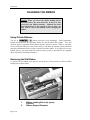
CHANGING THE PAPER
CHANGING THE RIBBON
Using Printek Ribbons
Removing the Old Ribbon
Installing the New Ribbon
3- 1
3- 1
3- 2
3- 3
3- 6
3- 6
3-10
3-13
3-16
3-16
3-16
3-17
CHAPTER 4 - USING SPECIAL FEATURES
UNLOADING AND SELECTING FORMS
HANDLING A PAPER ERROR CONDITION
Standard Paper Error Handling
Page Reprint
USING THE RIBBON CHECK FEATURE
Matching the Ribbon Wear Indicator to Printer Use
Turning Off Ribbon Checking
CHECKING SETUP CONFIGURATION
PRINTING SETUP INFORMATION
PARKING THE FORMSPRO 4503 TRACTORS FOR SHIPMENT
44444444444-
1
1
2
2
2
4
4
4
5
5
5
CHAPTER 5 - IN CASE OF DIFFICULTY
INTRODUCTION
SYMPTOMS AND POSSIBLE CAUSES
USING THE HEX DUMP MODE
SELECTING A QUALITY FORM
REPLACING THE AC POWER FUSE
555555-
1
1
1
4
5
5
APPENDIX A - ADVANCED CONTROL PANEL FEATURES
A- 1
Page iii
Table of Contents
SETUP: OPTIONS
SETUP: SECURITY
A- 1
A- 4
APPENDIX B - OPTIONAL RS-422 INTERFACE
B- 1
APPENDIX C - OPTIONAL COAXIAL/TWINAXIAL INTERFACE
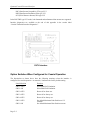
COAXIAL OPERATION
Option Switches When Configured for Coaxial Operation
TWINAXIAL OPERATION
Option Switches When Configured for Twinaxial Operation
Twinaxial Address Switch
Twinaxial Installation Preparation
Getting On-line
Twinaxial Verification Problems
COAXIAL/TWINAXIAL INTERFACE DIAGNOSTICS
CCCCCCCCCC-
APPENDIX D - OPTIONAL BUFFER EXPANSION
D- 1
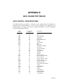
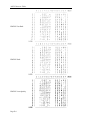
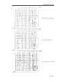
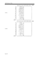
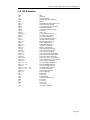
APPENDIX E - ASCII CHARACTER TABLES
ASCII CONTROL CODE DEFINITIONS
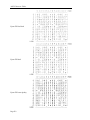
EPSON FX FONT SAMPLES
PC FONT SAMPLES
EBCDIC FONT SAMPLES
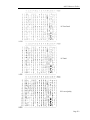
PC LATIN 2 (SLAVIC) FONT SAMPLES
OCR A FONT SAMPLE
OCR B FONT SAMPLE
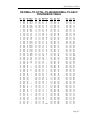
DECIMAL-TO-ASCII CONVERSION TABLE
EEEEEEEEE-
1
1
2
3
4
5
6
6
7
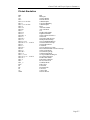
APPENDIX F - CONTROL CODE & ESCAPE SEQUENCE SUMMARIES
ANSI x3.64 EMULATION
EPSON FX EMULATION
IBM PROPRINTER EMULATION
LA-120 EMULATION
SIMPLE TTY EMULATION
PRINTEK EMULATION
FFFFFFF-
1
1
2
4
5
6
7
APPENDIX G - PRINTER RESET CONDITIONS
G- 1
APPENDIX H - CLONING PRINTER SETUP
CLONING FROM PRINTER TO PRINTER
Possible Cloning Errors
Information that is Cloned
USING A SETUP UNIT FOR CLONING
Cloning from a Printer to a Setup Unit
Cloning from a Setup Unit to a Printer
HHHHHHH-
1
1
2
4
5
5
6
6
8
8
1
1
2
2
3
3
4
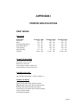
APPENDIX I - PRINTER SPECIFICATIONS
I- 1
APPENDIX J - SETUP MENU SUMMARIES
J- 1
GLOSSARY
Page iv
GLOSSARY- 1
INTRODUCTION
HOW TO USE THIS MANUAL
This manual provides information on how to install and operate your FormsPro 4000 series
printer. Below is a brief description of the information that is presented in each section. For
your convenience, a glossary of printer related terms is included at the back of this manual.
Introduction
Provides you with an introduction to the capabilities and
operation of the FormsPro 4300, FormsPro 4500 and the
FormsPro 4503 printers.
Installation and Quick Setup
Helps you select an appropriate location for the printer, and
then test and perform the initial setup of the unit.
Operation
Describes the control panel and ways to modify the
operating parameters which may be set for each of the ten
form setups and the host computer interface. Changing the
paper, using the three tractor paths in the FormsPro 4503,
and changing the ribbon are also described.
Using Special Features
Describes special messages which you may encounter when
you unload forms, how paper-error conditions are handled,
how ribbon usage is monitored, and how to use the Page
Reprint feature.
In Case of Difficulty
Describes what you should do in the event you encounter
difficulty using your printer, and provides you with a list of
possible causes for various symptoms and error messages.
Also included is information about where you can obtain
service, if it is required.
Following the above sections are appendices containing ASCII character tables and font
samples, additional control panel features, detailed interface specifications for the optional
interfaces, information on how to clone setup information from one printer to another, and
printer specifications.
Page 1-1
Introduction
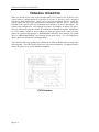
PRINTER MODEL DESCRIPTIONS
AND KEY FEATURES
The Printek FormsPro 4000 series printers are heavy duty serial dot matrix printers. The
FormsPro 4300 is a medium speed printer and the FormsPro 4500 and FormsPro 4503 are
high-speed printers. They have been specifically designed for printing on hard to print forms
which are often not printed adequately by other printers. Of course, the FormsPro 4000
series printers will also print on lighter forms.
All models provide straight paper paths for jam-free paper motion and a zero waste tear bar
for demand document applications.
You can permanently record up to ten complete sets of form parameters, which may then be
selected either at the printer's control panel or from the host computer. The FormsPro 4503
provides three sets of tractors, any of which may be selected in the form parameters for a
particular form. This allows the printer to automatically unload one form and load another
when it is selected either via the front panel buttons or a software command from the host
computer. When loading forms, the printer will automatically adjust the print head position
to match the thickness of the newly loaded form.
The printers come equipped with basic bar code capability, an industry standard parallel
interface and an RS-232C serial interface.
You can also order the printers with an optional RS-422 serial interface, or a
coaxial/twinaxial interface which emulates an IBM 3287 or 3262 printer, or an IBM 4214,
5225, or 5256 printer.
Other options include a 32K buffer, which increases the standard 4K character input buffer to
28K characters, the Imager and ImagerPlus bar code capabilities, and the FormsCutter which
may be used to cut each form as it is printed or to separate reports.
A specially designed print stand, which holds multiple paper supplies, is also available.
Page 1-2
INSTALLATION AND QUICK SETUP
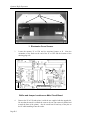
SELECTING AN APPROPRIATE INSTALLATION
LOCATION
The FormsPro 4000 series printers are designed to be installed on a Printek print stand, or on
an open-top print stand that allows paper to be fed through the paper supply slot on the
bottom of the printer. Since the printer also draws air through this slot for cooling, make sure
that no part of the print stand obstructs this slot. After cooling the electronics, the motors,
and the print head, the air is exhausted through the paper exit slot on top of the printer.
The installation location also requires power for the printer, support for cabling requirements
to your computer, and space for the paper supply(s) and printed paper collection.
After you unpack the printer as described in the unpacking instructions (make sure all
packing materials are removed as described) and place the printer at the desired location,
connect the power cord to the rear of the unit and plug the other end into a proper wall outlet.
Page 2-1
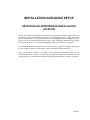
Installation and Quick Setup
3
1
2
1.
2.
3.
Page 2-2
Power Switch on Side of Printer.
Power Cord Connector.
Mounting Screws for Static Suppression Tinsel.
Installation and Quick Setup
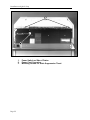
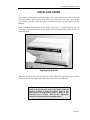
INSTALLING THE RIBBON
To install the ribbon, first lift the lid on the top of the printer; then lift the ribbon loading bail
as shown below.
1
2
1. Ribbon Loading Bail in up (open) position.
2. Ribbon Support Brackets.
Unpack the ribbon from its shipping container and remove the retainer from the slot on top of
the cartridge if present. Make sure the ribbon fabric is not twisted where it enters the
cartridge; then tighten the ribbon by turning the knob on top of the cartridge in the direction
indicated by the arrow on the cartridge.
Place the right end of the ribbon on the support bracket while you align the plastic tabs with
the slots in the bracket as shown on the next page. Then align and lower the left end of the
ribbon onto the left support bracket until it snaps into place. While doing so, the ribbon
fabric should lower into the area between the print head and the pins which support the metal
nose shield.
Page 2-3
Installation and Quick Setup
Ribbon Cartridge Installation.
Next lower the ribbon loading bail as shown below. This automatically places the ribbon
between the ribbon guides and the print head as the print head is placed back into the printing
position.
Lowering (closing) Ribbon Loading Bail.
Page 2-4
Installation and Quick Setup
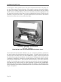
INSTALLING PAPER
If the printer is not currently turned on, push the ON-1 side of the power switch on the right
side of the printer. After you turn on the printer, it performs several self tests. If the printer
is a FormsPro 4503, these tests also make sure that the tractors are properly positioned after
shipment.
Paper is installed through the slot in the bottom of the printer. To open the unit so you can
install paper, pull outward on the bottom of the lower front panel of the printer as shown to
release the latch.
Opening Latch Panel.
While you pull outward on this panel, lift the front of the unit to expose the paper tractors.
The top of the unit will support itself in the up position while you load paper.
Caution: Do not open the unit in this fashion while the
printer is printing or forms are loaded. Doing so may
cause data to be printed incorrectly or paper to jam
when the cover is closed. Refer to the "Operation"
section for information about unloading forms.
Page 2-5
Installation and Quick Setup
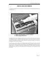
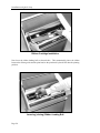
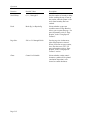
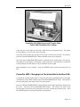
To load paper or forms, open the door on each tractor and position the holes in the paper over
the pins in the tractors; then close the doors. If the tractors are not set at the proper width for
the paper you are loading, simply move the lever beside the tractor door to the open position
and the tractor(s) will slide sideways. The tractors should be spaced far enough apart so that
the paper does not buckle in the center, but not so tight that the holes in the paper become
distorted by the pins in the tractors. A properly installed form is shown below. Note that the
form does not extend above the top of the tractor doors.
FormsPro 4503 With Form Installed
in Front Tractors.
Note that the forms do not extend above the tractor doors.
The FormsPro 4300 and FormsPro 4500 have only one set of tractors which are positioned in
the same location as the front tractors in the above picture. To install forms in the other sets
of tractors in the FormsPro 4503, press the FORM SELECT button on the front panel until
the desired form setup and tractor path is selected on the LCD display (this button's sequence
is 0 through 9, and back to 0, and may be operated while the case is either opened or closed).
Then press the LOAD button. This causes the selected tractors to move into position for
loading. Now load the paper or forms in the tractors as described in the previous paragraph.
Now close the case, select the form you desire (0 through 9), and press the LOAD button.
This places the form you have selected into position for printing. The following picture
shows a FormsPro 4503 with forms installed in all three sets of tractors and the center tractors
in place for operation.
Page 2-6
Installation and Quick Setup
FormsPro 4503 With Forms in All Tractor Paths.
Center Path Positioned for Loading.
Page 2-7
Installation and Quick Setup
TESTING THE PRINTER
When you turn the printer on, it automatically performs a series of self tests to assure that the
electronics and printer mechanisms are operational. In the FormsPro 4503, the shuttle
mechanism, which positions the tractors, also realigns itself if there is no paper installed or
the paper is not positioned above the tear bar.
If you wish to perform an actual printing test, perform the following steps to print a
barberpole test pattern:
1. Load plain paper that is eleven inches long. The pattern that is printed will be a
maximum of 80 columns wide.
2. Make sure that the printer is offline (the ONLINE indicator is not lit). If the printer is
on line, press the ONLINE button to turn the indicator off.
3. Press and hold the SETUP button until the second menu "Setup: INTERFACE" is
displayed; then release the SETUP button. Note that one beep will sound when the first
setup menu for forms is displayed, and two beeps will sound when the second menu for
interface is displayed.
4. Press the FUNCTION UP button until "Mode:" is displayed. The current emulation
mode will now be displayed. Remember which mode is currently displayed because
you will have to return to this value later for normal operation. If you wish, you can
record the mode here for future reference. Mode: ______________.
5. Press the VALUE UP button until "Mode: BarberPole" is displayed.
6. Press the SETUP button to exit setup mode. The printer will now reset and perform the
normal power-up diagnostics. Once these complete, the printer will begin to print the
barberpole pattern. To stop or resume printing the pattern, use the ONLINE button.
7. Once you have printed the pattern long enough to be sure the printer is operating
properly, press the ONLINE button to stop printing.
8. Press the FORM FEED button to advance the top of the next page to the tear bar and
tear off the printed page(s).
9. Return to the interface setup menu as described in step 3 above, and set the Mode value
back to its previous setting that you noted in step 4.
10. Press SETUP to exit setup mode. The printer will reset and return to normal operating
mode.
Page 2-8
Installation and Quick Setup
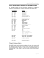
CONNECTING THE PRINTER TO A COMPUTER
The FormsPro 4000 series printers are supplied with an industry standard parallel interface
and an RS-232C interface as standard equipment. The printers are also available with an RS422 interface, or a coaxial/twinaxial interface.
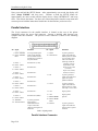
When the printer is shipped from the factory, the default configurations for these interfaces
are as shown below. If these are not appropriate for your installation, refer to the "Parallel
Interface" or "RS-232C Interface" sections which follow, or to one of the appendices if you
are using an optional interface.
Parallel and RS-232 Interface
Mode: Epson
I/O: Parallel
Data Bits: 8
RS-422 Interface
Mode: Epson
Baud Rate: 9600
Data Bits: 8
Parity: None
XON/XOFF: On
Coaxial/Twinaxial/Parallel and RS-232 Interface
Mode: Epson
I/O: CX/TX
Data Bits: 8
ENTERING THE INTERFACE MENU
AT THE CONTROL PANEL
In each of the following descriptions for connecting the printer to a computer, you may need
to access the printer's interface setup menu. The following paragraphs show you how to do
this.
After you connect the appropriate cable(s), as described in the section for the interface being
installed, turn the printer on.
If the printer is online (ONLINE indicator is on), press the ONLINE button on the front of the
printer to take the printer offline. This will cause the ONLINE indicator to turn off, and the
display will momentarily show an “OFFLINE” message to indicate that the printer is now
offline.
Page 2-9
Installation and Quick Setup
Next, press and hold the SETUP button. After approximately one second, the display will
show “Setup: FORMS” and beep once. Continue to hold the SETUP button for
approximately one more second until the display shows “Setup: INTERFACE” and beeps
twice. Then release the button. You have now entered the printer's interface setup menu and
can now proceed with the instructions listed below for the interface you desire to use.
Parallel Interface
The 36-pin connector for the parallel interface is located on the rear of the printer
immediately above the power cord connector. Connect a shielded cable between your
computer and this connector. The pin-out for this connecter is shown in the following
diagram.
Pin Signal
Definition
Pin Signal
Definition
____________________
1 DATA STROBE
19 DATA STROBE
RTN*
A host generated signal
which signals that data
lines are stable and that
the data may be stored in
the printer buffer.
2 DATA 1
20 DATA 1 RTN*
Host data bit 1 (LSB).
3 DATA 2
21 DATA 2 RTN*
Host data bit 2.
4 DATA 3
22 DATA 3 RTN*
Host data bit 3.
5 DATA 4
23 DATA 4 RTN*
Host data bit 4.
6 DATA 5
24 DATA 5 RTN*
Host data bit 5.
7 DATA 6
25 DATA 6 RTN*
Host data bit 6.
8 DATA 7
26 DATA 7 RTN*
Host data bit 7.
9 DATA 8
27 DATA 8 RTN*
Host data bit 8 (MSB).
____________
10 ACKNLG
28 ACKNLG RTN*
A printer generated
signal which is
transmitted after the
receipt of each data
character and negation of
the BUSY.
11 BUSY
29 BUSY RTN*
A printer generated
signal which indicates
that the printer is unable
to receive data. Busy
will be set under the
following conditions:
Character received.
Input buffer is full.
Printer is not on line
(see SLCT).
Paper error (see PE).
Fault (see FAULT).
12 PE
A printer generated
signal which indicates a
paper out or paper
jammed condition.
13 SLCT
A printer generated
signal which indicates
that the printer is on line
and ready to receive data.
14 ±0V
Signal ground.
16 ±0V
Signal ground.
___________________
31 INPUT PRIME
30 INPUT PRIME
RTN*
_________
32 FAULT
*RTN = Signal ground.
Parallel Interface Connector.
Page 2-10
Ignored.
A printer generated
signal which indicates
that the printer requires
attention.
Installation and Quick Setup
Enter the interface menu as described above. Then press the FUNCTION UP button to
display the “I/O:” function. Now press the VALUE UP button until “Parallel” is displayed
(or CX/TX if that option is installed). Now press the FUNCTION UP button again to display
the “Data Bits:” function. Use the VALUE UP button to select either 7 or 8 data bits as
required by your computer and/or software. This will normally be set to 8.
Finally, press the SETUP button to exit the setup mode and reset the printer. The printer is
now ready to receive parallel data.
RS-232C Serial Interface
A 25-pin female “D” type connector is located on the rear of the printer immediately to the
right of the 36-pin parallel connector (or above it if the coaxial/twinaxial interface is
installed). Connect a shielded cable between your computer and this connector. The pin-out
for this connector is shown below.
Pin
1
2
3
4
5
6
7
8
11
20
Signal
Chassis ground.
Transmit data. (Printer output).
Receive data. (Printer input).
Request to send (set). (Printer output).
Clear to send (ignored). (Printer input).
Data set ready (ignored). (Printer input).
Signal ground.
Carrier detect (ignored). (Printer input).
Printer busy. (Printer output).
Data terminal ready. (Printer output).
RS-232C Serial Interface Connector.
To configure the printer for serial data, more information is required than for some of the
other interfaces. In particular, you must know the baud rate, number of data bits, type of
parity checking, and flow control method required by your computer. Check your computer
manual or contact your computer dealer for this information.
Enter the interface menu as described above. Then press the FUNCTION UP button to
display the “I/O:” function. Now press the VALUE UP button until “Serial” is displayed.
Before proceeding, the factory default values for the RS-232C serial configuration are 9600
baud, 8-data bits, no parity, busy-polarity low, and XON/XOFF and ETX/ACK handshakes
off. If your computer requires you to change any of these parameters, please refer to
“Entering the Interface Setup Menu” in the Operation section of this manual. Otherwise,
simply press SETUP again to exit the setup mode and reset the printer. The serial interface
with the above parameters is now active.
Page 2-11
Installation and Quick Setup
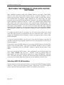
MATCHING THE PRINTER TO YOUR APPLICATION
SOFTWARE
Many application programs output only printable characters and simple control codes.
However, some require special printer features and use a particular “language” or set of
control codes and escape sequences to direct the printer to enable or disable these features.
The FormsPro 4000 series printers supply emulations for the control codes and escape
sequences used by the ANSI X3.64 specification, Epson FX series printers, IBM Proprinter,
Digital Equipment Corporation's LA-120, a simple TTY emulation mode (which ignores
most control codes and escape sequences), and a special Printek emulation mode. The
Printek emulation may be used at any time to control features which are not supported by the
other printers being emulated. To review the list of control codes and escape sequences
supported by these emulations, refer to the appropriate section in the Programmer's Manual.
The Programmer’s Manual may be obtained by returning the request form packed with the
printer.
To complete the initial setup of your printer, you will need to know which set of control
codes and escape sequences your applications will use to control the printer. Refer to your
computer and application software manuals or contact your computer and/or software dealer
for this information.
To select the desired emulation, you will need to first enter the interface setup menu as
described in the following paragraphs, and then proceed to the appropriate section below to
select the emulation.
If the printer is online (ONLINE indicator is on), press the ONLINE button on the front of the
printer to take the printer offline. This causes the ONLINE indicator to turn off, and the
display to momentarily show an “OFFLINE” message to indicate that the printer is now
offline.
Next, press and hold the SETUP button. After approximately one second, the display will
show “Setup: FORMS” and beep once. Continue to hold the SETUP button for
approximately one more second until the display shows “Setup: INTERFACE” and beeps
twice. Then release the button. You have now entered the printer's interface setup menu and
can now proceed with the instructions listed below for the emulation you desire to use.
Selecting ANSI X3.64 Emulation
Enter the interface menu as previously described. Press the FUNCTION UP button to display
“Mode: n”. Then use the VALUE buttons to select “ANSI X3.64”. Press SETUP again to
exit the setup mode and reset the printer. ANSI X3.64 emulation is now selected.
Page 2-12
Installation and Quick Setup
Selecting Epson Emulation
Enter the interface menu as previously described. Press the FUNCTION UP button to display
“Mode: n”. Then use the VALUE buttons to select “Epson”. Press SETUP again to exit the
setup mode and reset the printer. Epson emulation is now selected.
Selecting Proprinter Emulation
Enter the interface menu as previously described. Press the FUNCTION UP button to display
“Mode: n”. Then use the VALUE buttons to select “Proprinter”. Press SETUP again to exit
the setup mode and reset the printer. Proprinter emulation is now selected.
Selecting DEC LA 120-RA Emulation
Enter the interface menu as previously described. Press the FUNCTION UP button to display
“Mode: n”. Then use the VALUE buttons to select “LA-120”. Press SETUP again to exit the
setup mode and reset the printer. LA-120 emulation is now selected.
Selecting TTY Emulation
Enter the interface menu as previously described. Press the FUNCTION UP button to display
“Mode: n”. Then use the VALUE buttons to select “TTY”. Press SETUP again to exit the
setup mode and reset the printer. TTY emulation is now selected.
Selecting Printek Emulation
Enter the interface menu as previously described. Press the FUNCTION UP button to display
“Mode: n”. Then use the VALUE buttons to select “Printek”. Press SETUP again to exit the
setup mode and reset the printer. Printek emulation is now selected.
Page 2-13
OPERATION
INTRODUCTION
This section assumes that your printer has already been installed according to the information
in “Installation and Quick Setup”, and describes the daily operation of the FormsPro 4000
series printers. In particular, using the control panel, changing paper or forms, and changing
the ribbon cartridge are discussed.
CONTROL PANEL OPERATION AND SETUP MENUS
The FormsPro 4000 series printers feature an intuitive, easy-to-use control panel which
provides immediate access to the controls required by most operators. Individual indicators
are available which provide a quick indication of printer status, as well as a 16-character
display which provides even more status information.
Many more features, including form and interface parameters, are available through the
SETUP mode. All features which are modified during setup are stored in nonvolatile
memory and are used each time the printer is turned on or reset. For more information, refer
to the appendix on “Printer Reset Conditions”.
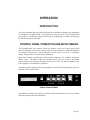
The printer's control panel consists of six pushbutton switches, four LED indicators, and a 16character LCD as shown below.
Printer Control Panel.
The pushbutton switches (or buttons), the LCD, and the LED indicators provide you with the
following controls and status information:
Page 3-1
Operation
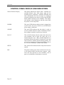
CONTROL PANEL DISPLAY AND INDICATORS
Sixteen Character Display
This display indicates the printer status. Normally, the
currently-selected form (and tractor path on the
FormsPro 4503) is displayed. ONLINE, OFFLINE, and
other informational and error messages are displayed
when the conditions occur and/or you press the ONLINE
button without clearing an error condition. This display
also indicates various parameters and their values when
the printer is in the setup mode.
POWER
This green LED indicates that the printer is plugged into
a power source, the power switch is on, and the internal
power supply is functional.
ONLINE
This green LED indicates that the printer is ready to
receive printable characters and/or commands from the
host computer, and print or perform as requested.
FAULT
This red LED indicates that the printer has detected an
error condition, such as paper out, paper jam, or an
internal diagnostic error. Many internal diagnostics are
performed each time the printer is turned on or reset, and
some continue to monitor operation during printing. For
a list of error messages and suggested remedies, refer to
the “In Case of Difficulty” section of this manual.
SETUP
This yellow LED indicates that the setup mode has been
entered.
Bell
The printer sounds a tone when it is directed to do so by
a bell character (BEL) from the host computer. Other
tones also alert operators of error conditions, such as
paper out, and indicate when buttons are pressed.
Page 3-2
Operation
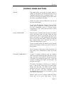
CONTROL PANEL BUTTONS
ONLINE
This button allows you to place the printer online or
offline, as indicated by the ONLINE indicator, and as
temporarily displayed on the 16-character display. It is
also used for starting and stopping the test pattern while
the printer is in the Barber Pole mode.
NOTE: The printer must be offline before you can use
any of the other buttons.
If you press and hold this button at power-up/reset,
internal printer information is displayed on the LCD.
For more information, refer to “Checking Printer
Configuration” in the “Using Special Features” section
of this manual.
LOAD / FORM FEED
When no paper is currently loaded (a paper out condition
exists), this button loads the paper which has been
installed in the tractors by moving the top edge of the
paper to the tear bar. In the FormsPro 4503, this button
may also cause the tractor path to change if a form has
been selected which uses a different path (refer to
UNLOAD/FORM SELECT below).
If paper is already loaded, this button uses the currently
selected form length to advance the paper to the top of
the next form.
For a description of this button while the printer is in
setup mode, refer to “Introduction to Setup” later in this
chapter.
UNLOAD / FORM SELECT
If paper is currently loaded (no paper out condition
exists), this button unloads the paper and places the top
edge of the paper in the tractors in the base of the unit.
This allows you to change the paper easily. A paper out
condition is displayed to indicate that the paper was
unloaded successfully.
The printer will attempt to unload up to 36 inches of
paper. If the top edge of the paper is not found, paper
motion will stop and “Too Much Paper” will be
displayed on the LCD. Normally, previous pages should
be torn off before you press UNLOAD.
It is
recommended that you not use this method to unload
more than the current form.
When no paper or form is currently loaded, this button
selects one of ten preset form setups.
In the
Page 3-3
Operation
FormsPro 4503, this may also select a different set of
tractors to be used the next time you press the LOAD
button.
The printer will not allow you to change the form during
printing. If you press the FORM SELECT button while
there is still a line to print, the button press is rejected,
the bell sounds, and the message “Finish Printing!”
flashes on the LCD. If this happens, you should place
the printer back on-line, allow the form to finish
printing, and then place the printer off-line and select the
desired new form. For more information, refer to
“Finish Printing!” in the “Using Special Features”
section.
If you press and hold this button at power-up/reset on
the FormsPro 4503, and paper has not been loaded, the
tractor shuttle moves all the way forward to its parked
position. NOTE: The tractor shuttle should always be
parked whenever the printer is being transported.
For a description of this button while the printer is in the
setup mode, refer to “Introduction to Setup” later in this
chapter.
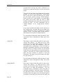
ALIGN UP
This button is used to adjust the paper in respect to the
current form position. To adjust the top of form
position, you must insure that the printer is at the top of
form before you make this adjustment. You can
accomplish this by performing a Form Feed prior to
making the adjustment. Each time you press this button,
the paper moves up 1/72nd of an inch. If you hold this
button down, the paper advances the amount required to
complete a line feed (LF) at the currently selected line
pitch, and then continues to advance in full line
increments. The longer you hold this button, the faster
the paper will move.
For a description of this button while the printer is in the
setup mode, refer to “Introduction to Setup” later in this
chapter.
ALIGN DOWN
Page 3-4
This button is used to adjust the paper in respect to the
current form position. To adjust the top of form
position, you must insure that the printer is at the top of
form before you make this adjustment. You can
accomplish this by performing a Form Feed prior to
making the adjustment. Each time you press this button,
the paper moves down 1/72nd of an inch. If you hold
this button down, the paper moves the amount required
to complete a line feed (LF) at the current line pitch, and
Operation
then continues to move in full line increments. The
longer you hold this button, the faster the paper will
move.
For a description of this button while the printer is in the
setup mode, refer to “Introduction to Setup” later in this
chapter.
SETUP
This button enters and exits the setup menus that are
used to set parameters for up to ten unique form
configurations, and for setting the parameters required
for the printer to communicate successfully with your
computer. This button and a detailed description of the
features of the setup mode are described in “Introduction
to Setup” which follows.
If you press and hold this button at powerup/reset, the
current setup configuration may be printed. Refer to
“Printing Setup” in the “Using Special Features” section
of this manual.
Page 3-5
Operation
INTRODUCTION TO SETUP
The setup mode allows you to easily set form parameters for each of the ten form
configurations, and to set interface hardware and emulation parameters. To make it easier,
the menus and their functions are accessed in the order in which they are most often used.
You can access the setup menus by pressing and holding the SETUP button until the desired
menu is displayed on the LCD. When setup has been entered, the yellow SETUP indicator
lights. At this time, the buttons that have yellow labels below them perform as indicated by
those labels. To exit the setup mode, press the SETUP button.
While the printer is in a menu, you can use the FUNCTION UP and FUNCTION DOWN
buttons to select any function. Whenever you select a function, its current value is displayed.
To change the value or setting of a function, use the VALUE UP and VALUE DOWN
buttons. The function values that are entered in all menus are on a “what you see is what you
get” basis. Whatever value you leave displayed for any function will become the default
value until you change it again. All parameter values are saved in a nonvolatile memory that
is used during initialization the next time the printer is turned on or reset. The printer
automatically performs a reset when it exits the setup menus so that values just set can be
adopted immediately. Refer to appendix on “Printer Reset Conditions” for other values that
may be affected.
The next two sections describe the Forms Menu and the Interface Menu. For more advanced
features, Refer to the appendix on “Advanced Control Panel Features”.
ENTERING THE FORMS SETUP MENU
To change parameters for the currently selected form, first take the printer offline. Next,
press and hold the setup button until “Setup: FORMS” is displayed (approximately one
second) and the bell beeps one time to indicate the first setup menu has been reached. At this
time, you are able to view and/or edit the various function values for the currently selected
form.
The function values which may be modified and their respective value ranges for any of the
ten form selections are listed below. Although you can use the FUNCTION UP or
FUNCTION DOWN buttons to select functions, they are listed here in the order of function
up. The first function is “Form #:” which will display the form to be modified as you access
the other functions. This will initially display the form number that was selected when you
first entered setup (see the description of the UNLOAD/FORM SELECT button earlier in this
chapter). You may use the VALUE UP or VALUE DOWN buttons to select a different form
to modify. However, the form that was selected when you entered setup will still be selected
when you exit setup.
In the descriptions below, “F#” refers to “F0” through “F9” to indicate the number of the
form currently accessed. The factory default settings are indicated by an asterisk (*) where
applicable.
Page 3-6
Operation
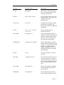
Function
Possible Values
Description
Form #:
0 through 9
Allows you to select the desired
form. The printer defaults to the
currently selected form.
F# Path:
Front, Center, or Rear
Sets the tractor path to be used for
the current form. This function is
available only on the
FormsPro 4503.
F# Auto Cut:
Yes or No*
Available only when the optional
FormsCutter is installed. See
FormsCutter manual for additional
information.
F# CPI:
10*, 12, 13.3, 15, 16.74,
17.14, or 20
Sets the character pitch in
Characters Per Inch.
F# Left Mar:
0* through 134
Sets the left margin in columns
(characters) from the leftmost print
position. Column width is based
upon CPI. The left margin must
be less than the right margin.
F# Right Mar:
1 through 255, or MAX*.
Sets the right margin in columns
(characters) from the leftmost print
position. A value of MAX sets the
margin to the rightmost print
position, regardless of CPI. The
right margin must be greater than
the left margin.
F# LPI:
6* or 8
Sets the line pitch to 6 or 8 lines
per inch.
F# Length:
1 through 227 (66*)
Sets the form length in lines at the
current line pitch. For example:
for an eleven inch form, enter 66 if
you are using six lines per inch or
88 if you are using eight lines per
inch.
F# Top Mar:
0* through 255
Sets the top margin by adding the
specified number of lines to the
top of the form.
F# Btm Mar:
0* through 255
Sets the bottom margin in lines
lines from the bottom of the form.
Page 3-7
Operation
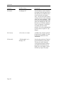
Function
Possible Values
Description
F# Scroll+:
0* through 127
Sets the distance in lines from the
top margin to the first print line of
the form (does not add these lines
to the form as the top margin
does). Scroll can be used to allow
existing software to take advantage
of the zero-waste capability. If the
first line is printed too high on the
paper after aligning the edge with
the tear bar, use Scroll to position
it lower on the page. Scroll does
not modify the top of form
position. It is not recommended to
use this with, or in place of, Top
Margin.
F# Cut Adj:
-85 to +84, 0*, or Auto
Available only when the optional
FormsCutter is installed. See the
FormsCutter manual for more
information.
F# Prnt Adj:
-128 through 0*, or 0
through +127
Sets the print position in 72nds of
an inch from the top of the form.
This may be used to align the
vertical print position to match a
preprinted form which does not
begin at an even number of lines
from the top edge of the paper.
Page 3-8
Operation
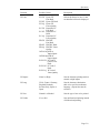
Function
Possible Values
Description
F# Font:
FX FD
Epson FX
Fast Draft
FX DF Epson FX Draft
FX LQ Epson FX
Letter Quality
PC FD Proprinter PC
Fast Draft
PC DF Proprinter PC
Draft
PC LQ Proprinter PC
Letter Quality
EB FD EBCDIC
Fast Draft
EB DF EBCDIC Draft
EB LQ EBCDIC Letter
Quality
OCRA OQ OCR-A
Optical Qual
OCRB OQ OCR-B
Optical Qual
PCL2 FD PC Latin 2
(Slavic) Fast
Draft
PCL2 DF PC Latin 2
Draft
PCL2 LQ PC Latin 2
Letter Quality
Selects the font to be used. Fonts
not installed will not be displayed.
F# Impact:
Norm* or High
Sets the character printing mode to
normal or high impact.
F# Lang:
USA*, France, Germany,
England, Denmark,
Sweden, Italy, Spain, or
Japan
Sets the character substitution
table to be used for an alternate
language. (Epson font must be
selected).
F# Zero:
Normal* or Slashed
Sets the type of zero to be printed.
F# Unidir:
Yes or No*
Sets unidirectional printing instead
of bidirectional printing.
Page 3-9
Operation
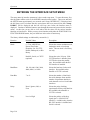
ENTERING THE INTERFACE SETUP MENU
The setup menu for interface parameters is the second setup menu. To enter this menu, first
take the printer offline (refer to the ONLINE button described earlier). Then press and hold
the SETUP button approximately two seconds until “Setup: INTERFACE” is displayed and
the bell beeps twice to indicate that the second menu has been entered (Note that “Setup:
FORMS” will be displayed and the bell will beep once before the interface menu is
displayed. Continue to hold the button to pass through this menu and proceed to the interface
menu). At this time you are able to view and/or edit the values for the various interface
functions as listed below. While you may select functions with either the FUNCTION UP or
FUNCTION DOWN buttons, they are listed here in the order of function up.
The factory default settings are indicated by an asterisk (*).
Function
Possible Values
Description
Mode:
n = Test, ANSI X3.64,
Epson*, Bar Codes,
Proprinter, LA-120, TTY,
Printek, Barberpole, or Hex
Dump
Selects the current emulation mode,
barberpole mode, or hex dump
mode. The test mode is for factory
use only.
I/O:
Parallel*, Serial, or CX/TX
(optional)
Selects the active I/O port. If the
CX/TX interface is installed, then
CX/TX also selects the parallel
port. Not available when the RS422 interface is installed.
Baud Rate:
150, 300, 600, 1200, 2400,
4800, 9600*, or 19200
Selects the baud rate for the serial
interface. Not available when
Parallel or CX/TX is selected.
Data Bits:
7 or 8*
Selects the number of data bits in
the serial character frame and the
number of significant data bits in
each character received via all other
interfaces.
Parity:
None*, Ignore, Odd, or
Even
Selects the parity checking
requirements for the serial data bits.
Not available when Parallel or
CX/TX is selected.
Busy:
Low* or High
Selects the polarity of the busy
signal (pin 11 of the RS-232C
interface). Available only when the
RS-232C interface is installed and
Serial is selected.
Page 3-10
Operation
Function
Possible Values
Description
DTR:
Power*, Online, or Busy
Selects the condition to be reflected
by the DTR signal (pin 20 of the
RS-232C interface). Available
only when the RS-232C interface is
installed and Serial is selected.
XON/XOFF:
Off* or On
Enables or disables the
transmission of the XON and
XOFF characters from the printer
to the host to control data flow to
the printer. Not available when
Parallel, or CX/TX is selected.
ETX/ACK:
Off* or On
Enables or disables the ACK
response to receipt of the ETX
character. Not available when
Parallel, or CX/TX is selected.
Auto CR:
Off* or On
Enables or disables automatic
Carriage Returns (CR) when a Line
Feed (LF), Vertical Tab (VT), or
Form Feed (FF) is received.
Auto LF:
Off* or On
Enables or disables automatic Line
Feeds (LF) when a Carriage Return
(CR) is received.
Long Line:
Wrap* or Trunc
Sets whether characters beyond the
right margin will be wrapped to the
next line or truncated.
Left Edge:
Fixed or Float*
Sets whether the left edge of the
line will be printed 1/2 inch from
the detected edge of the paper or be
fixed at position “0” on the ruler.
FF at TOF:
Yes* or No
Sets whether Form Feeds (FF) will
be performed when received from
the host computer if the paper is
already positioned at the top of
form (TOF).
Page 3-11
Operation
Function
Possible Values
Description
Scroll Delay:
0, 1*, 2 through 15
Sets the number of seconds to delay
before scrolling the top of form to
the tear bar when the printer is idle
and a form boundary has been
reached.
Fault:
Break Pg*, or Reprint Pg
Selects whether a paper-out
condition causes a Page Break or
allows you to reprint the page. For
more information, refer to “Page
Reprint” in the “Using Special
Features”.
Page Size:
256* or 512 through 28160
Sets the page size in characters,
when Page Reprint is selected.
When you do not use page reprint,
leave the value set to 256. For
more information, refer to “Page
Reprint” in the “Using Special
Features” section.
Chars:
Control* or Printable
Selects whether certain control
character symbols will be printed
(emulation dependent), or be
treated as control characters.
Page 3-12
Operation
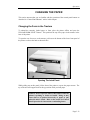
CHANGING THE PAPER
This section assumes that you are familiar with the operation of the control panel buttons as
described in “Control Panel Buttons” earlier in this chapter.
Changing the Form in the Tractors
To unload the currently loaded paper or form, place the printer offline and press the
UNLOAD/FORM SELECT button. This positions the top of the paper in the tractors in the
base of the printer.
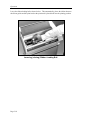
To open the case for access to the tractors, pull out on the bottom of the lower front panel of
the printer to release the latch as shown below:
Opening The Latch Panel.
While pulling out on this panel, lift the front of the printer to expose the paper tractors. The
top of the unit will support itself in the up position while you load paper.
Caution: Do not open the unit in this fashion while the
printer is printing or forms are loaded. Doing so may
cause data to be printed incorrectly or paper to jam
when the unit is closed. Refer to the section on Control
Panel Operation for instructions on unloading forms.
Page 3-13
Operation
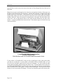
Open the doors on the tractors and remove the paper or form through the slot in the base of
the printer.
Bring the new paper up through the slot in the base and position the holes of the paper over
the pins in the tractors; then close the doors. Position the left tractor as shown on the label
located in the base of the printer. If the tractors are not set at the proper width for the paper
being loaded, simply move the lever beside the tractor door to the open position and slide the
tractor(s) sideways. Space the tractors far enough apart so the paper does not buckle in the
center, but is not so tight that the holes in the paper become distorted by the pins in the
tractors. A properly installed form is shown below. Note that the paper is not above the tops
of the tractor doors.
FormsPro 4503 With Forms Installed
in Front Tractor Path.
Note that the forms do not extend above the tractor doors.
If your printer is a FormsPro 4503, and you wish to install paper in the other tractor paths,
you may do so at this time. If your printer is a FormsPro 4300 or FormsPro 4500, or if you
do not wish to load other paths, proceed to the next paragraph. You can position the other
tractor paths for loading without closing the printer's case. To load another tractor path, press
the UNLOAD/FORM SELECT button on the front panel until the desired form and tractor
path is indicated on the LCD display. Then press the LOAD button. This causes the selected
tractors to move into position for loading. You may now install the paper in this tractor path.
Page 3-14
Operation
FormsPro 4503 With Forms in All Tractor Paths.
Center Path Positioned for Loading.
Close the case of the printer by lowering it until the lower front panel closes. The printer
LCD will display “Case Closed” when you do this.
Check the LCD to make sure the correct form setup (0-9) has been selected. If necessary,
press the UNLOAD/FORM SELECT button until the correct one is displayed.
Now press the LOAD/FORM FEED button to position the top of the paper at the tear bar.
The printer LCD will display “Load Paper” when you do this. After the paper is loaded, the
LCD will display the form number, and if a FormsPro 4503, the path.
Paper installation is now complete. Press the ONLINE button to place the printer back online.
FormsPro 4503: Changing to a Form Installed in Another Path
To unload the currently loaded paper or form, first tear off any forms that have been printed.
Then take the printer offline and press the UNLOAD/FORM SELECT button. This positions
the top of the paper in the tractors in the base of the printer.
Press the UNLOAD/FORM SELECT button until the desired form and path are displayed on
the LCD. Then press the LOAD/FORM FEED button. The tractors will move to the
specified path (if necessary) and position the top of the selected form at the tear bar. Press
the ONLINE button to place the printer back into operation.
Page 3-15
Operation
CHANGING THE RIBBON
Caution: When you access the ribbon loading bail as
described below, the print head may be hot if a long
report has just finished printing. Although the print
head should never be hot enough to cause a burn, you
may wish to wait several minutes before changing the
ribbon.
Using Printek Ribbons
The use of
ribbons provides several advantages. Most importantly,
Printek ribbons provide the maximum ribbon life and print head life possible. They also
allow the printer's automatic ribbon change indicator system to operate. While it is possible
to use non-Printek ribbons in your printer, doing so will limit the warranty on the print head
and other mechanisms which are used to advance the ribbon fabric. If you choose to use nonPrintek ribbons, you must disable the ribbon sensing system as described in the appendix
titled “Advanced Control Panel Features”.
Removing the Old Ribbon
To remove the old ribbon, first open the lid on the top of the printer and lift the ribbon
loading bail as shown below.
1
2
1.
2.
Page 3-16
Ribbon Loading Bail in Up (open)
Position.
Ribbon Support Brackets.
Operation
Remove the old ribbon by lifting the left hand end of the ribbon off of the left support
bracket. Then lift out the other end of the ribbon and set the ribbon aside. If the printer
power is on, “Ribbon Removed” will be displayed as the ribbon is lifted out.
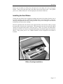
Installing the New Ribbon
Unpack the new ribbon from its shipping container and remove the retainer from the slot on
top of the cartridge if present. Make sure the ribbon fabric is not twisted where it enters the
cartridge; then tighten the ribbon by turning the knob on top of the cartridge in the direction
indicated by the arrow on the cartridge.
Place the right hand end of the ribbon on the support bracket as shown below while you align
the plastic tabs with the slots in the bracket. Then align and lower the left end of the ribbon
onto the left support bracket until it snaps into place. When you do this, the ribbon fabric
should lower into the area between the print head and the pins which support the metal nose
shield. If the printer power is on, “Ribbon Installed” will be displayed as the ribbon is
installed.
Ribbon Cartridge Installation.
Page 3-17
Operation
Lower the ribbon loading bail as shown below. This automatically places the ribbon between
the ribbon guides and the print head as the print head is placed back into the printing position.
Lowering (closing) Ribbon Loading Bail.
Page 3-18
USING SPECIAL FEATURES
This section describes some of the features which are unique to FormsPro 4000 series
printers. These features include instructional messages, which you may encounter when you
change forms, options available for handling a paper out condition, and how to set the ribbon
wear indicator to match how you use your printer. Also included are instructions for
checking the printer configuration and for printing a list of setup information, including all of
the form setup parameters.
UNLOADING AND SELECTING FORMS
When unloading forms, the printer may display the message “Too Much Paper”, “Tear Off
Paper”, or “Finish Printing!”. The cause and remedy for each message is described below.
“Too Much Paper”
This message is displayed when the UNLOAD button has been pressed and the printer senses
that there is too much paper to unload reliably. The solution is to simply press FORM FEED
to place the top of the next form at the tear bar for easy tearing, tear off any remaining
form(s), and then proceed with the unload operation. Note that the printer unload up to 36
inches of paper before displaying the error message, so it may be desirable to press FORM
FEED enough times to ensure that there are no partially printed forms left in the printer.
“Tear Off Paper”
This message is displayed when an escape sequence is used to select a new form and the
printer senses that there was a form already past the tear bar. When this occurs, the paper
will automatically be placed back to the position it was at before the escape sequence was
processed. To clear this condition, tear off the form(s) (you may need to press FORM FEED,
if the previous form was not completed) and place the printer back online. For more
information about loading different forms with escape sequences, refer to the FormsPro 4000
Series Programmer's Manual. The Programmer’s Manual may be obtained by returning the
form packed with the printer.
“Finish Printing!”
This message is displayed when a form has been unloaded, the FORM SELECT button has
been pressed and there is a partial line in the print buffer which may belong on the actual
form that is being unloaded. This condition may occur if the host computer has sent part of a
line, but has not terminated it with a Carriage Return, Line Feed, etc. To allow the printer to
finish this line and/or form, simply press LOAD to reload the form and press ONLINE to
allow the printer to complete the form.
Page 4-1
Using Special Features
If you do not wish to finish printing this line/form, you may force the printer to delete this
partial line from its buffer by pressing and holding the UNLOAD/FORM SELECT button
through the following series of messages. When the printer displays “Finish Printing!”,
continue to hold the button. After two seconds the printer will display “Cancel Printing?”.
Continue to hold the button for two more seconds and the printer will display “Print
Canceled”. Now release the button and you may change the paper, or you may press the
FORM SELECT button to select another form.
HANDLING A PAPER ERROR CONDITION
Paper errors may be caused by either a paper out or a paper jam. The printer will deal with a
paper error condition in one of two ways. The factory default method is described below
under “Standard Paper Out Handling”. For a description of how paper errors are handled
when Page Reprint is enabled, refer to “Handling Paper Errors With Page Reprint Enabled”
in the “ Page Reprint” section that follows.
Standard Paper Error Handling
The standard way of dealing with a paper error is that printing will stop and the printer will
go off line as soon as a paper error condition is detected. In the case of paper out, the paper
will be ejected from the tractors. Printing will continue at the top of the next form when it is
loaded.
PAGE REPRINT
Page Reprint is a feature which may be used to reprint a page in its entirety after a paper error
occurs, rather than just resuming printing as described above. This may be used when you
are printing on preprinted forms to prevent splitting one form's data onto two separate pages.
Please read through all of the following topics concerning Page Reprint to make sure you
wish to use it before you enable it.
Enabling Page Reprint
To enable page reprint, first take the printer off-line. Press and hold the SETUP button until
“Setup: INTERFACE” is displayed. Then press the FUNCTION UP button until “Fault:” is
displayed. Now press a VALUE button to select “Reprint Pg”. You must now set the page
size as described below.
Setting the Reprint Page Size
Page 4-2
Using Special Features
After you select reprint page, press the FUNCTION UP button to display “Page Size:”.
Before you use the VALUE buttons to select the page size, please read the following
discussion, which describes the available values.
Page size is set in increments of 256 characters. Ideally, the specified page size should be as
large as the largest page to be printed on any form. This includes non-printing characters
such as spaces, tabs, carriage returns, and line feeds. If the page size is not set large enough,
it will not be possible to reprint the page. If the size is large enough, the message “Reprinting
Page!” will be displayed after paper is loaded and the printer is placed back on-line. If the
size is not large enough, the printer will display “Cannot Reprint!” and will continue printing
just as though the reprint option is not enabled.
The buffer space for the page reprint is taken from the I/O buffer, so do not set the page size
unnecessarily large. The standard buffer size is 4096 characters. A buffer expansion option
is available which will increase the I/O buffer to a total of 28672 characters. At least 512
characters must be left allocated to the I/O buffer when you set the page size. Maximum page
sizes are 3584 characters and 28160 characters. The buffer expansion option is
recommended if page reprint is to be used, since it will allow a larger page size and still retain
a reasonable I/O buffer size.
Handling Paper Errors With Page Reprint Enabled
When a paper error occurs during printing, just load more paper and place the printer back on
line. The printer will sound the bell and display “Reprinting Page!”. Place the printer back
on-line and the printer will print the current form in its entirety and continue printing
subsequent pages.
Another feature of Page Reprint is the ability to save a form if printing begins and the wrong
form was accidentally selected. If this occurs, quickly take the printer off-line before the first
page finishes printing. Do not press FORM FEED. Pressing FORM FEED will cause the
current page to be “completed”, which will remove it from the reprint buffer and cause that
much of the form to be lost. Instead, unload the form and load the correct form. The bell will
beep and “Reprinting Page!” will be displayed. Place the printer on-line to reprint the first
page and continue printing subsequent pages.
Using Escape Sequences With Page Reprint Enabled
To reprint a page, the printer performs a carriage return at the top of the newly loaded form,
and then reprocesses all data received for the incomplete page. If escape sequences have
been used in the partially printed page, the printer may be left in a different state than when
the page began printing originally.
Escape sequences may be used successfully with page reprint, if you are careful. At the
beginning of each page, escape sequences should be sent to reset any default attributes that
may have changed. This will insure that reprinted pages look the same as they would have on
the first printing. For example, assume that the printer is set for normal print. Part way
through the page, an escape sequence is used to select bold print. If it is necessary to reprint
the page at this point, the beginning of the page will be reprinted in bold because bold was
never turned off. The problem may be avoided by sending an escape sequence to turn bold
off at the beginning of the page (even though it is already off under normal circumstances).
Page 4-3
Using Special Features
For more information on using escape sequences, refer to the FormsPro 4000 Series
Programmer's Manual.
USING THE RIBBON CHECK FEATURE
The use of
brand ribbons (Printek part number 90481) provides a number
of benefits in the use of your FormsPro 4000 series printers. First of all Printek ribbons offer
a 23,000,000 draft character life, substantially more than that of most imitations. The
specially formulated ink also provides the best lubrication for the print head and thus the
longest print head life. Be sure to insist on genuine Printek ribbons.
Using Printek brand ribbons also allows the printer’s ribbon checking feature to operate. The
ribbon checking feature will insure that your printer does not try to print when there is no
ribbon installed which could result in the loss of valuable data.
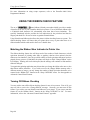
Matching the Ribbon Wear Indicator to Printer Use
The ribbon checking feature also will keep track of the number of draft characters (or draft
equivalent characters if printing other fonts or graphics) that have been printed since the
ribbon was last installed. Once the specified number of draft equivalent characters has been
printed (factory preset to 23,000,000), the printer will begin to flash “Change Ribbon” on the
LCD display. Printing will not be interrupted, but the message will continue to flash until the
ribbon is changed.
Your particular printing application may dictate that you change the ribbon after more or less
than fifteen million characters. If you wish to receive the Change Ribbon message after a
different amount of usage, you may change the number of draft equivalent characters to be
counted in the “Ribbon Life” function in the “Setup: OPTIONS” menu. See the appendix on
Advanced Control Panel Features.
Turning Off Ribbon Checking
You may wish to turn off the ribbon checking feature for one of two reasons. First of all, you
may not wish to receive the “Change Ribbon” message. Secondly, you must turn off this
feature if you wish to use non-Printek brand ribbons in your printer. If you want to turn this
feature off, set the “Ribbon Check:” function in the “Setup: OPTIONS” to “No”. For more
information, refer to the “Advanced Control Panel Features” appendix.
Page 4-4
Using Special Features
CHECKING SETUP CONFIGURATION
Certain configuration settings, installed options, firmware versions, and other information
may be viewed on the front panel LCD. To cause this information to be displayed, turn off
the power switch on the side of the printer, and then press and hold the ONLINE button while
you turn the power switch back on. Continue to hold the ONLINE button until
“FormsPro 4300”, “FormsPro 4500”, or “FormsPro 4503” is displayed on the front panel.
You may now release the button as the printer continues to show configuration information,
and then proceed with the normal power up process.
PRINTING SETUP INFORMATION
Part or all of the setup configuration information may be printed. To do so, turn off the
power switch on the side of the printer, then press and hold the SETUP button while you turn
the power switch back on. The printer will display the message “Print SETUP?”. Continuing
to hold the SETUP button will cause the printer to print a list of options installed, certain
hardware adjustment values, the firmware versions, and all values set for the currently
selected form. If you are still holding the SETUP button, the printer will display “Print All
Forms?”. Continuing to hold the SETUP button will cause the printer to print the setup
values for all ten forms. Once this begins to print, you may release the SETUP button.
This information may prove to be helpful if forms or interface settings are accidentally
changed. This information can also be helpful if you need to call your dealer, distributor, or
Printek Technical Support or Customer Service for assistance or repair.
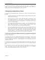
PARKING THE FORMSPRO 4503 TRACTORS FOR
SHIPMENT
In the event the printer ever needs to be shipped, the tractors should be “parked” toward the
front of the unit. To accomplish this, first remove the forms from all three tractor paths.
Then turn off the power switch on the side of the printer. Now press and hold the UNLOAD
button while you turn the power switch back on. Continue to hold the UNLOAD button until
the message “Park Shuttle ...” is displayed. After the shuttle stops moving and the park
shuttle message is no longer displayed, turn off the power switch and prepare the unit for
shipping.
Page 4-5
IN CASE OF DIFFICULTY
INTRODUCTION
A list is provided below which includes symptoms of possible problems and corresponding
causes and/or remedies. If you encounter a problem which you cannot solve with the
information in the following list, the company that sold you the printer can provide you with
local technical assistance and/or repairs. If you need further assistance, please contact
Printek, Inc. at 800-DOT-INFO (800-368-4636) and ask for “Customer Service” to obtain the
name of an authorized service center in your area, or to obtain factory repairs. DO NOT send
your printer to Printek, Inc. without first obtaining a Return Authorization number from
Printek's Customer Service department. When calling, please have available the name of the
company who sold you the printer, the date of purchase, the printer model number, the printer
serial number, and a list of any installed options (see option list on the back of your printer).
Also provide as much information as possible about the problem. If you return your printer
for repair, it is helpful if you can also return a print sample of the error if applicable.
Many authorized dealers, distributors, and service centers offer service contracts which
provide for the fastest possible repair for your printer. Printek, Inc. also provides several
types of factory level service contracts ranging from guaranteed 48 hour turnaround, to a
replacement printer shipped to you within 24 hours. For more information, contact the
company where you purchased the unit or contact Printek Customer Service at the above toll
free number.
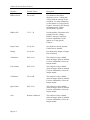
SYMPTOMS AND POSSIBLE CAUSES
Problem or Symptom
Possible Cause or Remedy
Green POWER LED
does not come on when
the printer is switched
on.
Power cord is not plugged into the wall outlet or the printer.
No power at the wall outlet.
Printer AC power fuse is blown (see “Replacing the AC Power
Fuse” later in this chapter).
Page 5-1
In Case of Difficulty
Problem or Symptom
Possible Cause or Remedy
“No/Wrong Ribbon”
message is displayed
when a ribbon cartridge
is actually installed.
The battery in the ribbon sensing circuit may need to be replaced
(normal battery life exceeds ten years).
Poor print quality.
Worn or damaged ribbon.
A non-Printek ribbon has been installed. While not
recommended, the use of non-Printek ribbons is allowed.
However, only Printek ribbons will allow the ribbon sensing
system and ribbon wear indicator to function. To configure your
printer to be able to use non-Printek ribbons, refer to the
appendix titled “Advanced Control Panel Features”.
Ribbon not installed properly on drive mechanism.
Note: If the ribbon cartridge and/or fabric is damaged, replace it
with a new ribbon. Continued use of a damaged ribbon may
cause damage to the ribbon drive mechanism or the print head.
Poor print quality on
multipart forms.
The form requires the high impact character mode. Set Impact to
High in the form setup menu.
Poor carbon or carbonless form quality. Refer to “Selecting a
Quality Form” later in this section.
Paper misfeeds.
Obstruction in paper path. Check both printer and print stand.
Torn or ragged edge on paper.
Paper misaligned in tractors.
Left and right tractors too close to each other allowing paper to
“droop”.
Tractor doors not closed.
Paper too difficult to pull from box (dragging on sides of box).
Remove forms from box or cut away sides of box.
Tractor blocking paper out detector.
Poorly constructed forms. Refer to “Selecting a Quality Form”
later in this section.
“MP: I/O Overflow”
error message.
Page 5-2
The printer's input buffer has been exceeded. Check the
interface setup to assure that the handshaking or flow control
method required by your computer has been selected. Also
check the cabling for proper pin-out or broken wires.
In Case of Difficulty
Problem or Symptom
Possible Cause or Remedy
“MP: Parity Error” error
message.
A serial character was received with improper parity. Check the
interface setup to assure that the parity (odd, even, ignored, or
none) is set to match the parity setting required by your
computer. Also check the cabling for intermittent connections
“PE: Head Stall” error
message.
Carriage path is obstructed. Clear the obstruction and turn the
printer off and back on again to clear the error.
Carriage shaft is dirty. Wipe completely with a clean cloth.
Ribbon cartridge is worn or damaged and will not advance
ribbon.
Other MP: or PE: error
message.
The printer has detected an internal error condition. Report the
message to an authorized service agent.
Will print barberpole,
but will not print data
from the computer.
The interface is not configured properly. Refer to the
“Operation” section and review the interface settings to make
sure they match what is being generated by the computer.
The interface cable is not wired properly. Refer to the
appropriate section or appendix for pin-out specifications for the
interface being used.
Paper drops out of the
tractors during load.
The paper out sensor is blocked. This may be caused by paper
that is extending above the tractors in another path or a tractor
that is blocking the paper out detector.
Page 5-3
In Case of Difficulty
USING THE HEX DUMP MODE
The Hex Dump mode provides a way to print, in a readable form, all of the data received by
the printer. This tool is often useful to programmers for diagnosing problems encountered
when sending the printer control codes and escape sequences used to control the various print
modes and setup features of the printer. Hex Dump may also be used to detect what
commands are being sent by a particular software application to help determine which
emulation mode is needed for that application.
To select Hex Dump, refer to the “Operation” section and review the information about
setting the emulation mode (“Mode:”) in the interface menu. Be sure to note the emulation
currently being used before you change it to Hex Dump.
A sample Hex Dump is shown below. Note that each line shows sixteen characters, first in
hexadecimal format, then in printable ASCII format. All unprintable ASCII characters
(printable characters are from 21 hex to 7E hex inclusive) are represented by a period.
54686973
20686578
75737472
666F726D
20697320
2064756D
61746520
61740D0A
61207361
7020746F
68657820
6D706C65
20696C6C
64756D70
This.is.a.sample
.hex.dump.to.ill
ustrate.hex.dump
format..
When the printer executes in hex dump mode, control characters and escape sequences sent to
the printer are not recognized or processed. The hexadecimal representation of the control
characters and escape sequences appears in the hex dump, but no special processing occurs.
In particular, note that ETX/ACK handshake will not operate properly in hex dump mode.
When an ETX is received by the printer, its hexadecimal representation is printed in the hex
dump, but no ACK is sent to the host computer. When you use the printer in hex dump
mode, we recommend that you configure the printer for parallel I/O, serial I/O with hardware
handshake, serial I/O with XON/XOFF handshake, or CX/TX if installed.
To exit hex dump, use setup to return the printer to the previous emulation mode.
Page 5-4
In Case of Difficulty
SELECTING A QUALITY FORM
Although the FormsPro 4000 series printers have been designed to handle difficult forms, you
may come across a form that does not feed reliably or provide adequate print quality on all
copies.
One of the main causes of paper misfeeds is a form that is “tented”. Tenting is a tent-like
bulge at the perforation when forms are unfolded from the box. The printer allows a
maximum form thickness of .025 inches, which a badly tented form may exceed.
Tenting is usually caused by glue drying on the perforation after the forms maker puts the
forms into the box, or forms which are not glued at all. Forms with solid glue lines which run
vertically down the entire form are the most susceptible. If you experience such a problem,
request “interrupted glue line” forms from your vendor. This method stops the glue
approximately three-quarters of the way down the form and then resumes gluing at the top of
the next form. The gluing should not begin too far below the top of the form or pages of the
form will be able to fan apart and be a potential cause of jamming.
Another area where not all forms are alike is in the quality of carbon paper used, or in the
way carbonless inks are applied. If the back copies of your form are too light, request a
quick-release carbon or a higher quality carbonless inking method.
REPLACING THE AC POWER FUSE
Use the following procedure to replace the fuse if it should ever become necessary:
1.
Unplug the line cord from the back of the printer.
2.
Use a phillips screwdriver to remove the two black screws that are located just above
the line cord socket.
3.
Open the case like you would normally do when you load paper.
4.
As viewed from the front of the printer, locate the AC cover in the right rear corner of
the chassis. Then remove the screw that secures the cover to the bottom of the chassis.
5.
Carefully remove the AC cover to expose the AC wiring.
6.
Carefully remove the fuse from the filter circuit board. Be careful not to damage the
fuse mounting clips.
7.
For continued protection from the risk of fire or damage to the printer, replace the fuse
only with the same type fuse. Refer to the label on the AC cover for information about
the fuse.
8.
Reposition the AC cover over the AC wiring. Be careful not to pinch any wires
between the cover and the chassis. Then reinstall the three screws.
Page 5-5
In Case of Difficulty
9.
Reconnect the line cord to its socket on the rear of the printer.
The printer is now ready to be put back into service.
Page 5-6
APPENDIX A”
ADVANCED CONTROL PANEL FEATURES
The printer's control panel has two additional menus for use by the system administrator.
These are the “Setup: OPTIONS” and “Setup: SECURITY” menus. The OPTIONS menu is
used to inform the printer of any “over all” operating variables and of some optional products
which may be installed.
Setup: OPTIONS
The option menu is the third setup menu. To enter it, first take the printer offline. Then press
and hold the setup button for approximately 4-1/2 seconds until “Setup: OPTIONS” appears
on the display and the bell beeps three times. Note that while you hold the button, “Setup:
FORMS” and “Setup: INTERFACE” are displayed as you pass through those menus. At this
time you are able to view and/or edit the values for the option functions listed below.
Although you may select functions with either the FUNCTION UP or FUNCTION DOWN
buttons, they are listed here in the order of function up.
Function
Possible Values
Description
Max Form #:
0 through 9
Sets the last form number to be
displayed for operator selection
with the FORM SELECT button or
while in the “Setup: FORMS”
menu.
Note that when setting this value
that you may not select a value less
than the form currently selected
when setup was entered, or less
than the form currently selected in
the “Setup: FORMS” menu.
Page A-1
Advanced Control Panel Features
Function
Possible Values
Description
Ribbon Check:
On* or Off
Sets whether or not ribbon
checking is active. Turning this
off may limit the warranty on the
print head. For more information,
see the chapter on “Using Special
Features” and refer to the warranty
information in the “Printer
Specifications” appendix.
Ribbon Life:
15*, 5 - 30
Sets the number of characters to be
printed before the “Change
Ribbon” message is displayed.
For more information, see the
chapter on “Using Special
Features”.
Paper Cutter:
Yes or No*
Sets whether or not the optional
FormsCutter is installed.
Imager:
Yes or No*
Sets whether the Imager or Imager
Plus is installed.
Translation:
Off* or On
This function is only available
when an Imager option is installed.
For more information, refer to the
Imager manual.
Free Format:
Off* or On
This function is only available
when an Imager option is installed.
For more information, refer to the
Imager manual.
Terminator:
LF* or CR
This function is only available
when an Imager option is installed.
For more information, refer to the
Imager manual.
Ignore Char:
Off* or On
This function is only available
when an Imager option is installed.
For more information, refer to the
Imager manual.
Zero:
Normal or Slashed*
This function is only available
when an Imager option is installed.
For more information, refer to the
Imager manual.
Page A-2
Advanced Control Panel Features
Function
Possible Values
Description
Ignore Col 1:
Yes or No*
This function is only available
when an Imager option is installed.
For more information, refer to the
Imager manual.
Control Char:
^*, ~, !, ?, ;, ', |, or \
This function is only available
when an Imager option is installed.
For more information, refer to the
Imager manual.
Bar Codes:
Hi-Res*, Med-Res,
Lo-Res
This function is only available
when an Imager option is installed.
For more information, refer to the
Imager manual.
Page A-3
Advanced Control Panel Features
Setup: SECURITY
This menu offers a security feature for environments where it is not desirable for the operator
to be able to modify either the values of form related functions, interface related functions, or
option related functions. With the security feature enabled, the operator will be able to
inspect or view the values of the various functions, but will not be able to change or edit these
values.
The security menu is the fourth setup menu. To enter it, first place the printer offline. Then
press and hold the setup button for approximately 8-1/2 seconds until “Setup: SECURITY”
appears on the display and the bell beeps four times. Note that while you hold the button,
“Setup: FORMS”, “Setup: INTERFACE”, and “Setup: OPTIONS” are displayed as you pass
through those menus. At this time you are able to view and/or edit the values for the security
functions listed below. Although you may select functions with either the FUNCTION UP or
FUNCTION DOWN buttons, they are listed here in the order of function up.
Function
Possible Values
Description
Forms:
Edit*, View, or Init
Selects whether an operator can
modify, only look at, or initialize
function values in the forms menu.
Edit allows the operator to look at
and/or modify form function values.
View allows the operator to only
look at form function values. No
values can be modifed.
Init causes all form function values
to be set to the factory default
settings for all forms. When this
completes, the security value is set
to Edit.
Page A-4
Advanced Control Panel Features
Function
Possible Values
Description
Interface:
Edit*, View, or Init
Selects whether an operator can
modify, only look at, or initialize
function values in the interface
menu.
Edit allows the operator to look at
and/or modify interface function
values.
View allows the operator to only
look at the interface function values.
No values can be modified.
Init causes all interface function
values to be set to the factory
default settings. When this
completes, the security value is set
to Edit.
Options:
Edit*, View, or Init
Selects whether an operator can
modify, only look at, or initialize
function values in the options menu.
Edit allows the operator to look at
and/or modify option function
values.
View allows the operator to only
look at option function values. No
values can be modifed.
Init causes all option function values
to be set to the factory default
settings. When this completes, the
security value is set to Edit.
Clone:
Off*, Transmit, Receive
Used for cloning setup information
to or from a printer. For more
information, see the appendix on
“Cloning Printer Setup”.
Page A-5
Advanced Control Panel Features
Page A-6
APPENDIX B
OPTIONAL RS-422 INTERFACE
A 25-pin female “D” type connector is located on the rear of the printer above the power
connector. Connect a shielded cable between your computer and this connector. The pin-out
for this connector is shown below.
Pin
7
9
10
11
12
Signal
Ground
RI+ Receive Data.
RI- Receive Data.
DO+ Transmit Data.
DO- Transmit Data.
RS-422 Serial Interface Connector
To configure your printer for serial data, more information is required than for some other
interfaces. In particular, you must know the baud rate, the number of data bits, the type of
parity checking, and the handshaking or flow control method required by your computer.
Check your computer manual or contact your computer dealer for this information.
Turn the printer on and enter the interface menu as described in the “Installation and Quick
Setup” section. Press the FUNCTION UP button to display “I/O: n”. Then press the
VALUE UP button until “n” is “Serial”.
The factory default values for the RS-422 serial configuration are 9600 baud, 8 data bits, no
parity, XON/XOFF handshake enabled, and ETX/ACK handshake disabled. If your
computer requires you to change any of these parameters, please refer to “Entering the
Interface Setup Menu” in the “Operation” section of this manual. Otherwise, simply press
SETUP again to exit the setup mode and reset the printer. The serial interface with the above
parameters is now active.
Page B-1
APPENDIX C
OPTIONAL COAXIAL/TWINAXIAL INTERFACE
This appendix describes the configuration of the optional coaxial/twinaxial interface which
replaces the standard parallel interface. The factory default settings in the Interface setup
menu are Mode: Epson, I/O: CX/TX, and Data Bits: 8.
For your convenience, a parallel interface is also provided as part of the coaxial/twinaxial
interface. The interface will automatically switch to receive data from either the
coaxial/twinaxial port or the parallel port, after the timeout specified on the configuration DIP
switches (SW1-7 & SW1-8). When data is received at the coaxial/twinaxial port, the
interface will automatically switch to Printek emulation and select the EBCDIC font. The
interface will automatically switch the printer to the default emulation selected in the
Interface menu and select the parameters set for the current form in the Forms menu when
data is received at the parallel port. For information about changing emulations and/or how
to command other special printer functions via software control sequences, refer to the
Programmer's Manual.
This interface is supplied with two connector cables. One cable provides a BNC type
connector for coaxial connection. The other cable is a “smart T” for twinaxial connections,
and automatically provides line termination if you have only one twinaxial cable connected.
The interface also configures itself automatically for either coaxial or twinaxial operation,
depending upon which of the above cables is attached to the 15 pin “D” connector. Some of
the configuration DIP switches will also have different meanings depending upon which
cable is attached. Refer to the following coaxial or twinaxial section as appropriate for these
switch definitions and other configuration information.
COAXIAL OPERATION
This interface automatically configures itself for coaxial operation if the 15 pin “D” to BNC
adapter cable is plugged in when power is applied to the printer.
The coaxial interface allows you to attach a FormsPro 4000 series printer to IBM mainframes
via 3274, 3276, or 3174 Cluster Controllers, and emulates either the IBM 3287 or 3262
printer. This interface supports the three types of data transmitted from the Cluster
Controller. These types are dependent upon the controller type, the system configuration, and
the type of communication used. The types are:
Page C-1
Optional Coaxial/Twinaxial Interface
DSC (Data Stream Compatible) 3270 type LU3
DSE (Data Stream Emulation) SNA type LU3
SCS (SNA Character Stream) SNA type LU1
In the DSC/DSE type LU3 mode, both formatted and unformatted data streams are supported.
Interface diagnostics are available at the end of this appendix in the section titled
“Coaxial/Twinaxial Interface Diagnostics”.
CX/TX Interface.
Option Switches When Configured for Coaxial Operation
The dipswitches as shown above have the following meanings when the interface is
configured for coaxial operation. An asterisk (*) indicates the factory default setting.
Switch/Position
Function
SW1-1 OFF*
SW1-1 ON
Select IBM 3287 Emulation.
Select IBM 3262 Emulation.
SW1-2 OFF*
Reserved for future use.
SW1-3 OFF*
Reserved for factory use.
SW1-4 OFF*
Reserved for factory use.
SW1-5 OFF*
Set default Maximum Print Position to 132
columns.
Set default Maximum Print Position to none.
SW1-5 ON
Page C-2
Optional Coaxial/Twinaxial Interface
SW1-6 OFF*
SW1-6 ON
Set default Maximum Print Line to none.
Set default Maximum Print Line to 66 lines.
SW1-7 SW1-8
OFF* OFF*
ON
OFF
OFF ON
ON
ON
SW2-1 OFF*
Parallel multiplexer timeout.
Short (15 seconds)
Medium.
Long.
Very Long (60 seconds).
Run.
Addr 0 = Logical Buffer Size is 1920.
Addr 1 = Logical Buffer Size is 960.
Addr 2 = Logical Buffer Size is 1920.
Addr 3 = Logical Buffer Size is 2560.
Addr 4= Logical Buffer Size is 3440.
Addr 5 = Logical Buffer Size is 3864.
Addr 6 = Logical Buffer Size is 1920.
Addr 7-9 = n/a.
SW2-1 ON
Test.
Addr 0-6 = Code Dump.
Addr 7 = Configuration Printout.
Addr 8 = Print Test.
Addr 9 = Loop Test.
SW2-2 OFF*
SW2-2 ON
Send 5E Hex (^) for Logical Not.
Send E1 Hex ( ) for Logical Not.
SW2-3 OFF*
SW2-3 ON
Enable Null Line Suppression in LU3
Formatted Mode.
Disable Null Line Suppression.
SW2-4 OFF*
SW2-4 ON
Paper Errors Not Reported.
Paper Errors Reported.
Page C-3
Optional Coaxial/Twinaxial Interface
TWINAXIAL OPERATION
When you attach devices such as the FormsPro 4000 series printer to the System 3X, the
devices must be configured onto the system by device type, so that they may be supported
and used to their utmost ability. Once a device has been configured onto the system, the
system utilizes the device type information to communicate with the device. The device
responds to the system's polls and commands in accordance to its device description. The
system being configured for a 4214 Model 01 printer, for example, as address 10 (port 1,
device 0) will expect a response from a 4214 Model 01 at that address location. Should there
be a 5256 Model 3 printer at device address 10 when the system sends a print job to the
printer, the system would generate a “HARDWARE FAILURE” error message (for System
38) or a “PROGRAM ERROR” error message (for Systems 34/36). It is very important to
observe the device and System 3X configurations.
The FormsPro 4000 series printers may emulate three different IBM models as listed in the
following table. The DIP switches allow you to select these emulations. As shipped from the
factory, the printer is set for 4214 Model 2 emulation.
CX/TX Interface.
Page C-4
Optional Coaxial/Twinaxial Interface
Option Switches When Configured for Twinaxial Operation
The dipswitches as shown above have the following meanings when the interface is
configured for twinaxial operation. An asterisk (*) indicates the factory default setting.
Switch/Position
Function
SW1-1
OFF*
ON
OFF
ON
Select Emulation
4214 Model 2.
5225 Model 3.
5256 Model 3
Reserved for future use.
SW1-2
OFF*
OFF
ON
ON
SW1-3 OFF*
Reserved for factory use.
SW1-4 OFF*
Reserved for factory use.
SW1-5
OFF*
ON
OFF
ON
Default Character Set.
Multinational.
U.S.A.
Austrian/German.
French Canadian.
SW1-6
OFF*
OFF
ON
ON
SW1-7 SW1-8
OFF* OFF*
ON
OFF
OFF ON
ON
ON
SW2-1 OFF*
SW2-1 ON
Parallel Multiplexer Timeout.
Short (15 seconds).
Medium.
Long.
Very Long (60 seconds).
Run.
Test.
Addr 0-6 = Code Dump.
Addr 7 = Configuration Printout.
Addr 8 = Print Test.
Addr 9 = Loop Test.
SW2-2 OFF*
SW2-2 ON
Send 5E Hex (^) for Logical Not.
Send E1 Hex ( ) for Logical Not.
SW2-3 OFF*
SW2-3 ON
Load Forms Enabled.
Load Forms Disabled.
SW2-4 OFF*
Reserved for future use.
Twinaxial Address Switch
The “ADDR” switch sets the logical device address. You may wish to use a small
screwdriver to turn the knob on this switch. Note that there is a black line on the side of this
knob which indicates the address that is currently selected. Only addresses 0 through 6 are
valid for twinaxial operation. Addresses 7, 8, and 9 are used for diagnostic purposes only and
are described later in this appendix in the section titled “Coaxial/Twinaxial Interface
Diagnostics”.
Page C-5
Optional Coaxial/Twinaxial Interface
Twinaxial Installation Preparation
When you attach a device to the System 3X cabling, be sure to observe the following:
1.
A maximum of only seven devices can attach to a twinax port (addresses 0
through 6).
2.
You cannot have duplicate addresses. For example: two devices with an address
of 00.
3.
The logical address does not have to correspond to the physical location of the
device on the twinax line.
4.
The printer emulation must match the device type for which the system is
configured.
5.
When you address a device, either at the device or configuring it onto the system,
remember that the address is comprised of two parts; the first is the PORT to
which the device is attached, and the second is the logical location of the device
or the device address. For example: ADDRESS 10 means the device is on PORT
1 with the address of 0, this is the number dialed onto the address switch of the
I/O on the printer.
6.
As a precaution, have the print jobs placed ON HOLD and have the terminals
SIGN OFF on the line that you are working on.
Getting On-line
This section will use the terms “Up Stream” and “Down Stream”. “Up Stream” describes a
device that is physically located closer to the system on the twinax line. “Down Stream”
describes a device physically located more distant from the system on the twinax line. For
example, if this printer is the third device on the line, the immediate “up stream” device
would be the second device on this line.
To put the printer on-line, perform the following steps:
Step 1 - Power down the printer.
Step 2 - If there are any active devices on the twinaxial line that the printer is going to be on,
you must:
a.
Disable or remove the line termination on the device immediately up stream.
b.
Place on hold any active jobs or spool file entries for any down stream
devices.
c.
Sign off any active down stream terminals and terminal type devices.
Step 3 - Observe the following and attach the twinax cable to the printer I/O:
Page C-6
Optional Coaxial/Twinaxial Interface
a.
If there is a device up stream from this printer, the twinaxial cable will
originate at the “OUT” connector of that device. The other end of this cable
attaches to either side of the “smart T” connector on the printer.
b.
If this printer is the first or only device on this line (only one cable is
attached to the printer), the “smart T” will automatically provide the proper
termination for the cable.
Step 4 - Verify that the address setting for this device is correct. Be certain that no address on
the line is duplicated. Remember that the black line on the side of the address knob
indicates the current address. Only addresses 0 through 6 are valid.
Step 5 - Turn the printer ON.
Step 6 - To ensure that the printer is properly installed, run the “WORK STATION
PRINTER TEST” from the IBM system according to the following instructions. If
you incur any problems while attempting to run this test, please refer to the section
on VERIFICATION PROBLEMS later in this appendix.
Access the terminal's SIGN ON screen. If this terminal is a 3180 or 3190, press the
“ALT, TEST” keys; otherwise press “CMD, BACKSPACE” to access the “Prime
Option” menu.
Perform the following steps to test the configuration:
a.
Select option “2” on the Prime Option Menu, “Work Station Printer
Verification”, to run the IBM printer verification test.
b.
Select this printer's ID number to run the test on this printer.
c.
Select the number of times you wish to print the Work Station
Verification Test. The possible selections are:
1
Print test 1 time.
2
Print test 2 times.
3
Print test 3 times.
4
Print test continuously.
d.
Select option “C” on the Work Station Printer Verification menu, when
you have finished printing the test. You will be returned to the “Prime
Option Menu”.
e.
Select option “C” on the Prime Option Menu, “End”, to EXIT the “Prime
Option Menu”.
Page C-7
Optional Coaxial/Twinaxial Interface
Twinaxial Verification Problems
If any problems occurred during the printer verification test:
a.
Verify that the printer has the correct address setting.
b.
Verify that the address in the system configuration matches the address setting on
the printer.
c.
Verify that the device type in the system configuration is correct for the type of
printer being emulated, such as: 4214, 5225, etc.
d.
Verify that the cable to the device immediately up stream on the twinax line is
correctly connected. That is, if there is an up stream device, does the cable from
that device originate at the “OUT” connection.
e.
Verify that the device immediately up stream is functioning properly.
f.
Verify that the device immediately down stream is functioning properly.
g.
Verify that the last device on the line is providing the proper line termination.
Also make sure that the last device on the line is the only device providing
termination.
If the problem remains after you have checked all of the above, you may use the diagnostics
described in the following section to verify that the interface and printer are functioning
properly. If you are still unable to complete the installation, contact your dealer or Printek
Technical Support for assistance.
Note: If you make any changes to cables, switch settings
or the configuration, power the printer down, pause, and
then power the printer up again.
COAXIAL/TWINAXIAL INTERFACE DIAGNOSTICS
This interface has its own built-in diagnostic programs to help you verify that the printer is
operating properly.
To use a diagnostic, first turn off the printer. Then select the desired diagnostic by setting the
interface switch SW2-1 to the test position (ON) and select the desired test as described
below with the address (ADDR) switch. Now power the printer back on.
Page C-8
Optional Coaxial/Twinaxial Interface
When finished running diagnostics, be sure to power off the printer, set SW2-1 to the run
position (OFF), select the proper address for your installation (if configured for twinaxial
operation), and power the printer back on.
Code Dump Mode (Address 0 through 6)
The code dump diagnostic allows you to print in hexadecimal format all data received by the
coaxial/twinaxial interface.
First line - The printable representation of the received EBCDIC character.
Unprintable characters (such as form feeds or nulls) will print as spaces.
Second line - The most significant nibble of the received EBCDIC character printed in
hexadecimal format.
Third line - The least significant nibble of the received EBCDIC character printed in
hexadecimal format.
For Example:
F
K
A H
D EBCDIC character received
02C002D02002C02C0403C0 Most significant nibble
CB629B2490FB11B8301441 Least significant nibble
This above example shows the printer receiving a Form Feed (0C) followed by a
system command to go to 8 lpi (2B C6 02 09).
Configuration Printout (Address 7)
This diagnostic provides you with a one page printout which describes the current
configuration.
Print Test (Address 8)
Selecting this diagnostic causes a test pattern to be printed. This tests the internal interface to
printer electronics connections.
Loop Test (Address 9)
This diagnostic tests the internal interface electronics. When performing this test, the coaxial
or twinaxial adapter cable must be attached to the printer, but not connected to the host
computer. When complete, a “Loop test passed” or “Loop test failed” message will be
printed.
Diagnostic Problems Checklist
If the printer's built-in diagnostic tests do not perform as described above then:
Page C-9
Optional Coaxial/Twinaxial Interface
a.
Verify the printer configuration.
b.
Check all of the installation connections.
c.
Rerun the diagnostic. If the problem persists, contact your dealer or Printek
Technical Support for technical assistance. If possible, have the configuration
printout from the Address 7 diagnostic available when you call.
Page C-10
APPENDIX D
OPTIONAL BUFFER EXPANSION
The FormsPro 4000 series printers are available with an optional buffer expansion that
increases the input buffer from 4K to 28K characters. This option can be installed either at
the factory or in the field. Field installation, as described below, should be performed only
by qualified service personnel. For installation, please contact the company who sold you the
printer or contact Printek, Inc. Customer Service at 800-368-4636 for the name of the
authorized service center nearest you.
CAUTION: The buffer IC as well as other components of
the printer can be damaged by static electricity. When
you install this option, try to do so in an uncarpeted area
if possible. Before touching the printer electronics, touch
the metal case of the printer to discharge any static
charge you may be carrying.
1.
Turn the printer off.
2.
Remove the three screws on the rear of the unit that secure the top cover in place.
Then slide the top cover out of the back of the printer to expose the main circuit
board.
Page D-1
Optional Buffer Expansion
1
1. Electronics Cover Screws.
3.
Locate the memory IC at U29 and its associated jumper at J6. Note the
orientation of the notch on the end of the IC at U29 and the location of the
shorting plug at J6.
J6
Front
U29 Notched End
Buffer and Jumper Locations on Main Circuit Board
4.
Page D-2
Remove the IC at U29 and replace it with the one supplied with the upgrade kit.
Be sure that the notch is oriented the same as the one just removed (notched end
toward the front of the printer). Also be careful not to bend any of the pins on
the IC while installing it into the socket.
Optional Buffer Expansion
5.
Move the shorting plug at J6 from its location on pins 2 & 3 to pins 1 & 2 (pin 1
is toward the front of the printer).
6.
Reinstall the lid and screws.
7.
Turn the printer on. If the installation was performed incorrectly, “MP: Bad
RAM Chip” will be displayed on the LCD display. If this error occurs, inspect
the IC for any bent pins and inspect the shorting plug for proper installation.
8.
Indicate on the Installed Options label on the rear of the printer that the buffer
expansion has been installed.
Page D-3
APPENDIX E
ASCII CHARACTER TABLES
ASCII CONTROL CODE DEFINITIONS
The following table is provided as a reference to the control character descriptions as
provided by the ASCII definition. Not all of these definitions are supported by the
FormsPro 4000 series printers and some are emulation dependent. For more information,
refer to the Programmer's Manual.
Control
Code
Hexadecimal
Value
NUL
SOH
STX
ETX
EOT
ENQ
ACK
BEL
BS
HT
LF
VT
FF
CR
SO
SI
DLE
DC1
DC2
DC3
DC4
NAK
SYN
ETB
CAN
EM
SUB
ESC
FS
GS
RS
US
00
01
02
03
04
05
06
07
08
09
0A
0B
0C
0D
0E
0F
10
11
12
13
14
15
16
17
18
19
1A
1B
1C
1D
1E
1F
Description
Null
Start of Heading
Start of Text
End of Text
End of Transmission
Enquiry
Acknowledge
Bell
Backspace
Horizontal Tabulation
Line Feed
Vertical Tabulation
Form Feed
Carriage Return
Shift Out
Shift In
Data Link Escape
Device Control 1 (XON)
Device Control 2
Device Control 3 (XOFF)
Device Control 4
Negative Acknowledge
Synchronous Idle
End of Transmission Block
Cancel
End of Medium
Substitute
Escape
File Separator
Group Separator
Record Separator
Unit Separator
Page E-1
ASCII Character Tables
Epson FX Fast Draft
Epson FX Draft
Epson FX Letter Quality
Page E-2
ASCII Character Tables
PC Fast Draft
PC Draft
PC Letter Quality
Page E-3
ASCII Character Tables
EBCDIC Fast Draft
EBCDIC Draft
EBCDIC Letter Quality
Page E-4
ASCII Character Tables
Latin 2 (Slavic) Fast Draft
Latin 2 (Slavic) Draft
Latin 2 (Slavic) Letter Quality
Page E-5
ASCII Character Tables
OCR A
OCR B
Page E-6
ASCII Character Tables
DECIMAL-TO-OCTAL-TO-HEXADECIMAL-TO-ASCII
CONVERSION TABLE
Dec
0
1
2
3
4
5
6
7
8
9
10
11
12
13
14
15
16
17
18
19
20
21
22
23
24
25
26
27
28
29
30
31
32
33
34
35
36
37
38
39
40
41
42
43
44
45
46
47
48
49
50
51
52
53
54
55
56
57
58
59
60
61
62
63
Oct
000
001
002
003
004
005
006
007
010
011
012
013
014
015
016
017
020
021
022
023
024
025
026
027
030
031
032
033
034
035
036
037
040
041
042
043
044
045
046
047
050
051
052
053
054
055
056
057
060
061
062
063
064
065
066
067
070
071
072
073
074
075
076
077
HexASCII
00 NUL
01 SOH
02 STX
03 ETX
04 EOT
05 ENQ
06 ACK
07 BEL
08
BS
09
HT
0A LF
0B VT
0C
FF
0D CR
0E SO
0F
SI
10 DLE
11 XON
12 DC2
13 XOFF
14 DC4
15 NAK
16 SYN
17 ETB
18 CAN
19 EM
1A SUB
1B ESC
1C
FS
1D GS
1E RS
1F
US
20
SP
21
!
22
"
23
#
24
$
25
%
26
&
27
'
28
(
29
)
2A
*
2B
+
2C
,
2D
2E
.
2F
/
30
0
31
1
32
2
33
3
34
4
35
5
36
6
37
7
38
8
39
9
3A
:
3B
;
3C
<
3D
=
3E
>
3F
?
Dec
64
65
66
67
68
69
70
71
72
73
74
75
76
77
78
79
80
81
82
83
84
85
86
87
88
89
90
91
92
93
94
95
96
97
98
99
100
101
102
103
104
105
106
107
108
109
110
111
112
113
114
115
116
117
118
119
120
121
122
123
124
125
126
127
Oct
100
101
102
103
104
105
106
107
110
111
112
113
114
115
116
117
120
121
122
123
124
125
126
127
130
131
132
133
134
135
136
137
140
141
142
143
144
145
146
147
150
151
152
153
154
155
156
157
160
161
162
163
164
165
166
167
170
171
172
173
174
175
176
177
HexASCII
40
@
41
A
42
B
43
C
44
D
45
E
46
F
47
G
48
H
49
I
4A
J
4B
K
4C
L
4D
M
4E
N
4F
O
50
P
51
Q
52
R
53
S
54
T
55
U
56
V
57
W
58
X
59
Y
5A
Z
5B
[
5C
\
5D
]
5E
^
_
5F
60
`
61
a
62
b
63
c
64
d
65
e
66
f
67
g
68
h
69
i
6A
j
6B
k
6C
l
6D
m
6E
n
6F
o
70
p
71
q
72
r
73
s
74
t
75
u
76
v
77
w
78
x
79
y
7A
z
7B
{
7C
|
7D
}
7E
~
7F DEL
Dec
128
129
130
131
132
133
134
135
136
137
138
139
140
141
142
143
144
145
146
147
148
149
150
151
152
153
154
155
156
157
158
159
160
161
162
163
164
165
166
167
168
169
170
171
172
173
174
175
176
177
178
179
180
181
182
183
184
185
186
187
188
189
190
191
Oct
200
201
202
203
204
205
206
207
210
211
212
213
214
215
216
217
220
221
222
223
224
225
226
227
230
231
232
233
234
235
236
237
240
241
242
243
244
245
246
247
250
251
252
253
254
255
256
257
260
261
262
263
264
265
266
267
270
271
272
273
274
275
276
277
Hex
80
81
82
83
84
85
86
87
88
89
8A
8B
8C
8D
8E
8F
90
91
92
93
94
95
96
97
98
99
9A
9B
9C
9D
9E
9F
A0
A1
A2
A3
A4
A5
A6
A7
A8
A9
AA
AB
AC
AD
AE
AF
B0
B1
B2
B3
B4
B5
B6
B7
B8
B9
BA
BB
BC
BD
BE
BF
Dec
192
193
194
195
196
197
198
199
200
201
202
203
204
205
206
207
208
209
210
211
212
213
214
215
216
217
218
219
220
221
222
223
224
225
226
227
228
229
230
231
232
233
234
235
236
237
238
239
240
241
242
243
244
245
246
247
248
249
250
251
252
253
254
255
Oct
300
301
302
303
304
305
306
307
310
311
312
313
314
315
316
317
320
321
322
323
324
325
326
327
330
331
332
333
334
335
336
337
340
341
342
343
344
345
346
347
350
351
352
353
354
355
356
357
360
361
362
363
364
365
366
367
370
371
372
373
374
375
376
377
Hex
C0
C1
C2
C3
C4
C5
C6
C7
C8
C9
CA
CB
CC
CD
CE
CF
D0
D1
D2
D3
D4
D5
D6
D7
D8
D9
DA
DB
DC
DD
DE
DF
E0
E1
E2
E3
E4
E5
E6
E7
E8
E9
EA
EB
EC
ED
EE
EF
F0
F1
F2
F3
F4
F5
F6
F7
F8
F9
FA
FB
FC
FD
FE
FF
Page E-7
APPENDIX F
CONTROL CODE AND ESCAPE SEQUENCE
SUMMARIES
ANSI x3.64 Emulation
BEL
BS
CR
CSI
ESC D
ESC E
ESC ESC n
ESC H
ESC J
ESC K
ESC L
ESC [ n1 ; n2 SP G
ESC [ n `
ESC [ n a
ESC [ n d
ESC [ n e
ESC [ g
ESC [ 0 g
ESC [ 1 g
ESC [ 2 g
ESC [ 3 g
ESC [ 4 g
ESC [ 20 h
ESC [ 20 l
ESC [ n m
ESC c
ETX
FF
HT
HTS
IND
LF
NEL
PLD
PLU
VT
VTS
Bell
Backspace
Carriage Return
Control Sequence Introducer
Line Feed
New Line
Select Software Interface n
Set Horizontal Tab Stop
Set Vertical Tab Stop
Partial Line Down
Partial Line Up
Set Character and Line Spacing
Absolute Horizontal Tab
Relative Horizontal Tab
Absolute Vertical Tab
Relative Vertical Tab
Clear Horizontal Tab Stop
Clear Horizontal Tab Stop
Clear Vertical Tab Stop
Clear All Horizontal Tab Stops
Clear All Horizontal Tab Stops
Clear All Vertical Tab Stops
Select Automatic Carriage Return
Cancel Automatic Carriage Return
Select Graphic Rendition
Reset
End of Text
Form Feed
Horizontal Tab
Set Horizontal Tab Stop
Line Feed
Line Feed
New Line
Partial Line Down
Partial Line Up
Vertical Tab
Set Vertical Tab Stop
Page F-1
Control Code and Escape Sequence Summaries
Epson FX Emulation
BEL
BS
CAN
CR
DC2
DC3
DC4
DEL
ESC ! n
ESC #
ESC $ n1 n2
ESC * m n1 n2 data
ESC - n
ESC 0
ESC 1
ESC 2
ESC 3 n
ESC 4
ESC 5
ESC 6
ESC 7
ESC <
ESC =
ESC >
ESC @
ESC A n
ESC B n1 n2 ... nx NUL
ESC C NUL n
ESC C n
ESC D n1 n2 ... nx NUL
ESC E
ESC EM n
ESC ESC n
ESC F
ESC G
ESC H
ESC I n
ESC J n
ESC K n1 n2 data
ESC L n1 n2 data
ESC M
ESC N n
ESC O
ESC P
ESC Q n
ESC R n
ESC S n
ESC SI
ESC SO
ESC T
ESC U n
ESC W n
ESC Y n1 n2 data
ESC Z n1 n2 data
ESC \ n1 n2
ESC g
ESC j n
ESC k n
Page F-2
Bell
Backspace
Cancel Line
Carriage Return
Cancel Condensed Mode
Deselect Printer
Cancel Double-Wide Mode (one line)
Delete Character
Master Print Mode Select
Cancel MSB Control
Absolute Horizontal Tab
m DPI Graphics
Underline Mode
Select 8 LPI
Set Line Spacing to 7/72"
Select 6 LPI
Set Line Spacing to n/216"
Select Italic Mode
Cancel Italic Mode
Enable Printing of High Symbols
Disable Printing of High Symbols
Unidirectional Mode (one line)
Set MSB to 0
Set MSB to 1
Reset
Set Line Spacing to n/72"
Set Vertical Tab Stops
Set Form Length in Inches
Set Form Length in Lines
Set Horizontal Tab Stops
Select Emphasized Mode
Load Form
Select Software Interface n
Cancel Emphasized Mode
Select Double-Strike Mode
Cancel Double-Strike Mode
Printing of Low Symbols
Variable Distance Line Feed
60 DPI Graphics
120 DPI Graphics
Select 12 CPI
Set Perforation Skip
Cancel Perforation Skip
Select 10 CPI
Set Right Margin
Select International Character Set
Select Subscript or Superscript Mode
Select Condensed Mode
Select Double-Wide Mode (one line)
Cancel Subscript and Superscript Mode
Unidirectional Mode
Double-Wide Mode
High Speed 120 DPI Graphics
High Speed 240 DPI Graphics
Relative Horizontal Tab
Select 15 CPI
Variable Distance Reverse Line Feed
Select Font
Control Code and Escape Sequence Summaries
Epson FX Emulation (continued)
ESC l n
ESC t n
ESC w n
ESC x n
ETX
FF
HT
LF
SI
SO
VT
XOFF
Set Left Margin
Character Table (Italic vs. Extended)
Double-High Mode
Select Draft or Letter Quality
End of Text
Form Feed
Horizontal Tab
Line Feed
Select Condensed Mode
Select Double-Wide Mode (one line)
Vertical Tab
Deselect Printer
Page F-3
Control Code and Escape Sequence Summaries
IBM Proprinter Emulation
BEL
BS
CAN
CR
DC2
DC4
ESC - n
ESC 0
ESC 1
ESC 2
ESC 3 n
ESC 4
ESC 5 n
ESC 6
ESC 7
ESC :
ESC A n
ESC B n1 n2 ... nx NUL
ESC C NUL n
ESC C n
ESC D n1 n2 ... nx NUL
ESC E
ESC ESC n
ESC F
ESC G
ESC H
ESC I n
ESC J n
ESC K n1 n2 data
ESC L n1 n2 data
ESC N n
ESC O
ESC Q n
ESC R
ESC S n
ESC SI
ESC SO
ESC T
ESC U n
ESC W n
ESC X n1 n2
ESC Y n1 n2 data
ESC Z n1 n2 data
ESC [ @ n1 n2 m1 m2 m3 m4
ESC \ n1 n2
ESC ^ n
ETX
FF
HT
LF
SI
SO
VT
Page F-4
Bell
Backspace
Cancel Line
Carriage Return
Select 10 CPI
Cancel Double-Wide Mode (one line)
Underline Mode
Select 8 LPI
Set Line Spacing to 7/72"
Start Line Spacing
Set Line Spacing to n/216"
Set Top of Form
Automatic Line Feed
Select Character Set 2
Select Character Set 1
Select 12 CPI
Set Line Spacing to n/72"
Set Vertical Tab Stops
Set Form Length in Inches
Set Form Length in Lines
Set Horizontal Tab Stops
Select Emphasized Mode
Select Software Interface n
Cancel Emphasized Mode
Select Double-Strike Mode
Cancel Double-Strike Mode
Select Print Mode
Variable Distance Line Feed
60 DPI Graphics
120 DPI Graphics
Set Perforation Skip
Cancel Perforation Skip
Deselect Printer
Reset Horizontal and Vertical Tab Stops
Select Subscript or Superscript Mode
Select Condensed Mode
Select Double-Wide Mode (one line)
Cancel Subscript and Superscript Mode
Unidirectional Mode
Double-Wide Mode
Set Left and Right Margin
High Speed 120 DPI Graphics
High Speed 240 DPI Graphics
Double-High Mode
Print Characters
Print Single Character
End of Text
Form Feed
Horizontal Tab
Line Feed
Select Condensed Mode
Select Double-Wide Mode (one line)
Vertical Tab
Control Code and Escape Sequence Summaries
LA-120 Emulation
BEL
BS
CR
CSI
DEL
ESC ( a
ESC 1
ESC 2
ESC 3
ESC 4
ESC D
ESC E
ESC ESC n
ESC H
ESC J
ESC [
ESC [ n `
ESC [ n a
ESC [ c
ESC [ 0 c
ESC [ n d
ESC [ n e
ESC [ g
ESC [ 0 g
ESC [ 1 g
ESC [ 2 g
ESC [ 3 g
ESC [ 4 g
ESC [ 20 h
ESC [ 20 l
ESC [ n m
ESC [ n1 ; n2 r
ESC [ n1 ; n2 s
ESC [ n t
ESC [ n1 ; n2 ; ... nx u
ESC [ n1 ; n2 ; ... nx v
ESC [ n w
ESC [ n z
ETX
FF
HT
HTS
IND
LF
NEL
VT
VTS
Bell
Backspace
Carriage Return
Control Sequence Introducer
Delete
Select International Character Set
Set Horizontal Tab Stop
Clear All Horizontal Tab Stops
Set Vertical Tab Stop
Clear All Vertical Tab Stops
Line Feed
New Line
Select Software Interface n
Set Horizontal Tab Stop
Set Vertical Tab Stop
Control Sequence Introducer
Absolute Horizontal Tab
Relative Horizontal Tab
Printer Identification
Printer Identification
Absolute Vertical Tab
Relative Vertical Tab
Clear Horizontal Tab Stop
Clear Horizontal Tab Stop
Clear Vertical Tab Stop
Clear All Horizontal Tab Stops
Clear All Horizontal Tab Stops
Clear All Vertical Tab Stops
Select Automatic Carriage Return
Cancel Automatic Carriage Return
Select Graphic Rendition
Set Top and Bottom Margins
Set Left and Right Margin
Set Form Length in Lines
Set Horizontal Tab Stops
Set Vertical Tab Stops
Set Character Spacing
Set Line Spacing
End of Text
Form Feed
Horizontal Tab
Set Horizontal Tab Stop
Line Feed
Line Feed
New Line
Vertical Tab
Set Vertical Tab Stop
Page F-5
Control Code and Escape Sequence Summaries
Simple TTY Emulation
BEL
BS
CR
ESC ESC n
ETX
FF
HT
LF
VT
Page F-6
Bell
Backspace
Carriage Return
Select Software Interface n
End of Text
Form Feed
Horizontal Tab
Line Feed
Vertical Tab
Control Code and Escape Sequence Summaries
Printek Emulation
BEL
BS
CR
DC3
ESC # m n1 n2 data
ESC %
ESC * m n1 n2 data
ESC @
ESC A n
ESC B n
ESC C
ESC D n
ESC E n
ESC ESC n
ESC F n
ESC FF n
ESC G n
ESC H n1 n2
ESC HT n1 n2 ... nx NUL
ESC I n
ESC L n
ESC LF n
ESC R
ESC S n
ESC SP n
ESC U n
ESC V n1 n2
ESC VT n1 n2 ... nx NUL
ESC W n
ESC \ n
ESC ^
ESC _ n
ETX
FF
HT
LF
VT
XOFF
Bell
Backspace
Carriage Return
Deselect Printer
m DPI Graphics
Line Feed Boundary
m DPI Graphics
Reset
Automatic Modes
Auto Cut Mode
Cut
Double-Strike Mode
Emphasized Mode
Select Software Interface n
Select Font
Set Form Length in Lines
Modify Print Head Gap
Set Left and Right Margin
Set Horizontal Tab Stops
Set Print Head Force
Load Form
Set Line Spacing to n/288"
Reset Horizontal and Vertical Tab Stops
Select Script Modes
Set character Spacing
Unidirectional Mode
Set Top and Bottom Margins
Set Vertical Tab Stops
Double-Wide Mode
Print Single Character
Reverse Line Feed
Underline Mode
End of Text
Form Feed
Horizontal Tab
Line Feed
Vertical Tab
Deselect Printer
Page F-7
APPENDIX G
PRINTER RESET CONDITIONS
The following list describes conditions that are assumed whenever power is applied to the
printer, the SETUP mode is exited, or a reset escape sequence is received (when the printer is
operating in an emulation mode that supports such a sequence).
This list includes all variables that you can modify for all emulations, even though some
emulations cannot modify all of the variables shown. Refer to the appropriate section of this
manual for the emulation you are using.
Variable
character pitch
left margin
right margin
line pitch
form length
top margin
bottom margin
font
impact mode
language
normal/slashed zero
auto cut mode
unidirectional mode
top of form
text in an incomplete line
input buffer
control of data bit 8
control character symbols
italics
double high
double strike
double wide
emphasized
superscript/subscript
underline
horizontal tabs
vertical tabs
Reset Condition
according to current form setup
according to current form setup
according to current form setup
according to current form setup
according to current form setup
according to current form setup
according to current form setup
according to current form setup
according to current form setup
according to current form setup
according to current form setup
according to current form setup
according to current form setup
set to current position
discarded
cleared (unless reset from host)
accepted as received
according to interface setup
off
off
off
off
off
off
off
to every eight columns
cleared
Page G-1
Printer Reset Conditions
Page G-2
APPENDIX H
CLONING PRINTER SETUP
The FormsPro 4300 and 450X printers contain a significant amount of setup information,
including form parameters for 10 different forms, I/O interface parameters, and option
parameters for options like the FormsCutter and Imager/ImagerPlus.
The printer cloning feature allows the setup information in one printer to be copied to another
printer. Once one printer is setup exactly as desired, the setup information can be easily and
precisely duplicated in other printers. This is very helpful if a company uses many printers,
all of which must be configured the same way. It may also be helpful if one printer is to be
replaced by another.
CLONING FROM PRINTER TO PRINTER
To copy the setup information from one printer to another, the following steps are required:
1.
Connect the two printers with an RS-232 Null Modem Cable with DB-25 Male
connectors on each end. While most null modem cables provide many other signals,
the only signals that are required are shown below. A cable which meets these
requirements is available from Printek.
It doesn't matter which end of the cable is connected to which printer; the cable will
work fine in either direction. Turn both printers on.
RS-232 Cloning Cable Requirements
DB-25M
DB-25M
Pin 2 ÄÄÄÄÄÄÄÄÄÄÄÄÄÄ Pin 3
Pin 3 ÄÄÄÄÄÄÄÄÄÄÄÄÄÄ Pin 2
Pin 7 ÄÄÄÄÄÄÄÄÄÄÄÄÄÄ Pin 7
2.
Enter setup mode on the printer that will receive the new setup information. In the
“Setup: SECURITY” menu find the “Clone: Off” function and change it to “Clone:
Receive”. Exit setup mode. The printer will reset, and then display the message
“Cloning/Receive”. The printer is now ready to receive new setup information.
Page H-1
Cloning Printer Setup
3.
Enter setup mode on the printer that will transmit its setup information. In the
“Setup: SECURITY” menu find the “Clone: Off” function and change it to “Clone:
Transmit”. Exit setup mode. The printer will reset, and then display the message
“Cloning/Transmit”. The printer will now transmit its setup information.
4.
The setup information should be successfully copied from one printer to the other
within a few seconds. Each printer will display the message “Cloning Complete”.
Each printer will then reset, after which it will be ready for normal operation (clone
will be set to off). Remove the special serial cable that was used to connect the two
printers.
Possible Cloning Errors
Extensive error checking is done during the cloning process. If a problem occurs, one or both
printers will sound the bell and display the message “Cloning Error!”.
If a cloning error occurs at the receiving printer, make sure that it is not timing out. The
receiving printer will wait about 60 seconds for setup information to be transmitted; it will
then time out and a cloning error will occur. After the receiving printer is ready, immediately
prepare the transmitting printer.
If a cloning error occurs at the transmitting printer, make sure that the receiving printer is
ready. The transmitting printer expects an immediate response from the receiving printer, so
be sure to prepare the receiving printer first.
If a cloning error still occurs, make sure the special serial cable is connecting the two printers.
Information that is Cloned
When setup information is copied from one printer to another, all values in the “Setup:
FORMS”, “Setup: INTERFACE”, “Setup: OPTIONS”, and “Setup: SECURITY” menus are
copied, except for values that are hardware dependent.
Specifically, the following hardware dependent parameters are not copied. In the “Setup:
FORMS” menu, the “Prnt Adj” and “Cut Adj” parameters are not copied. In the “Setup:
OPTIONS” menu, the “Paper Cutter: No/Yes” and “Imager: No/Yes” parameters are not
copied. Note that other parameters related to the paper cutter and Imager are copied.
After cloning is performed, the clone parameter will always be set to “Clone: Off” in the
“Setup: SECURITY” menu, for both the transmitting and receiving printers. This will be true
even if a “Cloning Error!” occurs. If a “Cloning Error!” occurs in the receiving printer, none
of its other setup information will be changed.
Page H-2
Cloning Printer Setup
USING A SETUP UNIT FOR CLONING
Cloning can be accomplished using only the special serial cable available from Printek, and
the transmitting and receiving printers. However, a Setup Unit which is also available from
Printek can make cloning much easier.
The Setup Unit acts as an intermediary between the transmitting and receiving printers, so the
two printers do not have to be hooked directly together. If the two printers are not already in
the same location, the Setup Unit is beneficial because it is much more portable than a printer.
Use of the Setup Unit can be especially convenient if setup information from one printer is to
be cloned to many other printers.
Cloning from a Printer to a Setup Unit
To copy the setup information from a printer to the Setup Unit, the following steps are
required:
1.
Connect the Setup Unit's serial cable to the printer. Plug in the Setup Unit’s power
supply and turn the printer on.
2.
Set the toggle switch on the Setup Unit to “Receive”. Press the START button. The
yellow “Wait” LED will turn on. The green “Complete” and the red “Error” LED's
will be off. The Setup Unit is now ready to receive new setup information.
3.
Enter setup mode on the printer. In the “Setup: SECURITY” menu find the “Clone:
Off” function and change it to “Clone: Transmit”. Exit setup mode. The printer will
reset, and then display the message “Cloning/Transmit”. The printer will now
transmit its setup information.
4.
The setup information should be successfully copied from the printer to the Setup
Unit within a few seconds. The Setup Unit will turn off the yellow “Wait” LED and
turn on the green “Complete” LED. The printer will display the message “Cloning
Complete”. The printer will then reset, after which it will be ready for normal
operation (clone will be set to off). Disconnect the Setup Unit's serial cable from the
printer.
Extensive error checking is done during the cloning process. If a problem occurs, the Setup
Unit will turn on the red “Error” LED and/or the printer will sound the bell and display the
message “Cloning Error!”.
If a cloning error occurs at the Setup Unit, make sure that it is not timing out. The Setup Unit
will wait about 60 seconds for setup information to be transmitted from the printer. It will
then time out and a cloning error will occur if nothing has been received from the printer.
After the Setup Unit is ready, immediately prepare the transmitting printer.
If a cloning error occurs at the printer, make sure that the Setup Unit is ready. The
transmitting printer expects an immediate response from the Setup Unit, so be sure to prepare
the Setup Unit first.
Page H-3
Cloning Printer Setup
If a cloning error still occurs, make sure the Setup Unit's serial cable is connected to the
printer. Also, make sure that the toggle switch on the Setup Unit is set to “Receive “.
Finally, make sure that the Setup Unit's green “Power” LED is lit.
Cloning from a Setup Unit to a Printer
To copy the setup information from a Setup Unit to a printer, the following steps are
required:
1.
Connect the Setup Unit's serial cable to the printer. Plug in the Setup Unit’s power
supply and turn the printer on.
2.
Enter setup mode on the printer. In the “Setup: SECURITY” menu find the “Clone:
Off” function and change it to “Clone: Receive”. Exit setup mode. The printer will
reset, and then display the message “Cloning/Receive”. The printer is now ready to
receive new setup information.
3.
Set the toggle switch on the Setup Unit to “Transmit”. Press the START button. The
yellow “Wait” LED will turn on. The green “Complete” and the red “Error” LED's
will be off. The Setup Unit will now transmit its setup information.
4.
The setup information should be successfully copied from the Setup Unit to the
printer within a few seconds. The Setup Unit will turn off the yellow “Wait” LED
and turn on the green “Complete” LED. The printer will display the message
“Cloning Complete”. The printer will then reset, after which it will be ready for
normal operation. Disconnect the Setup Unit's serial cable from the printer.
Extensive error checking is done during the cloning process. If a problem occurs, the Setup
Unit will turn on the red “Error” LED and/or the printer will sound the bell and display the
message “Cloning Error!”.
If a cloning error occurs at the printer, make sure that it is not timing out. The receiving
printer will wait about 60 seconds for setup information to be transmitted; it will then time
out and a cloning error will occur. After the printer is ready, immediately prepare the
transmitting Setup Unit.
If a cloning error occurs at the Setup Unit, make sure that the receiving printer is ready. The
Setup Unit expects an immediate response from the printer, so be sure to prepare the printer
first.
If a cloning error still occurs, make sure the Setup Unit's serial cable is connected to the
printer. Also, make sure that the toggle switch on the Setup Unit is set to “Transmit”.
Finally, make sure that the Setup Unit's green “Power” LED is lit.
Page H-4
APPENDIX I
PRINTER SPECIFICATIONS
PRINT MODES
Print Speeds
Print Mode
Fast Draft
Draft
Fast Draft High Impact
Draft High Impact
Letter Quality
Optical Quality
Graphics
FormsPro 4300
300 cps
225 cps
150 cps
110 cps
55 cps
37.5 cps
8,640 dps
FormsPro 4500
530 cps
400 cps
265 cps
200 cps
100 cps
65 cps
15,360 dps
FormsPro 4503
530 cps
400 cps
265 cps
200 cps
100 cps
65 cps
15,360 dps
CHARACTER MATRIX
Fast Draft 7x9 in 9x9 cell.
Draft 9x9 in 12x9 cell.
Letter Quality 18x18 in 24x18 cell.
Optical Quality 27x18 in 36x18 cell.
GRAPHICS DENSITY
60 to 240 dpi horizontally x 72 dpi vertically .**
CHARACTER SETS
Epson FX fast draft, draft and letter quality.
IBM Proprinter fast draft, draft and letter quality.
EBCDIC fast draft, draft and letter quality.
Latin II (Slavic) fast draft, draft, and letter quality.
OCR-A optical quality.
OCR-B optical quality.
Page I-1
Printer Specifications
CHARACTER SPACING
5, 6, 6.7, 7.5, 8.4, 8.6, 10, 12, 13.3, 15, 16.7, 17.1, and 20 cpi .**
LINE SPACING
6 lpi, 8 lpi, or programmable in 1/216th or 1/288th of an inch. **
LINE LENGTH
13.6 inches.
CONTROL CODE AND ESCAPE SEQUENCE EMULATIONS
ANSI X3.64.
Epson FX Series.
IBM Proprinter.
DEC LA-120.
Simple TTY.
Printek.
Bar Code.
PAPER HANDLING
Bottom tractor feed.
Straight paper path with zero waste tear off (can print first to last line of form; can print to
within 2" of bottom of last form.).
Paper width: 2 to 16 inches.
Paper Slew Rate: 12 inches per second.
RIBBON
23,000,000 character, mobius loop cartridge.
Page I-2
Printer Specifications
SPECIAL FORMS HANDLING FEATURES
Print up to nine part forms (.025" maximum thickness).
Unit opens for easy access to tractors.
Automatic loading/unloading of forms.
Automatic head gap.
Paper out sensing.
Paper motion sensing.
Paper edge sensing.
Nonvolatile memory for ten form setups. Parameters for each form include: tractor path
(only in FormsPro 4503), automatic forms cutting (only if FormsCutter is installed), cpi, left
margin, right margin, lpi, form length, top margin, bottom margin, scroll distance, cut
position adjust, print position adjust, font, character impact mode, language**, slashed or
nonslashed zero, and unidirectional printing.
Obstruction free exit path (no cables in path).
COMPUTER INTERFACE
Asynchronous RS-232: 150 to 19,200 baud; Even, Odd, Ignore or No parity; 7 or 8 data bits;
1 stop bit; XON/XOFF, ETX/ACK, and Hardware handshake.
Centronics compatible Parallel.
Coaxial/Twinaxial.***
Input Buffer: 4096 (4K).
OPERATOR CONTROLS/INDICATORS
Normal Operating Mode
Indicators: LED's for Power, Online, and Fault; 1x16 character LCD for current form
selection (and paper path in FormsPro 4503), on/off line status and fault descriptions.
Controls: Online, Form Feed/Load, Form Select/Unload, Align Up, Align Down, and enter
Setup.
Setup Mode
Indicators: LED to indicate setup mode is active.
Controls: Next Function, Previous Function, Next Value, Previous Value, and Exit Setup.
Page I-3
Printer Specifications
Setup Features: Form menu for setting form and printing parameters, Interface menu for
setting all I/O parameters, Option menu for setting/installing option parameters, and Security
menu for disabling changes to interface, form, and option settings.
RELIABILITY
No electronic adjustments. Unit automatically measures and sets operating parameters each
time unit is powered on.
Print head has forced air cooling.
MTBF 10,000 hours on electronics with no duty cycle limitation.
Print head life of 300,000,000 draft equivalent characters on FormsPro 4300 or 500,000,000
draft equivalent characters on FormsPro 4500 and FormsPro 4503. Printer life excluding
print head of 1,000,000 pages.
Warranty:
Printer: One year limited warranty for defects in materials and/or workmanship.
Print Head: FormsPro 4300 - 300 million draft equivalent character life.
FormsPro 4500 and FormsPro 4503 - 500 million draft equivalent character life.
One year limited warranty for defects in materials and/or workmanship. Print head
warranty may be extended to a two year limited warranty with the use of Printek brand
ribbons.
ENVIRONMENTAL SPECIFICATIONS
Power requirements: 120 VAC 10%, 60Hz.
Power consumption: FormsPro 4300 - 60 W non-printing, 200 W printing.
FormsPro 4500 and FormsPro 4503 - 60 W non-printing, 225 W printing.
Audible noise: <65 dBA, cooling fan automatically switches to low speed when not printing.
Operating Temperature: 50 degrees F to 95 degrees F.
Relative Humidity: 20% to 80% non-condensing.
Physical Size: 9.5" High x 25" Wide x 20.3" Deep.
Weight: FormsPro 4300 and FormsPro 4500 - 53 lbs (61 lbs shipping);
FormsPro 4503 - 60 lbs (68 lbs shipping).
OPTIONS
Additional 24,576 (24K) character input buffer.
RS-422 serial interface.
Coaxial/Twinaxial interface (includes RS-232 serial and standard parallel).
Imager or ImagerPlus Bar Code support.
Page I-4
Printer Specifications
Paper Cutter.
Print Stand.
** May be emulation dependent.
*** Only included in units with the coaxial/twinaxial interface.
Specifications subject to change without notice.
Page I-5
APPENDIX J
SETUP MENU SUMMARIES
Setup: FORMS
ÚÄÄÄÄÄÄÄÄÄÄÄ
(One Beep)
³
³
ÃÄÄ Form #: 0 - 9
ÃÄÄ F# Path: Front, Center, or Rear †
ÃÄÄ F# Auto Cut: Yes or No* †
ÃÄÄ F# CPI: 10*, 12, 13.3, 15, 16.74, 17.14, or 20
ÃÄÄ F# Left Mar: 0* through 134
ÃÄÄ F# Right Mar: 1 through 255, or MAX*
ÃÄÄ F# LPI: 6* or 8
ÃÄÄ F# Length: 1 through 227 (66*)
ÃÄÄ F# Top Mar: 0* through 255
ÃÄÄ F# Btm Mar: 0* through 255
ÃÄÄ F# Scroll+: 0* through 127
ÃÄÄ F# Cut Adj: -85 to +84, 0*, or Auto †
ÃÄÄ F# Prnt Adj: -128 through +127 or 0*
ÃÄÄ F# Font: FX FD, FX DF, FX LQ, PC FD, PC DF, PC LQ, EB FD, EB DF,
EB LQ, OCRA-OQ, OCRB OQ,
³
ÃÄÄ F# Impact: Norm* or High
ÃÄÄ F# Lang: USA*, France, Germany, England,
³
Denmark, Sweden, Italy, Spain, or Japan
ÃÄÄ F# Zero: Normal* or Slashed
ÀÄÄ F# Unidir: Yes or No*
* Indicates the factory default setting.
† Indicates a menu function and/or value which may not be available unless the appropriate option is
installed, or selected, in the printer.
J-1
Setup Menu Summaries
Setup: INTERFACE
ÚÄÄÄÄÄÄÄÄÄÄÄÄÄÄÄÄ
(Two Beeps)
³
³
ÃÄÄ Mode: Test, ANSI X3.64, Epson*, Bar Codes, Proprinter,
LA-120, TTY, Printek, Barberpole, or Hex Dump
³
ÃÄÄ I/O: Parallel*, Serial, or CX/TX †
ÃÄÄ Baud Rate: 150, 300, 600, 1200, 2400, 4800, 9600*, or 19200 †
ÃÄÄ Data Bits: 7 or 8*
ÃÄÄ Parity: None*, Ignore, Odd, or Even †
ÃÄÄ Busy: Low* or High †
ÃÄÄ DTR: Power*, Online, or Busy †
ÃÄÄ XON/XOFF: Off* or On †
ÃÄÄ ETX/ACK: Off* or On †
ÃÄÄ Auto CR: Off* or On
ÃÄÄ Auto LF: Off* or On
ÃÄÄ Long Line: Wrap* or Trunc
ÃÄÄ Left Edge: Fixed or Float*
ÃÄÄ FF at TOF: Yes* or No
ÃÄÄ Scroll Delay: 1* or 0 through 15
ÃÄÄ Fault: Break Pg*, or Reprint Pg
ÃÄÄ Page Size: 256* or 512 through 28160 †
ÀÄÄ Chars: Control* or Printable
Setup:
OPTIONS
ÚÄÄÄÄÄÄÄÄÄÄÄÄÄ
(Three Beeps)
³
³
ÃÄÄ Max Form #: 0 through 9
ÃÄÄ Ribbon Check: On*, Off
ÃÄÄ Ribbon Life: 23*, or 5 through 30
ÃÄÄ Paper Cutter: Yes or No*
ÃÄÄ Imager: Yes or No*
ÃÄÄ Translation: Off* or On †
ÃÄÄ Free Format: Off* or On †
ÃÄÄ Terminator: LF* or CR †
ÃÄÄ Ignore Char: Off* or On †
ÃÄÄ Zero: Normal or Slashed* †
ÃÄÄ Ignore Col 1: Yes or No* †
ÃÄÄ Control Char: ^*, ~, !, ?, ;, ', |, or \ †
ÀÄÄ Bar Codes: Lo-Res, Med-Res, Hi-Res* †
Setup:
SECURITY
ÚÄÄÄÄÄÄÄÄÄÄÄÄÄÄ
(Four Beeps)
³
³
ÃÄÄ Forms: Edit*, View, or Init
ÃÄÄ Interface: Edit*, View, or Init
ÃÄÄ Options: Edit*, View, or Init
ÀÄÄ Clone: Off*, Transmit, Receive
* Indicates the factory default setting.
† Indicates a menu function and/or value which may not be available unless the appropriate option is
installed, or selected, in the printer.
J-2
GLOSSARY
ANSI
American National Standards Institute.
ASCII
American Standard Code for Information Interchange.
baud rate
The rate at which characters are transmitted over a serial
interface. This is usually the same as bits-per-second.
binary
Base two numbering system. Digits are represented by the
characters 0 and 1.
bit
A single binary digit.
control code
A single, non-printing character which is used to control the
configuration or operation of the printer.
character pitch
The horizontal spacing of characters. Measured in cpi.
cpi
Characters-per-inch.
cps
Characters-per-second.
current line
The line upon which the next character will be printed.
current print position
The column on the current line where the next character will
be printed.
default
Value or configuration that is assumed when the printer is
turned on or reset.
dpi
Dots-per-inch. Generally used to refer to graphics density or
resolution.
draft
Refers to the draft font.
EBCDIC
Extended Binary Coded Decimal Interchange Code.
escape sequence
String of characters beginning with the escape (ESC)
character which is used to control the configuration or
operation of the printer. The characters which are part of
this string are not printed.
fast draft
Refers to the fast draft font.
Glossary-1
Glossary
font
A group of characters of a given shape or style.
hexadecimal
Base sixteen numbering system. Digits are represented by
the characters 0 through 9 and A through F.
interface
The connection between the printer and the host computer.
LCD
Liquid-crystal display.
LED
Light-emitting diode.
line pitch
The vertical spacing of characters. Measured in lpi.
lpi
Lines-per-inch.
LQ
Letter Quality.
MSB
Most-significant bit or byte. In a character, this refers to bit
seven (of 0 to 7).
octal
Base eight numbering system. Digits are represented by the
characters 0 through 7.
offline
Refers to the state of the printer when the "ONLINE"
indicator is off and the printer does not respond to the host
computer.
online
Refers to the state of the printer when the "ONLINE"
indicator is on and the printer is responding to the commands
and text received from the host computer.
OQ
Optical Quality.
parity
A method used for detecting errors within a single character
transmitted or received via an interface.
reset
Initialization of various operating parameters of the printer
to the value or state assumed when the printer is powered on.
top of form
The vertical position where the first line is printed on the
paper. Also the position the paper is advanced to when a
form feed (FF) character is received from the host or the
Form Feed button is pressed on the printer's control panel.
tractors
Devices which control the movement of the paper through
the printer.
Glossary-2
Glossary-1