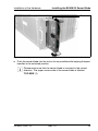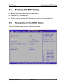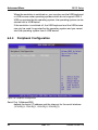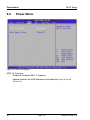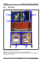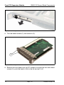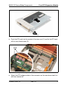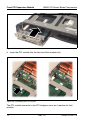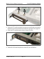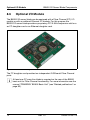
1
PRIMERGY
PRIMERGY BX620 S2
2-way Server Blade
Operating Manual
Walter Dick
Fujitsu Siemens Computers GmbH Paderborn
33094 Paderborn
e-mail: email: [email protected]
Tel.: (05251)8-14854
Fax: (++49) 700 / 372 00001
U41595-J-Z156-1-76
Sprachen: En
Edition December 2004
Comments… Suggestions… Corrections…
The User Documentation Department would like to
know your opinion of this manual. Your feedback helps
us optimize our documentation to suit your individual
needs.
Fax forms for sending us your comments are included in
the back of the manual.
There you will also find the addresses of the relevant
User Documentation Department.
Certified documentation
according to DIN EN ISO 9001:2000
To ensure a consistently high quality standard and
user-friendliness, this documentation was created to
meet the regulations of a quality management system
which complies with the requirements of the standard
DIN EN ISO 9001:2000.
cognitas. Gesellschaft für Technik-Dokumentation mbH
www.cognitas.de
Copyright and Trademarks
Copyright © 2004 Fujitsu Siemens Computers GmbH.
All rights reserved.
Delivery subject to availability; right of technical modifications reserved.
All hardware and software names used are trademarks of their respective manufacturers.
This manual is printed on
paper treated with
chlorine-free bleach.
Contents
1
1.1
1.2
1.3
1.4
Introduction . . . . . . . . . .
Overview of the Documentation
Features . . . . . . . . . . . .
Notational Conventions . . . .
Technical Data . . . . . . . . .
2
Overview: Installation Steps . . . . . . . . . . . . . . . . . . 11
3
3.1
3.2
3.3
3.4
3.5
Important Information . . . . . . . . . . . . . .
Notes On Safety . . . . . . . . . . . . . . . . . .
Components With Electrostatic-Sensitive Devices
CE Certificate . . . . . . . . . . . . . . . . . . .
FCC Class A Compliance Statement . . . . . . .
Environmental Protection . . . . . . . . . . . . .
.
.
.
.
.
.
.
.
.
.
.
.
13
13
15
15
16
17
4
4.1
4.2
4.3
4.4
4.4.1
Installation of the Hardware . . . . . . . . . . . . . . . . .
Installation Steps . . . . . . . . . . . . . . . . . . . . . . . .
Unpacking the BX620 S2 Server Blade . . . . . . . . . . . .
Installing the BX620 S2 Server Blade in the BX600 Basic Unit
Connecting the BX620 S2 Server Blade . . . . . . . . . . . .
Connecting External Devices . . . . . . . . . . . . . . . . .
.
.
.
.
.
.
19
19
19
20
25
25
5
5.1
5.2
5.3
5.4
Preparation for Use and Operation . . . . . . . . .
Operating and Connection Panel . . . . . . . . . . .
Switching a BX620 S2 Server Blade On/Off . . . . . .
Configuring a BX620 S2 Server Blade with ServerStart
Updating Firmware (BIOS and BMC) . . . . . . . . .
.
.
.
.
.
.
.
.
.
.
.
.
.
.
.
.
.
.
.
.
.
.
.
.
.
27
28
30
31
34
6
6.1
6.2
6.3
6.4
6.4.1
6.4.2
6.4.3
6.4.4
6.4.5
6.4.6
6.5
6.6
6.7
BIOS Setup . . . . . . . . .
Entering the BIOS Setup . .
Navigating in the BIOS Setup
Main Menu . . . . . . . . . .
Advanced Menu . . . . . . .
Server Management . . . . .
Console Redirection . . . . .
Advanced Chipset Feature .
Peripheral Configuration . . .
PCI Configuration . . . . . .
Server . . . . . . . . . . . .
Power Menu . . . . . . . . .
Boot Menu . . . . . . . . . .
Security Menu . . . . . . . .
.
.
.
.
.
.
.
.
.
.
.
.
.
.
.
.
.
.
.
.
.
.
.
.
.
.
.
.
.
.
.
.
.
.
.
.
.
.
.
.
.
.
.
.
.
.
.
.
.
.
.
.
.
.
.
.
.
.
.
.
.
.
.
.
.
.
.
.
.
.
35
37
37
39
40
42
44
45
46
47
48
50
51
53
U41595-J-Z156-1-76
.
.
.
.
.
.
.
.
.
.
.
.
.
.
.
.
.
.
.
.
.
.
.
.
.
.
.
.
.
.
.
.
.
Rev. 1.0
.
.
.
.
.
.
.
.
.
.
.
.
.
.
.
.
.
.
.
.
.
.
.
.
.
.
.
.
.
.
.
.
.
.
.
.
.
.
.
.
.
.
.
.
.
.
.
.
.
.
.
.
.
.
.
.
.
.
.
.
.
.
.
.
.
.
.
.
.
.
.
.
.
.
.
.
.
.
.
.
.
.
.
.
.
.
.
.
.
.
.
.
.
.
.
.
.
.
.
.
.
.
.
.
.
.
.
.
.
.
.
.
.
.
.
.
.
.
.
.
.
.
.
.
.
.
.
.
.
.
.
.
.
.
.
.
.
.
.
.
.
.
.
.
.
.
.
.
.
.
.
.
.
.
.
.
.
.
.
.
.
.
.
.
.
.
.
.
.
.
.
.
.
.
.
.
.
.
.
.
.
.
.
.
.
.
.
.
.
.
.
.
.
.
.
.
.
.
.
.
.
.
.
.
.
.
.
.
.
.
.
.
.
.
.
.
.
.
.
.
.
.
.
.
.
.
.
.
.
.
.
.
.
.
.
.
.
.
.
.
.
.
.
.
.
.
.
.
.
.
.
.
.
.
.
.
.
.
.
.
.
.
.
.
.
.
.
.
.
1
1
3
7
7
Contents
6.8
Exit Menu . . . . . . . . . . . . . . . . . . . . . . . . . . . . . 55
7
Troubleshooting and Tips . . . . . . . . . . . . . . . . . . . . 57
8
8.1
8.2
8.3
8.4
8.4.1
8.4.2
8.5
8.6
8.7
BX620 S2 Server Blade Components . . . . . .
Opening the BX620 S2 Server Blade . . . . . . . .
Overview . . . . . . . . . . . . . . . . . . . . . .
Memory . . . . . . . . . . . . . . . . . . . . . . .
Hard Disk Drives . . . . . . . . . . . . . . . . . .
Replacement of the HDD Module During Operation
Installing/Removing a Hard Disk Drive Module . . .
Front PCI Expansion Module . . . . . . . . . . . .
Optional I/O Module . . . . . . . . . . . . . . . . .
Exchanging the Battery . . . . . . . . . . . . . . .
.
.
.
.
.
.
.
.
.
.
.
.
.
.
.
.
.
.
.
.
.
.
.
.
.
.
.
.
.
.
.
.
.
.
.
.
.
.
.
.
.
.
.
.
.
.
.
.
.
.
.
.
.
.
.
.
.
.
.
.
.
.
.
.
.
.
.
.
.
.
59
59
60
61
65
66
66
68
74
78
Abbreviations . . . . . . . . . . . . . . . . . . . . . . . . . . . . . . . . 79
Related publications . . . . . . . . . . . . . . . . . . . . . . . . . . . . 83
Index
. . . . . . . . . . . . . . . . . . . . . . . . . . . . . . . . . . . . 85
Rev. 1.0
U41595-J-Z156-1-76
1
Introduction
The PRIMERGY BX620 S2 server blade is a further model of the highly
compact, powerful server blade which can be operated in the PRIMERGY
BX600 basic unit.
Figure 1: PRIMERGY BX620 S2 server blade
As ultracompact systems, the BX620 S2 server blades with one or two CPUs
are ideally suited for use in computer centers in companies and Internet service
providers. They are ideally suited to function as large application servers,
terminal servers for computer-intensive applications, and as DBMS servers.
Security functions in the BIOS Setup protect the data on the server blades
against manipulation.
The BX620 S2 server blade occupies one slot in the BX600 basic unit. It can be
integrated together with other PRIMERGY BX600 server blade models.
I Information on installation, setup and operation of the BX600 basic unit
is provided in the manual “PRIMERGY BX600 Basic Unit” (see “Related
publications” on page 83).
1.1
Overview of the Documentation
I PRIMERGY manuals are available in PDF format on the ServerBooks
CD. The ServerBooks CD is part of the PRIMERGY ServerView Suite
delivered with each server system.
U41595-J-Z156-1-76
Rev. 1.0
1
Overview of the Documentation
Introduction
The PDF files for the manuals can also be downloaded free of charge
from the Internet. The overview page showing the online documentation
available in the Internet can be found via the URL:
http://manuals.fujitsu-siemens.com/primergyservers.html.
Concept and Target Group of this Manual
This Operating Manual is intended for users who are responsible for installing
the hardware and operating the BX620 S2 server blade on the PRIMERGY
BX600 basic unit. It contains special information for installation, placing in
service and operation of the PRIMERGY BX620 S2 server blade blade.
All global information for server blade models for installation, placing in service
and operation of PRIMERGY BX600 server blades is available in the manual
“PRIMERGY BX600 basic unit” (see “Related publications” on page 83).
For a brief overview of the installation steps please see chapter 2 on page 11ff.
To understand the different expansion options, you need a knowledge of
hardware and data transmission, as well as basic knowledge of the operating
system used.
Additional Server Documentation
The PRIMERGY BX600 documentation set includes the following additional
manuals:
– “Safety” manual (print version delivered together with the system, PDF
version available on the ServerBooks CD)
– “Ergonomics” manual (PDF version available on the ServerBooks CD)
– “Warranty” manual (print version delivered together with the system, PDF
version available on the ServerBooks CD)
– “PRIMERGY BX600 Basic Unit” manual (PDF version available on the
ServerBooks CD)
– “PRIMERGY ServerView Suite – ServerStart” manual (print version
delivered together with the system, PDF version available on the ServerBooks CD)
– “PRIMERGY BX Blade Server Systems: RemoteView Management Blade User Interface Description” (PDF version available on the ServerBooks CD)
– “PRIMERGY BX Blade Server Systems: LAN Switch Blade - User Interface
Description” manual (PDF version available on the ServerBooks CD)
2
Rev. 1.0
U41595-J-Z156-1-76
Introduction
Features
Further Sources of Information
Further information is provided in:
–
–
–
–
–
–
–
the RemoteDeploy manual (only relevant for cloning server blades)
the technical manual for the rack
the manual for the monitor
the ServerView Server Management manual
the manual for the Remote Test and Diagnostic System RemoteView
your operating system documentation
the information files of your operating system
(see also “Related publications” on page 83).
1.2
Features
CPU
One or two Intel® XEON® processors with 3.0 GHz to 3.6 GHz and 1 MB
second-level cache ensure high data throughput and system performance.
V CAUTION!
Only CPUs with the same clock frequency and cache capacity can be
combined in a BX620 S2 server blade.
Memory
There are three memory banks, each with two slots available on the
BX620 S2 server blade. These can be fitted with 1 GB, 2 GB or 4 GB DDR2 400
memory. The maximum memory expansion is 12 GB. ECC with memory
scrubbing function, ChipKill™ and hot-spare memory bank are standard.
I Only x4-based DRAM organization and single rank SDRAM modules are
supported on the BX620 S2 server blade.
SCSI Hard Disk Drives
The BX620 S2 server blade can accommodate two 3.5“ SCA2 SCSI hard disk
drives (HDD) with 36, 73, 146 or 146 GB (10,000 rpm) or 18, 36, 73 GB
(15,000 rpm). The maximum hard disk capacity on one BX620 S2 server blade
is 292 (2x146) GB in a RAID 0 configuration. Usually the two disks are mirrored
in a RAID 1 configuration. Each BX620 S2 server blade is equipped with a twochannel Ultra 320 SCSI onboard controller and embedded HostRAID.
U41595-J-Z156-1-76
Rev. 1.0
3
Features
Introduction
I Only one SCSI HDD module can be installed if a PCI expansion module
is installed.
LAN Availability
The BX620 S2 server blade has four Gigabit LAN channels. Usually two
channels are connected with the switch blades. Each switch blade has ten
1-Gigabit downlink ports to connect the server blades and three uplink ports for
10/100/1000 Base TX.
Graphics Controller
The BX620 S2 server blade is fitted with an on-board graphics controller ATI
Radeon 7000-M with 16 MB.
Optional Fibre Channel or Ethernet I/O Module
The BX620 S2 server blade has an proprietary PCI expansion slot for installing
either a Fibre Channel I/O module for SAN environment or an additional Gigabit
Ethernet Controller (see section “Optional I/O Module” on page 74).
To use Fibre Channel functionality or the additional Ethernet channels, at least
one Fibre Channel pass-thru blade or at least one Gigabit Ethernet pass-thru
blade respectively is also required in the BX600 basic unit.
Optional Front PCI Expansion Module
The BX620 S2 server blade can be equipped with an external PCI expansion
slot instead of a SCSI HDD module slot for installing an addition SCSI controller
or an additional Ethernet controller (see section “Front PCI Expansion Module”
on page 68) .
High Level of Availability and Failure Protection
When memory data is accessed, 1-bit errors in the main memory are recognized and automatically corrected with the ECC (Error Correcting Code)
method.
ASR&R (Automatic Server Reconfiguration and Restart) restarts the system in
the case of an error and automatically “hides” the defective system components.
The PDA (Prefailure Detection and Analyzing) technology from Fujitsu Siemens
Computers analyzes and monitors all components relevant for system reliability.
4
Rev. 1.0
U41595-J-Z156-1-76
Introduction
Features
The on-board SCSI-RAID controllers with HostRAID support (RAID-Levels 0
and 1) increase system availability.
Server Management
Server management is implemented via the supplied ServerView software and
PDA (Prefailure Detection and Analyzing) technology from Fujitsu Siemens
Computers. PDA warns of system errors or overloading before they occur so
that preventive measures can be taken.
ServerView allows the management of all PRIMERGY servers in the network via
a central console. Here ServerView supports the following functions:
●
Temperature monitoring of the CPU and the surrounding area
●
Watchdog timer for Automatic Server Reconfiguration and Restart (ASR&R)
in the event of memory modules or processors failing
●
Power monitoring
●
End-of-life monitoring of the fans with timely notification before a failure
●
Watchdog timer for operating system monitoring and application monitoring
with ASR&R
Deployment software makes installing multiple servers fast and easy. For
further information, see the corresponding documentation (see “Related publications” on page 83).
Information on server management with ServerView is provided in the associated
documentation (see also “Related publications” on page 83).
ServerStart
You can configure the server quickly and precisely with the ServerStart software
provided. User-guided menus are available for installing the server operating
systems.
Service and Support
PRIMERGY servers are service-friendly and modular, thus allowing quick and
easy maintenance.
I For easy and immediate recognition, the levers or handles and locking
buttons (touch points) of the locking mechanisms for the different components have the color green.
U41595-J-Z156-1-76
Rev. 1.0
5
Features
Introduction
The flash EPROM program supplied with the Fujitsu Siemens utilities supports
fast BIOS update. The two redundant and hot-swappable management blades
with independent management LAN and COM ports ensure complete remote
control. Together they facilitate remote diagnosis for system analysis, remote
configuration, and remote restart should the operating system or hardware fail.
6
Rev. 1.0
U41595-J-Z156-1-76
Introduction
1.3
Notational Conventions
Notational Conventions
The following notational conventions are used in this manual:
Italics
indicate commands, menu items or software programs.
“Quotation marks”
indicate names of chapters and terms that should be
emphasized.
Ê
Text which follows this symbol describes activities that
must be performed in the order given.
V CAUTION!
I
Pay particular attention to text marked with this symbol.
Failure to observe this warning may endanger your life,
damage the server, or lead to loss of data.
This symbol introduces supplementary information,
remarks and tips.
Table 1: Notational conventions
1.4
Technical Data
Compliance Standards
Product safety and ergonomics IEC 60950 / EN 60950 UL 1950 3rd Edition,
CSA 22.2 No. 950
Electromagnetic compatibility
Emitted interference
FCC class A
EN 55022 class A
Harmonic current
EN 61000-3-2
Noise immunity
EN 55024
CE label
according to EU directives
U41595-J-Z156-1-76
Low-Voltage Directive 73/23/EEC
Electromagnetic Compatibility 89/336/EEC
Rev. 1.0
7
Technical Data
Introduction
Approvals
Product safety
Global
CB
Europe
ENEC
Germany
GS
USA/Canada
CSAUS / CSAC
Japan
VCCI
Mechanical Values
Width
286 mm
Space requirement
470 mm (520 mm incl. levers and connectors)
Height
43 mm (1 slot in the BX600 basic unit)
Weight
Max. 7.3 kg (dependent on configuration)
Environmental Conditions
Environment class 3K2
Environment class 2K2
DIN IEC 721 section 3-3
DIN IEC 721 section 3-2
Temperature:
Operation (3K2)
Transport (2K2)
Relative humidity
5 °C .... 35 °C
-20 °C .... 60 °C
10%...85%
Condensation during operation must be avoided.
Power requirements and heat dissipation
Power requirements
~ 300 W (fully equipped)
Heat dissipation
Min. ~ 750 kJ/h,
Max. ~ 1000 kJ/h
8
Rev. 1.0
U41595-J-Z156-1-76
Introduction
Technical Data
Noise Level
I This data refers to the BX600 basic unit.
Sound power level LWAd (ISO 7779)
7.8 BA
Sound pressure level at bystander position
LpAm (ISO 9296)
≤ 59 dB(A) (in the
standard configuration
U41595-J-Z156-1-76
Rev. 1.0
9
2
Overview: Installation Steps
This chapter contains an overview of the steps required to install your
BX620 S2 server blade in the PRIMERGY BX600 basic unit. Links will connect
you to the sections with detailed descriptions of the individual steps.
I The information required for installing and placing in service the
PRIMERGY BX600 basic unit can be found in the manual “PRIMERGY
BX600 Basic Unit - Operating Manual” (see “Related publications” on
page 83).
Ê First of all read the chapter “Important Information” as of page 13, especially
the section “Notes On Safety”.
Ê Unpack the BX620 S2 server blade, check the package contents for visible
transport damage, and for whether the delivery corresponds to the details on
the delivery note (see section 4.2 on page 19).
Ê Familiarize yourself with the controls and indicator elements on the front of
the BX620 S2 server blade (see chapter 5 as of page 27).
Ê Install the desired operating systems and applications on the server blades.
To do so, you have the following options:
– Cloning a server blade from a remote image server with RemoteDeploy
Recommended if the following requirements are satisfied:
– the RemoteDeploy software is available
– an appropriate cloning image is available
– deployment server and LAN connection are available
– Remote installation with ServerStart
This installation method is recommended if a LAN connection and a
DHCP server (deployment server) are available but the requirements for
cloning are not satisfied.
U41595-J-Z156-1-76
Rev. 1.0
11
Overview: Installation Steps
– Local installation with or without ServerStart
Since the local installation is the least convenient installation method, it
is only recommended if the requirements for remote installation or
cloning are not satisfied.
If you wish to install an operating system that is not supported by ServerStart, you can perform the installation directly without using ServerStart.
I For further information on remote or local installation of server blades,
please see the ServerStart manual, which contains a “Quick Step
Guide” as well as a detailed description of the different installation
options and installation wizards. A print version of the ServerStart
manual is included in the PRIMERGY ServerView Suite, delivered
with the BX600 basic unit. A PDF version of the manual is contained
on the PRIMERGY ServerBooks CD.
Cloning of server blades is described in the RemoteDeploy manual
(print version delivered with RemoteDeploy, PDF version contained
on the PRIMERGY ServerBooks CD).
12
Rev. 1.0
U41595-J-Z156-1-76
3
Important Information
This chapter contains safety information which you must always observe when
using your BX620 S2 server blade.
3.1
Notes On Safety
I You will also find the following safety instructions in the manual entitled
“Safety“, which also includes additional notes on the guarantee and
ergonomics.
This device complies with the relevant safety regulations for data processing
equipment, including electronic office machines for use in an office
environment.
If you have any questions, please contact your sales outlet or the customer
service center of Fujitsu Siemens Computers.
V CAUTION!
The actions described in these instructions should only be performed by
technicians, service personnel or technical specialists. Equipment
repairs should only be performed by qualified staff. Any failure to observe
the guidelines in this manual could expose the user to risks (electric
shock, fire hazards) and could also damage the equipment. Note that
any unauthorized opening of the device will result in the invalidation of
the warranty and exclusion from all liability.
Before Setting Up
V CAUTION!
●
During installation and before operating the device, observe the
instructions on environmental conditions for your device in the section
“Technical Data” on page 7.
●
If the device is brought in from a cold environment, condensation may
form on both the inside and outside of the machine.
Before operating the device, wait until it is absolutely dry and has
reached approximately the same temperature as the installation site.
Failure to observe these guidelines can lead to physical damage of
the device.
U41595-J-Z156-1-76
Rev. 1.0
13
Notes On Safety
Important Information
V CAUTION!
●
Transport the device only in the original packaging or in packaging
which protects it from knocks and jolts.
Setup and Operation
V CAUTION!
●
Observe the information for setting up your system and operating it in
the manual “PRIMERGY BX600 Basic Unit” (see “Related publications” on page 83).
Batteries
V CAUTION!
●
Incorrect replacement of batteries may lead to a risk of explosion. The
battery may only be replaced with an identical battery or with a type
recommended by the manufacturer.
●
Do not throw batteries into the trash can. They must be disposed of
in accordance with local regulations concerning special waste.
●
Replace the lithium battery on the relevant components according to
the instructions in this manual.
●
All batteries containing pollutants are marked with a symbol (a
crossed-out garbage can) as well as the chemical symbol for the
heavy metal which classifies it as a pollutant:
Cd Cadmium
Hg Mercury
Pb Lead
Other Important Notes:
●
14
Keep this operating manual and all additional documentation together with
the device.
If you pass on the device to third parties, you should also pass on the
complete documentation.
Rev. 1.0
U41595-J-Z156-1-76
Important Information
3.2
Components With Electrostatic-Sensitive Devices
Components With Electrostatic-Sensitive
Devices
Electrostatic-sensitive components are identified by the following sticker:
Figure 2: ESD label
When you handle components fitted with ESDs, you must observe the following
points under all circumstances:
●
Always discharge static build-up (e.g. by touching a grounded object) before
working.
●
The equipment and tools you use must be free of static charge.
●
Always hold components with ESDs by their edges.
●
Do not touch any exposed pins or conductors on a component.
●
Use a grounding cable designed for this purpose to connect yourself to the
system unit as you install components.
●
Place all components on a static-proof base.
I You will find a detailed description of how to handle ESD components in
the relevant European or international standards (EN 61340-5-1,
ANSI/ESD S20.20).
3.3
CE Certificate
The shipped version of this device complies with the requirements
of the EEC directives 89/336/EEC “Electromagnetic compatibility”
and 73/23/EEC “Low voltage directive”. The device therefore
qualifies for the CE certificate (CE=Communauté Européenne).
U41595-J-Z156-1-76
Rev. 1.0
15
FCC Class A Compliance Statement
3.4
Important Information
FCC Class A Compliance Statement
If there is an FCC statement on the device, then:
The following statement applies to the products covered in this manual, unless
otherwise specified herein. The statement for other products will appear in the
accompanying documentation.
NOTE:
This equipment has been tested and found to comply with the limits for a
“Class A” digital device, pursuant to Part 15 of the FCC rules, and meets all
requirements of the Canadian Interference-Causing Equipment Standard
ICES-003 for digital apparatus. These limits are designed to provide reasonable
protection against harmful interference in a residential installation. This
equipment generates, uses and can radiate radio frequency energy and, if not
installed and used in strict accordance with the instructions, may cause harmful
interference to radio communications. However, there is no guarantee that
interference will not occur in a particular installation. If this equipment does
cause harmful interference to radio or television reception, which can be determined by turning the equipment off and on, the user is encouraged to try to
correct the interference by one or more of the following measures:
●
Reorient or relocate the receiving antenna.
●
Increase the separation between equipment and the receiver.
●
Connect the equipment to an outlet on a circuit different from that to which
the receiver is connected.
●
Consult the dealer or an experienced radio/TV technician for help.
Fujitsu Siemens Computers is not responsible for any radio or television interference caused by unauthorized modifications of this equipment or the substitution or attachment of connecting cables and equipment other than those
specified by Fujitsu Siemens Computers. The correction of interferences
caused by such unauthorized modification, substitution or attachment will be the
responsibility of the user.
The use of shielded I/O cables is required when connecting this equipment to
any and all optional peripheral or host devices. Failure to do so may violate FCC
and ICES rules.
16
Rev. 1.0
U41595-J-Z156-1-76
Important Information
3.5
Environmental Protection
Environmental Protection
Environmentally Friendly Product Design and Development
This product has been designed in accordance with standards for “environmentally friendly product design and development”. This means that the designers
have taken into account important criteria such as durability, selection of
materials and coding, emissions, packaging, the ease with which the product
can be dismantled and the extent to which it can be recycled.
This saves resources and thus reduces damage to the environment.
Notes On Saving Energy
Devices that do not have to be on permanently should not be switched on until
they need to be used and should be switched off during long breaks and on
completion of work.
Notes On Packaging
Please do not throw away the packaging. We recommend that you keep the
original packaging in case you need it later for transporting your system unit. If
possible, devices should be transported in their original packaging.
Notes On Dealing With Consumables
Please dispose of printer consumables and batteries in accordance with local
government regulations.
Do not throw lithium batteries into the household waste. They must be disposed
of in accordance with local regulations on special waste.
Notes On Labeling Plastic Housing Parts
Please avoid attaching your own labels to plastic housing parts wherever
possible, since this makes it difficult to recycle them.
U41595-J-Z156-1-76
Rev. 1.0
17
Environmental Protection
Important Information
Take-back, Recycling and Disposal
For details on take-back and reuse of devices and consumables within Europe,
contact your Fujitsu Siemens Computers branch office/subsidiary or our
recycling center in Paderborn, Germany:
Fujitsu Siemens Computers
Recycling Center
D-33106 Paderborn
Tel.:
+49 5251 8 18010
Fax:
+49 5251 8 18015
18
Rev. 1.0
U41595-J-Z156-1-76
4
Installation of the Hardware
V CAUTION!
Observe the safety information in the chapter “Important Information” on
page 13.
The BX620 S2 server blade should not be exposed to any extreme
ambient conditions (see the section “Technical Data” on page 7). Protect
it from dust, moisture and heat.
4.1
Installation Steps
The following installation steps are described in detail in this chapter:
●
Unpacking the system (4.2 on page 19).
●
Installing the BX620 S2 server blade in the BX600 basic unit (see 4.3 on
page 20).
●
Connecting the BX620 S2 server blade (see 4.4 on page 25).
4.2
Unpacking the BX620 S2 Server Blade
V CAUTION!
Observe the safety information in the chapter “Important Information”
starting on page 13.
Only unpack the BX620 S2 server blade where you want to install it.
You should keep the original packaging of the server system in case you need
to transport it again.
Ê Unpack all parts.
Ê Check the contents of the package for visible transport damage.
Ê Check whether the delivery matches the details on the delivery note.
The type rating plate is located on the front right-hand side of the
BX620 S2 server blade’s cover.
If you recognize transport damage or differences between the contents of the
package and the delivery note, please inform your supplier immediately!
U41595-J-Z156-1-76
Rev. 1.0
19
Installing the BX620 S2 Server Blade
4.3
Installation of the Hardware
Installing the BX620 S2 Server Blade in the
BX600 Basic Unit
A 4-way server blade occupies one slot in the BX600 basic unit. In all you can
install five BX620 S2 server blades in a PRIMERGY BX600 basic unit. Different
server blade models can also be operated together in a BX600 basic unit.
Detailed information on the configuration options is provided in the manual
“PRIMERGY BX600 Basic Unit” (see “Related publications” on page 83).
V CAUTION!
Read the safety information and the information on handling electrostatic-sensitive components in the section “Components With Electrostatic-Sensitive Devices” on page 15.
Removing the Dummy Module
All unoccupied slots in the BX600 basic unit are fitted with dummy modules to
ensure that the electromagnetic emission properties of the system are observed
and that the system components are properly cooled.
If you want to add a BX620 S2 server blade, you must first remove a dummy
module from the corresponding slot.
20
Rev. 1.0
U41595-J-Z156-1-76
Installation of the Hardware
1
Installing the BX620 S2 Server Blade
2
3
Figure 3: Removing a server blade dummy module
Ê Release the locking mechanism of the ejecting handles by pressing the
touch points on the inside of both handles (1) simultaneously. The ejecting
handles of the dummy module will be disengaged.
Ê Swing up the upper handle and swing down the lower handle simultaneously
(2) until the locking mechanism of the dummy module disengages and the
dummy module ejects.
Ê Remove the dummy module completely from the slot (3).
V CAUTION!
Keep the dummy module for future use. If the BX620 S2 server blade is
removed and not replaced with a new server blade, then the dummy
module must be reinstalled for cooling, to comply with the applicable
EMC regulations (regulations on electromagnetic compatibility) and for
fire protection.
Installation is the same as for the server blade (see “Installing a
BX620 S2 Server Blade” on page 22).
U41595-J-Z156-1-76
Rev. 1.0
21
Installing the BX620 S2 Server Blade
Installation of the Hardware
Installing a BX620 S2 Server Blade
V CAUTION!
Read the safety information and the information on handling electrostatic-sensitive components in the section “Components With Electrostatic-Sensitive Devices” on page 15.
2
2
1
1
Figure 4: Turning the eject handles into the unlocked position
Ê Press the touch points on the inside of the eject handles (1) of the
BX620 S2 server blade to disengage the locking mechanism of the handles.
Ê Turn the eject handles outward (2) into the unlocked position.
22
Rev. 1.0
U41595-J-Z156-1-76
Installation of the Hardware
Installing the BX620 S2 Server Blade
1
Figure 5: Installing a server blade
Ê Push the server blade into the slot as far as possible while keeping the eject
handles in the unlocked position.
I Please make sure that the server blade is mounted in the correct
direction. The upper narrow side of the server blade is labeled
TOP-SIDE (1).
U41595-J-Z156-1-76
Rev. 1.0
23
Installing the BX620 S2 Server Blade
Installation of the Hardware
Figure 6: Final engaging of the locking mechanism
Ê Press the eject handles to enable the locking mechanism to engage fully.
Removing the BX620 S2 Server Blade
The BX620 S2 server blade is removed in the same way as the dummy module
(see “Removing the Dummy Module” on page 20).
V CAUTION!
Read the safety information and the information on handling electrostatic-sensitive components in the section “Components With Electrostatic-Sensitive Devices” on page 15.
When you remove the BX620 S2 server blade and do not replace it with a new
one, you must insert a dummy module in the empty slot. Make sure that the
dummy module engages in the slot correctly.
24
Rev. 1.0
U41595-J-Z156-1-76
Installation of the Hardware
4.4
Connecting a 4-way server blade
Connecting the BX620 S2 Server Blade
All connections required for operating the BX620 S2 server blade are made via
the midplane of the BX600 basic unit. When the BX620 S2 server blade is
installed in the BX600 basic unit, plug contacts to the midplane automatically set
up contacts to the following modules on the rear of the BX600 basic unit:
– Power supply units for the power supply
– Management blade(s) for server administration
– KVM blade for connecting monitor, keyboard and mouse
– Switch blade(s) for connecting to the LAN
– Fibre Channel pass-thru blade or Ethernet pass-thru blade for implementing
a Fibre Channel port or an additional Ethernet port (optional, calls for the
installation of a Fibre Channel or Gigabit Ethernet daughter card in the
server blade, see the section “Optional I/O Module” on page 74)
– SCSI blade for connecting an external SCSI device (only available for server
blade slots 4 and 10 of the BX600 basic unit, see the manual “PRIMERGY
BX600 Basic Unit”)
4.4.1
Connecting External Devices
The BX620 S2 server blade has a USB/VGA connector (1) at the front.
1
Figure 7: USB/VGA connector on the 4-way server blade
U41595-J-Z156-1-76
Rev. 1.0
25
Connecting a 4-way server blade
Installation of the Hardware
For connection to an external device via the USB/VGA connector of the
BX620 S2 server blade you require a special cable (see figure 8).
Figure 8: USB/VGA cable
I The USB/VGA cable is part of the delivery scope of the PRIMERGY
BX600 basic unit.
Information on connecting external devices via the infrastructure module
of the PRIMERGY BX600 basic unit is provided in the manual
“PRIMERGY BX600 Basic Unit” (see “Related publications” on page 83).
26
Rev. 1.0
U41595-J-Z156-1-76
5
Preparation for Use and
Operation
V CAUTION!
Observe the safety information in the chapter “Important Information” on
page 13.
This chapter contains the information which is required for placing in service
and operating the BX620 S2 server blade after it has been installed in the
PRIMERGY BX600 basic unit.
– Position and meaning of the elements in the operating and connection panel
of the BX620 S2 server blade are explained in section 5.1 on page 28.
– Section 5.2 on page 30 provides details on the various options for switching
the BX620 S2 server blade on and off.
– In section 5.3 on page 31 you will find information on configuring the 2-way
server bade with ServerStart.
– Section 5.4 on page 34 contains information on updating the firmware of the
BX620 S2 server blade.
U41595-J-Z156-1-76
Rev. 1.0
27
Operating and Connection Panel
5.1
Preparation for Use and Operation
Operating and Connection Panel
1
2
3
4
5
6
7
8
9
Figure 9: BX620 S2 server blade: Operating panel
The following operating, indicator and connection elements are provided
(figure 9 on page 28):
1
Power button fully compatible with Advanced Configuration Power
Interface (ACPI)
When the BX600 basic unit is switched on (5 V standby power is
present) and the server blade is switched OFF and you press the power
button, a power_up command is sent to the management blade and the
server blade will be switched ON.
When the server blade is switched ON and the power button is kept
pressed for less than 4 seconds, the server blade will be switched OFF
and a power_off notification command will be sent to the management
blade (graceful shutdown).
When the server blade is switched ON and the power button is kept
pressed for more than 4 seconds, the server blade will be switched
OFF.
28
Rev. 1.0
U41595-J-Z156-1-76
Preparation for Use and Operation
2
Operating and Connection Panel
KVM (keyboard/video/mouse) button
Pressing the KVM button switches the KVM to this server blade.
3
Power/Select indicator (bicolor LED)
Dark:
The BX600 basic unit is switched OFF, no 5 V standby
power is present or this server blade is not correctly
inserted.
Lights green: Server blade is switched ON.
Lights amber: Server blade is switched OFF; 5 V standby power is
present.
Blinks green: Server blade is switched ON and has been selected for
identification or remote administration or this blade has
failed.
Blinks amber: Server blade is switched OFF and has been selected for
identification or remote administration or this blade has
failed.
Blinks green- Server blade is in standby mode (ACPI function) or this
amber:
blade is failed
Blinks green- Server blade is in standby mode (ACPI function) and
dark-amber: has been selected for identification or this blade has
failed.
4
KVM/MP fail indicator (bicolor LED)
Dark:
KVM is not selected from this server blade.
Lights green: KVM is selected from this server blade.
Blinks amber: KVM is not selected from this server blade and this
blade is disabled due to power budget.
Blinks green- KVM is selected from this server blade and this blade is
amber
disabled due to power budget.
5
I/O status of the optional I/O module (green LED)
Dark:
System is switched OFF or loss of signal synchronization
Green:
System is switched ON and online
U41595-J-Z156-1-76
Rev. 1.0
29
Switching the Server Blade On/Off
6
Preparation for Use and Operation
NIC indicator (green LED)
Dark:
System or server blade is switched OFF and LAN
interface not working.
Lights green: LAN is connected.
Blinks green: LAN is active.
7
USB/VGA connector
Adapter connector for two USB ports for external CD/FD drives and one
VGA port.
I A special cable is required! (see figure 8 on page 26)
8
HDD access (green LED)
Dark:
Hard disk drive is inactive.
Lights green: Hard disk drive is active.
9
HDD indicator (amber LED)
Lights amber: The server blade is switched ON and the hard disk drive
is faulty.
5.2
Switching a BX620 S2 Server Blade On/Off
V CAUTION!
If you switch the BX620 S2 server blade on and only flickering stripes
appear on the connected monitor, switch it off immediately (see the
chapter “Troubleshooting and Tips” on page 57).
This section describes how you can switch the BX620 S2 server blade on and
off using the operating panel of the server blade when the BX600 basic unit is
activated.
In addition, the PRIMERGY BX600 basic unit offers the option of switching the
installed server blade on and off via the operating panel of the overall system
and via the web interface of the management blade. Detailed information on this
topic is provided in the manual “PRIMERGY BX600 Basic Unit” (see “Related
publications” on page 83).
30
Rev. 1.0
U41595-J-Z156-1-76
Configuring the BX620 S2 Server Blade Switching the Server Blade On/Off
Switching the BX620 S2 Server Blade On/Off Using the Operating Panel
The BX600 basic unit must be switched on.
The server blade can be switched on and off as follows:
– To switch on the server blade, press the on/off button the server blade (item
1 in figure 9 on page 28).
To switch off the server blade, press the on/off button of the server blade
(item 1 in figure 9 on page 28) for 4 seconds.
– Defined power-on/power-off time
The server blade is switched on and off at the time defined in ServerView.
– After power failure
An activated server blade switches itself on again automatically after a
power failure (dependent on the BIOS setting, see manual “BIOS Setup”).
5.3
Configuring a BX620 S2 Server Blade with
ServerStart
PRIMERGY BX600 server blades can be configured in different ways:
– Local installation with or without ServerStart.
– For remote installation see the section ServerStart Remote Installation in the
ServerStart manual on the ServerBooks CD.
– Copying of the clone images from a remote image repository to the required
server blades (further information is provided in the manual on RemoteDeploy
on the ServerBooks CD (as of Version 5.210)).
I The optional RemoteDeploy software package is available from the
customer support of Fujitsu Siemens under the order number
U15000-C180.
U41595-J-Z156-1-76
Rev. 1.0
31
Switching the Server Blade On/Off Configuring the BX620 S2 Server Blade
Reference Installation
A reference installation of a server blade with the aid of ServerStart serves as a
basis for a clone image. The image is created and then used by RemoteDeploy
for quick installation and configuration of further server blades.
I Details on using ServerStart can be found in the Operating Manual for
ServerStart which is contained in the ServerStart bundle and on the
PRIMERGY ServerBooks CD.
Hardware Preparation
To implement initial installation of a BX620 S2 server blade or perform subsequent modifications, the relevant server blade must be connected to a CD-ROM
drive and a diskette drive via the USB/VGA interface (see the section
“Connecting External Devices” on page 25). In addition, a monitor, a keyboard
and a mouse must be connected to KVM blade on the rear of the BX600 basic
unit, and the relevant server blade must be switched to by pressing the KVM
button.
Connecting a CD-ROM drive and diskette drive to the server blade via USB
Ê Connect the breakout cable to the front USB/VGA port of the relevant server
blade (figure 7 on page 25).
Ê Connect the data cable of the CD-ROM drive and of the diskette drive to the
USB port of the breakout cable (see figure 8 on page 26).
Ê Make sure that the BX600 basic unit is switched on.
Ê Press the on/off button on the control panel to switch the server blade on
(item 1 in figure 9 on page 28.)
Ê If the CD-ROM drive and the diskette drive are not to be supplied with power
via the USB hub of the breakout cable, connect them directly to a power
outlet.
Ê Connect the monitor, keyboard and mouse to the KVM blade on the rear of
the BX600 basic unit. Information on this is provided in the manual
“PRIMERGY BX600 Basic Unit” (see “Related publications” on page 83).
Ê Press the KVM button (item 2 in figure 9 on page 28) on the server blade’s
operating panel to switch the keyboard, mouse and monitor from the KVM
blade to the server blade.
32
Rev. 1.0
U41595-J-Z156-1-76
Configuring the BX620 S2 Server Blade Switching the Server Blade On/Off
Software Preparation
Booting from the CD-ROM drive
Boot the relevant server blade from the ServerStart CD to install the operating
system. In some cases you will have to change some settings to do this:
Ê Insert the ServerStart CD in the CD-ROM drive and press the on/off button
(item 1 in figure 9 on page 28) on the server blade’s operating panel.
Ê Press the KVM button (item 2 in figure 9 on page 28) on the server blade’s
operating panel to switch the keyboard, mouse and monitor from the KVM
blade to the server blade. Wait a few seconds until the monitor has been
activated.
Ê If requested, press [F2] to call the BIOS setup of the server blade.
Ê In the BIOS Setup menu select the submenu Boot and activate Boot from CDROM Drive.
Ê Press [ESC] twice and select Exit Saving Changes from the Exit menu.
After the server blade has been booted from the ServerStart CD the startup
screen is displayed.
U41595-J-Z156-1-76
Rev. 1.0
33
Updating Firmware (BIOS and BMC)
5.4
Preparation for Use and Operation
Updating Firmware (BIOS and BMC)
All files required for updating the PRIMERGY BX600 basic unit components are
available from http://download.fujitsu-siemens.com.
You can update both the firmware of the server blade BIOS and the firmware of
the server blade BMC.
I BMC is the abbreviation for Baseboard Management Controller. The
BMC on the server blade collects management information and forwards
it to the management blade.
Two procedures are available for updating the firmware of the server blade
BIOS and of the server blade BMC:
– Updating the server blade’s firmware with TFTP
The description of this procedure is provided in the manual “PRIMERGY
BX600 Basic Unit” (see “Related publications” on page 83).
– Updating the server blade’s firmware from the USB diskette drive
Proceed as follows to update the firmware of the BX620 S2 server blade from
the USB diskette drive:
Ê Create a boot diskette and copy the required BIOS and/or BMC files to this
diskette.
Ê Connect the breakout cable to the relevant server blade. Connect the USB
diskette drive to the other end of the breakout cable.
Ê Switch the server blade on and reboot it. The firmware update takes place
automatically.
I You may have to change the order of the boot devices in the BIOS to
activate the boot from diskette. Further information on this is provided
in the manual “BIOS Setup” and in the User Guide on ServerStart.
This manual is available on the ServerBooks CD (as of Version
5.208).
34
Rev. 1.0
U41595-J-Z156-1-76
6
BIOS Setup
In the BIOS setup you can set up the system functions and the hardware configuration of a server blade.
I The scope of the displayed BIOS parameters may depend on the configuration.
On delivery, the default settings of the server blade are active. You can change
these settings in the BIOS setup. The changes will become effective when you
save them and exit the BIOS setup.
The following overview shows the structure of the BIOS Setup menu. The
numbers in square brackets refer to the pages with the relevant descriptions.
Main – Basic system configuration
BIOS Version [ 39]
BMC F/W Version [ 39]
System Time / System Date [ 39]
Sync RTC with Mgmt. Blade [ 40]
System Memory [ 40]
Memory Test [ 40]
Advanced – Advanced system configuration
Multiprocessor Specification [ 40]
Reset Configuration Data [ 41]
Quiet Boot [ 41]
Hyper-Threading Function [ 41]
Server Management [ 42]
OS Boot Watchdog Timer [ 42]
Timer Count Down Value [ 43]
Timer Count Action [ 43]
Boot Retry Counter [ 43]
ASR&R Boot Delay (Minute) [ 43]
Console Redirection [ 44]
Com Port Address [ 44]
Console Type [ 44]
Flow Control [ 44]
Post-Boot support [ 44]
Advanced Chipset Feature [ 45]
U41595-J-Z156-1-76
Rev. 1.0
35
BIOS Setup
USB Function [ 45]
USB 2.0 Controller [ 45]
Legacy USB Support [ 45]
Peripheral Configuration [ 46]
Serial Port 1(Address/IRQ) [ 46]
PCI Configuration [ 47]
Server [ 48]
Memory Scrubbing [ 48]
Memory Spare [ 49]
DIMM x,y [ 49]
CPUx Status [ 49]
Power – Power management
APM 1.2 Interface [ 50]
After Power Failure [ 51]
Boot – System start
Boot Device Priority [ 52]
Hard Disk Drives [ 52]
Removable Drives [ 52]
CD/DVD Drives [ 52]
Security – Security functions
Supervisor Password / User Password [ 53]
Change Supervisor Password [ 53]
Change User Password [ 53]
Password Check [ 54]
Password Check [ 54]
Exit – Save settings and quit BIOS setup
Save Changes and Exit [ 55]
Discard Changes and Exit [ 55]
Discard Changes [ 55]
Load Optimal Defaults [ 55]
The following sections describe how to enter and navigate in the BIOS setup as
well as the individual menus and possible settings.
36
Rev. 1.0
U41595-J-Z156-1-76
BIOS Setup
6.1
Entering the BIOS Setup
Entering the BIOS Setup
Ê Restart the server blade (cold or warm start).
Ê Press the [F2] function key.
Ê Enter the setup password (if defined) and confirm by pressing Enter.
6.2
Navigating in the BIOS Setup
The BIOS setup screen has the following structure:
Figure 10: Structure of the BIOS setup screen
U41595-J-Z156-1-76
Rev. 1.0
37
Navigating in the BIOS Setup
BIOS Setup
Menu bar
Use the À and  keys to select a menu (Main, Advanced, ...) from the
menu bar.
Work area
The work area (left part of the screen) shows the menu information and
possible settings for the selected menu. Use the Êand Ë cursor keys
to select the menu item you want.
A [Ê] on the left indicates a menu item which contains submenus. To
open a submenu select the corresponding menu item and press Enter.
Pressing the [ESC] key in the submenu returns you to the higher menu.
Square brackets ([ ]) enclosing a parameter value show that this value
can be changed by pressing the [+] and [-] keys. If the parameter
consists of several input sections, as is the case with the time or date,
you reach the next section by pressing the [Tab] key.
An asterisk in front of a menu item indicates configuration conflicts that
must be solved.
Information area
The information area (right part of the screen) contains brief information
on the selected menu item and on using the BIOS setup.
38
Rev. 1.0
U41595-J-Z156-1-76
BIOS Setup
6.3
Main Menu
Main Menu
Figure 11: Main menu
BIOS Version
indicates the BIOS version.
BMC F/W Version
indicates the firmware version of the baseboard management controller
(BMC).
System Time / System Date
used to set the system date and time.
The system time has the format HH:MM:SS. The system date has the
format weekday MM/DD/YYYY. Use the tab key to position the cursor
within the individual input fields.
I If the system shows the wrong system date and time after switchon and switch-off, the lithium battery has run out and must be
replaced.
U41595-J-Z156-1-76
Rev. 1.0
39
Advanced Menu
BIOS Setup
Sync RTC with Mgmt. Blade
switches synchronization of the real-time clock and the time of the
management blade on (Enabled) or off (Disabled).
System Memory
indicates the size of the available main memory.
Memory Test
defines whether a memory test is performed during BIOS startup
(Enabled) or not (Disabled).
6.4
Advanced Menu
Figure 12: Advanced menu
Multiprocessor Specification
sets the multiprocessor table version to be used.
I For compatibility reasons some operating systems require version
1.1.
40
Rev. 1.0
U41595-J-Z156-1-76
BIOS Setup
Advanced Menu
Reset Configuration Data
defines whether the configuration data is reinitialized when the server
blade is started.
Yes
When the server blade is started, the plug&play functionality
detects the new configuration data and uses it to initialize the
installed boards and drives. The field is set to No.
No
When the server blade is started, the plug&play functionality
initializes the installed boards and drives with the configuration
data that is currently in effect.
Quiet Boot
defines whether a logo (Enabled) is displayed on the screen instead of the
startup information (Disabled). This function can only be set if the Console
Redirection function (see further down) is switched off.
If you have selected the logo display, you can switch to the startup information by pressing [F3] or [ESC]. In the case of an error, the startup
information is displayed automatically.
Hyper-Threading Function
defines whether the operating system can use all the logical processors
within a physical processor (Enabled) or only the first logical processor
(Disabled).
I The hyper-threading technology makes a single physical
processor appear as multiple logical processors, which allows the
operating system to make better use of the internal processor
resources. The advantages of this technology can only be used by
operating systems with hyper-threading support. This setting has
no effect on operating systems which do not support hyperthreading.
Server Management
opens a submenu for setting restart options (see section “Server
Management” on page 42).
Console Redirection
opens a submenu for setting terminal communication options (see
section “Console Redirection” on page 44).
Advanced Chipset Feature
opens a submenu for setting chipset properties (see section “Advanced
Chipset Feature” on page 45).
U41595-J-Z156-1-76
Rev. 1.0
41
Advanced Menu
BIOS Setup
Peripheral Configuration
opens a submenu for setting interface and controller options (see section
“Peripheral Configuration” on page 46).
PCI Configuration
opens a submenu for setting options for the PCI slots and PCI components on the mainboard (see section “PCI Configuration” on page 47).
Server
opens a submenu for setting memory and CPU administration options
(see section “Server” on page 48).
6.4.1
Server Management
Figure 13: Restart options
OS Boot Watchdog Timer
defines whether the system is restarted (Enabled) or not (Disabled) if the
operating system cannot establish a connection with a server
management process within a defined period of time. In this case, the
server management firmware assumes a startup error.
42
Rev. 1.0
U41595-J-Z156-1-76
BIOS Setup
Advanced Menu
I If the operating system has no server management process, this
option must be set to Disabled to prevent the server management
firmware from initiating a restart by mistake. The waiting period
and the server management process (agent) are installed with
ServerView.
Timer Count Down Value
defines the waiting period if the OS Boot Watchdog Timer is Enabled.
Timer Count Action
defines the action to be taken if the OS Boot Watchdog Timer is
Enabled (Power Cycle, No Action, Reset, Power Off)
Boot Retry Counter
defines the number of attempts (1-7 or No Retry) for starting the operating
system. Firstly, this parameter depends on the setting of the OS Boot
Watchdog Timer; secondly critical system errors can induce a restart and
decrement the counter. After the last attempt the system is shut down.
ASR&R Boot Delay (Minute)
defines the delay of a system restart after it has been shut down because
of an error (1 - 30 minutes). The system is restarted after the defined
waiting period.
U41595-J-Z156-1-76
Rev. 1.0
43
Advanced Menu
6.4.2
BIOS Setup
Console Redirection
Figure 14: Terminal communication
Com Port Address
defines the interface for communicating with the terminal (On-board COM
A or Disabled). Selecting Disabled switches the terminal functionality off
and hides the remaining items of this submenu.
Console Type
defines the transmission protocol for the communication with the
terminal. This setting must be the same on the terminal and the server.
Flow Control
defines the flow control of the transmission via the interface. This setting
must be the same on the terminal and the server.
Post-Boot support
defines whether the Console Redirection remains active (Enabled) or not
(Disabled) after the power-on self-test (POST).
44
Rev. 1.0
U41595-J-Z156-1-76
BIOS Setup
6.4.3
Advanced Menu
Advanced Chipset Feature
Figure 15: Advanced chipset properties
USB Function
defines whether the USB hardware is switched on (Enabled) or off
(Disabled). If this menu item is set to Disabled, the USB controller is not
detected by any operating system and USB devices cannot be used.
USB 2.0 Controller
defines whether the USB controller (Universal Serial Bus) of the
mainboard operates according to specification 2.0 (Enabled) or 1.1
(Disabled). If this option is set to Enabled, the system BIOS defines which
system resources (interrupts, addresses) are used.
Legacy USB Support
defines whether the USB emulation for keyboard and mouse is switched
on (Enabled) or off (Disabled).
This emulation is also required when starting the operating system from
a USB device.
U41595-J-Z156-1-76
Rev. 1.0
45
Advanced Menu
BIOS Setup
When the emulation is switched on, you can also use the USB keyboard
or USB mouse under operating systems which do not support USB. If
USB is supported by the operating system, the operating system can be
started from a USB device.
If the emulation is switched off, the USB keyboard and the USB mouse
can only be used if supported by the operating system and you cannot
start the operating system from a USB device.
6.4.4
Peripheral Configuration
Figure 16: Peripheral configuration
Serial Port 1(Address/IRQ)
defines the basic I/O address and the interrupt for the serial interface
(3F8h/IRQ4, 2F8h/IRQ3, 3E8h/IRQ4, 2E8h/IRQ3).
46
Rev. 1.0
U41595-J-Z156-1-76
BIOS Setup
6.4.5
Advanced Menu
PCI Configuration
Figure 17: PCI configuration
The menu items in this submenu allow you to define whether the BIOS of the
corresponding devices is to be started during the POST (Enabled) or not
(Disabled).
I If you want to boot from one of these devices, the corresponding BIOS
must be started.
U41595-J-Z156-1-76
Rev. 1.0
47
Advanced Menu
6.4.6
BIOS Setup
Server
Figure 18: Memory and CPU administration
Memory Scrubbing
defines whether the memory is constantly monitored, correcting all
correctable errors (Enabled), or not (Disabled).
Memory scrubbing also prevents most non-correctable memory errors,
as these usually occur as a result of an accumulation of correctable
memory errors.
I Correctable memory errors can be caused, for example, by
adverse or wrong ambient system conditions.
48
Rev. 1.0
U41595-J-Z156-1-76
BIOS Setup
Advanced Menu
Memory Spare
defines whether a memory is to be used as reserve (Enabled) or not
(Disabled).
The BIOS uses one memory bank as reserve in case too many
correctable errors occur in another memory bank. Before any noncorrectable errors occur, the contents of this memory bank are redirected
to the spare bank. The potentially defective memory bank is no longer
used. This happens during operation. The memory error is reported to
the administrator so that the potentially defective memory module can be
replaced the next time the system is serviced.
DIMM x,y
defines the current state of the memory modules.
Enabled
If the bank is fitted with a memory module, it is used by the
system.
Disabled
The memory module is not used by the system.
I If a non-correctable error occurs in a memory module or if the
system needs to correct memory errors too often, the status of the
affected memory bank is automatically set to Disabled.
CPUx Status
defines whether the selected CPU can be used for booting (Enabled) or
not (Disabled). The active boot CPU is identified by an asterisk (*).
Only switch off a CPU if an internal error is reported. The error is
recorded in the system event log, which you can view with the SCU
(Server Configuration Utility), RemoteView or ServerView.
I If there is only one CPU, the setting of this parameter has no effect
and the existing CPU is used to start the system. If all CPUs are
installed and set to Disabled, the first CPU is used. Even if only one
CPU is installed, the status is displayed for all possible CPUs.
U41595-J-Z156-1-76
Rev. 1.0
49
Power Menu
6.5
BIOS Setup
Power Menu
Figure 19: Power management
APM 1.2 Interface
Disable or Enable APM 1.2 Interface
defines whether the APM interface is switched on (Enabled) or off
(Disabled).
50
Rev. 1.0
U41595-J-Z156-1-76
BIOS Setup
Boot Menu
After Power Failure
defines whether the server is to be restarted after a power failure or not:
Stay Off
Leave the server switched off after a power failure
Last State
Restore the last state of the server before the power failure, i.e. if
the server was switched off, leave it off, if it was running, switch it
back on.
Power On
Restart the server after a power failure.
6.6
Boot Menu
Figure 20: Boot menu
U41595-J-Z156-1-76
Rev. 1.0
51
Boot Menu
BIOS Setup
Boot Device Priority
opens a submenu in which you define the order in which the available
devices are searched for the system files required by the system BIOS
during booting.
Hard Disk Drives
opens a submenu in which you define the order in which the available
hard disk drives are searched for the system files required by the system
BIOS during booting.
Removable Drives
opens a submenu in which you define the order in which the available
removable media are searched for the system files required by the
system BIOS during booting. This item is only displayed if a removable
drive is attached.
CD/DVD Drives
opens a submenu in which you define the order in which the available
CD/DVD drives are searched for the system files required by the system
BIOS during booting. This item is only displayed if a CD/DVD drive is
attached.
52
Rev. 1.0
U41595-J-Z156-1-76
BIOS Setup
6.7
Security Menu
Security Menu
Figure 21: Security menu
Supervisor Password / User Password
indicates whether the corresponding password is used (Installed) or not
(Not Installed).
Change Supervisor Password
If you select this item and press Enter, a dialog box opens in which you
can define a supervisor password. A defined supervisor password allows
only authorized users write-access to the BIOS setup.
To delete a supervisor password, open the window for defining the
password and press Enter twice.
Change User Password
If you select this item and press Enter, a dialog box opens in which you
can define a user password. The user password grants users readaccess to the BIOS setup. As a "user" you can only change or delete the
user password in this menu (see Clear User Password).
U41595-J-Z156-1-76
Rev. 1.0
53
Security Menu
BIOS Setup
Clear User Password
If you select this item and press Enter, a dialog box opens in which you
can delete the user password.
Password Check
defines whether a password is required for starting the system. Entering
the BIOS setup always requires a password (if defined). You can enter
both the supervisor and the user password (if defined).
Setup Requires a password to enter the BIOS setup.
Always
Requires a password both to start the system and to enter the
BIOS setup.
I If a supervisor password but no user password is defined or an existing
user password has been deleted and
– Password Check is set to Setup, only supervisors can access the BIOS
setup.
– Password Check is set to Always, only supervisors can start the system.
54
Rev. 1.0
U41595-J-Z156-1-76
BIOS Setup
6.8
Exit Menu
Exit Menu
Figure 22: Exit menu
Save Changes and Exit
saves all parameter changes made in the current session and exits the
BIOS setup.
Discard Changes and Exit
discards all parameter changes made in the current session and exits the
BIOS setup.
Discard Changes
discards all parameter changes made in the current session without
exiting the BIOS setup.
Load Optimal Defaults
sets all the parameters to the optimal defaults.
U41595-J-Z156-1-76
Rev. 1.0
55
7
Troubleshooting and Tips
V CAUTION!
Observe the safety information in the chapter “Important Information” on
page 13.
All information on how to behave in the event of faults which can occur during
operation of server blades in the PRIMERGY BX600 basic unit is provided in
the manual “PRIMERGY BX600 Basic Unit” (see “Related publications” on
page 83).
If a fault occurs, attempt to correct it in accordance with the measures described
in:
– the chapter “Troubleshooting and Tips” in the manual “PRIMERGY BX600
Basic Unit” (see “Related publications” on page 83),
– the chapters on the installed components,
– the documentation on the connected devices,
– the help on the individual programs.
If you cannot correct the fault, proceed as follows:
Ê Note down the steps you have taken and the conditions which led to the
fault. Also note down the error messages displayed.
Ê Switch off the defective server blade of the system.
Ê Contact our service department.
U41595-J-Z156-1-76
Rev. 1.0
57
8
BX620 S2 Server Blade
Components
In this chapter you will learn how to replace or add hardware components in
your PRIMERGY BX620 S2 server blade.
8.1
Opening the BX620 S2 Server Blade
V CAUTION!
Read the safety information and the information on handling electrostatic-sensitive components in the section “Components With Electrostatic-Sensitive Devices” on page 15.
The BX620 S2 server blade is sensitive to electrostatic discharges and
must always be handled with care. Place the server blade on a nonconducting, antistatic surface before you remove the cover. Do not push
the server blade over any surface.
Figure 23: Opening the BX620 S2 server blade
Ê Press down the two top cover release latches (1) simultaneously to
disengage the locking mechanism of the cover plate, slide the cover plate
backward (2) and lift it off.
U41595-J-Z156-1-76
Rev. 1.0
59
Overview
8.2
BX620 S2 Server Blade Components
Overview
1
5
4
3
2
Figure 24: BX600 BX620 S2 server blade
Figure 24 above shows the positions of the components of the
BX620 S2 server blade for which a description of installation or replacement is
provided in this chapter.
60
Rev. 1.0
U41595-J-Z156-1-76
BX620 S2 Server Blade Components
Memory
1
Sockets of the three memory banks for DDR2 400 SDRAM modules
2
HDD module 1
3
HDD module 2 (can be replaced with a front PCI expansion module)
4
Lithium battery
5
Optional I/O module (FC daughter card or Ethernet daughter card)
I The SDRAM modules, FC or Ethernet daughter card and PCI riser card
must be installed on the server blade before it is inserted in the BX600
basic unit.
8.3
Memory
On the BX620 S2 server blade there are three memory banks. A memory bank
consists of two 184-pin DIMM sockets. A memory bank can be populated with
1 GB, 2 GB or 4GB RAM, each with two DDR2 400 SDRAM modules
(figure 25). The maximum memory expansion is 12 GB.
V CAUTION!
Only x4-based DRAM organization and single-rank SDRAM modules are
allowed on the BX620 S2 server blade.
A
Figure 25: DDR2 400 SDRAM module
The SDRAM modules have coded connectors (A) so that they cannot be
installed incorrectly.
U41595-J-Z156-1-76
Rev. 1.0
61
Memory
BX620 S2 Server Blade Components
Assembly Instructions
Observe the correct sequence when plugging in the DDR2 400 SDRAM
modules.
B a n k 0
B a n k 1
B a n k 2
D IM M
1
D IM M
2
D IM M
3
D IM M
4
D IM M
5
D IM M
6
B a n k 0
M C H
Figure 26: DDR-SDRAM socket numbering
The DIMM sockets are to be equipped according to their numbering. The DIMM
sockets furthest from the MCH chip must be equipped first. In the case of
memory modules with different memory capacities, the modules with the
greater memory capacity must be inserted in the sockets nearer to the MCH
chip (higher numbers).
Example: Two 1-GB SDRAM modules and two 2-GB SDRAM modules are to
be installed in a BX620 S2 server blade - in other words, a total of 6 GB of main
memory. In this case the 1-GB SDRAM modules must be fitted in sockets 1 and
2, and the 2-GB SDRAM modules in sockets 3 and 4.
The arrow (A) in figure 26 shows the correct sequence for equipping the DIMM
sockets.
62
Rev. 1.0
U41595-J-Z156-1-76
BX620 S2 Server Blade Components
Memory
Installing SDRAM Modules
V CAUTION!
Read the safety information and the information on handling electrostatic-sensitive components in the section “Components With Electrostatic-Sensitive Devices” on page 15.
Be very careful when installing an SDRAM module, as too much
pressure can damage the ejector levers.
Ê Remove the server blade from the system (see “Removing the
BX620 S2 Server Blade” on page 24).
Ê Remove the SDRAM module from its antistatic package.
a
Figure 27: Disengaging the locking mechanism of the SDRAM socket
Ê Press the two levers (a) in the direction of the arrows to disengage the
locking mechanism of the SDRAM socket.
U41595-J-Z156-1-76
Rev. 1.0
63
Memory
BX620 S2 Server Blade Components
Figure 28: Inserting an SDRAM module
Ê Position the SDRAM module so that the notch (arrow) aligns with the socket
on the server blade. Insert the SDRAM module into the socket and press
firmly in the direction of the arrow until it is seated correctly.
Figure 29: Locking the SDRAM module
Ê Secure the SDRAM module by carefully pushing the two levers into the
locking position.
Ê Insert the server blade in its slot in the BX600 basic unit (see “Installing the
BX620 S2 Server Blade in the BX600 Basic Unit” on page 20).
64
Rev. 1.0
U41595-J-Z156-1-76
BX620 S2 Server Blade Components
Hard Disk Drives
I The BIOS automatically detects, sizes and initializes memory according
to the size and speed of the installed SDRAMs and reports the memory
size and allocation to the system via the configuration registers.
The SDRAM modules are removed in reverse order.
V CAUTION!
Be very careful when removing an SDRAM module. Apply only enough
pressure on the ejector levers to release the module.
8.4
Hard Disk Drives
The BX620 S2 server blade can accommodate two 3.5-inch hot-swappable
SCA2 SCSI hard disk drive (HDD) modules.
The hard disk drives are controlled by the on-board Adaptec HostRAID U320
7902 controller. Usually two disks are mirrored in a RAID 1 configuration.
HDD module and dummy module
Figure 30: Hot-swap hard disk drive module and dummy module
1
Hard disk drive module (hard disk drive carrier with installed hard disk
drive)
2
Indicators (green and orange LED)
3
Handle for locking and unlocking the hard disk drive module
4
Locking button
5
Dummy module
6
Locking tabs for the dummy module
U41595-J-Z156-1-76
Rev. 1.0
65
Hard Disk Drives
8.4.1
BX620 S2 Server Blade Components
Replacement of the HDD Module During Operation
A hard disk drive module may be swapped during operation only if the orange
LED on the hard disk drive module is lit continuously.
V CAUTION!
Never remove a hard disk drive module during operation if you are not
sure that it is operated on a RAID controller and is part of a disk array that
operates in the mode RAID Level 1 or 5.
To swap a hard disk drive module during current operation, proceed as follows:
Ê Pull out the hard disk drive module indicated as defective by a few centimeters.
Ê Wait at least 60 seconds. This period is necessary for the RAID controller to
recognize that a HDD module has been pulled out and for the hard disk to
come to a stop.
Ê Pull out the hard disk drive module completely.
Ê Insert the new hard disk drive module.
The SCSI IDs of the hard disk drive modules are permanently assigned.
8.4.2
Installing/Removing a Hard Disk Drive Module
The hard disk drives which can be ordered for the server are supplied alreadymounted in the hard disk drive modules.
66
Rev. 1.0
U41595-J-Z156-1-76
BX620 S2 Server Blade Components
Hard Disk Drives
Removing a Hard Disk Drive Module
1
2
3!
Figure 31: Removing a hard disk drive module
Ê Press the locking button (1) until the locking mechanism of the module
handle disengages and then swing up the module handle (2) and remove
the hard disk module from the bay (3).
If a hard disk drive module has been removed and no new module is installed
in its place, you should install a dummy module in the empty bay. Make sure that
the dummy module engages properly in the bay.
Installation of a hard disk drive module is performed in reverse order.
U41595-J-Z156-1-76
Rev. 1.0
67
Front PCI Expansion Module
8.5
BX620 S2 Server Blade Components
Front PCI Expansion Module
The BX620 S2 server blade can be equipped with a proprietary expansion
module located on the front for a standard half-size PCI card via a PCI riser
card. This PCI module will occupy the space of the internal SCSI hard disk
module on the left side of the server blade.
1
2
3
4
Figure 32: PCI module components
1
Slot for a half-size PCI card
2
Connector for PCI bridge module
3
Bridge module for connecting the PCI riser card to the main board of
the BX620 S2 server blade
4
Front bezel
68
Rev. 1.0
U41595-J-Z156-1-76
BX620 S2 Server Blade Components
Front PCI Expansion Module
Installing a PCI Expansion Module
V CAUTION!
Read the safety information and the information on handling electrostatic-sensitive components in the section “Components With Electrostatic-Sensitive Devices” on page 15.
I BX620 S2 server blades with PCI modules must be installed in slots 5
and 6 of the BX600 basic unit only. This is why the bend radius of front
PCI cables requires about 100 mm of space (see manual “PRIMERGY
BX600 Basic Unit”).
To install a PCI module, proceed as follows:
Ê Remove the SCSI hard disk drive module on the left side of the
BX620 S2 server blade (see “Removing a Hard Disk Drive Module” on
page 67).
Ê Remove the bezel from above the SCSI hard disk module slot as shown
below.
2
Figure 33: Unscrew the bezel from above the SCSI hard disk drive module slot
Ê Unscrew the two screws which fix the bezel.
U41595-J-Z156-1-76
Rev. 1.0
69
Front PCI Expansion Module
BX620 S2 Server Blade Components
1
2
Figure 34: Removing the bezel from above the SCSI hard disk drive module slot
Ê Turn the bezel forward (1) and remove it (2).
A
Figure 35: Removing the front bezel
Ê Remove the front bezel from the PCI module. Unscrew the two cross-head
screws (A), push the bezel a little to the left and pull it off.
70
Rev. 1.0
U41595-J-Z156-1-76
BX620 S2 Server Blade Components
Front PCI Expansion Module
2
Figure 36: Fixing a PCI card in a PCI riser card
Ê Push the PCI card into the socket of the riser card (1) and fix the PCI card
with a cross-head screw (2).
A
Figure 37: Mounting the PCI bridge module
Ê Attach the PCI bridge module to the connector on the main board and fix it
with two screws (A).
U41595-J-Z156-1-76
Rev. 1.0
71
Front PCI Expansion Module
BX620 S2 Server Blade Components
Figure 38: Inserting the module
Ê Insert the PCI module into the free hard disk module slot.
Figure 39: Connecting the PCI module
The PCI module connects to the PCI bridge as soon as it reaches its final
position.
72
Rev. 1.0
U41595-J-Z156-1-76
BX620 S2 Server Blade Components
Front PCI Expansion Module
1
2
Figure 40: Fastening the PCI module
Ê Fasten the PCI module using the two screws you undid when removing the
bezel above from the hard disk drive module slot (see figure 34 on page 70).
Ê Attach the PCI module bezel as shown in figure 40 above.
A
1
Figure 41: Fastening the front bezel of the PCI module
Ê Fasten the front bezel using the two screws (A) you undid before.
U41595-J-Z156-1-76
Rev. 1.0
73
Optional I/O Module
8.6
BX620 S2 Server Blade Components
Optional I/O Module
The BX620 S2 server blade can be equipped with a Fibre Channel (FC) I/O
module or with an addional Ethernet I/O module. For this purpose the
BX620 S2 server blade provides a proprietary PCI X 64-bit expansion slot for a
an FC daughter card or an Ethernet daughter card.
Figure 42: Fibre Channel daughter card
The FC daughter card provides two independent 2-GB serial Fibre Channel
ports.
I At least one FC pass-thru blade is required on the rear of the BX600
basic unit for Fibre Channel functionality. For more information see the
manual “PRIMERGY BX600 Basic Unit” (see “Related publications” on
page 83).
74
Rev. 1.0
U41595-J-Z156-1-76
BX620 S2 Server Blade Components
Optional I/O Module
Figure 43: Gigabit Ethernet daughter card
The Gigabit Ethernet daughter card provides two 1-Gbit/s Ethernet ports.
I At least one Gigabit Ethernet pass-thru blade is required on the rear of
the BX600 basic unit to connect these additional LAN ports. For more
information see the manual “PRIMERGY BX600 Basic Unit” (see
“Related publications” on page 83).
U41595-J-Z156-1-76
Rev. 1.0
75
Optional I/O Module
BX620 S2 Server Blade Components
Installing an I/O Daughter Card
V CAUTION!
Read the safety information and the information on handling electrostatic-sensitive components in the section “Components With Electrostatic-Sensitive Devices” on page 15.
Ê Remove the cover plate from the server blade (see “Opening the
BX620 S2 Server Blade” on page 59).
A
Figure 44: I/O daughter card slot
Ê Plug the I/O daughter card into the two corresponding sockets (A).
76
Rev. 1.0
U41595-J-Z156-1-76
BX620 S2 Server Blade Components
Optional I/O Module
Figure 45: Installing an I/O daughter card
Ê Fix the I/O daughter card with three screws.
U41595-J-Z156-1-76
Rev. 1.0
77
Exchanging the Battery
8.7
BX620 S2 Server Blade Components
Exchanging the Battery
In order to save the system information permanently, a lithium battery is
installed to provide the CMOS memory with a current. When the charge is too
low or the battery is empty, a corresponding error message is provided. The
lithium battery must then be replaced.
V CAUTION!
Read the safety information and the information on handling batteries in
the section “Batteries” on page 14.
Incorrect replacement of batteries may lead to a risk of explosion. The
battery must only be replaced with an identical battery or with a type
recommended by the manufacturer.
Make sure you insert the battery the right way round. The plus pole must
be at the top!
3
2
1
Figure 46: Replacing batteries
Ê Press the locking lever in the direction of the arrow (1), and pull the lithium
battery out of its socket and remove it (2).
Ê Insert a new lithium battery of the same type into the socket (3) and let the
lever snap back onto the battery to hold it in place.
78
Rev. 1.0
U41595-J-Z156-1-76
Abbreviations
ASR&R
Automatic Server Reconfiguration and Restart
BIOS
Basic Input-Output System
CD
Compact Disk
COM
Communication
CPU
Central Processing Unit
DBMS
Database Management System
DDR
Double Data Rate (RAM)
DIMM
Dual Inline Memory Module
DVD
Digital Video Disk
ECC
Error Correcting Code
EDC
Error Detection Code
EMC
Electromagnetic Compatibility
ESD
Electrostatic Discharge
U41595-J-Z156-1-76
Rev. 1.0
79
Abbreviations
FC
Fibre Channel
GAM
Global Array Manager
HDD
Hard Disk Drive
HU
Height Unit
I/O
Input/Output
ID
Identification
IDE
Integrated Drive Electronics
IP
Internet Protocol
LAN
Local Area Network
LCD
Liquid Crystal Display
LED
Light-Emitting Diode
MCH
Memory Controller Hub
MRL
Manually Retention Latch
NIC
Network Interface Card
80
Rev. 1.0
U41595-J-Z156-1-76
Abbreviations
NMI
Non Maskable Interrupt
PCI
Peripheral Component Interconnect
PDA
Prefailure Detection and Analyzing
PSU
Power Supply Unit
RAID
Redundant Arrays of Independent Disks
ROM
Read-Only Memory
SAN
Storage Area Network
SCA
Single Connector Attachment
SCSI
Small Computer System Interface
SCU
Server Configuration Utility
SFP
Small Form Factor Pluggable
USB
Universal Serial Bus
VGA
Video Graphics Adapter
VPD
Vital Product Data
U41595-J-Z156-1-76
Rev. 1.0
81
Abbreviations
WOL
Wakeup on LAN
82
Rev. 1.0
U41595-J-Z156-1-76
Related publications
PRIMERGY manuals are available in PDF format on the ServerBooks CD. The
ServerBooks CD is part of the PRIMERGY ServerView Suite delivered with
each server system.
The PDF files for the manuals can also be downloaded free of charge from the
Internet. The overview page showing the online documentation available in the
Internet can be found via the URL: http://manuals.fujitsu-siemens.com
[1]
Safety
[2]
Ergonomics
[3]
Warranty
[4]
DataCenter Rack
Technisches Handbuch/Technical Manual
[5]
PRIMECENTER Rack
Technisches Handbuch/Technical Manual
[6]
PRIMERGY BX600 Basic Unit
Operating Manual
[7]
PRIMERGY ServerView Suite
ServerStart
Operating Manual
[8]
ServerView
Server Management
Operating Manual
[9]
ServerView Web Extension
Operating Manual
[10]
RemoteView
Operating Manual
[11]
PRIMERGY RemoteDeploy
User Guide
U41595-J-Z156-1-76
Rev. 1.0
83
Related publications
[12]
PRIMERGY BX Blade Server Systems:
LAN Switch Blade - User Interface Description
User Guide
[13]
PRIMERGY BX Blade Server Systems:
RemoteView Management Blade - User Interface Description
User Guide
84
Rev. 1.0
U41595-J-Z156-1-76
Index
A
adding
server blade 20
approvals
product safety 8
ASR&R 4
availability 4
CPU 3
B
battery
exchanging 78
server blade 78
BIOS setup 35
Advanced menu 40
Advanced menu, chipset
properties 45
Advanced menu, memory and
CPU administration 48
Advanced menu, PCI configuration 47
Advanced menu, peripheral
configuration 46
Advanced menu, restart options
42
Advanced menu, terminal communication 44
Boot menu 51
entering 37
Exit menu 55
Main menu 39
navigation 37
Power menu 50
Security menu 53
BIOS update 5
C
CE label 7, 15
Class A Compliance Statement 16
configuring
server 5
consumables 17
U41595-J-Z156-1-76
D
data manipulation 1
delivery note 19
dimensions 8
disposal, of devices 18
dummy module
installing 20
server blade 20
E
ECC 4
electromagnetic compatibility 7, 15
EMC 7
environmental conditions 8
environmental protection 17
Error Correcting Code 4
ESD (devices sensitive to electrostatic
discharge) 15
ESD-sensitive devices 15
exchanging
battery 78
F
FCC statement 16
flash EPROM 5
H
hard disk drive (HDD) 3
HDD
installing 65
I
information
additional 3
installation steps for the blade server
overview 11
installation steps, overview 11
installing
dummy module 20
Rev. 1.0
85
Index
HDD 65
SDRAM module 61
L
lithium battery 14
low-voltage directive 7, 15
M
meaning of the symbols 7
memory
SDRAM 3
server blade 61
N
noise level 9
notational conventions 7
O
overloading 5
overview
installation steps for the blade
server 11
P
packaging 17, 19
PDA 4, 5
power-off time
defining 31
power-on time
defining 31
R
RAID level 5
recycling, of devices 18
reliability 4
S
safety instructions 13
safety standards 7
saving energy 17
SDRAM module
installing 61
security functions 1
server blade 59
adding 20
86
battery 78
connection panel 28
control panel 28
controls 28
CPU 3
dummy module 20
hard disk drive 3
indicator elements 28
memory 3, 61
SDRAM module 61
server management 5
ServerStart 5
configuring a server blade 31
reference installation 32
ServerView 5
supported functions 5
standards 7
sticker 17
switching off
system 30
switching on
system 30
system
server blade 59
switching off 30
switching on 30
unpacking 19
T
take-back, of devices 18
target group 2
technical data 7
transport damage 19
type rating plate 19
U
unpacking
system 19
V
ventilation gap 8
W
weight 8
Rev. 1.0
U41595-J-Z156-1-76
Fujitsu Siemens Computers GmbH
User Documentation
33094 Paderborn
Germany
Fax: (++49) 700 / 372 00001
email: [email protected]
http://manuals.fujitsu-siemens.com
Submitted by
✁
Comments on PRIMERGY BX620 S2
2-way Server Blade
U41595-J-Z156-1-76
Comments
Suggestions
Corrections
Fujitsu Siemens Computers GmbH
User Documentation
33094 Paderborn
Germany
Fax: (++49) 700 / 372 00001
email: [email protected]
http://manuals.fujitsu-siemens.com
Submitted by
✁
Comments on PRIMERGY BX620 S2
2-way Server Blade
U41595-J-Z156-1-76
Comments
Suggestions
Corrections
Information on this document
On April 1, 2009, Fujitsu became the sole owner of Fujitsu Siemens Computers. This new subsidiary of Fujitsu has been renamed Fujitsu Technology Solutions.
This document from the document archive refers to a product version which
was released a considerable time ago or which is no longer marketed.
Please note that all company references and copyrights in this document have
been legally transferred to Fujitsu Technology Solutions.
Contact and support addresses will now be offered by Fujitsu Technology Solutions and have the format …@ts.fujitsu.com.
The Internet pages of Fujitsu Technology Solutions are available at
http://ts.fujitsu.com/...
and the user documentation at http://manuals.ts.fujitsu.com.
Copyright Fujitsu Technology Solutions, 2009
Hinweise zum vorliegenden Dokument
Zum 1. April 2009 ist Fujitsu Siemens Computers in den alleinigen Besitz von
Fujitsu übergegangen. Diese neue Tochtergesellschaft von Fujitsu trägt seitdem den Namen Fujitsu Technology Solutions.
Das vorliegende Dokument aus dem Dokumentenarchiv bezieht sich auf eine
bereits vor längerer Zeit freigegebene oder nicht mehr im Vertrieb befindliche
Produktversion.
Bitte beachten Sie, dass alle Firmenbezüge und Copyrights im vorliegenden
Dokument rechtlich auf Fujitsu Technology Solutions übergegangen sind.
Kontakt- und Supportadressen werden nun von Fujitsu Technology Solutions
angeboten und haben die Form …@ts.fujitsu.com.
Die Internetseiten von Fujitsu Technology Solutions finden Sie unter
http://de.ts.fujitsu.com/..., und unter http://manuals.ts.fujitsu.com finden Sie die
Benutzerdokumentation.
Copyright Fujitsu Technology Solutions, 2009