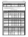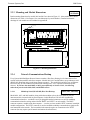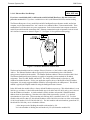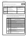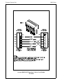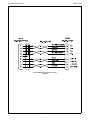
1
9000 Series
Intelligent Pressure Scanners
Users Manual
(Models 9010, 9015, 9016, 9020, 9021)
!
4th Edition
March 1998
!
Pressure Systems, Inc.
34 Research Drive
Hampton, Virginia 23666
(757) 865-1243
FAX (757) 766-2644
E-Mail: [email protected]
Web: www.psih.com
Pressure Systems, Inc.
REV
1
2
3
9000 Series
REVISION HISTORY
Original - 2nd Edition
3rd Edition (add Model 902x and 9016)
4th Edition
-i-
PRINT
DATE
4/94
11/97
3/98
Pressure Systems, Inc.
9000 Series
PREFACE
This manual describes all the System 9000 Intelligent Pressure Scanner modules (models 9010,
9015, 9016, 9020 and 9021). It is divided into seven (7) chapters and several (7) appendixes,
each covering a specific topic. These are summarized below:
Chapter 1: General Information:
describes the Models 901x and 902x Intelligent
Pressure Scanners, their specifications, and their
various options.
Chapter 2: Installation and Set Up:
describes the unpacking and inspection of a module,
and its connection to power, pressure, and a
communications network.
Chapter 3: Programming & Operation:
provides the information needed to program a
module from a host computer, and to get meaningful
data from it.
Chapter 4: Calibration:
describes methods of calibrating a module.
Chapter 5: Service:
describes general safety precautions and
maintenance procedures.
Chapter 6: Trouble Shooting:
describes module troubleshooting techniques.
Appendix A:
Appendix B:
Appendix C:
Appendix D:
Appendix E:
Appendix F:
Appendix G:
Appendix H:
Appendix I:
All Commands — Quick Reference
Response Error Codes
ASCII to Decimal/Hexadecimal Conversion Chart
Binary Bit Map
Cable Diagrams
System 9000 Products
Programming Example - BASIC
Module Mounting Dimensions
9000 Range Codes
Other System 9000 modules (e.g., models 903x) are documented in their own separate user’s
manuals. See APPENDIX F for a list of all System 9000 modules.
- ii -
Pressure Systems, Inc.
9000 Series
DISCLAIMER
This document is thoroughly edited and believed to be entirely reliable. Pressure Systems, Inc.
(PSI) assumes no responsibility for inaccuracies. All computer programs supplied in this manual
are written and tested on available systems at the factory. PSI assumes no responsibility for other
computers, languages, or operating systems. PSI reserves the right to change the specifications
without notice.
WARRANTY
PSI warrants that System 9000 products are free from defects in material and workmanship under
normal use and service for one year. PSI's liability under this warranty is limited to replacing or
repairing any unit the factory deems to be defective in parts or workmanship. The unit(s) must be
shipped to the factory at the customer's expense for inspection to determine repairs or
replacement. This warranty shall not apply to any unit(s) damaged from misuse, negligence,
accidents, incorrect electrical connections, application of excessive signal levels, repairs, or
alterations by the user.
FIRMWARE
This manual was prepared for various versions of module firmware, as was released in late 1997.
Addenda will be distributed as deemed necessary by PSI. Any questions regarding firmware
upgrades may be addressed to the Applications Engineering Department. Firmware revisions,
manual addenda, and utility software may also be obtained from the PSI web page at
www.psih.com.
Optomux is a registered trademark of OPTO 22 Corporation.
Bitbus is a trademark of Intel Corporation.
Krytox is a registered trademark of E.I. DuPont De Nemours & Co.
- iii -
Pressure Systems, Inc.
9000 Series
TABLE OF CONTENTS
Chapter 1 - General Information . . . . . . . . . . . . . . . . . . . . . . . . . . . . . . . . . . . . . . . . . . .
1.1
Introduction . . . . . . . . . . . . . . . . . . . . . . . . . . . . . . . . . . . . . . . . . . . . . . . . . . . . . .
1.2
Specifications . . . . . . . . . . . . . . . . . . . . . . . . . . . . . . . . . . . . . . . . . . . . . . . . . . . . .
1.3
Description of Instruments . . . . . . . . . . . . . . . . . . . . . . . . . . . . . . . . . . . . . . . . . . .
1.4
Options . . . . . . . . . . . . . . . . . . . . . . . . . . . . . . . . . . . . . . . . . . . . . . . . . . . . . . . . .
1.4.1
Pressure Ranges . . . . . . . . . . . . . . . . . . . . . . . . . . . . . . . . . . . . . . . . . . . .
1.4.2
Manifolds and Pressure Connections . . . . . . . . . . . . . . . . . . . . . . . . . . . .
1.4.3
Communication Interfaces . . . . . . . . . . . . . . . . . . . . . . . . . . . . . . . . . . . .
1-1
1-1
1-3
1-6
1-7
1-7
1-7
1-8
Chapter 2 - Installation and Set Up . . . . . . . . . . . . . . . . . . . . . . . . . . . . . . . . . . . . . . . . . . 2-1
2.1
Unpacking and Inspection . . . . . . . . . . . . . . . . . . . . . . . . . . . . . . . . . . . . . . . . . . . 2-1
2.2
Safety Considerations . . . . . . . . . . . . . . . . . . . . . . . . . . . . . . . . . . . . . . . . . . . . . . . 2-1
2.3
Preparation for Use . . . . . . . . . . . . . . . . . . . . . . . . . . . . . . . . . . . . . . . . . . . . . . . . 2-1
2.3.1
Environment . . . . . . . . . . . . . . . . . . . . . . . . . . . . . . . . . . . . . . . . . . . . . . 2-1
2.3.2
Power . . . . . . . . . . . . . . . . . . . . . . . . . . . . . . . . . . . . . . . . . . . . . . . . . . . 2-2
2.3.3
Mounting and Module Dimensions . . . . . . . . . . . . . . . . . . . . . . . . . . . . . . 2-3
2.3.4
Network Communications Hookup . . . . . . . . . . . . . . . . . . . . . . . . . . . . . 2-3
2.3.4.1
Multidrop Serial (RS-422/485) Host Port Hookup . . . . . . . . . 2-3
2.3.4.1.1
Host Port Connection . . . . . . . . . . . . . . . . . . . . . . . . . 2-4
2.3.4.1.2
Multiple Module Connections . . . . . . . . . . . . . . . . . . . 2-4
2.3.4.1.3
Multidrop Cable Lengths . . . . . . . . . . . . . . . . . . . . . . . 2-6
2.3.4.1.4
Multidrop Cable Termination . . . . . . . . . . . . . . . . . . . . 2-6
2.3.4.1.5
Multidrop Node Address Selection . . . . . . . . . . . . . . . 2-7
2.3.4.1.6
Selecting Baud Rate and Data Averaging . . . . . . . . . . . 2-7
2.3.4.2
Ethernet Host Port Hookup . . . . . . . . . . . . . . . . . . . . . . . . . . . 2-9
2.3.5
Diagnostic Port Hookup . . . . . . . . . . . . . . . . . . . . . . . . . . . . . . . . . . . . . 2-12
2.3.6
Pressure Connections . . . . . . . . . . . . . . . . . . . . . . . . . . . . . . . . . . . . . . . 2-13
2.3.6.1
RUN Mode Inputs . . . . . . . . . . . . . . . . . . . . . . . . . . . . . . . . . 2-14
2.3.6.2
CAL Mode Inputs . . . . . . . . . . . . . . . . . . . . . . . . . . . . . . . . . 2-14
2.3.6.3
Purge Mode Inputs . . . . . . . . . . . . . . . . . . . . . . . . . . . . . . . . 2-14
2.3.6.4
Leak Mode Inputs . . . . . . . . . . . . . . . . . . . . . . . . . . . . . . . . . 2-15
2.3.6.5
Supply Air . . . . . . . . . . . . . . . . . . . . . . . . . . . . . . . . . . . . . . . 2-15
2.3.7
9020 and 9021 Transducer Installation . . . . . . . . . . . . . . . . . . . . . . . . . . 2-16
2.3.7.1
Installation of 9400, 9401, and 9402 Transducers . . . . . . . . . 2-16
2.3.7.2
Installation of All Other Transducers . . . . . . . . . . . . . . . . . . . 2-17
2.3.8
Case Grounding . . . . . . . . . . . . . . . . . . . . . . . . . . . . . . . . . . . . . . . . . . . 2-17
2.3.9
Trigger Input Signal . . . . . . . . . . . . . . . . . . . . . . . . . . . . . . . . . . . . . . . . 2-17
2.3.10 Power Up Checks and Self Diagnostics . . . . . . . . . . . . . . . . . . . . . . . . . 2-17
Chapter 3 - Programming and Operation . . . . . . . . . . . . . . . . . . . . . . . . . . . . . . . . . . . . .
3.1
Commands and Responses . . . . . . . . . . . . . . . . . . . . . . . . . . . . . . . . . . . . . . . . . . .
3.1.1
Introduction . . . . . . . . . . . . . . . . . . . . . . . . . . . . . . . . . . . . . . . . . . . . . . .
3.1.1.1
Optomux Protocol . . . . . . . . . . . . . . . . . . . . . . . . . . . . . . . . .
3.1.1.2
TCP/IP Protocol . . . . . . . . . . . . . . . . . . . . . . . . . . . . . . . . . . .
- iv -
3-1
3-1
3-1
3-1
3-1
Pressure Systems, Inc.
9000 Series
TABLE OF CONTENTS (continued)
3.1.2
3.2
3.3
Commands . . . . . . . . . . . . . . . . . . . . . . . . . . . . . . . . . . . . . . . . . . . . . . . . 3-2
3.1.2.1
General Command Format . . . . . . . . . . . . . . . . . . . . . . . . . . . . 3-2
3.1.2.2
Node Address Field . . . . . . . . . . . . . . . . . . . . . . . . . . . . . . . . . 3-2
3.1.2.3
Command Field . . . . . . . . . . . . . . . . . . . . . . . . . . . . . . . . . . . . 3-3
3.1.2.4
Position Field . . . . . . . . . . . . . . . . . . . . . . . . . . . . . . . . . . . . . 3-3
3.1.2.5
Modifier Field . . . . . . . . . . . . . . . . . . . . . . . . . . . . . . . . . . . . . 3-3
3.1.2.6
Checksum Field . . . . . . . . . . . . . . . . . . . . . . . . . . . . . . . . . . . . 3-4
3.1.3
Responses . . . . . . . . . . . . . . . . . . . . . . . . . . . . . . . . . . . . . . . . . . . . . . . . 3-5
3.1.3.1
Interpreting Scaled Analog Data . . . . . . . . . . . . . . . . . . . . . . . 3-6
3.1.3.2
Interpreting Scaled Offset Values . . . . . . . . . . . . . . . . . . . . . . 3-7
3.1.3.3
Interpreting Scaled Gain Values . . . . . . . . . . . . . . . . . . . . . . . . 3-7
3.1.3.4
Interpreting IEEE Floating-Point Values . . . . . . . . . . . . . . . . . 3-8
3.1.3.5
Reading TCP/IP Response Data . . . . . . . . . . . . . . . . . . . . . . . 3-8
3.1.3.6
Interpretting Engineering Units Output . . . . . . . . . . . . . . . . . . 3-9
3.1.4
Functional Command Overview . . . . . . . . . . . . . . . . . . . . . . . . . . . . . . . 3-10
3.1.4.1
Startup Initialization . . . . . . . . . . . . . . . . . . . . . . . . . . . . . . . 3-10
3.1.4.2
Scan Definition for Acquisition . . . . . . . . . . . . . . . . . . . . . . . 3-11
3.1.4.3
Calibration of Engineering-Unit Coefficients . . . . . . . . . . . . . 3-11
3.1.4.4
Acquisition/Delivery of Data to Host . . . . . . . . . . . . . . . . . . . 3-12
3.1.4.5
Other Functions . . . . . . . . . . . . . . . . . . . . . . . . . . . . . . . . . . . 3-13
Detailed Command Description Reference . . . . . . . . . . . . . . . . . . . . . . . . . . . . . . 3-14
A
Power Up Clear . . . . . . . . . . . . . . . . . . . . . . . . . . . . . . . . . . . . . . . . . . 3-15
B
Reset . . . . . . . . . . . . . . . . . . . . . . . . . . . . . . . . . . . . . . . . . . . . . . . . . . . 3-16
L
Read Scaled Analog Inputs . . . . . . . . . . . . . . . . . . . . . . . . . . . . . . . . . . 3-17
V
Read Transducer Voltages . . . . . . . . . . . . . . . . . . . . . . . . . . . . . . . . . . . 3-19
Z
Calculate and Set Gains . . . . . . . . . . . . . . . . . . . . . . . . . . . . . . . . . . . . . 3-21
a
Read Transducer A/D Counts . . . . . . . . . . . . . . . . . . . . . . . . . . . . . . . . . 3-23
b
Read High-Speed Data . . . . . . . . . . . . . . . . . . . . . . . . . . . . . . . . . . . . . . 3-25
c
Define/Control Host Stream(s) . . . . . . . . . . . . . . . . . . . . . . . . . . . . . . . . 3-26
h
Calculate and Set Offsets . . . . . . . . . . . . . . . . . . . . . . . . . . . . . . . . . . . . 3-33
m
Read Temperature A/D Counts . . . . . . . . . . . . . . . . . . . . . . . . . . . . . . . 3-35
n
Read Temperature Voltages . . . . . . . . . . . . . . . . . . . . . . . . . . . . . . . . . . 3-37
q
Read Module Status . . . . . . . . . . . . . . . . . . . . . . . . . . . . . . . . . . . . . . . . 3-39
r
Read High Precision Data . . . . . . . . . . . . . . . . . . . . . . . . . . . . . . . . . . . 3-41
t
Read Transducer Temperatures . . . . . . . . . . . . . . . . . . . . . . . . . . . . . . . 3-43
u
Read Internal Coefficients . . . . . . . . . . . . . . . . . . . . . . . . . . . . . . . . . . . 3-45
v
Download Internal Coefficients . . . . . . . . . . . . . . . . . . . . . . . . . . . . . . . 3-49
w
Set Operating Options . . . . . . . . . . . . . . . . . . . . . . . . . . . . . . . . . . . . . . 3-51
Obsolete Commands . . . . . . . . . . . . . . . . . . . . . . . . . . . . . . . . . . . . . . . . . . . . . . 3-54
-v-
Pressure Systems, Inc.
9000 Series
TABLE OF CONTENTS (continued)
Chapter 4 - Calibration . . . . . . . . . . . . . . . . . . . . . . . . . . . . . . . . . . . . . . . . . . . . . . . . . . . .
4.1
Introduction . . . . . . . . . . . . . . . . . . . . . . . . . . . . . . . . . . . . . . . . . . . . . . . . . . . . . .
4.2
Rezero Calibration . . . . . . . . . . . . . . . . . . . . . . . . . . . . . . . . . . . . . . . . . . . . . . . . .
4.2.1
Rezero Calibration Valve Control . . . . . . . . . . . . . . . . . . . . . . . . . . . . . . .
4.2.2
Rezero Calibration Summary . . . . . . . . . . . . . . . . . . . . . . . . . . . . . . . . . .
4.3
Span Calibration . . . . . . . . . . . . . . . . . . . . . . . . . . . . . . . . . . . . . . . . . . . . . . . . . .
4.3.1
Span Calibration Valve Control . . . . . . . . . . . . . . . . . . . . . . . . . . . . . . . .
4.3.2
Span Calibration Summary . . . . . . . . . . . . . . . . . . . . . . . . . . . . . . . . . . . .
4.4
Coefficient Storage . . . . . . . . . . . . . . . . . . . . . . . . . . . . . . . . . . . . . . . . . . . . . . . .
4-1
4-1
4-3
4-3
4-4
4-5
4-5
4-6
4-7
Chapter 5 - Service . . . . . . . . . . . . . . . . . . . . . . . . . . . . . . . . . . . . . . . . . . . . . . . . . . . . . . . 5-1
5.1
Maintenance . . . . . . . . . . . . . . . . . . . . . . . . . . . . . . . . . . . . . . . . . . . . . . . . . . . . . 5-1
5.1.1
Common Maintenance . . . . . . . . . . . . . . . . . . . . . . . . . . . . . . . . . . . . . . . 5-3
5.1.2
Module Disassembly . . . . . . . . . . . . . . . . . . . . . . . . . . . . . . . . . . . . . . . . 5-4
5.1.3
Electronic Circuit Board Replacement . . . . . . . . . . . . . . . . . . . . . . . . . . . 5-5
5.1.3.1
PC-206 Amplifier/Multiplexer Board . . . . . . . . . . . . . . . . . . . . 5-5
5.1.3.2
PC-242 Amplifier/Multiplexer Board . . . . . . . . . . . . . . . . . . . . 5-6
5.1.3.3
PC-203 Microprocess/A-D Board . . . . . . . . . . . . . . . . . . . . . . 5-7
5.1.3.4
PC-280 Microprocess/A-D/Ethernet Board . . . . . . . . . . . . . . . 5-8
5.1.4
Replacement of Transducers . . . . . . . . . . . . . . . . . . . . . . . . . . . . . . . . . . . 5-9
5.1.5
Calibration Valve Solenoid Replacement . . . . . . . . . . . . . . . . . . . . . . . . 5-10
5.1.6
Replacement of O-Rings . . . . . . . . . . . . . . . . . . . . . . . . . . . . . . . . . . . . 5-11
5.1.6.1
DH200 O-Ring Replacement . . . . . . . . . . . . . . . . . . . . . . . . . 5-11
5.1.6.2
Tubing Plate O-Ring Replacement . . . . . . . . . . . . . . . . . . . . . 5-12
5.1.6.3
Adapter Plate O-Ring Replacement . . . . . . . . . . . . . . . . . . . . 5-13
5.1.6.4
Calibration Manifold Piston O-Ring Replacement . . . . . . . . . 5-14
5.1.6.5
Calibration Valve Solenoid O-Ring Replacement . . . . . . . . . . 5-14
5.2
Upgrading Module Firmware . . . . . . . . . . . . . . . . . . . . . . . . . . . . . . . . . . . . . . . . 5-16
5.2.1
Upgrading Firmware Via Diagnostic Port . . . . . . . . . . . . . . . . . . . . . . . . 5-16
5.2.2
Upgrading Firmware Via Host TCP/IP Port . . . . . . . . . . . . . . . . . . . . . . 5-17
Chapter 6 - Troubleshooting Guide . . . . . . . . . . . . . . . . . . . . . . . . . . . . . . . . . . . . . . . . . .
6.1
Optomux Module Troubleshooting . . . . . . . . . . . . . . . . . . . . . . . . . . . . . . . . . . . .
6.1.1
Checking Optomux Module Operation . . . . . . . . . . . . . . . . . . . . . . . . . . .
6.1.2
Checking Host PC Operation . . . . . . . . . . . . . . . . . . . . . . . . . . . . . . . . . .
6.1.3
Checking System 9000 Interface Wiring . . . . . . . . . . . . . . . . . . . . . . . . . .
6.1.3.1
RS-232 Diagnostic Port Operation . . . . . . . . . . . . . . . . . . . . .
6.1.3.2
RS-422 Multidrop Host Port Operation . . . . . . . . . . . . . . . . . .
6.1.4
Network Communications Testings Hints . . . . . . . . . . . . . . . . . . . . . . . . .
6.2
Ethernet Module Troubleshooting . . . . . . . . . . . . . . . . . . . . . . . . . . . . . . . . . . . . .
6.2.1
Checking Module Power-up Sequence . . . . . . . . . . . . . . . . . . . . . . . . . . .
- vi -
6-1
6-1
6-1
6-2
6-2
6-2
6-3
6-5
6-6
6-6
Pressure Systems, Inc.
9000 Series
TABLE OF CONTENTS (continued)
6.2.2
6.3
Checking Module TCP/IP Communications . . . . . . . . . . . . . . . . . . . . . . . 6-7
6.2.2.1 Module IP Address Assignment . . . . . . . . . . . . . . . . . . . . . . . . . . 6-7
6.2.2.2 Host IP Address Assignment . . . . . . . . . . . . . . . . . . . . . . . . . . . . 6-7
6.2.2.3 Verifying Host TCP/IP Communications . . . . . . . . . . . . . . . . . . . 6-8
Zero and Gain Calibration Troubleshooting . . . . . . . . . . . . . . . . . . . . . . . . . . . . . 6-10
APPENDICES
Appendix A:
Appendix B:
Appendix C:
Appendix D:
Appendix E:
Appendix F:
Appendix G:
Appendix H:
Appendix I:
Index:
All Optomux Commands — Quick Reference
Optomux Response Error Codes
ASCII to Decimal/Hexadecimal Conversion Chart
Binary Bit Map
Cable Diagrams
System 9000 Products
Programming Example -BASIC
Module Mounting Dimensions
9000 Range Codes
LIST OF FIGURES
Figure 1.1:
System 9000 Intelligent Pressure Scanners (Models 9015, 9020 and 9016) . . . 1-2
Figure 2.1:
Figure 2.2:
Figure 2.3:
Figure 2.4:
Figure 2.5:
Figure 2.6:
Figure 2.7:
Figure 2.8:
Figure 2.9:
Figure 2.10:
9010, 9015, 9020 Power Pin Assignments . . . . . . . . . . . . . . . . . . . . . . . . . . . 2-2
9016, 9021 Power Pin Assignments . . . . . . . . . . . . . . . . . . . . . . . . . . . . . . . . 2-2
Mounting Dimensions . . . . . . . . . . . . . . . . . . . . . . . . . . . . . . . . . . . . . . . . . . . 2-3
RS-422/485 Host Port Connectors . . . . . . . . . . . . . . . . . . . . . . . . . . . . . . . . . 2-4
RS-422/485 Multidrop Network . . . . . . . . . . . . . . . . . . . . . . . . . . . . . . . . . . . 2-5
Address DIP Switch . . . . . . . . . . . . . . . . . . . . . . . . . . . . . . . . . . . . . . . . . . . . 2-8
Ethernet Host Port Connector Pins . . . . . . . . . . . . . . . . . . . . . . . . . . . . . . . . . 2-9
Ethernet Network Topology . . . . . . . . . . . . . . . . . . . . . . . . . . . . . . . . . . . . . 2-11
9020 Transducer Wiring . . . . . . . . . . . . . . . . . . . . . . . . . . . . . . . . . . . . . . . . 2-16
9021 Transducer Wiring . . . . . . . . . . . . . . . . . . . . . . . . . . . . . . . . . . . . . . . . 2-16
Figure 4.1:
Figure 4.2:
Figure 4.3:
Figure 4.4:
Calibration Manifold RUN Position . . . . . . . . . . . . . . . . . . . . . . . . . . . . . . . .
Calibration Manifold CAL Position . . . . . . . . . . . . . . . . . . . . . . . . . . . . . . . . .
Calibration Manifold PURGE Position . . . . . . . . . . . . . . . . . . . . . . . . . . . . . .
Calibration Manifold LEAK CHARGE Position . . . . . . . . . . . . . . . . . . . . . . .
- vii -
4-2
4-2
4-2
4-2
Pressure Systems, Inc.
9000 Series
TABLE OF CONTENTS (continued)
Figure 5.1:
Figure 5.2:
Figure 5.3:
Figure 5.4:
Figure 5.5:
Figure 5.6:
Figure 5.7:
Figure 5.8:
Exploded View of the Model 9010 . . . . . . . . . . . . . . . . . . . . . . . . . . . . . . . . . 5-1
Exploded View of the Model 9016 . . . . . . . . . . . . . . . . . . . . . . . . . . . . . . . . . 5-2
9010 Instrument Out of Extrusion . . . . . . . . . . . . . . . . . . . . . . . . . . . . . . . . . 5-4
9016 Instrument Out of Extrusion . . . . . . . . . . . . . . . . . . . . . . . . . . . . . . . . . 5-4
PC-203 Board . . . . . . . . . . . . . . . . . . . . . . . . . . . . . . . . . . . . . . . . . . . . . . . . 5-7
PC-280 Board . . . . . . . . . . . . . . . . . . . . . . . . . . . . . . . . . . . . . . . . . . . . . . . . 5-8
Top View of DH200 . . . . . . . . . . . . . . . . . . . . . . . . . . . . . . . . . . . . . . . . . . . . 5-9
Solenoid in Module . . . . . . . . . . . . . . . . . . . . . . . . . . . . . . . . . . . . . . . . . . . 5-10
LIST OF TABLES
Table 1.1:
Table 1.2:
Specifications . . . . . . . . . . . . . . . . . . . . . . . . . . . . . . . . . . . . . . . . . . . . . . . . . 1-3
More Specifications . . . . . . . . . . . . . . . . . . . . . . . . . . . . . . . . . . . . . . . . . . . . 1-4
Table 2.1:
Table 2.2:
Configuration Switch Definitions . . . . . . . . . . . . . . . . . . . . . . . . . . . . . . . . . . 2-8
Diagnostic Port Wiring . . . . . . . . . . . . . . . . . . . . . . . . . . . . . . . . . . . . . . . . . 2-12
Table 3.1:
Table 3.2:
Table 3.3:
Optomux Error Codes . . . . . . . . . . . . . . . . . . . . . . . . . . . . . . . . . . . . . . . . . . 3-5
Optomux Output Valves . . . . . . . . . . . . . . . . . . . . . . . . . . . . . . . . . . . . . . . . . 3-6
All Optomux Commands . . . . . . . . . . . . . . . . . . . . . . . . . . . . . . . . . . . . . . . 3-14
Table 5.1:
Component Cross Reference . . . . . . . . . . . . . . . . . . . . . . . . . . . . . . . . . . . . . . 5-2
- viii -
Pressure Systems, Inc.
9000 Series
Chapter 1
General Information
1.1
Introduction
This manual contains the information needed to install, operate, and program the System 9000 Intelligent
Pressure Scanner modules (model series 901x and 902x). Where applicable, each section is labelled as to
which models it applies.
Models 9010, 9015, and 9016 are pneumatic intelligent pressure scanners — each with integral pressure
transducers and a pneumatic calibration manifold. They differ primarily in the number of pressure
transducers (8 or 16 of the DH200 type), type of pressure fittings, accuarcy, measurement speed, and type of
host communications interface.
Models 9020 and 9021 are all-media intelligent pressure scanners which may be fitted with up to twelve (12)
external all-media (9400, 9401, 9402 or third party) transducers. Because of the external nature of these
transducers, and the variety of pneumatic or hydraulic media supported, the 9020 and 9021 do not contain an
integral calibration manifold.
All models provide engineering unit pressure data with guaranteed system accuracy. This is achieved by
reading factory-determined pressure and temperature engineering-unit data conversion coefficients from
their transducers’ nonvolatile memories at power-up. They also allow additional adjustment coefficients to
be “fine-tuned” with a 1- or 2-point (zero and span) calibration under host control (e.g., possibly utilizing
optional Pressure Systems 903x Pressure Calibrator modules).
All models may be interconnected into a network via their Host Port — normally using multidrop RS422/485
asynchronous serial communications (with Optomux protocol). The models 9016 and 9021 provide 10Base-T Ethernet communications for their Host Port (with TCP/IP protocol and Optomux type command
format).
All models have a separate RS-232 Diagnostic Port which may be used for diagnostic checks of the module
or as an interface to upgrade module firmware.
1-1
Pressure Systems, Inc.
9000 Series
Model 9015
Model 9020
Model 9016
Figure 1.1: System 9000 Pneumatic Intelligent Pressure Scanners
1-2
Pressure Systems, Inc.
1.2
9000 Series
Specifications
Specifications for the various Intelligent Pressure Scanner models are listed in the following tables.
Table 1.1: Specifications
Parameter
9010
9015
9016
902x
16
12
Units
Comments
PRESSURE CHARACTERISTICS
Number of
Pressure Inputs
Pressure Ranges1
Media
Proof Pressure2
Burst Pressure
16
8
10 " H2O (2.5 kPa)
20 " H2O (5.0 kPa)
9400
Gauge
1 (7)
2.5 (17)
5 (35)
10 (70)
15 (105)
30 (210)
45 (310)
100 (700)
250 (1720)
500 (3450)
600 (4100)
750 (5200)
5 (35)
10 (70)
15 (105)
50 (350)
100 (700)
250 (1725)
500 (3500)
750 (5200)
1500 (10400)
3000 (20800)
5000 (35000)
10000(69000
)
Dry, non-corrosive gas
9401
Absolute
Mixed ranges allowed
9402
Diff
5 (35)
15 (105)
10 (70)
30 (210)
15 (105)
50 (350)
50 (350)
100 (700)
100 (700)
250 (1725) 250 (1725)
500 (3500)
750 (5200)
1500 (10400)
3000 (20800)
5000 (35000)
10000(69000)
9400 Gauge ranges > 750
psi (5200 kPa) are sealed
gauge.
psi (kPa)
compatible w/316 SS & Viton
3.0X @ < 15 psi
2.0X @ 15-100 psi
1.5X @ > 100 psi
3.0X @ # 100 psi
1.5X @ >100 psi
5.0X @ <15 psi
3.0X @ 15-100 psi
2.0X @ > 100 psi
5.0X @ <750 psi
3.0X @ 750-3000 psi
2.0X @ >3000 psi
940x Ranges > 750 psi
have passive
compensation only
other materials available
F.S. min
see ranges above for kPa
equivalent.
F.S. min
see ranges above for kPa
equivalent.
Max Reference
Pressure
100 (700)
250 (1725)
n.a.
-
psi (kPa)
psi (kPa)
Ranges #5 psi (35 kPa)
Ranges >5 psi (35 kPa)
Manifold Control
Pressure
80 (560)
125 (860)
n.a.
-
psi (kPa)
Min
Max
> max input pressure
800 (5600)
n.a.
-
psi (kPa)
Min
Max
Purge Pressure
(Use of purge
is optional)
STATIC ACCURACY, RESOLUTION, & THERMAL STABILITY
±0.003
Measurement
Resolution
% F.S.
Static Accuracy3
901x After Rezero
Cal
±0.15
±0.08
±0.15
±0.05
-
901x After Span
Cal
±0.10
±0.05
N/A
N/A
-
902x with digital
comp
902x with no
digital comp
% F.S.
% F.S.
Range # 2.5 psi (20 kPa)
Range > 2.5 psi (20 kPa)
Range # 2.5 psi (20 kPa)
Range > 2.5 psi (20 kPa)
±0.10
% FS
940x Range # 750 psi
±0.50
% FS
940x Range > 750 psi
±0.005
±0.05
% FS/ºC
% FS/ºC
% FS/ºC
% FS/ºC
Range # 2.5 psi (20 kPa)
Range > 2.5 psi (20 kPa)
940x with digital comp
940x with analog comp
Range # 5 psi ( 35 kPa)
Range > 5 psi (35 kPa) &
Range < 100 psi (700kPa)
Range$ 100 psi (700 kPa)
Total Thermal
Error4
±0.0015
±0.001
Line Pressure
Effect
±0.001
±0.0008
n.a.
-
% FS/psi
% FS/psi
±0.0003
-
% FS/psi
1-3
Pressure Systems, Inc.
Parameter
9010
9000 Series
9015
9016
902x
--
Voltage
Measurement5
Units
±0.025
±0.025
±0.05
±0.05
%F.S.
%F.S.
%F.S.
%F.S.
Comments
-4500 to 4500 mV
-250 to 250 mV
-100 to 100 mV
-50 to 50 mV
Notes (Table 1.1 above):
1
2
3
4
5
Standard ranges listed, consult factory for special ranges
Maximum applied pressure without reducing sensor performance within operating pressure range.
Static accuracy includes combined errors due to non-linearity, hysteresis and non-repeatability per ISA S51.1.
Includes thermal effects of zero & span relative to 25ºC.
For 902x scanned channels used in voltage measurement mode.
Table 1.2: More Specifications
Parameter
9010
9015
9016
9020
9021
Units
Comments
30
-
100
20
-
20
meas/ch/sec
meas/ch/sec
9010, 9015, 9020
Ethernet avail.on 9016
and 9021
9010, 9015, 9020 only
DATA SCAN & TRANSFER RATES
Measurement Scan Rate
via RS422/485 Host Port
via Ethernet Host Port
20
-
Host Port Baud Rate
RS422/485 (Optomux)
1200 to 38400
-
1200 to
38400
-
Baud
-
10
-
10
Mbits/sec.
9600
9600
9600
9600
Baud
!15 ±1 a
18 to 36 b
!15 ±1
18 to 36 b
VDC
-
15 ±1
200
50
Ethernet (TCP/IP)
Diagnostic Port Baud Rate
9016, 9021 only
POWER/SIGNAL REQUIREMENTS
V1
V2
15 ±1
I1
50
a
VDC
200
270
mA
mA
9010, 9015, 9020 only
w/out internal purge
solenoids on
w/ internal purge
solenoids on
400
-
200
--
mA
-
2.5
-
2.5
VDC
0 to 50
0 to 50
0 to 50
ºC
Consult factory for
extended temps
!20 to 60
-20 to 70
0 to 70
ºC
-30 to 100
ºC
<95% non-condensing
humidity
940x transducers only
-20 to 80
ºC
I2
Hardware Trigger
Threshold
TTL compatible
diff.input,
±5 VDC common
mode (9016, 9021
only)
ENVIRONMENTAL/PHYSICAL
Calibrated Temp Range c
Operating Temp Range
Storage Temp
Size
Weight
!20 to 80
-20 to 80
9.5 x 3.5 x 4.0
(24 x 9 x 10)
4.25
(1.9)
-
9.5 x 3.5 x 3.5
(24 x 9 x 9)
inches
(cm)
LxWxH
4.25
(1.9)
--
--
lb
(kg)
901x w. Bulge tubing
plate
5.00
(2.25)
--
--
lb
(kg)
9015 w/c" NPT
tubing plate
6.5
(2.95)
2.0
(0.9)
lb
(kg)
9016, 9020
1-4
Pressure Systems, Inc.
9000 Series
Notes (Table 1..2):
a
For 901x units manufactured prior to Serial Number 200:
-V1 = -12 ± .6 VDC
+V2 = +12 ± .6 VDC
±V3
Do Not Connect - internally connected to +5V.
b
Unregulated Supply.
c
Consult factory for special temperature range calibrations.
1-5
Pressure Systems, Inc.
1.3
9000 Series
Description of Instruments
The System 9000 Intelligent Pressure Scanner modules are flexible pressure measuring devices intended for
use in test and production environments. Models are available with 8 (model 9015), 12 (model 9020/9021),
or 16 (model 9010/9016) channels, each with individual pneumatic or all-media transducers per channel. The
most distinctive features are highlighted below:
! Precalibrated Transducer - A memory chip containing full calibration data is embedded within each
internal transducer.
!
Individual transducer per measurement input channel - Mixed transducer ranges may be installed
in a single module.
!
Low Cost per Point - module per-channel cost is less than a typical industrial pressure
transducer/transmitter.
!
High Accuracy - Model 901x pressure scanners are capable of accuracies up to ±0.05% —
following single-point span calibration. Accuracy up to ±0.08% F.S. is maintained for twelve
months after calibration — through use of built-in rezero capabilities. Model 902x pressure
scanners are capable of accuracies of up to ±0.10% F.S. — following appropriate zero and span
calibration.
!
Low Thermal Errors - Each transducer of a pressure scanner module contains an individual
temperature sensor and thermal calibration data for internal use by software correction
algorithms. Thermal errors are reduced to ±0.001%/ºC over the calibrated temperature span.
!
Rezero Upon Demand (models 901x) - An integrated calibration valve allows for automatic
rezero adjustment calibration of dry gas transducers to null offset drift errors.
!
Ease of Transducer Replacement - Factory calibrated transducer assemblies may be stocked and
rapidly replaced in the field. Storage of thermal coefficients within the transducer allows for 'plug
and play' transducer replacement.
!
Ease of Calibration - Each 901x module contains a pneumatic calibration manifold and software
commands to automatically perform rezero and span adjustment calibrations. New offset and
gain coefficients that result from the most recent calibration may be stored in nonvolatile
transducer memory.
!
Measurement Flexibility - Each 902x module is capable of measuring general purpose voltage
signals on any channel not populated with a 9400 type transducer. Full-scale ranges of ±50,
±100, ±250 and ±4500 mV are supported through programmable gain amplifier circuitry.
!
Ease of Use - Modules have simple command sets and provide engineering units output. They
may interface directly to a desktop or laptop computer or they may be interconnected into a large
network controlled by any type of host computer.
!
Connectivity - Use of industry-standard communications network protocols to control and read
data from System 9000 modules allows distribution to the point of measurement and ensures
compatibility with third party hardware and software.
1-6
Pressure Systems, Inc.
1.4
Options
1.4.1
Pressure Ranges
9000 Series
Models 9010 and 9016 contain sixteen (16) DH200 transducers, while model 9015 contains eight (8). These
DH200 transducers are available with full scale pressure ranges from 10" H2O (inches of water column) to
750 psid (2.5 kPa to 5200 kPa). Transducers with different pressure ranges may be combined in a single
module.
The models 9020 and 9021 can attach up to twelve (12) series 940x or third party external all-media
transducers. The 9400 gauge-type transducers are available with full-scale pressure ranges from 5 psi to
10,000 psi (35 kPa to 69000 kPa). The 9401 absolute-type transducers are available with full-scale pressure
ranges from 15 psi to 10,000 psi (105 kPa to 69000 kPa). The 9402 wet-wet differential type transducers
are available with full scale ranges from 5 psi to 250 psi (35 kPa to 1725 kPa). Transducers with different
pressure ranges may be attached to a single module.
All standard pressure ranges of each transducer type are listed in Table 1.1. Please consult the Sales
Department at Pressure Systems for availability of other pressure ranges.
1.4.2
Manifolds and Pressure Connections
The model 9010 sixteen-channel Intelligent Pressure Scanner is offered with true differential (reference per
channel) or common reference pneumatic manifolds. It is available with .063" (1.60 mm) bulge tubulation
only, which can be seen in Figure 1.1. It is supplied with a standard purge and leak check calibration
manifold.
The model 9015 eight-channel Intelligent Pressure Scanner is also available with a true differential or
common reference pneumatic manifold. It is available with .063" bulge tubulation or optional
c"compression fittings (common reference only). The latter type of pneumatic connections can be see in
Figure 1.1. It is also supplied with a standard purge and leak check calibration manifold.
The model 9016 sixteen-channel Intelligent Pressure Scanner is also available with a true differential or
common reference pneumatic manifold, and has a standard purge and leak check manifold. It is available
with standard c" or optional 1/16" and 1/4" compression fittings. All fittings utilize an SAE 5/16 - 24 oring boss which supports a variety of other adapter compression fittings. It is also available with a quick
disconnect plate which contains 0.063" bulge tubulation. The common differential version is available with
all choices of fittings. The true differential version is available with 0.063" bulged tubulaton fittings only.
The model 9020 and 9021 12-channel Intelligent Pressure Scanners have no internal manifold or pressure
transducers. Instead, it allows external connection of up to twelve (12) type 9400, 9401, or 9402 all-media
pressure transducers. 9400, 9401, and 9402 transducers may be purchased with a variety of standard
pressure fittings. Any necessary valves and manifolds must be customer-supplied if automatic calibration
with the appropriate medium is desired at the module installation site.
Consult the Sales Department at Pressure Systems for availability of other input fittings.
1-7
Pressure Systems, Inc.
9000 Series
1.4.3 Communication Interfaces
All standard System 9000 Intelligent Pressure Scanners provide digitally temperature compensated and
linearized pressure data in engineering units through a serial communications interface to a host computer.
The models 9016 and 9021 have a 10-Base-T Ethernet host communications interface using industry
standard TCP/IP protocol. This interface provides high data transfer rates and system connectivity.
The models 9010, 9015, and 9020 have an asynchronous RS-422/485 host communications interface. These
models also include a standard RS-232 diagnostic interface that may also be used as a host interface.
The Optomux style command set is used to send commands and receive responses from all ports. This
includes the Ethernet Host Port of the model 9016 and 9021, as well as the standard Diagnostic Port of the
model 9010, 9015, and 9020.
1-8
Pressure Systems, Inc.
9000 Series
Chapter 2
Installation and Set Up
2.1
Unpacking and Inspection
The System 9000 product family has many components which may be purchased either as an entire system,
or as individual pieces of equipment. Before assembling the system, use the shipping bill as a reference to
ensure that all parts have arrived. Pressure Systems takes no responsibility for equipment that is damaged
during shipment. If containers are broken, ripped, or damaged, contact the transportation carrier. If the
equipment appears to be damaged, contact the Repair Department at Pressure Systems.
Each System 9000 Intelligent Pressure Scanner shipment will contain the following minimum components:
!
!
!
!
!
Model 901x or 902x Intelligent Pressure Scanner module
Diagnostic Port Cable (Models 9010, 9015, and 9020 only, one per order)
PC-221 Diagnostic Loopback Connector (Models 9010, 9015, 9020 only, one per order)
Start-up Software Diskette
System 9000 User’s Manual for Intelligent Pressure Scanners (Models 901x/902x)
2.2
Safety Considerations
Always wear safety glasses when operating this equipment or when working with pressurized lines. Always
ensure that high pressure lines are properly secured.
All system power should be off during installation or removal of any components from a System 9000
module. Failure to turn power off prior to installation may cause permanent damage to the module. Use
caution and check line voltages before applying power to the module.
2.3
Preparation for Use
2.3.1
Environment
All Models
All standard Intelligent Pressure Scanners are factory calibrated to be accurate over a specified temperature
range, but may be operated or stored over a wider temperature range (see Environmental/Physical
Specifications in Table 1.2 in Chapter 1) . Operating or storing an instrument outside its specified range(s)
will result in a loss of measurement accuracy and may cause permanent damage to the instrument electronics.
WARNING: Exceeding the specified storage or operating temperatures
may result in permanent damage to the System 9000 electronics.
2-1
Pressure Systems, Inc.
9000 Series
All Models
2.3.2 Power
The model 9016 and 9021 Intelligent Pressure Scanners need only a single unregulated power supply. All
other models (9010, 9015, and 9020) require dual regulated input voltages.1 See Table 1.2 in Chapter 1 for
actual power requirements by model number.
Figure 2.1 shows pin assignments for the module’s top-panel power connector. This is labeled “PWR” for
models 9010, 9015, and 9020. Model 9016 and 9021 have a single military-style circular connector through
which all power and input/output signals pass as shown in Figure 2.2.
WARNING: Improper connection of power to the Intelligent Pressure
Scanner can result in permanent damage to module electronics.
-V1
L
+V2
COM
-V3
PWR
P
+V3
R
E
S
PWR
S
Figure 2.1:
9010,9015,9020 Power Pin Assignments
Figure 2.2:
9016,9021 Power Pin Assignments
1
This power can be supplied by the optional System 9000 Power Supply Module (model 9090). Models 9010 and 9015,
with serial numbers prior to 0200, should be operated with input voltages of ±12 VDC ±0.5%.
2-2
Pressure Systems, Inc.
9000 Series
2.3.3 Mounting and Module Dimensions
All Models
Panel mounting dimensions for models 9010 and 9015 are shown in Figure 2.3. Other models have similar
dimensions (see Table 1.2 in Chapter 1 for exact dimensions by model number). Detailed mechanical
drawings for each module are also included in Appendix H.
0.257" [0.65cm]
(4 PLCS.)
3.00"
3.50"
[7.62cm]
[8.89cm]
1
2
3
4
5
6
7
8
9
OPEN
8.75"
[22.23cm]
9.50"
[24.13cm]
3.375"
[8.57cm]
Figure 2.3: Mounting Dimensions
2.3.4
Network Communications Hookup
All Models
Every System 9000 Intelligent Pressure Scanner contains a Host Port, allowing it to be interconnected in a
network with other modules and a host computer. Models 9010, 9015 and 9020 have an asynchronous serial
(RS422/485) Host Port using a multi-drop Optomux protocol. The model 9016 and 9021 have an Ethernet
Host Port using TCP/IP transmission protocol (but retaining basic “core” Optomux command/response
formats). If you have the model 9016 or 9021, proceed directly to Section 2.3.4.2, the following
subsections pertain to the 9010, 9015, and 9020 Host Port.
2.3.4.1
Multidrop Serial (RS-422/485) Host Port Hookup
9010, 9015, 9020 only
Model 9010, 9015, and 9020 modules, along with other modules such as the 903x and 9040, may be
interconnected in a network with any host computer via their Host Port’s RS-422/485 asynchronous
communications interface. A module’s two 6-pin pluggable terminal connectors are used for multidrop
communications interface wiring and are labeled "HOST" and "NEXT" on each module. The HOST
connector connects a module to the host computer — or to the previous module's NEXT connector in multiple
module configurations. The NEXT connector is used to extend the multidrop communications signals to the
next instrument in the network. The last module in the network requires no connections to the NEXT
connector (but may require special internal terminations described below).
2-3
Pressure Systems, Inc.
9000 Series
Host computers with only an RS-232 interface (such as the COM port of a PC) may use an external RS-232
to RS-422 converter such as the PSI model 9091 to interface to System 9000 modules. Several other sources
of external or internal RS-422 communications interface products are also available from third party vendors.
2.3.4.1.1
9010, 9015, 9020 only
Host Port Connection
When fabricating a host computer’s RS-422/485 communications cable, the host’s transmit signals (TxA,
TxB) should be connected to the (first) module’s receive signals (RxA, RxB). In order to prevent ground
loops, the cable shield drain should be attached to ground at only one end of the cable. Refer to cable
diagrams in Appendix E for assistance when fabricating these communications cables if a standard cable
(model 9093) is not purchased from PSI.
2.3.4.1.2
9010, 9015, 9020 only
Multiple Module Connections
Multiple modules may be attached to the communications network in a daisy-chain manner by repeating the
wiring methods used to connect the host computer to the first System 9000 module. The connector labeled
NEXT on the first module should be wired to the HOST connector on the second module. When attaching
multiple modules, always wire signals coming from the module closer to the host computer into the HOST
connector. Signals going to modules further away from the host computer should be wired out of the NEXT
connector.
When fabricating module-to-module communications cables, the transmit signals on the first module (TxA,
TxB) should be wired to the transmit signals on the second module (TxA, TxB). Likewise, the receive
signals on the first module (RxA, RxB) should be wired to the receive signals on the second module (RxA,
RxB). In order to prevent ground loops, the cable shield drain should be attached to ground at only one
point. Refer to cable diagrams in Appendix E for assistance when fabricating communications cables if a
standard cable (model 9094) is not purchased from PSI.
When using multiple modules, always ensure each module has a unique node address. Refer to Section
2.3.4.1.5 for details concerning node address selection.
TST
COM
S
S
TxB
U
R
NEXT
E
TxA
RxB
N
MODE
128
RxA
HOST
E
HOST
R
Figure 2.4 RS-422/485 Host Port Connectors
2-4
Pressure Systems, Inc.
9000 Series
Figure 2.5: RS-422/485 Multidrop Network
2-5
Pressure Systems, Inc.
2.3.4.1.3
9000 Series
9010, 9015, 9020 only
Multidrop Cable Lengths
Each RS-422/485 segment is limited to a predefined maximum number of nodes and a maximum cable
length. Repeaters may be used in order to add additional segments to the RS-422/485 communications link.
Most RS-422 interface products will allow each segment to be up to 5000 feet in distance and contain up to
32 System 9000 modules.
2.3.4.1.4
9010, 9015, 9020 only
Multidrop Cable Termination
The RS-422/485 specification requires that both ends of the differential transmission line be terminated in
order to minimize signal reflections. This is accomplished by installing a 120 ohm termination resistor at
both ends of the network for each differential signal pair. This resistor is connected between the signal plus
and signal minus (RxA and RxB or TxA and TxB). Proper termination is increasingly important as RS-422
line lengths and baud rates increase. Each module internally contains selectable 120 ohm termination
resistors for both the transmit and receive signal pairs. Each module is shipped with these resistors disabled.
The last module in the communications network must have these termination resistors enabled to properly
terminate the differential transmission lines. Proper termination may be provided by enabling the built-in
resistors as described below, or by installing external termination resistors directly to the last module’s
NEXT connector.
Depending on the type of RS-422/485 hardware used on the host computer, it may also be necessary to use
biasing resistors on the network’s transmit and receive signal pairs. Biasing resistors are used to ensure that
the signal pairs are left in a MARK or IDLE condition when the line transmitter(s) are in a high-impedance
state. Without biasing, the floating signal pairs are susceptible to false bit transitions as a result of
surrounding EMI. Such false transitions can result in unwanted character echos — as well as receiver
framing errors. Each module contains selectable 10K ohm biasing resistors for both the transmit and receive
lines, but it is shipped with these resistors disabled. Signal biasing may be provided by enabling the built-in
resistors as described below or by or by installing external biasing resistors directly to any module’s HOST or
NEXT connector.
For modules containing a PC-203 microprocessor circuit board (Revision G and higher), a DIP switch (SW2)
located on the back side of the board is used to enabled termination and biasing resistors. The following table
provides the appropriate switch settings. Note that switch positions 7 and 8 must always be set as indicated.
If you have a module containing a PC-203 board with a revision earlier than G, contact the PSI Applications
Department for proper cable termination techniques.
Position
Description
Default Setting
1
RS-422 Tx Termination
OFF (disabled)
2
RS-422 Tx+ 10K Bias
OFF (disabled)
3
RS-422 Tx- 10K Bias
OFF (disabled)
4
RS-422 Rx Termination
OFF (disabled)
5
RS-422 Rx+ 10K Bias
OFF (disabled)
6
RS-422 Rx- 10K Bias
OFF (disabled)
7
Reserved
OFF
8
Reserved
ON
2-6
Pressure Systems, Inc.
9000 Series
Note that placing switches in the ON position will enable the associated biasing or termination resistor. Refer
to section 5.1.2 for instructions to access the PC-203 electronics.
2.3.4.1.5
Multidrop Node Address Selection
9010, 9015, 9020 only
Each module on a multidrop RS-422/485 communications network must have a unique node address. Each
module's node address is selected by setting DIP switch positions 1 through 8 on the module’s top panel as
shown in Figure 2.6. The DIP switch setting normally represents the binary integer address of the module,
with switch 1 representing the least significant bit. When setting a 9000 module node address, switches in
the ON position represent a binary zero, while OFF switches represent a binary one.
IMPORTANT: When setting the address switches, always ensure switch
9 is in the ON position. The node address switch is read only
during
module
power-up
initialization
of
the
firmware, thus changing the module address switch
will have no affect until the module has been turned
off and then on again.
9010, 9015, 9020 only
2.3.4.1.6
Selecting Baud Rate and Data Averaging
System 9000 instruments may be configured to communicate on the multidrop network at selected baud rates
using the Optomux protocol. Each module’s multidrop RS-422/485 communications interface always
operates with no parity, 8 data bits, and 1 stop bit. Its baud rate is initially set to 9600 at the factory, but may
be set to other values with the procedure described below. See Table 1.2 in Chapter 1 for the range of
possible baud rates by model number.
Changes to baud rate are made, using a special procedure, via the same DIP switch used to select the node
address during initialization at power-up. During this special baud rate selection procedure, the number of
averages used during data acquisition is also selected. This second value is the number of consecutive
samples taken of each input channel before moving to the next channel. The factory default is 32 data
averages, which results in the specified scan rates shown in each model’s specifications (Table 1.2 in Chapter
1). After the baud rate and number of averages are configured (through the special DIP switch procedure
detailed below), their new values are stored in the module’s nonvolatile memory and become the module's
new default values upon power up. These features, baud rate and number of averages, may also be set with
the Set Operating Options (‘w’) command at any point during normal module operation.
The configuration process is as follows:
!
While module power is OFF, set switch positions 2-7 (per table 2.1 below) to reflect desired
operating mode.
!
In order to configure new module parameters, set switch 8 to the ON position and switch 9 to the
OFF position.
!
Turn module power ON. When the module detects these switch 8 & 9 configuration switch settings,
the OK LED will blink at a 5 Hz rate to confirm module’s acceptance of the new switch 2-7 settings
for baud rate and number of averages.
2-7
Pressure Systems, Inc.
9000 Series
2-8
Pressure Systems, Inc.
!
9000 Series
Move switch 9 to the ON position. The module confirms by making the OK LED blink at a slower
rate of 1 Hz. At this point the new settings are stored in module nonvolatile memory and will
subsequently be the module’s default power-up settings.
Note: The new parameters will not be stored in the module until the
confirmation step is executed (switch 9 moved ON).
!
Turn module power OFF and set switches 1-8 to the desired node address setting. Ensure switch 9 is
in the ON position, so the device will detect the proper node address on each subsequent power-on.
!
The instrument is now ready for operation at the new default settings.
Table 2.1: Configuration Switch Definitions
Switch position
Switch position
7
6
5
A/D
Averages
Baud Rate
0
0
0
1
0
0
0
1200
0
0
1
4
0
0
1
2400
0
1
0
8
0
1
0
4800
0
1
1
16
0
1
1
9600 *
1
0
0
32 *
1
0
0
19.2K
1
0
1
64
1
0
1
38.4K
1
1
0
128
1
1
0
78.4K
1
1
1
256
1
1
1
reserved
0 = switch ON; 1 = switch OFF;
4
3
2
* NOTE: factory default
S
C
TxA
A
RxB
16
N
RxA
HOST
N
MODE
128
SUPPLY
8
100 PSI
(700 kPa)
1
ADDR
0
DEFAULT CONFIGURATION OF ADDRESS SWITCH
Figure 2.6: Address DIP Switch
2-9
1
Pressure Systems, Inc.
9000 Series
9016, 9021 only
2.3.4.2 Ethernet Host Port Hookup
If you have a model 9010, 9015, or 9020 (with serial RS-422/485 Host Port), skip this section and
proceed to section 2.3.5. If you have a model 9016 or 9021 (with Ethernet Host Port) continue reading.
The Ethernet Host ports of every model 9016 and 9021 Intelligent Pressure Scanner module, and its host
computer, may be interconnected in a “star” network via a standard 10-Base-T interconnection hub. These
standard devices will have their own power requirements. Such a hub treats the host computer connection
and all System 9000 module connections alike. Ethernet communications pin assignments for the 9016 and
9021 electrical connector are shown in Figure 2.7. See Figure 2.8 for typical network topology.
Figure 2.7: Ethernet Host Port Connector Pins
The host and each module must have a unique Ethernet Hardware or MAC Address and a unique IP
Address. The Ethernet Hardware address is generally fixed (at manufacturing time of the Ethernet
microprocessor board inside the module). The Ethernet Hardware address is shown on each module’s label.
The Ethernet Intelligent Pressure Scanners are capable of supporting various methods for IP address
assignment. These are ARP, RARP, and BOOTP. The factory default method is referred to as ARP
(Address Resolution Protocol). Unless your application requires the use of the RARP or BOOTP address
assignments, it is strongly suggested that the module be left configured for the ARP protocol. This default
method is typically the simplest method for using the Intelligent Pressure Scanner.
In the ARP mode, the module will use a factory default IP address on power-up. This default address is set to
200.20x.yyy.zzz where x is derived from the module type (0 for 9016 and 1 for 9021) and yyy.zzz is derived
from the module serial number. A similar method is used to calculate each module’s Ethernet hardware
address shown on the module tag. Note that each of these fields (separated by a period, '.') is a decimal
representation of a byte value. This means that each field may have a maximum value of 255. For 9016
modules with serial less than 255, this default IP address will be 200.200.0.zzz where zzz is the serial number
(ie 9016 serial number 212 is IP 200.200.200.212) . For 9016 modules with serial numbers greater than 255,
the default IP of 200.200.y.zzz is calculated as follows:
y is the integer result of dividing the module serial number by 256.
zzz is the remainder of dividing the serial number by 256 (serial number modulus 256).
2 - 10
Pressure Systems, Inc.
9000 Series
These calculations may be verified by checking that y * 256 + zzz equals the original module serial number.
Once a module has powered-up and has assigned itself a default IP address it is capable of communications.
An alternate method for assigning an IP address to an Ethernet module is referred to as RARP (Reverse
Address Resolution Protocol). This method allows a module to have its IP address dynamically assigned at
power-up by an application running on a node of the TCP/IP network. When configured for the RARP
protocol, the reset module will broadcast its Ethernet hardware (MAC) address on the network in a RARP
Request packet. This broadcast packet identifies the module by its hardware address and requests that a
RARP server application return to it an IP address for use. Once this broadcast message is received, the
RARP server application will then return an IP address to the module in a RARP Reply packet. Most RARP
server applications determine this IP address from a user maintained file that lists Ethernet hardware
addresses with their desired IP address. If modules are added to the network or module IP addresses are to be
changed, the user can simply edit this configuration file. This capability is common on most UNIX based
machines and is also available (although less common) in some TCP/IP packages available for PC platforms.
Support of the RARP protocol is not currently included in the Windows '95 or Windows NT operating
systems. In order to allow users of PC platforms to make use of the RARP capabilities of the 9016 and 9021,
a simple Windows 95/NT application was developed by Pressure Systems which is capable of acting as a
RARP server. This application is referred to as BOOTP Light since it actually makes use of a subset of the
BOOTP protocol that closely resembles the RARP Request. Like traditional RARP servers, this application
allows the user to configure a file that contains Ethernet hardware addresses and the corresponding IP address
to assign to those devices. This application is free of charge and capable of running as a background program
on Windows 95 and NT machines.
Use of RARP or ARP may be selected through the Set Operating Options ('w') command. If you are unsure
how your module is configured, check the TX LED during module power-up. If it begins to blink periodically
after the module power-up, your instrument is configured for the RARP protocol. If configured for RARP, a
RARP server must be configured on the network to return an IP address to the module. Without an IP
address, the host will be unable to open a TCP/IP connection to the module.
2 - 11
Pressure Systems, Inc.
9000 Series
Figure 2.8: Ethernet Network Topology
2 - 12
Pressure Systems, Inc.
2.3.5
9000 Series
Diagnostic Port Hookup
All Models
Each System 9000 module contains a Diagnostic Port that supports diagnostic and operational functions.
The Diagnostic Port has only a simple RS-232 asynchronous serial interface. For models 9010, 9015, and
9020, the Diagnostic Port connections are made to the System 9000 connector labeled "DIAG". For model
9016 and 9021, the Diagnostic Port connections are made via certain pins of its common circular connector.
Cable connection should be made according to Table 2.2. Diagnostic port cables for the 9010, 9015, and
9020 may be purchased from Pressure Systems (P/N:9095).
Table 2.2: Diagnostic Port Wiring
Host RS-232
Connector
System 9000
Diagnostic Port
Connector
GND
GND
Rx
Tx
Tx
Rx
The RS-232 interface is capable of supporting simple asynchronous communications with fixed parameters
of 9600 baud, no parity, 8 data bits, and 1 stop bit. Only communication cable lengths less than 30 feet (10
m) are recommended.
The diagnostic interface supports the full 9010, 9015, and 9020 Optomux protocols. When using only one of
these modules, the diagnostic interface may be used in place of the host interface. This simplifies the
electrical communications interface to the 9000 module in applications where the limitations of RS-232
versus RS-422 are not an issue (ie. cable length). The 9016 and 9021 use the diagnostic interface for
optional configuration and diagnostic purposes only. The diagnostic port functions on the 9016 and 9021 are
generally not required by the end user. Standard cables for these modules do not include diagnostic port
connections.
2 - 13
Pressure Systems, Inc.
2.3.6
9000 Series
All Models
Pressure Connections
All pneumatic connections to models 9010, 9015, and 9016 are found on the instrument top panel. The
function of each input port is clearly engraved or printed next to each input. Connections are through bulge
tubing, compression fittings or special user-supplied fittings on the tubing plate. All pneumatic inputs to
these modules should contain dry, non-corrosive gas only. For the model 9020 and 9021, all pneumatic or
hydraulic connections are to the individual 9400, 9401, or 9402 all-media transducers mounted externally
from the module itself.
At the time of this manual's writing, all 901x standard Intelligent Pressure Scanners are supplied with the
purge/leak check calibration manifold. Through software command to the 901x, this valve may be placed in
one of four positions; RUN, CAL, PURGE, or LEAK CHECK. 901x modules without the purge option may
be placed in the CAL or RUN modes of operation only. Older modules with self-metering purge are
described in a separate applications note (available on request). Pneumatic input requirements for these four
operating positions are described in the following sections.
The following guidelines should be used when installing pressure connections to all System 9000 Intelligent
Pressure Scanner modules.
!
Always wear safety glasses when working with pressurized lines.
!
Ensure that user input pressure will not exceed the proof pressure ratings of the
corresponding instrument transducer. Applying excessive pressure to measurement inputs
can permanently damage the pressure transducers.
!
Ensure that all tubing material is rated for the expected pressure and environmental
conditions. Failure to use the proper tubing material may result in ruptured lines and
possible personal injury.
!
Ensure all high pressure lines are properly secured.
!
Place retaining springs over all bulge tube fittings to ensure pneumatic lines remain attached
and leak free. Springs should be pushed down on connections so that half of the spring
length extends past the tube bulge.
Warning: Introduction of contaminants or corrosive materials to the
module pneumatic inputs may damage module transducers, manifolds, and
O-ring seals.
Users of the 9020 and 9021 may proceed to section 2.3.7 since these modules do not require any
pneumatic connections to the module itself.
2 - 14
Pressure Systems, Inc.
9000 Series
9010, 9015, 9016 only
2.3.6.1 RUN Mode Inputs
The standard pneumatic tubing plates contain either sixteen (model 9010 and 9016) or eight (model 9015)
numbered pneumatic input channels. These numbered inputs are attached to corresponding pressure
transducers inside the instrument and should be pneumatically attached to the pressure measurement points
under test.
The standard tubing plate also contains an input labeled RUN REF. The RUN REF input is pneumatically
connected to the reference side of all internal DH200 pressure transducers. The RUN REF connection is used
for situations where all channels have one reference pressure. The reference pressure may be as high as 250
PSI (1720 kPa). See Table 1.1 for detailed specifications. This input may also be left unattached to provide
atmospheric reference pressure.
When using instruments with the reference per channel option (true differential), two pneumatic inputs will be
provided for every numbered channel. These inputs are labeled 'P' and 'R'. The 'P' connection is the test
pressure input. The 'R' connection is the transducer reference input pressure. Since each channel has its own
reference pressure input, the RUN REF input is not provided on the true differential tubing plate.
2.3.6.2 CAL Mode Inputs
9010, 9015, 9016 only
The 901x model tubing plates contain inputs labeled CAL and CAL REF. When the module’s internal
calibration valve is placed in the CAL/REZERO position, all DH200 transducer pressure inputs are
pneumatically connected to the CAL input port. All DH200 reference inputs are pneumatically connected to
the CAL REF input port. The CAL input may be used to perform on-line zero adjustment of the transducers.
The CAL input may also be used for DH200 span adjustment calibrations and accuracy tests if appropriate
pressure calibrators (such as the 903x series) are available. Span calibration of multi-range scanners may
also utilize the CAL port if the highest applied pressure does not exceed the proof pressure rating of any other
installed transducer, otherwise the individual transducers must be calibrated with the valve in the RUN
position.
When the internal calibration valve is in the CAL/REZERO position, the RUN inputs (RUN REF and
numbered input ports) are pneumatically dead-ended to prevent migration of contaminants into the
instrument.
9010, 9015, 9016 only
2.3.6.3 Purge Mode Inputs
All standard 901x models contain a purge/leak check option. The purge option allows users to apply
positive pressure to the PURGE input which will then be vented out of the user input ports, forcing
contaminants (such as moisture) out of the pneumatic input lines. Note that on common reference 901x
scanners, only the numbered input ports will be purged (RUN REF is not purged). True differential
901x scanners will purge both the run and reference input ports for all channels. The purge supply provided
to the 901x must always be a higher pressure than the highest pressure present on the input ports of the
module. The purge supply must also be capable of maintaining proper purge pressure at the high flow rates
encountered while the module is in the purge mode.
Warning : Failure to provide proper purge supply pressure will result
in migration of moisture and contaminants into the 901x module
which can result in permanent damage to module components.
2 - 15
Pressure Systems, Inc.
9000 Series
When commanded into the PURGE position, the purge input pressure will be connected to the numbered
measurement input ports allowing for a flow of air away from the instrument. The purge cycle should be
terminated by commanding the 901x into a non-purge mode such as CAL. Purge cycles should never be
terminated by turning off the purge supply air while in the purge position.
9010, 9015, 9016 only
2.3.6.4 Leak Mode Inputs
The purge/leak check valve design includes a leak check feature capable of testing the integrity of user
pneumatic connections as well as those within the 901x module. For the leak mode to be used, all RUN mode
pressure inputs must be dead ended (closed) by the user. When the 901x is commanded into the LEAK
position, the CAL input port will be pneumatically connected to module run side inputs. Common reference
modules will connect only the numbered run side inputs to CAL (RUN REF is not charged). True differential
(reference per port) modules will connect both the measurement input and reference port to CAL. While in
the LEAK position, a test pressure may be applied through the CAL port which will charge the dead ended
run side tubulation.
Test pressures applied to the CAL port during the leak check
operation must not exceed the full scale pressure of any internal
transducers.
Once the lines are charged, the 901x may be commanded back to the RUN position. This will reattach the
charged run side lines to their corresponding internal transducer. Consecutive pressure readings from the
901x will now allow user calculation of the line leak rates. Once returned to the RUN position, lack of a
pressure indicates a gross leak. A slowly declining pressure indicates a slight leak. A leak is more difficult to
detect as tubing volume increases. In the case of true differential units where both sides of the sensor are
pressurized with the leak test pressure, an initial differential pressure of 0.0 psi should be measured when the
unit is placed in the RUN position. If the measurement or RUN side of the channel leaks at a rate greater
than the reference side, a resulting negative differential pressure will be measured. Likewise, if the reference
port tubing leaks at a rate greater than the measurement side, a resulting positive differential pressure will be
measured.
9010, 9015, 9016 only
2.3.6.5 Supply Air
The 901x models require a 80 psi minimum air supply which is used to shift the internal calibration valve
between its different positions. Each module contains a fitting marked "SUPPLY" for this input. Internal
solenoid valves direct this supply pressure to the proper control port on the calibration valve as required by
instrument commands. The absence of sufficient supply air to the module will prevent the calibration valve
from shifting into requested positions (ie. RUN, CAL, PURGE, LEAK).
WARNING! Supply air should not exceed 125 psi (875 kPa). Excessive
pressure may damage the internal solenoids.
2.3.7 9020 and 9021 Transducer Installation
2 - 16
9020, 9021 only
Pressure Systems, Inc.
9000 Series
The 9020 and 9021 interface to twelve external transducers or signal sources. Although these modules are
intended primarily for use with the Pressure Systems Model 9400, 9401, and 9402 All-Media Transducers,
they may also be used with many third party transducers with suitable analog outputs. Transducers should be
installed to the 9020 and 9021 as described below.
Warning - Always ensure that 9020 or 9021 power is OFF before connecting or disconnecting
external transducers.
Warning - Improper electrical connections between the 9020 or 9021 and external transducers
can result in permanent damage to the 902x instrument and the external transducer.
2.3.7.1 Installation of 9400, 9401 and 9402 Transducers
9400, 9401, and 9402 transducer cables are typically ordered from Pressure Systems prewired for use with
the 9020 or 9021. If it is necessary to fabricate interface cables to interface the 940x transducer to the 9020
or 9021, the diagrams in Figure 2.9 and 2.10 should be used. Figure 2.9 shows proper cable interface to the
9020 transducer interface connector. This connector is an 8-position pluggable terminal strip. Figure 2.10
shows proper cable wiring to the 9021 transducer connectors. The 9021 makes use of 9-pin D-shell mating
connectors. Additional wiring diagrams can be found in Appendix E.
2.3.7.2 Installation of All Other Transducers
If other analog output transducers are used with the 9020 or 9021 they must provide an analog output less
than the 902x maximum input range of ±5 VDC. These transducers can be interfaced to the 9020 and 9021
as shown in Figures 2.9 and 2.10. When using external transducers, the 9020 and 9021 modules provide a
+15 VDC unregulated supply voltage to power the transducer.
2.3.8
Case Grounding
Figure 2.9: 9020 Transducer Wiring
All Models
Figure 2.10: 9021 Transducer Wiring
2 - 17
Pressure Systems, Inc.
9000 Series
The Model 9010, 9015 and 9020 Intelligent Pressure Scanners are shipped from the factory with the module
case connected to power common. Users requirements and environmental conditions will define individual
case grounding requirements.
The module case may be made electrically isolated by installing an insulating washer between a mounting
screw and a copper trace on the PC-203 circuit board. To do this, first refer to Section 5.1.2 for instructions
on accessing the internal electronics. Then, remove the mounting screw nearest the configuration DIP switch,
so as to expose the copper trace on the printed circuit board. Next, place the insulating washer over the
mounting screw, and reinstall the screw. Spare insulation washers are included in the module.
The 9016 and 9021 contain a case bypass capacitor which allows the module case to be mounted on hardware
with a small common mode line voltage (less than 20 Volts).
2.3.9
9016, 9021 only
Trigger Input Signal
The Models 9016 and 9021 each support the use of a data acquisition synchronization, or trigger signal.
When configured through the Define/Control Host Stream (‘c’) command, the trigger signal can be used to
initiate and synchronize data acquisition and output.
The trigger signal is intended to be a 2-wire differential signal brought in through the 9010 or 9021 main
electrical connector. The signal may be driven by a standard TTL compatible device. The switching
threshold for this signal is set at 2.5 VDC.
All Models
2.3.10 Power Up Checks and Self-Diagnostics
Upon power up of the module, the internal firmware will perform a number of self-diagnostic checks. The
results of these tests are reflected by the 'OK' LED on the top panel and by the Power-Up Test Status
Register (an internal module register that can be interrogated by a host or diagnostic command). Normal
9010, 9015 and 9020 power up and self diagnostics lasts approximately 20 seconds after which the “OK”
LED will be lit indicating the module is ready for host communication. The 9016 and 9021 modules
complete the power up and self diagnostics in approximately 10 seconds.
Two major errors will cause the firmware to immediately halt operation, flashing the 'OK' LED to indicate the
error condition. These two errors are a “communications link hardware error” and an “A/D hardware
error”.
An A/D timeout condition is a fatal error of the A/D hardware and is indicated by one (1) blink on the 'OK'
LED — followed by a five (5) second pause before repeating. This error is frequently the result of incorrect
power rails to the module.
2 - 18
Pressure Systems, Inc.
9000 Series
The “communications hardware” will only be checked when the PC-221 Diagnostic Loopback connector is
connected to the Host Port of a 9010, 9015, or 9020 module during power up. If a failure occurs, the module
will blink the 'OK' LED two (2) times — followed by a five (5) second pause before repeating.
If either of these fatal error occurs, contact the Repair Department at Pressure Systems.
Other internal tests are executed during the power-up process. The status of these tests may be determined by
reading the Power-Up Test Status Register (see the Read Module Status ('q') command in Chapter 3).
2 - 19
Pressure Systems, Inc.
9000 Series
Chapter 3
Programming and Operation
3.1
Commands & Responses
3.1.1
Introduction
This chapter describes all commands a host computer program may send to a System 9000 Intelligent
Pressure Scanner module— as well as the data or status responses returned by the module. Most
applications require working knowledge of only a small number of these commands. Most commands apply
to all pressure scanner models. However, some apply only to specific models (e.g., model 9016).
The models 9010, 9015, and 9020, which have asynchronous serial (RS-422/485) interfaces, use the
Optomux protocol. This protocol has a predefined command and response set, as well as routing and packet
error detection fields. The latter control fields are visible to the host computer programmer.
The model 9016 and 9021, which have an Ethernet interface, use the TCP/IP transmission protocol. These
models adopt “core” fields of the Optomux command and response formats, deleting unneeded control fields.
9010, 9015, 9020 only
3.1.1.1 Optomux Protocol
The Optomux protocol is an asynchronous ASCII protocol developed by OPTO-22 and is supported by
several hardware and software vendors. This asynchronous multidrop protocol was designed to be used on
any network using an RS-422 interface — though any similar interface, that allows character strings to be
transmitted back and forth, can utilize its command/response formats and methods.
The host computer instructs an Optomux (i.e., System 9000) module to perform tasks and/or return requested
data by issuing commands. Each module acts as a slave device to the host computer, with the host computer
initiating all communication. Each Optomux module has a unique Node Address, used to identify the target
for any commands sent by the host. This address allows the host software to communicate with up to 255
different modules.
3.1.1.2 TCP/IP Protocol
9016, 9021 only
The TCP/IP protocol is a well-established set of rules for communicating over a network (LAN, intranet, or
internet), and is independent of the network’s physical medium. The model 9016 and 9021, having an
Ethernet Host Port with 10-base-T physical interface, use TCP/IP protocol for transmission and error
detection/correction purposes — while still adopting the basic “core” command and response formats defined
for modules using the Optomux protocol.
With TCP/IP protocol, the host computer and interconnected modules are all “peers” that can all
communicate equally. Each “peer” must have its own unique “logical” IP Address (as well as its own unique
“physical” Ethernet Address). Any “peer” may initiate transmissions without permission from the receiver.
In the System 9000 implementation, the host computer is normally a client and generally initiates most
transmissions by sending commands to the System 9000 modules, which are normally servers. However, a
module can initiate its own transmissions in some operating modes (e.g., the hardware-triggered or free-run
autonomous host streams generated by the Define/Control Host Streams (‘c’) command). A maximum of
3-1
Pressure Systems, Inc.
9000 Series
255 modules are easily addressed by varying only the low-order byte of a typical IP Address. Many more
modules may be addressed by also changing the “network” portion (high-order 3 bytes) of the address.
With TCP/IP, any “peer” may be initially addressed by a logical name, that allows its IP Address to be
looked-up in the sender’s database or in a central network server’s database. Before the host computer and
any module can communicate, the host (client) must request a connection be established with the module
(server). Each module expects all such requests for connection to be requested by its IP Address, and
directed to “well-known” port 9000. After the connection is made, a socket is established as a logical handle
to this connection. The host and module may then communicate, via this socket, by writing standard
Optomux commands and reading standard module responses (core parts only).
All Models
3.1.2 Commands
An Optomux command (used by all models) is a series of ASCII characters. The RS-232 and RS-422/RS485 links used in the 9010, 9015, and 9020 require that all data be transmitted as printable ASCII characters.
When binary data values are transmitted, they are typically converted to ASCII or ASCII-hex representations.
Such hexadecimal parameters may include the ASCII number characters '0' through '9' and the uppercase
ASCII characters 'A' through 'F'. The TCP/IP protocol used on the 9016 and 9021 does allow for the transfer
of either printable ASCII characters or binary data.
3.1.2.1 General Command Format
All Models
The standard Optomux command packet has a prefix consisting of a start character ('>') and a 2-character
hex node address. This is followed by a core consisting of a 1-character command, an optional position
field, and optional (and variable length) modifier fields. Finally, it ends with a suffix consisting of a 2character hex checksum and a 1-character delimiter (always an ASCII carriage return or ‘r’). The standard
command packet has the following format when full Optomux protocol is used:
<----
prefix
---->
<----
core
---->
<---- suffix
---->
Start
Char
Node Address
Cmd
Char
Position Field
(optional)
Modifier(s)
(optional)
Checksum
Delimiter
Char
‘>’
FF
‘L’
FFFF
FFFF...
FF
‘r’
For the model 9016 and 9021 (with Ethernet Host Port), where TCP/IP protocol is used, only the central core
of each Optomux command need be transmitted to the socket (a previously opened and dedicated logical
connection to the desired module). Thus, the left prefix and the right suffix are not used — as TCP/IP
protocol adds/strips such control and destination information (by means invisible to the host programmer).
Some commands use variations of the standard position and modifier fields above, which are generally given
other field names when they appear. Also, such fields may be specified in other than a hex format. Such
formats are clearly marked in each command description.
9010, 9015, 9020 only
3.1.2.2 Node Address Field
The node address field is actually the unique 8-bit binary node address of the module to receive the
command. The node address is expressed as two hexadecimal characters in the Optomux command. The
values of this field ranges from 01 hex to FF hex (1-255 decimal). The node address is determined by the
setting of the modules top panel DIP switch as described in section 2.3.4.1.5.
All Models
3-2
Pressure Systems, Inc.
9000 Series
3.1.2.3 Command Field
The Optomux protocol has a predefined standard command set that is recognized by all models of Intelligent
Pressure Scanner modules. Various System 9000 modules may implement the standard commands that are
applicable to that module. In addition, there may be several non-standard commands to which most System
9000 modules respond. Most non-standard commands provide either module-specific control or higher
measurement resolution. All standard and non-standard commands are functionally summarized in Section
3.1.4 and detailed in an alphabetic reference in Section 3.2.
3.1.2.4 Position Field
All Models
All System 9000 Intelligent Pressure Scanner models may contain up to sixteen (16) separate input/output
channels. When commands affect certain channels in the module, specific binary bits in an optional position
field are used to identify those channels. If a channel's corresponding bit in the position field is set to a one
(1), then that channel is affected by the command. The least-significant (rightmost) bit corresponds to
Channel 1, and the most-significant (leftmost) bit corresponds to Channel 16. Since no module has more
than sixteen (16) channels, the position field will usually be 16-bits, represented by four (4) ASCII-hex
characters in the command. For example, only Channels 16 and 1 are selected below is this 16-bit (4character) position field:
Chan#
16
15
14
13
12
11
10
9
8
7
6
5
4
3
2
1
Binary
1
0
0
0
0
0
0
0
0
0
0
0
0
0
0
1
Hex
8
0
0
1
The above position field, with all applicable bits set (i.e., FFFF for 16-channel module), specifies all
channels. However, a module-independent variation allows a missing position field to designate all
channels — but only when there are no other parameters following the position field in the command. For
such commands, the hex position field may be reduced to 3, 2, or 1 characters — when no channel bits need
be set (1) in the discarded high-order characters (nibbles).
The channel data requested will always be returned in order of highest
requested channel to lowest requested channel.
All Models
3.1.2.5
Modifier Field
The flexible modifier field accommodates multiple data values that need to be sent to any module. This field
is optional and dependent on the command sent to the module.
When a command supplies data values for multiple channels (thus requiring multiple modifier fields) they
must be specified (from left to right) in order of highest channel number to lowest channel number. For
example, consider the modifiers for a command that sends channel-specific data for four (4) channels.
for Highest Chan.#
Modifier 1
for Lowest Chan.#
Modifier 2
Modifier 3
3-3
Modifier 4
Pressure Systems, Inc.
9000 Series
The size of the modifier field is variable based on the command type and the format in which the data is
transferred. Some commands use a variable length string notation for a modifier field, to allow fixed point
decimal values to be entered directly as ASCII strings. In this case each modifier starts with an ASCII blank
character (‘ ’), followed immediately by an optional sign and numerical digits (and decimal point character) of
the desired value (e.g., “ vv.vvvvvv”).
3.1.2.6 Checksum Field
9010, 9015, 9020 only
All Optomux models use this field to hold the Optomux checksum, which is used to ensure data transmission
correctness. The receiving module never executes a command that contains an incorrect checksum field.
The command packet checksum is calculated by adding the decimal values of all the ASCII characters of the
packet, except for the start character '>'. This integer sum is divided by 256 and the integer remainder is
converted to two hexadecimal characters, and then placed at the end of the command packet (along with a ‘r’
delimiter). For diagnostic or debugging purposes, a checksum override of "??" may be used instead of the
actual checksum. Always calculate and append the real checksum to ensure data integrity.
Consider this example: an ‘L’ command directed to a module with decimal node address 103 (67 hex):
The full Optomux command is: ">67L01237Fr". The checksum is calculated as follows:
ASCII CHAR:
>
Value in decimal:
skip
6
7
L
0
1
2
3
54
55
76
48
49
50
51
54 + 55 + 76 + 48 + 49 + 50 + 51 = 383 / 256 = 1, with remainder
127
127 decimal = 7F hex = Checksum.
3-4
Pressure Systems, Inc.
3.1.3
9000 Series
Responses
All Models
Three types of responses can be returned from a System 9000 Intelligent Pressure Scanner module: an Error
response, an Acknowledge response, or an Acknowledge with Data response.
The Optomux Error response consists of the letter 'N' (for NAK, or negative acknowledge), followed by a 2digit hexadecimal error code and a carriage return character (‘r’). If the TCP/IP protocol is used (e.g.,
Ethernet model 9016 or 9021) the ‘r’ is not appended. This type of response does not return a checksum.
Error codes that can be returned from a System 9000 module are listed below in Table 3.1 and in Appendix
B.
Table 3.1: Optomux Error Codes
CODE
MEANING
00
Power Up Clear Expected
01
Undefined Command Received
02
Optomux CheckSum Error (unused by TCP/IP)
03
Input Buffer Overrun
04
Invalid ASCII Character Received
05
Data Field Error
06
Communications Watchdog Timeout Error
07
Specified Limits Invalid
08
SYSTEM 9000 error invalid parameter
The Acknowledge response is returned from a module when a command is received that requires no data to be
returned, and no error is detected. It indicates successful parsing and execution of the last received command.
It consists of the letter 'A' (for ACK, or acknowledge) followed by a carriage return delimiter character (‘r’).
No checksum is returned in this response. If the TCP/IP protocol is used the ‘r’ is not appended.
The Acknowledge with Data response is returned when a module receives a command requesting data. For
an Optomux module (9010,9015,9020) this consists of the letter 'A', followed by the requested data fields, a
checksum, and a carriage return delimiter character (‘r’). Modules using the TCP/IP protocol (model 9016
and 9021) will typically return the requested data values only without the ‘A’ character. The data in the
response can be of variable length, depending on the number of channels and data format requested. These
data are returned in the order of highest requested channel number to lowest requested channel
number.
An Optomux response’s checksum is calculated (by the module) in the same way as a command’s checksum
is calculated (by the host), except that the acknowledge letter 'A' is not included in the calculation. Refer to
Section 3.1.2.6 for more information on how to calculate the checksum. The host program reading any
Optomux module’s “data” response is responsible for checking the integrity of its appended checksum.
Responses with incorrect checksums should be discarded as this is an indication of a data integrity error.
3-5
Pressure Systems, Inc.
9000 Series
3.1.3.1 Interpreting Scaled Analog Data
9010, 9015, 9020 only
The standard Optomux command set specifies that modules return restricted resolution “scaled” data values
for each channel. These scaled values range from 1000 hex for minimum values and 2000 hex for full-scale
values. Output values less than 1000 hex will be returned if an under range input is applied to a channel.
Likewise, output values greater than 2000 hex will be returned if an input greater than full scale is applied to
a channel.
When the host computer instructs a module to return the analog value of a channel by using the standard
Read Scaled Analog Inputs (‘L’) command, the module will return these ‘scaled” data, as 4-byte
hexadecimal values representing internal higher precision values.
Inside a System 9000 module, each channel’s raw or engineering-unit datum is more resolute, so it must be
scaled to fit this narrower “scaled” datum value range. The 9010, 9015, and 9020 also support non-standard
Optomux commands, such as Read High Precision Data (‘r’), which can be used to return values at full
internal resolution using various floating point data formats. For ease of use, the Read High Precision (‘r’)
command is the recommended method for reading pressure data from the 9000 modules.
When interpretting the Optomux scaled data format, the user must take into account that some pressure
channels are differential and their input pressures go from negative full scale pressure to positive full scale
pressure (e.g. -15 to +15 psi) while some pressure channels have only positive pressures (e.g. 0 to +100 psi).
Table 3.2 summarizes the “scaled” values for each transducer type:
Table 3.2: Optomux Output Values
-F.S.
Pressure
Zero
+F.S.
Pressure
Bit
Weight
Differential Transducers
(± Pressure)
1000 hex
1800 hex
2000 hex
+ F.S.
800 hex
Absolute and Gage
Transducers
(+ Pressure only)
--
1000 hex
2000 hex
+ F.S.
1000 hex
(1000 hex = 4096 decimal)
Example 1 :
System 9000 Transducer has a range of 0 - 100 psi:
0.0 psi is Zero Scale (1000 hex)
100 psi is Full Scale (2000 hex)
What is the pressure when 1445 hex is returned from the module?
Pressure read :
=
(100 psi / 1000 hex) * (Input - 1000 hex)
=
(100 psi / 1000 hex) * (1445 hex - 1000 hex)
=
(100 / 4096) * (5189 - 4096)
=
26.68 psi
3-6
Pressure Systems, Inc.
9000 Series
Example 2 :
System 9000 Transducer has a range of -15 to +15 psi:
0.0 psi is Zero Scale (1800 hex)
+15 psi is Full Scale (2000 hex)
What is the Pressure when 1445 hex counts are returned from the module?
Pressure read :
=
(15 psi / 800 hex) * (Input - 1800 hex)
=
(15 psi / 800 hex) * (1445 hex - 1800 hex)
=
(15 / 2048) * (5189 - 6144)
=
-6.99 psi
3.1.3.2 Interpreting Offset Values (Rezero Calibration)
All Models
When a System 9000 Intelligent Pressure Scanner module is instructed to execute the standard Optomux
command Calculate and Set Offsets ('h'), a datum corresponding to the calculated offset correction term (or
coefficient) is returned for each affected channel. For the Optomux 9010, 9015, and 9020 modules, this
datum is a 4-character hexadecimal value. Each such number, in a “scaled ratio” format, represents a
calculated offset correction term: a value that needs to be subtracted from the channel measurement to null
zero drift effects. The engineering units value of the offset correction term may be calculated by multiplying
the returned signed integer value by the pressure range's bit weight as described in Section 3.1.3.1. The 9016
and 9021 modules return ASCII floating point values representing the calculated offset correction term in
current engineering units. The use of the Calculate and Set Offsets (‘h’) command causes the module to
update internal engineering units coefficients and automatically add the new correction term before outputting
engineering units data.
If it is desired to view the new “offset” coefficients directly in a higher resolution, the Read Internal
Coefficients (‘u’) command may be used. Refer to Section 4.2 for details on performing rezero calibrations.
3.1.3.3 Interpreting Scaled Gain Values (Span Calibration)
All Models
When a System 9000 Intelligent Pressure Scanner module is instructed to execute the standard Optomux
command Calculate and Set Gains ('Z'), a datum corresponding to the calculated gain correction term is
returned for each affected channel in the command’s response. For the Optomux 9010, 9015, and 9020
modules, this datum is a 16-bit binary value which is transmitted as four ASCII hex characters. This data is
in a “scaled fractional” format, scaled down from an implied internal decimal floating point number. The
9016 and 9021 return the requested gain correction terms directly as ASCII floating point values.
The "scaled fractional " format returned by the Optomux modules may be converted to a floating point
number as follows. A decimal point is implied after the first digit (left digit) with the remaining three digits
as the fractional value. Since the output values are hexadecimal, the fractional positions to the right of the
implied decimal should be treated as base-16 fractions. The value of digit positions is summarized below.
first digit (left most)
second digit
third digit
fourth digit
-
ones position
1/16 position (.0625 * position value)
1/256 position (.0039063 * position value)
1/4096 position (.0002441 * position value)
3-7
Pressure Systems, Inc.
9000 Series
Example 1 :
Returned gain correction term : 1124 hex
= 1 + (1 * .0625) + (2 * .0039063) + (4 * .0002441)
= 1.0713
Example 2 :
Returned gain correction term : 0FF3
= 0 + (15 * .0625) + (15 * .0039063) + (3 * .0002441)
= 0.9968
If it is desired to view the new “gain” coefficients directly in a higher resolution data format, the Read Internal
Coefficients (‘u’) command may be used. Refer to Section 4.3 for details on performing span calibrations.
9010, 9015, 9020 only
3.1.3.4 Interpreting IEEE Floating-Point Values
The 9000 modules support several non-standard Optomux commands that can return acquired data and
coefficients in high resolution formats. Inside any module, such data are represented as either single precision
IEEE floating-point binary values (32-bits) or as double precision IEEE floating-point binary values (64bits). These single and double precision floating point values comply with the IEEE 754 standard. This
floating point format is supported by most compilers and data acquisition software requiring little or no
manipulation of the returned binary data. All hexadecimal-encoded or pure binary data are returned with their
most-significant internal data byte first (sometimes called big-endian format).
The non-standard command Read High-Precision Data (‘r’) offers several decimal string or pure binary
formats (single or double precision) for returning data to the host. The non-standard command Read
Internal Coefficients (‘u’) does the same for internal operation and calibration coefficients. Other nonstandard commands support the use of these high resolution data formats. Refer to the specific command
descriptions for a list of applicable data formats.
See the document ANSI/IEEE std 754-1985, for more detailed information on the interpretation of the
various fields (sign, exponent, mantissa) of any single- or double-precision IEEE binary floating-point
number.
3.1.3.5 Reading TCP/IP Response Data
9016, 9021 only
When operating in their factory default mode, the 9016 or 9021 response data is simply embedded into the
TCP/IP data field.
For some host programming applications, it may be difficult to determine the exact length of the data field
returned by the 9016 or 9021. To simplify the host programming interface, the 9016 and 9021 can be
instructed to return a byte count for each data response packet. If enabled, each packet returned from a 9016
or 9021 will contain a leading 2-byte length data field followed by the normal response data field. The packet
length field is a 16-bit big endian binary value. It’s value is equal to the total number of bytes in the TCP/IP
data returned, including the two bytes for length field. This mode of operation is enabled through the Set
Operating Option (‘w’) command using option index 16 hex. Setting this value on or off will result in an
update to the module’s default mode of operation.
3-8
Pressure Systems, Inc.
9000 Series
All Models
3.1.3.6 Interpreting Engineering Units Output
All 9000 Intelligent Pressure Scanners perform all internal pressure calculations in units of pounds per square
inch (psi). By default, all pressure data responses will be in engineering units of psi. If a different
Engineering Unit output is desired from the 9000 module, an internal EU conversion scaler may be applied to
all data transmitted to or from the 9000 module. This scalar may be set to any desired value through the
Download Internal Coefficient (‘v’) command using Coefficient Array 11 hex, index 01.
3-9
Pressure Systems, Inc.
9000 Series
3.1.4 Functional Command Overview
All Models
The various System 9000 commands are best introduced by classifying them into functional groups and then
describing how each function is carried out in a typical system. The following functions are defined for this
purpose:
•
•
•
•
Startup Initialization
Scan List Definition for Acquisition
Calibration Adjustment of Engineering Unit Conversion Coefficients
Acquisition/Delivery of Data to Host
Please look ahead to Table 3.3, labeled All Commands, in Section 3.2, for a quick-look summary of all
available standard Optomux and non-standard Intelligent Pressure Scanner commands. This list also
indicates which Intelligent Pressure Scanner models use each command. This summary list is also duplicated
in Appendix A for future reference. Each command may be referenced by both its functional title and by its
command letter in the functional discussion subsections below.
The Detailed Command Description Reference immediately follows the table in Section 3.2, with each
command description occupying a page (or more if necessary). Command descriptions in this section (as in
the table) are ordered by “command letter” ASCII order. That is, with commands having UPPERCASE
letters (A .. Z) described first, followed by the commands having lowercase letters (a .. z) .
3.1.4.1 Startup Initialization
All Models
Since power supplies may be distributed widely across a network of modules and host computer(s), it is not
uncommon for modules (singly or together) and the host to lose power independently. Thus, their power may
be restored at different times. Startup initialization, for every module, must be performed when its power is
restored — as each module enters default states after power-up, which may not be the state the host computer
had previously been operating it. The following commands are generally used to detect startup initialization
or to force reset, after which other commands may be used to restore the original operating condition.
The Power-Up Clear (‘A’) command is used when it is known that power restart has occurred. Otherwise, if
any module experiences a power-up cycle autonomously, and does not receive command ‘A’ as the first
command, the next response it returns to ANY other first command will be the “Power-Up Clear Expected”
error message response (“N00”). This "Power-Up Clear Expected" error response is only returned for the
first command following a module reset. All following commands will be processed normally. By this
mechanism the host will thus know, and must be prepared to handle, any module’s power failure restart.
At any point during module operation, the Reset (‘B’) command may be used to return any module to its
default “reset” state. If the module is then required to enter any other states (that were previously
programmed for it by the host), the host must then restore these states accordingly using the appropriate
commands.
The Set Operating Options (‘w’) command has many purposes, but may first be utilized during the module
initialization stage. It may also be executed at any time during data acquisition.
3 - 10
Pressure Systems, Inc.
9000 Series
All Models
3.1.4.2 Scan Definition for Acquisition
After power-up, all System 9000 modules will begin to scan all attached transducer channels in channel
number order. The data is stored in an internal buffer, available for retrieval by the host computer. Scanning
will occur at the module's maximum internal rate using the previously stored number of data averages per
channel. Engineering units conversion of the scanned channels is accomplished using thermal correction data
extracted from each transducer at power-up. While scanning, the module will automatically monitor the
attached transducers' temperature, correcting engineering unit output for any temperature affects.
All System 9000 models effectively defer the host computer’s decision of “which channels of data do I want”
until that time when the host chooses to send read commands to actually retrieve the desired data from the
latest “buffered copy” of the continuously scanned, averaged, and engineering-unit-converted data.
Commands such as Read Analog Data ('L'), Read High Precision Data ('r'), and Acquire High Speed
Data ('b) are typically used to retrieve the desired engineering unit data from the module.
The Ethernet model 9016 and 9021 also continuously scan, average, and convert data to engineering units as
described above. However, they also have a special Define/Control Host Streams (‘c’) command that can
define and control the delivery of up to three (3) independent, concurrent streams of data packets to the host.
This differs from the above mentioned data acquisition commands in that the requested data streams are
transmitted by the modules to the host autonomously. Once host streams are defined and started, the 9016 or
9021 modules will autonomously transmit the requested channel data at the previously defined rate.
While scanning, all modules take multiple samples and average each channel. The number of samples per
scanned channel defaults to 32, but may be set to one (to disable averaging) or to any suitable higher value
to change the degree of averaging (and its effect on maximum scan rate). The Set Operating Options (‘w’)
command may change this variable at any time. The same command may be used to store the new averaging
value as the module default. Models 9010, 9015, and 9020 also support modification of the default data
average value through a DIP switch procedure described in Section 2.3.4.1.6
3.1.4.3 Calibration of Engineering-Unit Coefficients
All Models
All System 9000 Intelligent Pressure Scanners have built in software commands (and pneumatic hardware for
Models 901x) to perform periodic zero and span calibration of attached pressure transducers. Use of these
periodic calibrations result in the highest possible data accuracy. The result of these calibrations are a new
set of internal “offset” and “gain” coefficients. These “adjustment” coefficients are over and above those
factory-determined and unchanging thermal correction coefficients stored in each transducer's non-volatile
memory. The factory coefficients provide the basic engineering unit conversion capability, while also
correcting for various non-linear effects — including temperature affect compensation. The offset and gain
correction coefficients provide for fine adjustment of the factory calibration of each transducer. If used
properly, the periodic zero and span calibration should be the only calibration required to maintain
specified performance through the life of the Intelligent Pressure Scanner.
It is generally necessary for the transducer to be stimulated with a real “zero” and “span” pressure when
calibration adjustment is required. These pressure values may be generated by secondary pressure standards,
such as the model 903x calibrator module or by other external means provided by the customer (such as a
dead weight calibrator). For the more common zero calibrations, zero differential pressures can typically be
provided without the need for external pressure generators. All 901x models have built-in pneumatic inputs
(CAL side inputs) and calibration manifolds required for directing the generated
3 - 11
Pressure Systems, Inc.
9000 Series
pressures to the various channels of the module(s) being calibrated. Model 9020 and 9021 require such
pneumatic/ hydraulic plumbing be provided by the customer (if deemed necessary). Refer to Chapter 4 of
this manual for detailed background and procedures for periodic calibration of the Intelligent
Pressure Scanners. A summary of the commands used for calibration purposes is included below.
The Calculate and Set Offsets (‘h’) command is executed only when a suitable “minimum” (e.g., zero)
pressure has been applied to all channels of the module. The new “offset” coefficients that result from
execution of this command are stored in the module’s volatile (or temporary) engineering-unit conversion
database. They are also returned to the host in the command’s response.
The Calculate and Set Gains (‘Z’) command should be executed only when “full-scale” (or other suitable
specified up-scale) pressure has been applied to the appropriate channels of a module. The new “gain”
coefficients that result from this command are stored in the module’s volatile (or temporary) engineering-unit
conversion database. They are also returned to the host in the command’s response.
Althought the calculated zero and span correction coefficients are kept in volatile memory following
execution of the calibration commands, they may be stored in non-volatile transducer memory if desired
through use of the Set Operating Options ('w') command. Although the above commands may return the
new calibration adjustment coefficients to the host in a “scaled” integer form (9010, 9015, 9020 only), they
are maintained in IEEE floating-point format internally. The Read Internal Coefficients (‘u’) command and
the Download Internal Coefficients (‘v’) command can return (or manually set) calibration coefficients to
the host in higher resolution formats (e.g, IEEE floating point).
All Models
3.1.4.4 Acquisition/Delivery of Data To Host
The remaining commands apply to host data delivery. Models 9010, 9015, and 9020 may use the Read
Scaled Analog Inputs (‘L’) command, which returns standard Optomux “scaled” data values (with limited
resolution) for only the channels desired. For all models, the alternate Read High Precision Data (‘r’)
command may be used to obtain high precision data (in various formats). Due to its increased precision and
conventional data formats, the Read High Precision Data command should generally be used. The Read
Scaled Analog Inputs command is maintained mainly for compatibility with third party Optomux software
packages.
In addition to command ‘r’ above, the model 9016 and 9021 provide several high speed, high resolution
output commands. The Read High-Speed Data (‘b’) command is used to read “pure binary” engineering
unit pressure data with minimum overhead (all 16 channels are automatically returned). These modules can
also acquire these data in streams, which consist of TCP/IP data packets that arrive autonomously in the host
(with e.u. pressure data from various channels being delivered in various formats at various rates). Up to
three independent streams may be configured, started, stopped, and cleared with the Define/Control Host
Streams (‘c’) command.
The model 9016 also has special purpose data acquisition commands, including: Read Transducer Voltages
(‘V’) and Read Transducer Raw A/D Counts (‘a’), which provide two views of raw pressure data. It has
similar commands providing e.u. temperature (EC) and other raw views of each channel’s special
temperature signal, including Read Transducer Temperatures (‘t’), Read Temperature A/D Counts (‘m’),
and Read Temperature Voltages (‘n’). This command group is generally used for diagnostic purposes.
3 - 12
Pressure Systems, Inc.
9000 Series
All Models
3.1.4.5 Other Functions
Some commands defy classification, because they may be used at anytime to obtain information about the
internal setup of a module. The Read Module Status (‘q’) command is an example. Also, the Set
Operating Options (‘w’) command, though generally used after power-up reset, may also be used at other
times as well to change system operation.
3 - 13
Pressure Systems, Inc.
3.2
9000 Series
Detailed Command Description Reference
All Models
All standard and non-standard Optomux commands applicable to the various models of the System 9000
Intelligent Pressure Scanner modules are described on the following pages. They are summarized in the
following table. For convenience, this table is also repeated in Appendix A.
Table 3.3 Intelligent Pressure Scanner Commands
Cmd
Letter
9010
9015
9020
9016
9021
A
!
!
Power-Up Clear
B
!
!
Reset
L
!
Command Function
Read Scaled Analog Inputs
!
Read Transducer Voltages
!
Calculate and Set Gains
a
!
Read Transducer Raw A/D Counts
b
!
Acquire High Speed Data
c
!
Define/Control Host Streams
!
Calculate and Set Offsets
m
!
Read Temperature A/D Counts
n
!
Read Temperature Voltage
V
Z
h
!
!
q
!
!
Read Module Status
r
!
!
Read High Precision Data
!
Read Transducer Temperature
t
u
!
!
Read Internal Coefficients
v
!
!
Download Internal Coefficients
w
!
!
Set Operating Options
3 - 14
Pressure Systems, Inc.
9000 Series
All Models
POWER UP CLEAR (Standard Command ‘A’)
Purpose:
Prevents the module from returning a 'Power-Up Clear Expected' error (N00) in response to
the first command it receives after a module power up.
Core String
Command
Format:
Response
Format:
Full Optomux String
“A”
“>aaAssr”
‘A’ is the command letter.
see Section 3.1.2.1 for ‘aa’ and ‘ss’
extra Optomux field definitions.
“A”
“Ar”
‘A’ is the acknowledge letter.
Description:
Examples:
(1)
Optomux System 9000 instruments (9010, 9015, 9020) return a 'Power-Up Clear Expected'
error (N00) in response to the first command (except Power-Up Clear command) received
after the module has powered-up. This error response provides an indication of module
power loss. After the initial 'Power-Up Clear Expected' error or Power-Up Clear command,
the module responds normally to subsequently received commands. The Ethernet models
9016 and 9021 do not return a ‘Power-Up Clear Expected’ error. This is due to the reset
notification mechanisms that are part of the TCP/IP protocol.
Send command to model 9010 Optomux module (with node address 2) to acknowledge
module power on (include necessary A3 hex checksum):
“>02AA3r”
Read following response from 9010 :
“Ar”
(2)
Send command to model 9016 TCP/IP module (via its open socket) to acknowledge module
power on:
“A”
Read following response:
“A”
3 - 15
Pressure Systems, Inc.
9000 Series
All Models
RESET (Standard Command ‘B’)
Purpose:
Instructs the module to reset, and to set all internal control variables to their default “reset”
state (see description below).
Core String
Command:
Response:
Full Optomux String
“B”
“>aaBssr”
‘B’ is the command letter.
see Section 3.1.2.1 for ‘aa’ and ‘ss’
extra Optomux field definitions.
“A”
“Ar”
‘A’ is the acknowledge letter.
Description:
Examples:
(1)
The System 9000 module returns to the following “reset” states if this command is executed:
!
The Internal EU Conversion and Calibration Database is reloaded from the
nonvolatile memories of all configured transducers into the module’s
volatile memory.
!
Rezero adjustment (offset) terms are set to the last values stored in
transducer memory.
!
Span adjustment (gain) terms are set to the last values stored in transducer
memory.
!
Calibration Valve is set to the RUN Position (9010, 9015, 9016 only).
!
Number of Samples for Data Averaging is set to 32 samples (all models),
or to the last value selected by the configuration DIP switch (models 9010,
9015 and 9020 only).
!
Multidrop baud rate is set to 9600 baud, or to the last value selected by the
configuration DIP switch (models 9010, 9015, and 9020 only).
!
All data stream scan lists are reset (9016 and 9021 only).
Send command to model 9015 Optomux module (with node address 6) to set reset defaults.
(include A8 hex checksum in command):
“>06BA8r”
Read following response:
“Ar”
(2)
Send command to model 9016 TCP/IP module (via open socket) to set reset defaults:
“B”
Read following response:
“A”
3 - 16
Pressure Systems, Inc.
9000 Series
9010, 9015, 9020 only
READ SCALED ANALOG INPUTS (Standard Command L)
Purpose:
Returns the input value(s) in standard Optomux “scaled” units of each requested channel.
Core String
Command:
Response:
Full Optomux String
“L[pppp]”
“>aaL[pppp]ssr”
‘L’ is the command letter
‘pppp’ is the [optional] position field
see Section 3.1.2.1 for ‘aa’ and ‘ss’
extra Optomux field definitions
“Adddd..dddd”
“Adddd..ddddssr”
‘A’ is the acknowledge letter
‘dddd..dddd’ are the returned data fields
Description:
The position field may have 0-4 characters. If no position field is specified, a data field
(‘dddd’) will be returned for every channel scanned by the module. If a 4-byte position field
is specified, a data field (‘dddd’) will be returned from every channel with a bit set to 1 in
the position field.
The response returns four (4) hexadecimal characters for each data field requested, highest
requested channel number’s datum first. Each such datum is a standard Optomux
“scaled” value (1000 hex to 2000 hex). However, the string "????" will be returned, instead
of ‘dddd’, for any datum requested from a bit position with no channel to scan (e.g.
requesting data from Channel 10 of a Model 9015, which has only 8 channels). Refer to
Section 3.1.3.1 to interpret the scaled values returned by this command.
Alternative:
Examples:
(1)
For users concerned with better data resolution, the non-standard Read High-Precision
Data (‘r’) is provided by all System 9000 Intelligent Pressure Scanner modules.
Send command to module 144 (90 hex) to read channels 1 and 3 only (include 7A hex
checksum):
">90L00057Ar"
Read this response from module (with 9A hex checksum):
"A100018889Ar"
This successfully returned 4096 (1000 hex) for channel 3 and 6280 (1888 hex) for channel
1.
3 - 17
Pressure Systems, Inc.
(2)
9000 Series
Send command to module 69 (45 hex) to read its channels 1, 5, 9, and 13 only (include 79
hex checksum):
">45L111179r"
Read this response from module (with 0E hex checksum):
"A20001020103010400Er"
This returned
(3)
8192 (2000 hex) for channel 13 (at max.full scale)
4128 (1020 hex) for channel 9
4144 (1030 hex) for channel 5
4160 (1040 hex) for channel 1.
Send command to a model 9015 module (node address 85 (55 hex)) to read channels 1, 5, 9,
and 13 (including 7A hex checksum):
">55L11117Ar"
Read this response from this model 9015 (8-channel) module (with 81 hex checksum):
"A????????1030104081r"
The data returned was: ???? (non-existent datum) for channel 13
???? (non-existent datum) for channel 9
4144 (1030 hex) for channel 5
4160 (1040 hex) for channel 1.
3 - 18
Pressure Systems, Inc.
9000 Series
9016, 9021 only
READ TRANSDUCER VOLTAGES (Non-Standard Command ‘V’)
Purpose:
Returns for the specified channels, the most recently acquired raw pressure data, converted
to volts directly from the averaged A/D counts. This simple engineering-unit conversion
bypasses any usage of the transducer’s factory-calculated coefficients or the final calibration
process’s adjustment coefficients (offset and gain). Each datum returned in the response will
be in the specified high-precision data format. This command is intended for advanced
users only and is not required for normal operation.
Core String
Command:
Full Optomux String
“Vppppf”
unimplemented
‘V’ is the command letter
‘pppp’ is the position field
‘f’ is the format field
Response:
“ dddd.. dddd”
unimplemented
‘ dddd’ are the data fields, each with a leading
space (except binary format 7).
Description:
The 4-character hex position field (pppp) specifies a 16-bit binary bit-map, with each bit
(set to 1) specifying a particular channel number (16-1, left-to-right).
The 1-character format field (f) specifies the format of each data field (dddd) that will be
returned in the requested response. The first datum returned in the response will be for the
highest channel number requested, and each datum will be preceded by a space character.
Some formats may not be applicable to the specific type of data being requested. Valid
formats are shown in the following table:
f
ASCII data field returned
internal datum before formatting
0
11-char. decimal fixed-point number
(6 digits after decimal point) with sign
and extra leading spaces as needed per
the value shown
32-bit binary IEEE single-precision floating-point e.u.
value
1
8-char. ASCII hex number (bigendian)
32-bit binary IEEE single-precision floating-point e.u.
value
2
16-char. ASCII hex number (bigendian)
64-bit binary IEEE double-precision floating-point e.u.
value
:
:
:
5
8-char. hex number (big-endian)
32-bit binary integer encoding of e.u. value times 1000.
:
:
:
3 - 19
Pressure Systems, Inc.
7
9000 Series
4-byte binary (big-endian)
Examples:
(1)
32-bit binary IEEE single-precision floating-point e.u.
value
Send command to TCP/IP module 5 (via its connected socket) that returns ASCII decimal
fixed-point Voltage data for channels 1, 5, 9, and 13:
"V11110"
Response contains data for channels 13, 9, 5, and 1 (left to right):
“ 4.999999 -4.989500 0.005390 2.500001"
3 - 20
Pressure Systems, Inc.
9000 Series
All Models
CALCULATE AND SET GAINS ( Standard Command ‘Z’)
Purpose:
Instructs a module to calculate new gain coefficients, with either full-scale or a specified
pressure value applied to the specified channels. These new coefficients update the
module’s internal calibration coefficient table, used to convert any subsequent raw data
(from any of the specified channels) into engineering units data. Calculated gain values are
returned in the response’s data.
Core String
Standard
Command:
Standard
Response:
(9010,9015,
9020 only)
“Zpppp[ vv.vvvv]”
“>aaZpppp[ vv.vvvv]ssr”
‘Z’ is the command letter
‘pppp’ is the position field
‘ vv.vvvv’ is an [optional] fixed-point decimal
value string, preceded by a space character.
see Section 3.1.2.1 for ‘aa’ and ‘ss’
extra Optomux field definitions
“Adddd..dddd”
“Adddd..ddddssr”
‘A’ is the acknowledge letter
‘dddd’ are the “scaled” gain data values returned
Alternate
Response:
(9016 and 9021
only)
Description:
Full Optomux String
“g.gggg .. g.gggg”
none
‘g.gggg’ are the actual floating point gain data
values returned and are separated by a space.
The position field may have 0 or 4 characters. If no position field is specified, gain
coefficients for all module input channels will be calculated and returned. If a position field
is specified, gain coefficients for only the channels whose bits are set (1) will be calculated
and returned. If the optional fixed-point decimal value string (vv.vvvv) is specified, the
position field must be 4 characters, even when all channels are to be specified.
The standard form of this command requires that the exact full scale input pressure be
applied to the affected channels. An alternate form allows the user to specify any suitable
upscale pressure in the current engineering units. For best results when specifying an
upscale span pressure, pressures in excess of 90% of full scale should be applied. A leading
blank ‘ ’ must precede the decimal fixed-point value string parameter used to specify this
optional upscale pressure.
The desired calibrating pressure must be applied to all of the specified channels before this
command is executed. Such a pressure is presumably generated by a separate model 903x
calibrator module or suitable user-supplied substitute. Notice that unlike the Calculate and
Set Offsets (‘h’) command, this command does not automatically move the module’s
calibration valve to its Cal position. The reader is also referred to Section 4.3 of Chapter 4
for additional details concerning the performance of a Span Calibration.
3 - 21
Pressure Systems, Inc.
9000 Series
Refer to Section 3.1.3.3 for information concerning interpreting the returned “scaled” gain
values. These values are software limited to values between 0.0 and 100.0. Any calculated
value outside of this range will result in the gain coefficient being set to 1.00.
Note: The calculated offset values will be lost when the module is powered off. To save
these offset terms to each transducer’s nonvolatile memory refer to the Set Operating
Options ('w') command.
Examples:
(1)
Send command to Optomux module 08 to calculate and set gain coefficients for channels 8
through 4 (include the A0 hex checksum). Assume “full-scale” pressure is applied to all
channels :
">08Z00F8A0r"
Read the response, containing all the returned “scaled” gain values that were calculated and
stored in the module’s volatile main memory (includes the F3 hex checksum):
"A1368145017000F791254F3r"
The following gain values are returned in the response above:
channel 8 =
1368 hex,
gain = 1.21289
channel 7 =
1450 hex,
gain = 1.26953
channel 6 =
1700 hex,
gain = 1.43750
channel 5 =
0F79 hex,
gain = 0.96704
channel 4 =
1254 hex,
gain = 1.14551.
(2)
Send command to a model 9016 TCP/IP module (via its open socket) to calculate and set
gain coefficients for channels 8 through 4. Instruct the module to use 14.8890 psi as the
applied pressure instead of each transducer’s full-scale value:
"Z00F8 14.8890"
Read response, containing the new gain values (also stored in the module’s volatile main
memory):
"1.21289 1.26953 1.43750 0.96704 1.14551"
Actual gain values are returned in the above response as decimal fixed-point ASCII strings
with single blank characters separating them. From left-to-right: they are for channels 8, 7,
6, 5, and 4. Please note that the ‘A’ (acknowledge) value is not used by the 9016 when
actual data is returned.
3 - 22
Pressure Systems, Inc.
9000 Series
9016, 9021 only
READ TRANSDUCER A/D COUNTS (Non-Standard Command ‘a’)
Purpose:
Returns the most recently acquired raw pressure data for the specified channels in averaged
A/D counts (in the range -32768 to +32767). This simple data bypasses any usage of the
transducer’s factory-calculated coefficients or the final calibration process’s adjustment
coefficients (offset and gain). Each datum returned in the response will be in the specified
high-precision data format, but representing A/D counts as a truncated integer average. This
command is intended for advanced users only and is not required for normal
operation.
Core String
Command:
Full Optomux String
“appppf”
unimplemented
‘a’ is the command letter
‘pppp’ is the position field
‘f’ is the format field
Response:
“ dddd.. dddd”
unimplemented
‘ dddd’ are the data fields, each with leading
space (except binary format 7).
Description:
The 4-character hex position field (pppp) specifies a 16-bit binary bit-map, with each bit
(set to 1) specifying a particular channel number (16-1, left-to-right).
The 1-character format field (f) specifies the format of each data field (dddd) that will be
returned in the requested response. The first datum returned in the response will be for the
highest channel number requested. Each datum will be preceded by a space character. Some
formats may not be applicable to the specific type of data being requested. Valid formats
are shown in the following table:
f
0
ASCII data field returned
11-char. decimal fixed-point number (6
digits after decimal point) with sign and
extra leading spaces as needed per the
value returned
internal datum before formatting
32-bit binary IEEE single-precision floating-point e.u. value
1
8-char. ASCII hex number (big-endian)
32-bit binary IEEE single-precision floating-point e.u. value
2
16-char. ASCII hex number (big-endian)
64-bit binary IEEE double-precision floating-point e.u. value
:
:
5
8-char. hex number (big-endian)
:
:
7
4-byte binary (big-endian)
:
32-bit binary integer encoding of e.u. value times 1000.
:
32-bit binary IEEE single-precision floating-point e.u. value
3 - 23
Pressure Systems, Inc.
Examples:
(1)
9000 Series
Send command to TCP/IP module 5 (via its connected socket) that returns ASCII decimal
fixed-point raw “pressure” A/D counts data for channels 1, 5, 9, and 13:
"a11110"
Response contains data for channels 13, 9, 5, and 1 (left to right):
“ 32767.000000 -32700.000000 10.000000 16385.000000"
Please note that channel 13 is saturated at +full scale and channel 9 is almost saturated at full scale. Channel 5 reads near zero and channel 1 is about ½ +full-scale.
3 - 24
Pressure Systems, Inc.
9000 Series
9016, 9021 only
READ HIGH-SPEED DATA (Non-Standard Command ‘b’)
Purpose:
Returns the most recent scanned/averaged data from all channels of the module as fast as
possible. Data is returned in internal (IEEE single-precision float) binary form. It is used as
a faster alternative to the Read High-Precision Data (‘r’) command, since ‘b’ does not
have to parse the position or format parameters, nor does it have transform or encode the
internal data into any other format when the response is generated.
Core String
Command:
Full Optomux String
“b”
unimplemented
‘b’ is the command letter
Response:
“aaaabbbbcccc..dddd”
unimplemented
each 4-byte datum (e.g, ‘aaaa’) is an
unprintable binary 32-bit value (format 7)
representing an IEEE single-precision floating
point.
Description:
Always returns data for all of the module’s channels, in order highest channel number to
lowest channel number. Thus for a 9016, channel #16 will always be the first 4-byte (32-bit
binary, big-endian, IEEE floating-point) value (‘aaaa’) sent in the response. It is followed
by similar values (‘bbbb’, ‘cccc’, ... ‘oooo’) for channels #15, #14, ... #1. Please note that
no ‘A’ (acknowledge) character is included in this response.
Unless the E.U. conversion scalar is altered, the returned data will be in units of psi.
Examples:
(1)
Send command to a model 9016 module (via its “socket” connection) to return data as fast
possible:
“b”
Data from the most recent scan of all the module’s channels are returned in pure binary
form, 4-bytes per channel (big endian):
aaaabbbbcccc .. ooooppppp
Note that this response is not shown within quotes “ ” since it is not a valid ASCII character
string.
3 - 25
Pressure Systems, Inc.
9000 Series
DEFINE/CONTROL HOST STREAM (Non-Standard Command ‘c’)
Purpose:
9016, 9021 only
Defines and controls the autonomous delivery of any of up to three concurrent high-speed
data streams to the host computer. Such data streams may be delivered “continuously”
without bound (until a command explicitly stops them) — or be delivered until a fixed
number of data packets have been sent (“limited”). Each packet delivered may be
synchronized by a “hardware trigger” or each packet may be delivered periodically (as
controlled by an internal software clock). These concurrent host streams are an alternate
method of acquiring data rather than using the Read High-Precision Data (‘r’) command or
the Read High-Speed Data (‘b’) command.
Host data streams, once activated in a module, deliver a sequence of TCP/IP data packets
autonomously to the host (i.e., without host sending any particular command to the module
to request each packet). If these data streams are defined to occur at high rates, then each
data packet received by the host must be processed and disposed of in a timely manner.
Various subcommands are used to identify the various definition and control options of this
command.
Core String
Command:
“c ii .. ”
Full Optomux String
unimplemented
‘c’ is the command letter
‘ ii’ is a blank + a subcommand index (augment code)
‘ .. ’ are other blank-separated optional data fields,
per subcommand augment code ‘ii’
Response:
“A”
unimplemented
‘A’ is the acknowledge letter
Autonomous
Packet:
Description:
Depends upon the particular subcommand (‘ ii’) sent.
See below.
unimplemented
The firmware of a model 9016 module, once fully initialized, continuously scans and
converts data for all pressure channels at the highest possible speed, in channel number order
(1-16). The result of such scanning is a continuously-updated eu data buffer, available to
three concurrent host data delivery tasks — or available to other standard data acquisition
commands in the module. Each host delivery task can grab engineering-unit data values
from the eu data buffer and deliver them to the host in its own programmable data stream (a
sequence of TCP/IP packets that autonomously arrive in the host, as long as the host has
enough TCP/IP buffering space to hold them).
Special augments of this command can configure each data stream with the particular
channels whose data are delivered, the datum format, the delivery rate, and other
characteristics. It can also start, stop, or undefine a single stream or all defined streams.
The maximum rate of any one stream’s delivery is practically limited to the maximum
possible scan and data conversion rate of all the module’s channels. Normally, these
3 - 26
Pressure Systems, Inc.
9000 Series
programmable host streams deliver host data at rates equal to or slower than this natural
cycle. For a typical application, the first stream delivers a few channels — at a high rate as
defined by a hardware trigger. The second stream delivers other channels at a medium rate
(some multiple of the trigger), and the third stream can deliver still other channels at a slow
rate (a larger multiple of the trigger).
Command ‘c’— Subcommand Index 00: Configure A Host Delivery Stream
This subcommand is used to configure the parameters of each of the three possible concurrent host delivery
streams, one at a time. Following this configuration phase, the stream (1, 2, or 3) may be started with another
subcommand. The configure subcommand’s format is:
Core String
Command:
“c 00 st pppp trig per f num”
Full Optomux String
unimplemented
‘c’ is the command letter
‘00’ is the subcommand index (‘ii’) for configuration
‘st’ is the stream identifier character (1, 2, or 3)
‘pppp’ is a hex position field (channel selection bit map)
‘trig’ is trigger type character (0 or 1)
‘per’ is the period (# trigger periods or delay timer period)
‘f’ is the format of the data delivered
‘num’ is the number of packets delivered in the stream
NOTE: all parameters are separated by a blank
character.
Response:
Autonomous
Packet:
Description:
“A”
‘A’ is the acknowledge letter
unimplemented
none generated
unimplemented
Configures a particular stream (‘st’) to deliver data packets autonomously to the host, with
each packet containing engineering unit data samples only for the channel positions
specified. The channels included is the stream are specified by a standard 16-bit position
field bit map (encoded as 4 hex characters ‘pppp’) as used by other standard Optomux
commands.
The individual data packets of the stream may be synchronized with either an external
hardware trigger or a periodic clock interrupt generated inside each module. This choice is
made with the ‘trig’ parameter (a single character) where: 0 = synchronize with hardware
trigger; 1= synchronize with periodic software clock.
3 - 27
Pressure Systems, Inc.
9000 Series
When the hardware trigger is used to synchronize data output (‘trig’ = 0), it is assumed that
the user would prefer to also synchronize internal data acquisition. For this reason, when a
scan list utilizing hardware trigger is started, the module firmware switches out of the freerunning continuous data acquisition mode described earlier. Instead, the 9016 or 9021 waits
in an idle mode until a hardware trigger is received to initiate a host stream output. Only on
the receipt of that hardware trigger will the module scan and EU convert all attached
channels. Following completion of the EU conversion, the module will output the requested
data channels. In this manner, users are provided with highly synchronized data from
multiple modules. When all hardware triggered scan lists are complete or aborted, the
modules will return to their mode of continuous scanning and EU conversion. If a module
waits in the idle mode for an extended period of time without receiving a data request, it will
periodically initiate its own internal data acquisition cycles so as to update internal thermal
coefficients.
When the internal software timer is used to control host stream output rates (‘trig’=1), note
that the internal clock frequency variances will result in slightly different timing between
modules. Although these differences in timing are slight, they may result in noticeable
differences in output timing between modules over a long period of time. If synchronized
data output is required from multiple modules, the hardware trigger mode should be used.
The ‘per’ parameter is a positive integer count (specified with 1 to 5 numerical characters as
needed), and its meaning depends on the ‘trig’ mode selected above. Thus:
‘trig’
meaning of ‘per’
0
number of hardware trigger periods to wait before sending each packet
1
delay to wait before sending a packet (specified in milliseconds)
The ‘f’ parameter identifies the format of each datum in each stream packet, and is a single
numerical digit character. Valid format codes are listed in the following table:
f
ASCII data field returned
internal datum before formatting
0
11-char. decimal fixed-point number (6 digits after
decimal point) with sign and extra leading spaces
as needed per the value shown
32-bit binary IEEE single-precision
floating-point e.u. value
1
8-char. ASCII hex number (big-endian)
32-bit binary IEEE single-precision
floating-point e.u. value
2
16-char. ASCII hex number (big-endian)
64-bit binary IEEE double-precision
floating-point e.u. value
:
:
:
5
8-char. ASCII hex number (big-endian)
32-bit binary integer encoding of e.u. value
times 1000.
:
:
:
7
4-byte binary (big-endian)
32-bit binary IEEE single-precision
floating-point e.u. value
3 - 28
Pressure Systems, Inc.
9000 Series
Unless the E.U. conversion scalar is altered, the returned data will be in units of psi.
The ‘num’ parameter is a positive integer count (specified with 1 to 5 numerical characters
as needed) which sets a limit on the number of packets delivered in the host data stream.
The value 0 means “continuous” output (no limit).
Examples:
(1)
Configure three (3) separate autonomous host delivery streams, and divide the module’s
channels between them. Channels (1-4) must be delivered to host as fast as possible,
channels 5-8 may be delivered at half that rate, while the remaining channels 9-16 are
delivered at half the previous rate. All streams are generated continuously and synchronized
with the internal clock at 100 msec., 200 msec., and 400 msec. periods, respectively. Data is
requested in single precision binary format.
“c 00 1 000F 1 100 7 0”
“c 00 2 00F0 1 200 7 0”
“c 00 3 FF00 1 400 7 0”
3 - 29
Pressure Systems, Inc.
9000 Series
Command ‘c’— Subcommand Index 01: Start Stream
This subcommand is used to start the delivery of any previously configured host stream in a module. If the
stream started is of “continuous” duration, then it will be necessary to use the Stop Stream subcommand
later. Otherwise, the stream will end automatically if a finite number of packets has been specified for it.
The Start Stream subcommand’s format is:
Core String
Command:
“c 01 st”
Full Optomux String
unimplemented
‘c’ is the command letter
‘01’ is the subcommand index (‘ii’) for Start Stream
‘st’ is the stream identifier character (0 (all), or 1, 2, or 3)
NOTE: all parameters are separated by a blank
character.
Response:
Autonomous
Packet:
“A”
‘A’ is the acknowledge letter
unimplemented
“tssssdddd .. dddd”
unimplemented
‘t’ is a 1-byte binary value identifying the stream number (13).
‘ssss’ is a 4-byte binary integer packet sequence number.
‘dddd’ are the data values in the selected format.
Description:
This subcommand starts a particular specified host stream (st=1-3) — or starts all
configured host streams with a single command (st=0). The sequence number (ssss) is
always a binary unsigned integer in each packet. It starts at 1 (for the first packet generated
in each run of each stream) and increments as necessary. A “continuous” stream may
eventually overflow this value, which then wraps to 0, before continuing to be incremented
for additional packets. A “limited” stream will terminate once this sequence number equals
the requested number of packets for the stream.
The data in each packet will be ordered: from highest channel number requested to
lowest channel number requested. Each datum (dddd) may be 4 bytes minimum for
the binary IEEE single float (format 7) or it may have more bytes as needed by its
format.
Examples:
(1)
Start all the streams configured in the previous example:
“c 01 0”
3 - 30
Pressure Systems, Inc.
9000 Series
Command ‘c’— Subcommand Index 02: Stop Stream
This subcommand is used to abort the delivery of any previously started host stream in a module, one at a
time or all together, whether the stream was “continuous” or “limited”. The Stop Stream subcommand’s
format is:
Core String
Command:
“c 02 st”
Full Optomux String
unimplemented
‘c’ is the command letter
‘02’ is the subcommand index (‘ii’) for Stop Stream
‘st’ is the stream identifier character (0 (all), or 1, 2, or 3)
NOTE: all parameters are separated by a blank character.
Response:
Autonomous
Packet:
Description:
“A”
‘A’ is the acknowledge letter
unimplemented
command stops generating them
unimplemented
This subcommand stops the current “run” of a particular specified host stream (st=1-3) —
or stops the current “run” of “all configured” host streams with a single command (st=0).
The stopped stream may be restarted for any new “runs” with the Start Stream
subcommand — as long as that stream remains defined in the module. The Clear Stream
subcommand may be used to undefine a stream.
Examples:
(1)
Stop all the streams configured in the previous example:
“c 02 0”
3 - 31
Pressure Systems, Inc.
9000 Series
Command ‘c’— Subcommand Index 03: Clear Stream
This subcommand is used to “undefine” any previously configured host stream in a module, one at a time, or
all together. The Clear Stream subcommand’s format is:
Core String
Command:
“c 03 st”
Full Optomux String
unimplemented
‘c’ is the command letter
‘03’ is the subcommand index (‘ii’) for Stop Stream
‘st’ is the stream identifier character (0 (all), or 1, 2, or 3)
NOTE: all parameters are separated by a blank character.
Response:
Autonomous
Packet:
Description:
Examples:
(1)
“A”
‘A’ is the acknowledge letter
unimplemented
none generated
unimplemented
This subcommand undefines the particular specified host stream (st=1-3) — or undefines
“all configured” host streams with a single command (st=0).
Stop all the streams configured above. Then clear (undefine) only stream 3 and then restart
the remaining defined streams 1 and 2:
“c 02 0”
“c 03 3”
“c 01 0”
3 - 32
Pressure Systems, Inc.
9000 Series
All Models
CALCULATE AND SET OFFSETS (Standard Command ‘h’)
Purpose:
Instructs a module to calculate new offset coefficients for the specified channels. These new
coefficients are updated in the module’s internal calibration coefficient database, used to
convert any subsequent raw data into engineering units data. The calculated offsets are
returned in the response’s data. Prior to executing this command, a zero pressure should be
applied to all affected channels.
Core String
Command:
Alternate
Command:
(9020, 9021
only)
Standard
Response:
Full Optomux String
“hpppp”
“>aahppppssr”
‘h’ is the command letter
‘pppp’ is the position field
see Section 3.1.2.1 for ‘aa’ and ‘ss’
extra Optomux field definitions
“hpppp vv.vvvv”
“>aahpppp vv.vvvvssr”
‘h’ is the command letter
‘pppp’ is the position field
‘ vv.vvvv’ is a space + pressure value applied
see Section 3.1.2.1 for ‘aa’ and ‘ss’
extra Optomux field definitions
“Adddd .. dddd”
“Adddd .. ddddssr”
‘A’ is the acknowledge letter
‘ddd’ are the returned data fields
Alternate
Response:
(9016, 9021
only)
Description:
“g.gggg .. g.gggg”
none
‘g.gggg’ are the actual floating point offset data
values returned. They are in the current E.U.
and separated by spaces.
The position field may have 0 or 4 characters. If no position field is specified, offset
coefficients for all of a module’s input channels will be calculated and returned. If a 4character hex position field is specified, offset coefficients for only the channels whose bits
are set (1) will be calculated and returned.
Before acquiring data, any addressed model 9010 or 9015 or 9016 module will attempt to
place the calibration valve in the CAL position, so that a zero differential pressure can be
applied to all channels via the module’s CAL and CAL Ref input port. Simply leaving these
ports unattached will allow the transducers to read the appropriate zero differential pressure
if ambient air pressure is stable. After data are acquired, the calibration valve will be placed
in the RUN position. To disable the automatic shifting of the calibration valve, refer to the
Set Operating Options (‘w’) command. The reader is also referred to Section 4.2 of
Chapter 4 for additional details concerning the performance of a Rezero Calibration.
3 - 33
Pressure Systems, Inc.
9000 Series
For the model 9020 and 9021, which have no internal manifold or valving, a minimum
pressure must be applied to all specified transducers by suitable user-supplied plumbing.
Since in many instances a true zero psi(a) pressure can not be applied to the 902x
transducers, the alternate form of the command allows the value of the actual applied
pressure to be specified. For more accurate calculation of the offset correction coefficient,
this pressure should be as close to zero as possible.
Refer to Section 3.1.3.3 for information concerning interpreting the returned “scaled” offset
values (models 9010, 9015, and 9020 only).
Note: The calculated offset values will be lost when the module is powered off. To
save these offset terms to each transducer’s nonvolatile memory refer to the Set
Operating Options ('w') command.
Examples:
(1)
Send command to Optomux module 175 (AF hex) to calculate and set offset coefficients for
channels 16 through 9, and channel 1 (include the DC hex checksum). Assumes "zero"
pressure is applied to all channels :
">AFhFF01DCr"
Read the response, containing all the returned “scaled” offset values that were calculated and
stored in the module’s volatile main memory (also read the 2C hex checksum):
"A0003000400050004000300060007000800302Cr”
The following offset values are returned in the response above:
channel 16 = 0003.
channel 15 = 0004.
channel 14 = 0005.
channel 13 = 0004.
channel 12 = 0003.
channel 11 = 0006.
channel 10 = 0007.
channel 9 = 0008.
channel 1 = 0030.
(2)
Send command to a model 9016 TCP/IP module (via its open socket) to calculate and set
offset coefficients for channels 16 through 13.
"hF000"
Read response, containing all new offset values (also stored in the module’s volatile main
memory):
"0.0010 0.0020 0.0015 0.0025"
Actual offset values are returned in the above response as decimal fixed-point ASCII strings,
with single space characters separating them. From left-to-right: they are for channels 16,
15, 14, and 13. Please note that the ‘A’ (acknowledge) value is not used by the 9016 when
such actual data are returned.
3 - 34
Pressure Systems, Inc.
9000 Series
9016, 9021 only
READ TEMPERATURE COUNTS (Non-Standard Command ‘m’)
Purpose:
Returns the most recently acquired raw temperature data for the specified channels in
averaged A/D counts (in the range -32768 to +32767). It is the same as command ‘a’,
except that the raw data reflects a channel’s temperature signal instead of its pressure
signal. Each datum returned in the response will be in the specified high-precision data
format, but representing A/D counts as a truncated integer average. This command is
intended for advanced users only and is not required for normal operation.
Core String
Command:
Full Optomux String
“mppppf”
unimplemented
‘m’ is the command letter
‘pppp’ is the position field
‘f’ is the format field
Response:
“ dddd.. dddd”
unimplemented
‘ dddd’ are the data fields, each w. leading space
(except binary form 7).
Description:
The 4-character hex position field (pppp) specifies a 16-bit binary bit-map, with each bit
(set to 1) specifying a particular channel number (16-1, left-to-right).
The 1-character format field (f) specifies the format of each data field (dddd) that will be
returned in the requested response. The first datum returned in the response will be for the
highest channel number supplied, and each datum will be preceded by a space character.
Some formats may not be applicable to the specific type of data being requested. Valid
formats are shown in the following table:
f
ASCII data field returned
internal datum before formatting
0
11-char. decimal fixed-point number (6
digits after decimal point) with sign and
extra leading spaces as needed per the
value shown
32-bit binary IEEE single-precision floating-point e.u. value
1
8-char. ASCII hex number (big-endian)
32-bit binary IEEE single-precision floating-point e.u. value
2
16-char. ASCII hex number (big-endian)
64-bit binary IEEE double-precision floating-point e.u. value
:
:
:
5
8-char. ASCII hex number (big-endian)
32-bit binary integer encoding of e.u. value times 1000.
:
:
:
7
4-byte binary (big-endian)
32-bit binary IEEE single-precision floating-point e.u. value
3 - 35
Pressure Systems, Inc.
Examples:
(1)
9000 Series
Send command to TCP/IP module 5 (via its connected socket) that returns ASCII decimal
fixed-point raw “temperature” A/D counts data for channels 1, 5, 9, and 13:
"m11110"
Response contains data for channels 13, 9, 5, and 1 (left to right):
“ 32767.000000 -32700.000000 10.000000 16385.000000"
Please note that channel 13 is saturated at +full scale, channel 9 is almost saturated at -full
scale. Channel 5 reads near zero, and Channel 1 is about ½ +full-scale.
3 - 36
Pressure Systems, Inc.
9000 Series
9016, 9021 only
READ TEMPERATURE VOLTAGES (Non-Standard Command ‘n’)
Purpose:
Returns the most recently acquired raw temperature data for the specified channels
converted to engineering-unit Volts directly from the averaged A/D counts. It is the same as
command ‘V’, except that the raw data reflects a channel’s temperature signal instead of its
pressure signals. Each datum returned in the response will be in the specified high-precision
data format. This command is intended for advanced users only and is not required for
normal operation.
Core String
Command:
Full Optomux String
“nppppf”
unimplemented
‘n’ is the command letter
‘pppp’ is the position field
‘f’ is the format field
Response:
“ dddd.. dddd”
unimplemented
‘ dddd’ are the data fields, each w. leading
space (except binary format 7).
Description:
The 4-character hex position field (pppp) specifies a 16-bit binary bit-map, with each bit
(set to 1) specifying a particular channel number (16-1, left-to-right).
The 1-character format field (f) specifies the format of each data field (dddd) that will be
returned in the requested response. The first datum returned in the response will be for the
highest channel number supplied, and each datum will be preceded by a space character.
Some formats may not be applicable to the specific type of data being requested. Valid
formats are shown in the following table:
f
ASCII data field returned
internal datum before formatting
0
11-char. decimal fixed-point number (6
digits after decimal point) with sign and
extra leading spaces as needed per the
value shown
32-bit binary IEEE single-precision floating-point e.u. value
1
8-char. ASCII hex number (big-endian)
32-bit binary IEEE single-precision floating-point e.u. value
2
16-char. ASCII hex number (big-endian)
64-bit binary IEEE double-precision floating-point e.u. value
:
:
:
5
8-char. ASCII hex number (big-endian)
32-bit binary integer encoding of e.u. value times 1000.
:
:
:
7
4-byte binary (big-endian)
32-bit binary IEEE single-precision floating-point e.u. value
3 - 37
Pressure Systems, Inc.
Examples:
(1)
9000 Series
Send command to TCP/IP module 5 (via its connected socket) that returns ASCII decimal
fixed-point Voltage data (of the raw temperature signal) for channels 1, 5, 9, and 13:
"n11110"
Response contains data for channels 13, 9, 5, and 1 (left to right):
“ 4.999999 -4.989500 0.005390 2.500001"
Please note that channel 13 is saturated at +full scale, channel 9 is almost saturated at -full
scale. Channel 5 reads near zero, and Channel 1 is about ½ +full-scale.
3 - 38
Pressure Systems, Inc.
9000 Series
All Models
READ MODULE STATUS (Non-Standard Command ‘q’)
Purpose:
Returns requested module status information.
Core String
Full Optomux String
“qii”
“>aaqiissr”
‘q’ is the command letter
‘ii’ is the status index field
see Section 3.1.2.1 for ‘aa’ and ‘ss’
extra Optomux field definitions
Response:
(9010, 9015,
9020 only)
“Adddd”
“Addddr”
Alternate
Response:
(9016, 9021
only)
“dddd”
Command:
Description:
‘A’ is the acknowledge letter
unimplemented
The Index field (ii) chooses a particular status field to be returned. It is two characters in
length with functions as indicated in the following table:
Status
Index
Data Returned Description
00
Returns the model number (e.g, 9010) of the module as a 4-character string (eg., ‘9010')
01
Returns the firmware version number of the module. Value is four (4) hex characters,
indicating (Version * 100). Example: ‘0100' = 256 = Ver. 2.56
02
Returns 4-character ASCII hex representation of a 16-bit binary status value. Each bit has the
following meaning:
Bit 0 (LSB):
A/D Failure Error
Bit 1:
Transducer Rezero Adjustment (offset) Term Range Error
(out-of-range values set to 0.0 internally)
Bit 2:
Transducer Span Adjustment (gain) Term Range Error
(out-of-range values set to 1.0 internally)
Bit 3:
Temperature Correction Coefficients Not Present or Out-of-Range
(if transducer has one or more bad coefficients, all set to 0.0)
Bit 4:
reserved (for transducer checksum)
Bit 5:
FLASH Initialized Data Section Checksum Error
(if error detected, all initialized data variables set to factory defaults and
stored in FLASH)
Bit 6:
SRAM Error
3 - 39
Pressure Systems, Inc.
9000 Series
03
reserved - module status bits
04
reserved - module error status bits
05
Return Current A/D Average Count as 4-byte hex value. (model 9016 and 9021 only)
Examples:
(1)
Request Model Number from Optomux module 1 (with 32 hex checksum):
">01q0032r"
Read response (with CF hex checksum) indicating its a model 9015:
"A9015CFr”
(2)
Request same information from a TCP/IP (model 9016) module:
"q00"
Read response indicating its a model 9016:
"9016”
3 - 40
Pressure Systems, Inc.
9000 Series
All Models
READ HIGH-PRECISION DATA (Non-Standard Command ‘r’)
Purpose:
Returns the most recently acquired engineering-unit pressure data for the specified
channels. Each datum returned in the response will be in the specified high-precision data
format.
Core String
Full Optomux String
“rppppf”
“>aarppppfssr”
‘r’ is the command letter
‘pppp’ is the position field
‘f’ is the format field
see Section 3.1.2.1 for ‘aa’ and ‘ss’
extra Optomux field definitions
Standard
Response:
(9010, 9015,
9020 only)
“A dddd.. dddd”
“Adddd.. dddd ssr”
‘A’ is the acknowledge letter
‘ dddd’ are the data fields, each with leading
space.
‘ ss’ is checksum w.leading space.
Alternate
Response:
(9016, 9021
only)
“ dddd.. dddd”
unimplemented
Command:
Description:
‘ dddd’ are the data fields, each with leading
space (except binary format 7).
The 4-character hex position field (pppp) specifies a 16-bit binary bit-map, with each bit
(set to 1) specifying a particular channel number (16-1, left-to-right).
The 1-character format field (f) specifies the format of each data field (dddd) that will be
returned in the requested response. The first datum returned in the response will be for
the highest channel number supplied. Each following datum (and the Optomux
checksum) will be preceded by a space character (except in the case of binary format 7).
Some formats may not be applicable to the specific type of data being requested. Valid
formats are shown in the following table:
f
ASCII data field returned
internal datum before formatting
0
11-char. decimal fixed-point number (6
digits after decimal point) with sign and
extra leading spaces as needed per the
value shown
32-bit binary IEEE single-precision floating-point e.u. value
1
8-char. ASCII hex number (big-endian)
32-bit binary IEEE single-precision floating-point e.u. value
2
16-char. ASCII hex number (big-endian)
64-bit binary IEEE double-precision floating-point e.u. value
:
:
:
5
8-char. ASCII hex number (big-endian)
32-bit binary integer encoding of e.u. value times 1000.
:
:
:
3 - 41
Pressure Systems, Inc.
7
9000 Series
4-byte binary (big-endian)
32-bit binary IEEE single-precision floating-point e.u. value
Unless the E.U. conversion scalar is altered, the returned data will be in units of psi.
Examples:
(1)
Send command to Optomux module 5 that returns ASCII decimal fixed-point data for
channels 1, 5, 9, and 13 (include CB hex checksum):
">05r11110CBr"
Response contains “acknowledge” and data for channels 13, 9, 5, and 1 (left to right):
"A 1.234000 0.989500 1.005390 0.899602
where ‘xx’ represents the calculated checksum.
(2)
Send command to TCP/IP (e.g., model 9016) module 1 (via its connected socket), that
returns same format and channels of first example:
"r11110"
Response contains data for channels 13, 9, 5, and 1 (left to right):
" 1.234000 0.989500 1.005390 0.899602"
3 - 42
Pressure Systems, Inc.
9000 Series
9016, 9021 only
READ TRANSDUCER TEMPERATURE (Non-Standard Command ‘t’)
Returns the most recently acquired engineering-unit temperature data (in EC) for the
specified channels. Each datum returned in the response will be in the specified highprecision data format.
Purpose:
Core String
Command:
Full Optomux String
“tppppf”
unimplemented
‘t’ is the command letter
‘pppp’ is the position field
‘f’ is the format field
Response:
“ dddd.. dddd”
unimplemented
‘ dddd’ are the data fields, each with leading
space (except binary format 7).
Description:
The 4-character hex position field (pppp) specifies a 16-bit binary bit-map, with each set
bit (1) specifying a particular channel number (16-1, left-to-right).
The 1-character format field (f) specifies the format of each data field (dddd) that will be
returned in the requested response. The first datum returned in the response will be for
the highest channel number supplied. Each following datum will be preceded by a space
character. Some formats may not be applicable to the specific type of data being requested.
Valid formats are shown in the following table:
f
ASCII data field returned
internal datum before formatting
0
11-char. decimal fixed-point number (6
digits after decimal point) with sign and
extra leading spaces as needed per the
value shown
32-bit binary IEEE single-precision floating-point e.u. value
1
8-char. ASCII hex number (big-endian)
32-bit binary IEEE single-precision floating-point e.u. value
2
16-char. ASCII hex number (big-endian)
64-bit binary IEEE double-precision floating-point e.u. value
:
:
:
5
8-char. ASCII hex number (big-endian)
32-bit binary integer encoding of e.u. value times 1000.
:
:
:
7
4-byte binary (big-endian)
32-bit binary IEEE single-precision floating-point e.u. value
3 - 43
Pressure Systems, Inc.
Examples:
(1)
9000 Series
Send command to TCP/IP module 5 (via its connected socket) that returns ASCII decimal
fixed-point temperature data for channels 1, 5, 9, and 13:
"t11110"
Response contains data (in EC) for channels 13, 9, 5, and 1 (left to right):
“ 21.234000 20.989500 21.005390 20.899602"
3 - 44
Pressure Systems, Inc.
9000 Series
All Models
READ INTERNAL COEFFICIENTS (Non-Standard Command ‘u’)
Purpose:
Returns one (or more contiguous) requested internal coefficient(s) in a specified internal
coefficient array, and in the specified response data format.
Core String
Command:
Standard
Response:
Alternate
Response:
(model 9016
and 9021)
Description:
Full Optomux String
“ufaacc[-cc]”
“>aaufaacc[-cc]ssr”
‘u’ is the command letter.
‘f’ is the format field.
‘aa’ is the array index field.
‘cc[-cc]’ is coefficient index [or contiguous
range].
see Section 3.1.2.1 for ‘aa’ and ‘ss’
extra Optomux field definitions.
“A dddd.. dddd”
“A dddd.. dddd ssr”
‘A’ is the acknowledge letter.
‘dddd’ are the data fields w. leading blank.
‘ ss’ is checksum w. leading blank.
“ dddd.. dddd”
unimplemented
‘dddd’ are the data fields w. leading blank
The 1-character format field (f) is a single decimal digit that defines the format of each
returned datum in the response. All data fields returned (and the Optomux checksum) will
be preceded by a space character. Most coefficients have a floating point datum type (f=01), while others have an integer datum type (f=5). Requesting an improper format will result
in an "N08" error response. Valid format types for coefficients are shown in the following
table:
f
ASCII data field returned
internal datum before formatting
0
11-char. decimal fixed-point number
(6 digits after decimal point) with
sign and extra leading spaces as
needed per the value shown
32-bit binary IEEE single-precision float
1
8-char. hex number (big-endian)
32-bit binary IEEE single-precision float
:
:
:
5
8-char. hex number (big-endian)
32-bit binary integer
The 2-character array index field (aa) is a hexadecimal value selecting a particular internal
coefficient array. The first array index (aa=01) refers to channel 1's transducer, the 16th
(aa=10) refers to channel 16's transducer. Finally, the last array (aa=11) refers to a special
global array.
3 - 45
Pressure Systems, Inc.
9000 Series
A single 1- or 2- character coefficient index field (c or cc) is a hexadecimal value that selects
a particular coefficient within the specified array. Multiple contiguous coefficients may be
specified by using a coefficient index“range” specified by adding a hyphen (negative sign)
between two such indexes.
Transducer Coefficient arrays are selected with array indexes 01 through 10 (hex). All
valid coefficient indexes (for these arrays) are listed in the following table:
Coefficient
Index
Transducer Coefficient Description
Datum
Type
00
rezero adjustment calibration (offset) correction term
FLOAT
01
span adjustment calibration (gain) correction term
FLOAT
02
EU conversion coefficient c0
FLOAT
03
EU conversion coefficient c1
FLOAT
04
EU conversion coefficient c2
FLOAT
05
EU conversion coefficient c3
FLOAT
06
EU conversion coefficient c4
FLOAT
07
user defined date field (described below)
INTEGER
08
date of factory calibration (described below)
INTEGER
09
transducer manufacturing reference number
INTEGER
0A
transducer full-scale range code (refer to Appendix I)
INTEGER
0B
temperature 1 pressure 1 voltage
FLOAT
0C
temperature 1 pressure 2 voltage
FLOAT
0D
temperature 1 pressure 3 voltage
FLOAT
0E
temperature 1 pressure 4 voltage
FLOAT
0F
temperature 1 pressure 5 voltage
FLOAT
10-14
temperature 2, pressures 1-5 voltages
FLOAT
15-19
temperature 3, pressures 1-5 voltages
FLOAT
1A-1E
temperature 4, pressures 1-5 voltages
FLOAT
1F-23
temperature 5, pressures 1-5 voltages
FLOAT
24-28
temperature 6, pressures 1-5 voltages
FLOAT
29-2D
reserved for future use (temperature 7)
FLOAT
2E
temperature 1 temperature output voltage at 0 psi
FLOAT
2F
temperature 2 temperature output voltage at 0 psi
FLOAT
30
temperature 3 temperature output voltage at 0 psi
FLOAT
31
temperature 4 temperature output voltage at 0 psi
FLOAT
32
temperature 5 temperature output voltage at 0 psi
FLOAT
3 - 46
Pressure Systems, Inc.
9000 Series
Coefficient
Index
Transducer Coefficient Description
Datum
Type
33
temperature 6 temperature output voltage at 0 psi
FLOAT
34
temperature 7 temperature output voltage at 0 psi
FLOAT
35
temp vs pressure correction coef t0
FLOAT
36
temp vs pressure correction coef t1
FLOAT
37
temp vs pressure correction coef t2
FLOAT
38
temp vs pressure correction coef t3
FLOAT
The date of calibration field (coefficient index 08) identifies the date of factory calibration
for the DH200 transducer. It is stored internally as a 32-bit integer whose value is in the
formate of yymmdd (year, month, day). The user defined date field (coefficient index 07) is
a 32-bit integer which may be encoded in a similar manner. Possible uses are to indicate the
date of last user zero and/or span calibration or possibly the date of next required
calibration. If this optional field is used, the user is responsible for correctly encoding the
date into the proper 32-bit integer value. Any modifications of the user defined field (using
the Download Internal Coefficients (‘v’) command) will result in the new value
automatically being entered to transducer nonvolatile memory.
A special single EU Conversion Scaler Coefficient array is selected with array index 11
(hex). All the valid coefficient indexes (for this array only) are listed in the following table:
Coefficient
Index
EU Conversion Scaler Coefficient Description
Datum
Type
00
reserved - EU conversion offset term
FLOAT
01
EU conversion output scaler
FLOAT
02
reserved - EU conversion nonlinearity term
FLOAT
03
Vref measured (902x only)
FLOAT
04
Ref G1 (902x only)
FLOAT
05
Ref G20 (902x only)
FLOAT
06
Ref G45 (902x only)
FLOAT
07
Ref G90 (902x only)
FLOAT
3 - 47
Pressure Systems, Inc.
Examples:
(1)
9000 Series
Send command to Optomux module 5, requesting the most recent calibration adjustment’s
offset and gain terms (cc=00-01), and the adjacent factory-determined transducer
coefficients C0 through C4 (cc=02-06). Fetch these from channel # l’s array (aa=01).
Return each single float datum encoded as a hexadecimal value (f=1). Include 5F hex
checksum:
">05u10100-065Fr"
Response returns the data in the order requested by cc (xx is an unspecified hex checksum):
"A 3B200A6E . . 00000000 xxr"
(2)
Send same command as above, but to TCP/IP module 5 (via its connected socket):
"u10100-06"
Response returned is:
" 3B200A6E . . 00000000"
3 - 48
Pressure Systems, Inc.
9000 Series
DOWNLOAD INTERNAL COEFFICIENTS (Non-Standard Command ‘v’)
Purpose:
Downloads one or more internal coefficients to the module.
Core String
Command:
Full Optomux String
“vfaacc[-cc]dddd..dddd”
“>aavfaacc[cc]dddd..ddddssr”
‘v’ is the command letter.
‘f’ is the format field.
‘aa’ is the array index field.
‘cc[-cc]’ is coefficient index [or contig.range].
‘dddd’ are the data field(s).
Response:
All Models
see Section 3.1.2.1 for ‘aa’ and ‘ss’
extra Optomux field definitions
“A”
“Ar”
‘A’ is the acknowledge letter.
Description:
The 1-character format field (f) is a single decimal digit that defines the format of each
datum to be downloaded in the command’s data fields. All data fields (and Optomux
checksum) must be preceded by a space character. Most coefficients have a floating point
datum type (f=0-1), while others have an integer datum type (f=5). Sending a datum in the
improper format will result in an "N08" error response. Valid format types for coefficients
are shown in the following table:
f
ASCII data field returned
internal datum before formatting
0
11-char. decimal fixed-point number
(6 digits after decimal point) with
sign and extra leading spaces as
needed per the value shown
32-bit binary IEEE single-precision float
1
8-char. ASCII hex number (bigendian)
32-bit binary IEEE single-precision float
:
:
:
5
8-char. ASCII hex number (bigendian)
32-bit binary integer
The 2-character array index field (aa) is a hexadecimal value selecting a particular internal
coefficient array to receive the downloaded data. The first array index (aa=01) refers to
channel 1's transducer, the 16th (aa=10) refers to channel 16's transducer. Finally, the last
array (aa=11) refers to a special global array.
A single 1- or 2- character coefficient index field (c or cc) is a hexadecimal value that selects
a particular coefficient within the specified array. Multiple contiguous coefficients may be
specified by using a coefficient index “range” specified by adding a hyphen (negative sign)
between two such indexes.
3 - 49
Pressure Systems, Inc.
9000 Series
Transducer Coefficient arrays are selected with array indexes 01 through 10 (hex). A
special single EU Conversion Scaler Coefficient array is selected with array index 11
(hex). All the valid coefficient indexes (for each array type) are listed in the appropriate
tables included in the description of the previous Read Internal Coefficients (‘u’)
command.
Examples:
(1)
Send command to Optomux module 3, with replacement values for the channel’s offset and
gain correction terms loaded into the module’s volatile memory (cc = 00-01). Load these
into channel # 8’s Transducer Coefficient array (aa=08). Each value will be a single fixedpoint decimal datum (f=0). Include an unspecified xx hex checksum:
“>03v00800-01 0.000 1.000 xxr"
Response returned is:
"Ar"
(2)
Send same command (above), but to TCP/IP module 5 (i.e., via its connected socket):
"v00800-01 0.000 1.000"
Response returned is:
"A"
(3)
Send command to TCP/IP module (via its connected socket) to change its default EU output
from psi to kPa. This will be done by changing the EU conversion scaler to 6.894757.
“V01101 6.894757"
Response returned is
“A”
3 - 50
Pressure Systems, Inc.
9000 Series
All Models
SET OPERATING OPTIONS (Non-Standard Command ‘w’)
Purpose:
Change a module’s default operating settings, or invoke special internal operations.
Core String
Command:
Response:
Full Optomux String
“woo[dd[bbbb]]”
“>aawoo[dd]ssr”
‘w’ is the command letter.
‘oo’ is the option index field.
‘dd’ is an [optional] hex datum field.
‘bbbb’ is an [optional] hex backoff field.
see Section 3.1.2.1 for ‘aa’ and ‘ss’
extra Optomux field definitions.
“A”
“Ar”
‘A’ is the acknowledge letter.
Description:
The option index field (oo) identifies a new value for a specified option setting or causes an
internal operation to be initiated. The optional hexadecimal datum field (dd) must contain 2
characters. The optional backoff field [bbbb] is only used by certain options of the TCP/IP
model 9016 or 9021 option indexes (and associated datum) are listed in the following table
(-- indicates that no datum should be supplied in the command):
Option
Index
(hex)
Datum
(hex)
00
--
Execute Internal Self Test.
01
--
Update Internal Thermal Coefficients.
02
--
Reserved - Set CPU Clock Speed.
:
:
:
07
--
Store Nonvolatile Data to Flash Memory (9010, 9015, 9016 only).
08
--
Store current transducer offset terms in all transducers’ non-volatile memories.
09
--
Store current transducer gain terms in all transducers’ non-volatile memories.
0A
01-10
Set Number of Channels in Module (default: 8, C, or 10, is model dependent).
0B
00
01
--
0C
Option or Operation Description
(for models 9010, 9015, 9016 only)
Enable Automatic Shifting of Calibration Valve during calibration command
Calculate and Set Offsets (‘h’) (default).
Disable this function. User will manually control calibration value.
(For models 9020 and 9021)
Store Nonvolatile Data to Flash Memory
00
(for models 9010, 9015, 9016 only; reserved for model 9020 and 9021)
Place calibration valve in the RUN position NOW.
01
Place calibration valve in the CAL position NOW.
3 - 51
Pressure Systems, Inc.
9000 Series
Option
Index
(hex)
Datum
(hex)
0D
--
Reserved - Store transducers’ raw thermal calibration data.
0E
--
Reserved - Store transducers’ temperature correction coefficients.
0F
00
Disable periodic Thermal Coefficient Update task.
01
Enable periodic Thermal Coefficient Update task (default).
Option or Operation Description
10
01-FF
11
01
02
03
04
05
06
07
12
1
13
0
1
(for model 9016 and 9021 only; reserved for 9010, 9015, 9020)
Disable use of RARP/BOOTP server for configuring IP addresses (default)
Enable use of RARP/BOOTP server for configuring IP addresses
14
00
(for model 9016 and 9021 only; reserved for 9010, 9015, 9020)
Disable use of Back-Off Delay for Transmitted TCP/IP Messages (default).
15
Set Number of A/D Samples to Average. (default = 20 hex or 32 decimal)
(for models 9010, 9015, or 9020 only; reserved for 9016 and 9021)
Set RS-422/485 Host Port’s baud rate to 1200
Set RS-422/485 Host Port’s baud rate to 2400
Set RS-422/485 Host Port’s baud rate to 4800
Set RS-422/485 Host Port’s baud rate to 9600 (default)
Set RS-422/485 Host Port’s baud rate to 19.2K
Set RS-422/485 Host Port’s baud rate to 38.4K
Set RS-422/485 Host Port’s baud rate to 76.8K
(for models 9010, 9015, and 9016 only; reserved for 9020 and 9021)
Set Calibration Valve to RUN/CAL position (default)
Set Calibration Valve to PURGE/LEAK position
01
Enable use of Back-Off Delay for Transmitted TCP/IP Messages. Delay is
calculated as the last byte of Ethernet Address * 20 uSec.
02
Enable use of Back-Off Delay for Transmitted TCP/IP Messages, using specified
backoff field’s value (bbbb) * 20 microseconds. Max bbbb=8000
00
01
02
03
16
00
01
(for model 9020 and 9021 only; reserved for 9010, 9015, or 9016)
Set Amplifier Gain to 5000 mV FS Range (default)
Set Amplifier Gain to 250 mV FS Range (G=20)
Set Amplifier Gain to 100 mV FS Range (G=45)
Set Amplifier Gain to 50 mV FS Range (G=90)
(for model 9016 and 9021 only)
TCP/IP data field contains command response only (default)
Include 2-byte binary value at the beginning of TCP/IP data field containing total
length of TCP data returned. See Section 3.1.3.5.
Modification of option index 13, 14, or 16 hex will result in the specified operating mode becoming the new
module power-on default. All other configuration parameters must be saved to module Flash memory in
order to be retained after module power cycles.
3 - 52
Pressure Systems, Inc.
Examples:
(1)
9000 Series
Send command to Optomux module 8 setting the Cal valve to the Cal/Rezero position
(include B3 hex checksum):
">08w0C01B3r"
Response will normally be:
(2)
"Ar"
Send same command (above) to TCP/IP module (via its connected socket):
"w0C01"
Response will normally be:
"A"
3 - 53
Pressure Systems, Inc.
3.3
9000 Series
Obsolete Commands
Users of older model 9010 and 9015 modules will notice that several previously documented commands are
missing. Most of these missing commands were “standard” Optomux commands that were never of
functional value for System 9000 modules. This is mainly because of basic design philosophy differences
between PSI and vendors of other less capable Optomux modules. These commands were included in the
original System 9000 documentation and module firmware for compatibility with third party software
packages. Such commands have now been removed from the System 9000 documentation in the interest of
easier learning and product simplicity. They may still continue to exist in newer firmware versions of several
older models. However, they are not available in the 9016 and 9021 models, and will eventually be
removed from all System 9000 firmware.
Obsolete commands fall into three classes:
! dummy commands (that executed but essentially did nothing),
! duplicate commands (with capabilities less than (or the same as) other “alternative” commands), and
! piecemeal commands (that executed only parts of other “complete” commands).
Obsolete dummy commands include:
‘C’
Set Turn-Around Delay,
‘G’
Configure Positions,
‘H’
Configure as Inputs;
and users should remove any usage of these from host programs if use of newer System 9000 modules is
contemplated.
Obsolete duplicate commands include:
‘j’
Read Module Configuration, and
‘M’
Read and Average Analog Inputs;
which should be replaced by commands Read Module Status (‘q’) and Read Scaled Analog Inputs (‘L’) or
Read High Precision Data ('r').
Obsolete piecemeal commands include:
‘T’
‘I’
‘U’
‘g’
‘W’
‘X’
‘Y’
Start Input Averaging,
Read Average Completion Bits,
Read Input Averaged Data,
Calculate Offsets,
Set Offsets,
Calculate Gains,
Set Gains;
which should be replaced as follows. The sequence ‘T’, ‘I’, and ‘U’ were piecemeal parts of the (now
obsolete) command ‘M’ — which was itself replaced by Read Scaled Analog Inputs (‘L’). Also, there is
the higher-resolution alternative Read High-Precision Data (‘r’) command. The piecemeal pair of
calibration commands ‘g’ and ‘W’ have always had a complete alternative, the Calculate and Set Offsets
(‘h’) command. Likewise, the other pair of calibration commands ‘X’ and ‘Y’ have always had a complete
alternative, the Calculate and Set Gains (‘Z’) command.
3 - 54
Pressure Systems, Inc.
9000 Series
Chapter 4
Calibration
4.1
Introduction
Each System 9000 pressure transducer contains nonvolatile read/write memory capable of storing the
transducer's full thermal and pressure calibration data1. The internal firmware of each module reads all of
these calibration data from each transducer upon power up — and then dynamically calculates other
conversion coefficients that convert transducer output into pressure at the current measured temperature. The
firmware uses these coefficients for all subsequent engineering-unit data conversions performed.
All System 9000 Intelligent Pressure Scanner modules use a third-order polynomial to convert transducer
output voltage to pressure. All calculations are carried out internally using high precision math. The
following formula is used for all pressure output calculations.
PT(V)
=
[C0(T) - CRZ+ C1(T)*V + C2(T)*V2 + C3(T)*V3] * C SPAN
PT
V
C0(T) .. C3(T)
CRZ
CSPAN
=
=
=
=
=
Applied pressure
Transducer output voltage
Conversion coefficients generated from calibration data at temperature T.
Rezero correction coefficient
Span correction coefficient
where:
Since the polynomial’s coefficients are a function of the current temperature, they are dynamically recalculated by the module firmware (with other equations) to compensate for each transducer’s measured
temperature change.
The model 9020 and 9021 allow their channels to be independently configured with or without an attached
digital pressure transducer. When the model 9020 detects the presence of a 9400 (gauge) or 9401 (absolute)
pressure transducer on a channel, all pressures calculated and returned for that channel are in gauge pressure
units or absolute pressure units, respectively. Likewise, the 9020 firmware expects any user-specified
calibration pressures to be in these appropriate gauge or absolute units.
When the model 9020 detects no digital pressure transducer on a channel, all data calculated and returned for
that channel are in engineering-unit volts. By default, all such voltage channels will measure ±5 volts fullscale. However, the user may specify any of three (3) more sensitive voltage ranges — using the Set
Operating Conditions (‘w’) command (see option index = 15 hex).
For reference when operating the 9010, 9015 or 9016 calibration manifolds, Figures 4.1 thru 4.4 show
simplified pneumatic diagrams of the calibration manifold in its various operating positions.
1
Models 9400 and 9401 greater than 750 psi, all 9402, and other analog only transducers do not contain internal calibration
data. These units are generally measured as scaled voltages only.
4-1
Pressure Systems, Inc.
9000 Series
Figures 4.1 - 4.4: Pneumatic Diagrams of the Calibration Manifold
4-2
Pressure Systems, Inc.
4.2
9000 Series
Rezero Calibration
The System 9000 Intelligent Pressure Scanners are capable of independently performing a transducer
calibration function, referred to as Rezero adjustment (or simply Rezero Cal). The Rezero calibration will
result in a recalculated “offset” coefficient for each channel being calibrated, which automatically
compensates for any transducer offset drift errors. Since the factory-set coefficients in each transducer (that
characterize both pressure and temperature) are extremely stable over time, these simple offset corrections
compensate for the majority of transducer errors over time. For this reason, a Rezero may be the only
calibration adjustment required by many applications. An optional Span calibration adjustment is also
available for those applications requiring more accuracy.
For the models 9010, 9015, and 9016, with integral DH200 pneumatic transducers, internal manifolds and
valves allow a Rezero calibration to be accomplished easily and automatically. For the model 9020 and
9021, which have external 9400, 9401 or 9402 all-media transducers, the user must perform off-line rezero
or supply any necessary valves and controls to accomplish the application of a “minimum” pneumatic or
hydraulic pressure to these transducers.
When instructed to execute a Calculate and Set Offsets ('h') command, the System 9000 module will
automatically perform the Rezero adjustment calibration, and then update the offset coefficients in its
memory. It will subsequently use the newly calculated terms for all future engineering-unit calculations.
Note: When using the Calculate and Set Offsets command (‘h’), only local terms in the module’s
volatile main memory (RAM) are updated. Under normal operation, it is not recommended to
store these new coefficients in transducer non-volatile memory. Instead the rezero should be
performed at regular intervals. Refer to Section 4.4 if it is desired to also store these new rezero
terms in transducer nonvolatile memory.
4.2.1. Rezero Calibration Valve Control
When instructed to execute a Rezero (Calculate and Set Offsets (‘h’) command), the model 9010, 9015, and
9016 modules will normally shift the internal calibration valve into the CAL position — and use the
pressures present at the CAL and CAL REF inputs for the “minimum” (e.g., zero) calibration pressure. After
the Rezero adjustment is complete, the calibration valve will be placed in the RUN position. This automatic
shift of the calibration valve can be disabled through use of the Set Operating Options ('w') command. This
allows independent control of the calibration valve by the user using other options (see option index = 0C
hex) of the same command.
4-3
Pressure Systems, Inc.
9000 Series
4.2.2 Rezero Calibration Summary
The following is a simple, step-by-step procedure for executing a rezero calibration of a 9010, 9015, or 9016
Intelligent Pressure Scanner.
Description
TCP/IP Data
Optomux
Command
Disable automatic valve shifting after module power up (optional)
w0B01
>010B01??
w0C01
>01w0C01??
Instruct module to calculate new offset coefficients for all 16 channels
hFFFF
>01hFFFF??
Verify offset null of measured data (optional)
rFFFF0
>01rFFFF0??
Place calibration manifold back into the RUN position
w0C00
>01w0C00??
Store new zero coefficients to transducer nonvolatile memory
w08
>01w08??
… normal data acquisition
Apply 0.0 psi differential to the module CAL and CAL REF inputs
Place the module calibration manifolds into the CAL position
Delay for settling of pneumatic inputs
… continue normal data acquisition
The following is a simple, step-by-step procedure for executing a rezero calibration of a 9020, or 9021
Intelligent Pressure Scanner with 12 attached Model 9401 external absolute pressure transducers. For the
purposes of this example, it will be assumed that a minimum pressure of 2.5 psia is available for the
calibration.
Description
TCP/IP Data
Optomux Command
Instruct module to calculate new offset coefficients for all 12 channels
h0FFF 2.5
>01h0FFF 2.5 ??
Verify offset null of measured data (optional)
r0FFF0
>01r0FFF0??
Store new zero coefficients to transducer nonvolatile memory
w08
>01w08??
… normal data acquisition
… halt data acquisition
Through external manifolding, apply 2.5 psia to the input ports of the 12 9401
transducers
Delay for settling of pneumatic inputs
Restore 9401 pneumatic inputs to test points
… continue normal data acquisition
4-4
Pressure Systems, Inc.
4.3
9000 Series
Span Calibration
For improved accuracy, the System 9000 Intelligent Pressure Scanners are capable of independently
performing a transducer calibration function, referred to as Span adjustment (or simply Span Cal). Actually,
there is a provision to supply any suitable “upscale” pressure (e.g., actual transducer full-scale) during such a
calibration adjustment. The Span adjustment calibration will result in a recalculated “gain” coefficient for
each channel being calibrated, to compensate for any transducer or module gain errors. For best results, a
Rezero calibration should be performed before performing a span calibration.
For the models 9010, 9015, and 9016, with integral DH200 transducers, internal manifolds and valves allow
a Span adjustment pneumatic calibration to be accomplished easily and automatically. For the model 9020
and 9021, which has external 9400, 9401 or 9402 all-media transducers, the user must supply any necessary
valves and controls to accomplish the application of an upscale pneumatic or hydraulic pressure to these
transducers.
It is recommended that a Span adjustment be performed whenever new transducers are installed in the
instrument. In such cases, the new span coefficients should always be stored back into the transducer’s
nonvolatile memory afterwards. In other cases, the user’s application may not require periodic span
adjustment — as the other factory-determined pressure/temperature coefficients (stored permanently inside
each transducer) are extremely stable. Only an occasional Rezero adjustment may be all that is necessary.
When instructed to execute a Calculate and Set Gains ('Z') command, the module will perform the Span
adjustment calibration, and then update the gain coefficients in its memory. It will subsequently use the
newly calculated terms for all future engineering-unit calculations.
Note: When using the Calculate and Set Gain (‘Z’) command, only the local variables in the
module’s volatile main memory (RAM) are changed. Refer to Section 4.4 if it is desired to also
store these new span terms in transducer nonvolatile memory.
4.3.1. Span Calibration Valve Control
Before executing a Span adjustment (Calculate and Set Gains (‘Z’) command), the model 9010, 9015, and
9016 modules should have their calibration manifold valve placed in the proper position. For single pressure
range units the CAL position should be used since the span calibration pressure can be applied between the
CAL and CAL REF ports. Since the module will not attempt to shift this valve automatically, as it does for
Rezero adjustment, it should be placed in the desired position with the Set Operating Options (‘w’)
command (option index = 0C).
When span calibrating Model 9010, 9015, and 9016 modules with multiple ranges installed, the CAL port
may be used to apply pressure to all transducers only if the specified proof pressure is not exceeded on any
channel. Refer to Calculate and Set Gains (‘Z’) command to specify the channels to be affected by the
command in a multi-range unit. If the application of a specific span pressure exceeds the proof pressure
rating of any other transducer contained within the same scanner, the calibration pressures must be applied to
the RUN side pneumatic input ports.
4-5
Pressure Systems, Inc.
9000 Series
4.3.2. Span Calibration Summary
The following is a simple, step-by-step procedure for executing a span calibration of a 9010, 9015, or 9016
Intelligent Pressure Scanner. It is assumed that all channels in the unit are of the same full scale pressure
range.
Description
TCP/IP Data
Optomux
Command
Disable automatic valve shifting after module power up (optional)
w0B01
>010B01??
w0C01
>01w0C01??
Instruct module to calculate new gain coefficients for all 16 channels
ZFFFF
>01ZFFFF??
Verify measured data reads expected full scale (optional)
rFFFF0
>01rFFFF0??
Place calibration manifold back into the RUN position
w0C00
>01w0C00??
Store new gain coefficients to transducer nonvolatile memory
w09
>01w09??
… normal data acquisition
Perform Rezero calibration
Place the module calibration manifolds into the CAL position
Apply exact full scale pressure to the module CAL and CAL REF inputs
Delay for settling of pneumatic inputs
… continue normal data acquisition
The following is a simple, step-by-step procedure for executing a gain calibration of a 9010, 9015 or 9016
Intelligent Pressure Scanner. For the purposes of this example, it will be assumed that an upscale pressure of
14.9800 psi is available from a dead weight tester for the calibration of 15 psi internal transducers. All
sixteen channels are 15 psi full scale.
Description
TCP/IP Data
Optomux Command
Disable automatic valve shifting after module power up (optional)
w0B01
>010B01??
w0C01
>01w0C01??
Instruct module to calculate new gain coefficients for all 16 channels
ZFFFF 14.98
>01ZFFFF 14.98??
Verify measured data reads expected full scale (optional)
rFFFF0
>01rFFFF0??
Place calibration manifold back into the RUN position
w0C00
>01w0C00??
Store new gain coefficients to transducer nonvolatile memory
w09
>01w09??
… normal data acquisition
Perform Rezero calibration
Place the module calibration manifolds into the CAL position
Apply exact full scale pressure to the module CAL and CAL REF inputs
Delay for settling of pneumatic inputs
4-6
Pressure Systems, Inc.
9000 Series
… continue normal data acquisition
4.4
Coefficient Storage
The Rezero adjustment and Span adjustment calibration commands update local offset and gain coefficients,
respectively, in the module’s volatile main memory (RAM) only. These newer calibration coefficients will be
lost when instrument power is turned off. The Set Operating Options ('w') command may be used to also
store these coefficients back in each transducer’s nonvolatile memory. This command’s option index = 08
will store new offset coefficients, while its option index = 09 will store new gain coefficients. The validity of
these coefficients should be verified before storing them into the transducer’s nonvolatile memory.
With the Optomux 9010, 9015 and 9020 the standard calibration commands (‘h’ and ‘Z’) return new
coefficients to the host in a standard Optomux “scaled” data format. The user may prefer to inspect these
with the non-standard command Read Internal Coefficients (‘u’). This command returns these data to the
host in one of several more common high-resolution formats.
If the user finds it necessary to load a particular transducer’s coefficients manually, the Download Internal
Coefficients (‘v’) command may be used for this purpose. It allows the coefficients to be easily specified in
a decimal fixed point numerical string format. Other high-resolution formats are also permitted for
coefficient entry.
4-7
Pressure Systems, Inc.
9000 Series
This page intentionally left blank.
4-8
Pressure Systems, Inc.
9000 Series
Chapter 5
Service
5.1
All Models
Maintenance
This section provides a detailed step-by-step guide for performing repair and maintenance of typical System
9000 Intelligent Pressure Scanners.
Figure 5.1 is an exploded view of the model 9010 while Figure 5.2 contains an exploded view of the model
9016. Refer to these drawings for an understanding of the construction of all the Intelligent Pressure
Scanners models.
TOP PLATE
PC-203
SOLENOID
DH200
CALIBRATION
MANIFOLD
PC-206
EXTRUSION CASE
BOTTOM PLATE
Figure 5.1: Exploded View of the Model 9010
5-1
Pressure Systems, Inc.
9000 Series
Figure 5.2: Exploded View of 9016
Table 5.1 provides a convenient cross reference summary of the components found in each Intelligent
Pressure Scanner. This may be used as a guide to identify the appropriate component replacement sections in
this chapter.
Component
Section
9010
9015
PC-203 Microprocessor PCB Assembly
5.1.3.3
T
T
PC-280 Microprocessor PCB Assembly
5.1.3.4
PC-206 Amplifier/MUX PCB Assembly
5.1.3.1
PC-242 Amplifier/MUX PCB Assembly
5.1.3.2
Internal Pneumatic Calibration Manifold
5.1.6.x
T
T
T
Internal Solenoid Valves
5.1.5
T
T
T
Internal DH-200 Transducer
5.1.4
T
T
T
9020
T
Table 5.1: Component Cross Reference
T
9021
T
T
External 9400/9401 Transducer
5-2
9016
T
T
T
T
T
T
Pressure Systems, Inc.
9000 Series
5.1.1 Common Maintenance
All Models
The System 9000 Intelligent Pressure Scanners are designed for rugged use. No special preventive
maintenance is required, although periodic maintenance may be required to replace worn or damaged
components. Upgrades or modifications of module hardware or firmware may also be required periodically.
For users who wish to do their own maintenance and repairs, maintenance kits and replacement parts for each
model may be purchased from the factory.
When performing any type of maintenance of System 9000 components, the following
guidelines and precautions should always be followed :
!
Verify that the work area and technicians are properly grounded to prevent damage to
electronic components due to electrostatic discharge.
!
Ensure that all electrical and pneumatic connections have been removed from the module.
!
Ensure that the work area is free of dust and other possible contaminants that may affect the
high tolerance machined parts (and pneumatic seals, if model has an integral manifold).
!
Care must be taken to prevent contaminants from reaching O-ring surfaces. If O-ring surfaces
require cleaning, use a lint-free applicator with Acetone to remove dirt and lightly lubricate the
O-ring surface with Krytox® provided in the maintenance kit.
!
Never use sharp objects to cut tubing from the bulged tubes. The tiny scratches left on the
tubes could cause leaks.
In the process of performing general maintenance on a module and in printed-circuit board replacement, the
following tools may be required:
3/32" and 5/64" Allen-head screwdrivers,
a 3/16" hex wrench,
a needle nose tweezers,
a Phillips-head screwdriver, and
a small adjustable wrench.
5-3
Pressure Systems, Inc.
9000 Series
5.1.2 Module Disassembly
All Models
The following procedure should be used to disassemble any model prior to any maintenance.
(1) Place the scanner with its external connectors facing up. With one hand holding the module housing,
remove all screws securing the top plate to the module housing. These are located around the outer edge of
the top panel of the module housing. For 9010, 9015, 9020, and 9021 scanners these will be six (6) 4-40
Allen-head screws which require a 3/32" Allen driver. The 9016 uses twelve (12) Phillips head screws
around the top plate outside perimeter.
(2) When all screws have been removed, gently lift the top panel and attached electronics up and out of the
extrusion housing. All components of the pressure scanner are attached to the top plate and will lift out of the
module housing when the top plate is removed. See Figures 5.3 and 5.4. For 9016 scanners, carefully
remove the Viton gasket with the module top plate. In some cases, it may be easier to hold the top plate and
turn the module over, lifting the extrusion housing off of the top panel.
Figure 5.3: 9010 Instrument Out of Extrusion
Figure 5.4: 9016 Instrument Out of Extrusion
5-4
Pressure Systems, Inc.
5.1.3
9000 Series
Electronic Circuit Board Replacement
All Models
Different models of the System 9000 Intelligent Pressure Scanner use different combinations of the four basic
circuit boards described below. To the right of each section title is a list of the modules which contain the
particular circuit board assembly. Also refer to the cross reference in Table 5.1 for a summary of applicable
components in each Intelligent Pressure Scanner.
9010, 9015, 9016 only
5.1.3.1 PC-206 Amplifier/Multiplexer Board
The following procedures should be used for replacement of the PC-206 Amplifier/Multiplexer Board. Use
the tools and follow the general precautions described in section 5.1.1.
(1) Disassemble the module as described in Section 5.1.2. Carefully remove the wiring harness from
connector P1 of the PC-206 board. Note the orientation of the PC-206 relative to the rest of the module
to ensure the new PC-206 is installed in the same position.
(2) Remove the two (2) Phillips-head screws securing the PC- 206 board to the DH200 transducers.
Carefully disconnect the PC-206 board from the DH200's by slowly working the board off of the
DH200s; starting at one end and moving down the length of the board. It is important that the gold pins
are not bent when removing the board.
(3) Replace the old PC-206 board with a new one by placing it loosely on top of the DH200's. Ensure the
board end containing connector P1 is oriented the same as the board just removed. Inspect and make sure
that all the gold pins fit easily into the female end of the connector on the DH200 transducers. Press the
board down evenly until all pins are firmly seated.
(4) Install the two (2) Phillips-head screws to secure the PC-206 to the DH200s. Be careful not to over
tighten. Install the wiring harness to connector P1 of the PC-206, ensuring proper pin 1 location. (Pin
1 of the ribbon cable has a red stripe while pin one of P1 will contain a square solder pad on the
PC-206.)
(5) For 9016, carefully align the viton gasket on the top plate ensuring it is free of contaminants. Install the
module electronics back into the extrusion case. Ensure that the alignment posts in the module's bottom
panel align with the PC-203 or PC-280 electronics support brackets when placing the top panel and
electronics back in the extrusion housing.
(6) Replace the screws that secure the top panel to the scanner housing and tighten. Do not over tighten, 7-9
inches-pounds torque should be sufficient.
(7) Test your scanner to ensure proper operation.
5-5
Pressure Systems, Inc.
9000 Series
9020, 9021 only
5.1.3.2 PC-242 Amplifier/Multiplexer Board
The following procedures should be used for replacement of the PC-242 Amplifier/Multiplexer Board. The
PC-242 is attached directly to the top plate of the 9020 and 9021. Note that slightly different revisions of the
same board are used which contain different external connector styles. The 9020 version typically uses
pluggable terminal strip connectors for external transducer interfaces. The 9021 makes use of 9-pin D-shell
connectors. Use the tools and follow the general warnings already described at the start of Section 5.1.
(1) Disassemble the module as described in Section 5.1.2. Carefully remove the wiring harness from
connector P1 of the PC-242 board.
(2) Remove the screws fastening the PC-242 board to the top panel and remove the board assembly. For a
9020 this will consist of six (6) Phillips head screws accessed from the circuit board side of the top plate.
For the 9021 (with D-shell top plate connectors), this will consist of two (2) standoff screws attached to
each top plate D-shell connector (for a total of 24 hex standoffs).
(3) Install the new PC-242 board by aligning the twelve interface connectors on the board with the cutouts on
the top panel.
(4) Reinstall the hardware that secures the PC-242 to the top panel. Install the wiring harness to connector
P1 of the PC-242, ensuring proper pin 1 location. (Pin 1 of the ribbon cable has a red stripe while
pin one of P1 will contain a square solder pad on the PC-206.)
(5) Install the module electronics into the extrusion case. Ensure that the alignment posts in the module's
bottom panel align with the PC-203 or PC-280 electronics support brackets when placing the top panel
and electronics back in the extrusion housing.
(6) Replace the six (6) Allen-head screws that secure the top panel to the scanner housing and tighten.
(7) Test your scanner to ensure proper operation.
5-6
Pressure Systems, Inc.
9000 Series
9010, 9015, 9020 only
5.1.3.3 PC-203 Microprocessor/A-D Board
The following procedures should be used for replacement of the PC-203 Microprocessor/A-D Board. Use the
tools and follow the general warnings already described in section 5.1.1.
(1) Disassemble the module as described in Section 5.1.2.
(2) Remove the wiring harnesses from connectors P3 and P6 of the PC-203 board. The P6 connector may
not be used in all models.
(3) Remove the three (3) 2-56 screws securing the PC-203 mounting brackets to the module top plate
(requires 5/64" Allen-head screwdriver). These screws will be in line with the PC-203 connectors that
protrude through the top plate. Carefully lift the board out of the top panel. See Figure 5.5.
(4) Using the Phillips-head screwdriver, remove the three (3) PC-203 mounting brackets from the old circuit
board and reinstall them on the new circuit board. Be sure to reinstall nylon insulating washers in the
same position on the new PC-203. (Note: Some PC-203 assemblies have a heat sink attached to one of
the mounting brackets. This heat sink will contain one additional screw that must also be removed.)
Figure 5.5: PC-203 Board
(5) Place the
new PC-203
board so that its connectors and LEDS protrude through the top panel. Loosely install the three (3) 2-56
screws to secure the PC-203 mounting brackets to the top panel. (To ease reassembly, they will be
tightened after installing the electronics back into the module case.)
(6) Reinstall the wiring harness on connector P3 of the PC-203 board ensuring proper pin 1 orientation.
(Pin 1 of the ribbon cable has a red stripe while pin one of P1 will contain a square solder pad on
the PC-206.) Also reinstall the wiring harness on connector P6 if it was present.
(7) Install the module electronics into the extrusion case, ensuring that the alignment posts in the module's
bottom panel align with the holes in the PC-203 mounting brackets. Install the six (6) screws that secure
the top panel to the extrusion housing. Tighten the three (3) screws attached to the PC-203 mounting
brackets.
(8) Test your scanner to ensure proper operation.
5-7
Pressure Systems, Inc.
9000 Series
5.1.3.4 PC-280 Ethernet Microprocessor/A-D Board
9016, 9021 only
The following procedures should be used for replacement of the PC-280 Ethernet Microprocessor/A-D
Board. Use the tools and follow the general warnings already described in Section 5.1.1.
(1) Disassemble the module as described in Section 5.1.2.
(2) Carefully remove any attached wiring harnesses from connectors P1, P3, and P6 of the PC-280 board. In
the 9016, this will require cutting one nylon tie-wrap attached to the center mounting bracket.
(3) Remove the three (3) 2-56 Phillips head screws securing the PC-280 mounting brackets to the top plate.
These screws will be in line with the PC-280 LEDs that protrude through the top plate. Carefully lift the
board out of the
top panel. See Figure
5.6.
Figure 5.6: PC-280 Board
(4) Using the Phillips-head screwdriver remove the three (3) PC-280 mounting brackets from the old circuit
board and reinstall them on the new circuit board. Ensure that the mounting brackets are installed so
that the clearance areas machined into the mounting brackets are towards the PCB assembly.
This will prevent electrical shorts between the mounting bracket and electrical traces on the PCB.
(5) Place the new PC-280 board so that its connectors and LEDS protrude through the top panel. Loosely
install the three (3) 2-56 screws to secure the PC-280 mounting brackets to the top panel. (To ease
reassembly, they will be tightened after installing the electronic back into the module case.)
(6) Reinstall any previously installed wiring harnesses on connectors P1, P3, and P6 of the PC-280 board.
Ensure proper pin 1 orientation when installing these connectors. (Pin 1 of the ribbon cable has a
red stripe while pin one of P1 will contain a square solder pad on the PC-206.)
(7) Install the module electronics into the extrusion case, ensuring that the alignment posts in the module's
bottom panel align with the holes in the PC-280 mounting brackets. Ensure that there are no conductors
from the P1 harness pinched between the top plate and the extrusion. On the model 9016, also ensure
that the top plate gasket is properly installed. Install the screws that secure the top panel to the extrusion
housing. Tighten the three (3) screws attached to the PC-280 mounting brackets.
5-8
Pressure Systems, Inc.
9000 Series
(8) Test your scanner to ensure proper operation.
5-9
Pressure Systems, Inc.
9000 Series
5.1.4 Replacement of Transducers
9010, 9015, 9016 only
The model 9020 Intelligent Pressure Scanner module has external 9400, 9401 or 9402 all-media transducers
that are easily serviceable and replaceable without opening the module case. Users of the model 9020 may
skip the remainder of these sections. All other models (9010, 9015, and 9016) have internal DH200
pneumatic transducers, as well as an internal calibration manifold with associated valves and O-rings. All
these elements occasionally require service or replacement — as described in the following sections.
The following is a step-by-step procedure to replace a DH200 transducer in a model 9010, 9015, or 9016
Intelligent Pressure Scanner. Use the tools and follow the general warnings already described in Section
5.1.1.
(1) Disassemble the module as described in Section 5.1.2.
(2) Remove the PC-206 Amplifier/Multiplexer board as described in Section 5.1.3.1. Lay the circuit board
aside on an anti-static surface.
(3) Remove the retaining screw from the desired DH200 transducer. Lift the transducer straight up to
remove it. Make sure that the two (2) O-rings remain with the transducer as it is removed from the
adapter plate. Ensure that the adapter plate O-ring sealing surface is clean and free of contaminants. See
Figure 5.7.
Figure 5.7: Top View of DH200
(4) Replace the DH200, making sure that the electrical connections are located on the outer edge of the cubic
design. Be sure that the two (2) O-rings are in place on the DH200 and that O-ring surfaces are free of
contaminants. The DH200 must fit the guiding pins smoothly and be aligned with all other DH200
transducers. Tighten the retaining screw snugly (finger tight plus 1/4 turn).
5 - 10
Pressure Systems, Inc.
9000 Series
Note: The hex-head standoff screws used on DH200 positions 2 and 15 are used to
secure the PC-206. These hex-head screws should not be overtightened or else the
screw may break.
(5) Replace the PC-206 board as described in Section 5.1.3.1 and reassemble the module. Ensure that the
two hex-head standoff screws are installed on DH200 positions 2 and 15 and that they align with the two
PC-206 mounting holes.
(6) Test your scanner to ensure proper operation.
5.1.5 Calibration Valve Solenoid Replacement
9010, 9015, 9016 only
The following is a step-by-step procedure to replace the Calibration Valve Solenoids in a model 9010, 9015,
or 9016 Intelligent Pressure Scanner. Modules containing the purge and leak check calibration manifold will
contain two solenoid valves. Models without this feature will contain only one solenoid. Use the tools and
follow the general warnings already described at the start of Section 5.1.1. Refer to Section 5.1.6.5 for details
concerning solenoid o-ring replacement.
(1) Disassemble the module as described in Section 5.1.2.
(2) Carefully remove the two (2) Phillips-head screws from the top of the solenoid. Disconnect the solenoid
from connector P6 of the PC-203 CPU board (models 9010 and 9015) or the PC-280 CPU board (model
9016). See Figure 5.8.
(3) If the either the new or old solenoid does not have a pluggable wiring harness at the solenoid, the new
solenoid wires will require crimp pins to be installed for insertion in the P6 mating housing. The proper
crimp pin is Molex part number 08-56-0110. After installing the crimp pins to the solenoid wiring,
remove the old crimp pins from the Molex P6 housing and insert the new solenoid's wiring. Ensure that
the new wires are installed in the same position as the old wires.
Figure 5.8: Solenoid in Module
(4) Ensure that the three (3) solenoid manifold O-rings are present and free of contaminants. Replace the
solenoid with the new one by carefully aligning and gently tightening the screws.
5 - 11
Pressure Systems, Inc.
9000 Series
(5) Attach the wiring harness to the solenoid and connector P6 of the PC-203 or PC-280 CPU board.
(6) Reassemble the module.
(7) Test your scanner to ensure proper operation.
9010, 9015, 9016 only
5.1.6 Replacement of O-Rings
Pressure Systems’ calibration valves include static and dynamic o-ring seals. When used properly the rated
durability of the dynamic o-rings is in excess of 1,000,000 shifts of the calibration valve.
The procedures described below should be used for replacement of all the O-rings in the models 9010, 9015,
and 9016 Intelligent Pressure Scanners. Use the tools and follow the general warnings already described at
the start of Section 5.1.
The material needed for the O-ring replacement can be acquired through the proper maintenance kit available
from Pressure Systems. Specifically needed for these procedures are calibration manifold and piston O-rings,
a fast evaporating cleaning fluid ( i.e. acetone, alcohol, etc.), 50 PSI dry air supply, and Krytox Fluorinated
grease (read product warnings and recommendations thoroughly). Service of O-ring seals requires a
clean working environment. Introduction of contaminants to the O-ring or internal calibration manifold
surfaces can result in internal pneumatic leaks.
5.1.6.1 DH200 Pressure Tranducer O-Ring Replacement
9010, 9015, 9016 only
Please note that the DH200 O-rings are used for static seals only. They will typically not require replacement
unless exposed to improper liquid medias (which will also damage other 901x components). The following is
a step-by-step procedure to replace a DH200 O-Ring should it be required:
(1) Disassemble the module as described in Section 5.1.2.
(2) Remove the PC-206 Amplifier/Multiplexer board as described in Section 5.1.3.1. Lay the circuit board
aside on an anti-static surface.
(3) Remove the DH200 transducer(s) as described in Section 5.1.4. If more than one DH200 is removed,
record their serial numbers prior to removal to ensure they are reinstalled in the same locations.
(4) Remove the two (2) O-rings that are in need of replacement from the DH200 using tweezers. Clean the
O-ring cup with a lint-free applicator moistened with a cleaning fluid such as acetone, alcohol, Freon, or
any other substance that evaporates quickly and leaves very little residue. Remove any excess cleaner
with the air supply as soon as possible. Do not blow air directly into the holes of the surface since that
can drive the fluid into the transducer and/or rupture the silicon pressure transducer.
(5) With clean hands, apply a small amount of Krytox fluorinated grease to the palm of one hand and rub it
out evenly with your index finger. Place one new O-ring onto your greased palm. Work the O-ring
around until it is evenly greased. The O-ring should shine when properly lubricated. There should be no
white area of excess grease on the O-ring. Make sure there is only a thin film of lubrication on the Oring. Using your greased finger, place the greased O-rings in the cups on the DH200. Ensure that no
grease enters the hole that leads into the transducer.
5 - 12
Pressure Systems, Inc.
9000 Series
(6) Reinstall the DH200 as described in Section 5.1.4.
(7) Repeat steps 3, 4, 5 and 6 for each set of O-rings in need of replacement.
(8) Replace the PC-206 board as described in Section 5.1.3.1 and reassemble the module.
(9) Test your scanner to ensure proper operation.
9010, 9015, 9016 only
5.1.6.2 Tubing Plate O-Ring Replacement
The following is a step-by-step procedure to replace a Tubing Plate O-Ring in a model 9010, 9015, or 9016
Intelligent Pressure Scanner.
(1) Disassemble the module as described in Section 5.1.2.
(2) Place the scanner with the tubing plate on a clean, lint free surface.
(3a)
9010, 9015 only
Using a 3/32" Allen-head screwdriver, remove the four (4) Allen-head screws that secure the tubing plate
to the top panel. Remove the top panel and then remove the remaining two screws in the center of the
tubing plate. Proceed to step 4.
(3b)
9016 only
Hold the top plate/calibration valve assembly with one hand, supporting the bottom assembly to prevent
dropping when all screws are removed. Remove the six (6) Phillips head screws on the top plate that
secure the valve assembly to the top plate.
(4) Carefully rotate or slide the tubing plate back and forth, pivoting on the guiding pin about 1/8" four
times. This is done to loosen the O-rings from the calibration manifold. Lift the tubing plate straight up.
Do not touch the calibration manifold.
(5) Remove and replace the O-rings needing maintenance, using the procedure described in Section 5.1.6.1.
Note that some O-ring seals use an additional Teflon cup seal placed on top of the O-ring. If the tubing
plate requires these seals, they should also be lightly greased after installing onto the O-rings.
(6) Examine the tubing plate and calibration manifold to verify that no contaminants are on either surface.
Replace the tubing plate by slowly placing the plate on the calibration manifold. Make sure that the Oring side is down towards the pneumatic sliding manifold and the guiding pin on the calibration valve
housing fits into the mating hole of the tubing plate.
(7a)
9010, 9015 only
Replace the two (2) Allen-head screws in the center of the tubing plate. Align the valve assembly on the
module top plate and install the remaining four (4) Allen-head screws that pass through the top plate and
the tubing plate corners. Tighten evenly, making sure that the screws are only finger tight plus 1/8 turn.
It is important not to over tighten the screws since the pneumatic seal is made using dynamic O-rings.
5 - 13
Pressure Systems, Inc.
9000 Series
(7b)
9016 only
Replace the six (6) Phillips-head screws that pass through the top plate to secure the calibration valve
assembly. Tighten evenly, making sure that the screws are only finger tight plus 1/8 turn. It is important
not to over tighten the screws since the pneumatic seal is made using dynamic O-rings.
(8) Reassemble the module.
(9) Test your scanner to ensure proper operation.
9010, 9015, 9016 only
5.1.6.3 Adapter Plate O-Ring Replacement
The following is a step-by-step procedure to replace an Adapter plate O-Ring in a model 9010, 9015, or 9016
Intelligent Pressure Scanner. The adapater plate is located opposite of the tubing plate on the calibration
manifold. All DH200 transducers are attached to the adapter plate.
(1) Disassemble the module as described in Section 5.1.2.
(2) Remove the PC-206 Amplifier/Multiplexer board as described in Section 5.1.3.1. Lay the circuit board
to the side on an anti-static surface.
(3) Remove the six (6) 3/32" Allen-head screws that secure the adapter plate to the calibration valve housing.
To remove the two (2) center screws, you must remove the DH200 transducers near the screws. Make
sure to note the DH200 serial number and location. The plate should be gently lifted from the calibration
housing.
(4) Carefully rotate or slide the adapter plate back and forth, pivoting on the guiding pin about 1/8" four
times. This is done to loosen the O-rings from the calibration manifold. Lift the adapter plate straight up.
Do not touch the calibration manifold.
(5) Remove and replace the O-rings needing maintenance using the procedure described in Section 5.1.6.1.
Note that some O-ring seals use an additional Teflon cup seal placed on top of the O-ring. If the tubing
plate requires these seals, they should also be lightly greased after installing onto the O-rings.
(6) Examine the adapter plate and calibration valve surface to verify that no contaminants are on either
surface. Replace the adapter plate by slowly placing the plate on the calibration manifold. Make sure
that the O-ring is down towards the pneumatic sliding manifold and the guiding pin on the adapter plate
fits into the mating hole of the calibration valve housing. Fasten the adapter plate evenly on all sides.
(7) Install the DH200 transducers that were previously removed. It is suggested to intall them back in their
original location.
(8) Replace the PC-206 board as described in Section 5.1.3.1 and reassemble the module.
(9) Test your scanner to ensure proper operation.
5 - 14
Pressure Systems, Inc.
9000 Series
5.1.6.4 Calibration Manifold Piston O-Ring Replacement
9010, 9015, 9016 only
The following is a step-by-step procedure to replace a Calibration Manifold O-Ring in a model 9010, 9015,
or 9016 Intelligent Pressure Scanner.
(1) Disassemble the module as described in Section 5.1.2.
(2) Remove the PC-206 Amplifier/Multiplexer board as described in Section 5.1.3.1. Lay the circuit board
aside on an anti-static surface.
(3) Remove the tubing plate as described in Section 5.1.6.3.
(4) Using your index finger, shift the calibration manifold back and forth four (4) times to loosen its
connection with the tubing plate O-rings. Carefully lift the calibration valve housing with one hand and
turn it over, letting the calibration manifold fall into the free hand. It is imperative that the calibration
manifold does not fall on a hard surface since scratches on the manifold could result in pneumatic leaks.
Using the air supply, apply about 30 psi (200 kPa) to the two bulge tubes on the adapter plate. This will
result in the pistons being forced out of their cavity. If the pistons stick, apply a higher pressure. Place
your free hand over the calibration valve housing to prevent the pistons from coming out of the housing.
(5) Remove the piston O-rings from their slot. Replace the O-ring as described in Section 5.1.6.1. Replace
the pistons in their cavity by placing the O-ring side of the piston in first and then pressing the piston
completely into its cavity with one finger.
(6) Clean and LIGHTLY grease the calibration manifold, being careful to not get grease in the openings of
the manifold. Replace the calibration manifold in the housing, making sure that the guiding pin fits into
the slot of the cal-valve housing.
(7) Replace the tubing plate as described in Section 5.1.6.3.
(8) Replace the PC-206 board as described in Section 5.1.3.1 and reassemble the module.
(9) Test your scanner to ensure proper operation.
9010, 9015, 9016 only
5.1.6.5 Solenoid Valve O-Ring Replacement
The following is a step-by-step procedure to replace the internal solenoid valve O-Rings in a model 9010,
9015, or 9016 Intelligent Pressure Scanner. Note that modules with the C3-C4 leak check/purge calibration
manifold will contain two internal solenoid valves.
(1) Disassemble the module as described in Section 5.1.2.
(2) Remove the solenoid valve by unscrewing the two Phillips-head screws on top of the solenoid. Gently
lift it out of the module.
5 - 15
Pressure Systems, Inc.
9000 Series
(3) Remove and replace the O-rings needing maintenance using the procedure described in Section 5.1.6.1.
(4) Replace the solenoid valve and gently tighten the screws.
(5) Reassemble the module.
(6) Test your scanner to ensure proper operation.
5 - 16
Pressure Systems, Inc.
5.2
9000 Series
Upgrading Module Firmware
All Models
All System 9000 Intelligent Pressure Scanner modules contain electronically reprogrammable memory
devices that store the module firmware. Pressure Systems will occasionally provide new releases of module
firmware to provide enhanced instrument performance. All models may have new firmware downloaded via
the module’s Diagnostic Port. This process generally requires taking the module to a computer (e.g., PC in a
lab) or bringing the computer to the module. The Ethernet models 9016 and 9021 may also have their
firmware downloaded via their Ethernet Host Port. This allows for firmware upgrade while the module is
installed in its normal communications network environment. These new firmware releases may be obtained
free of charge by contacting the factory for a copy on a DOS/Windows compatible diskette or by
downloading from PSI’s internet home page at www.psih.com. Links to the firmware download page can be
found on the home page and in the information page for each model. All firmware is stored as a selfextracting archive file. Once downloaded, simply execute the download file to extract the archived file(s).
5.2.1
Upgrading Firmware Via Diagnostic Port
9010, 9015, 9020 only
Although all models may have their firmware upgraded through their Diagnostic port, users of the Model
9016 and 9021 are recommended to follow the Ethernet firmware upgrade procedures described in Section
5.2.2. For all other models (9010, 9015, and 9020) a PC compatible computer with one available COM port
is required to upgrade module firmware via the module’s Diagnostic Port. A new firmware update file can be
transferred to the module by executing either the standard Start-Up software or by executing a special
download program (dnload.exe) included on the diskette with the new firmware. Use the RS-232 Diagnostic
Port Cable, described in Section 2.3.5. The following steps are used to upgrade to a new version of module
firmware.
! Connect the RS-232 Diagnostic Port Cable (Model 9095 or user supplied) between the user’s host
computer (e.g., ports COM1 or COM2 on a PC) and the System 9000 module.
! Turn the module’s power OFF, place DIP switches 8 and 9 in the OFF position, and then turn the
module’s power ON. This switch configuration places the module in the firmware upgrade mode.
The module will not execute data acquisition functions in this mode.
! Carry out one of the following steps based on the desired download program.
Via START Program:
! Execute the START program on the host PC.
! Ensure the proper COM port is selected (INIT-COM PORT menu).
! Select the S9000 menu selection from the main menu.
! From the S9000 submenu select the DOWNLOAD function.
! Enter the name of the firmware download file (including drive path if required). This file name
should be written on the firmware upgrade floppy diskette’s label (e.g.,. V200_8.HEX).
Via DNLOAD Program on Diskette:
5 - 17
Pressure Systems, Inc.
9000 Series
! Execute the DNLOAD program on the host PC.
! When requested by the program, enter the PC COM port that is attached to the System 9000 module.
! Next enter the name of the firmware download file (including drive path if required). This file name
should be written on the firmware upgrade floppy diskette’s label (e.g., V200_16.HEX).
Continuing With Either Program:
! The download program will transmit each line of the firmware hex file to the module with the module
verifying receipt of each line. In the event that the download program does not receive an
acknowledgment from the module, the program will retransmit the packet in question. After three
failed retries, the program will abort. The complete download process requires approximately five
minutes (longer for slow computers or floppy disk execution).
! After all data have been transmitted, the module will move all data to nonvolatile memory. After
verification of the program cycle, the download program will report the download status and
terminate, returning to the main program menu (or DOS prompt). The program and verification
cycle takes approximately thirty seconds.
! After the download program has verified completion of the download process, turn module power
OFF. Set ADDR switch 9 in the ON position and switches 1 through 8 in the appropriate position
for the desired module address. Finally, turn module power ON.
! The System 9000 module with new firmware is now ready for use.
5.2.2
Upgrading Firmware Via Host TCP/IP Port
9016, 9021 only
For the model 9016 and 9021, with Ethernet (TCP/IP) Host Port, new firmware may be upgraded by the host
computer, or any computer on the TCP/IP network, directly via the module’s Host Port. This is much more
convenient and faster than use of the RS-232 Diagnostic Port. New firmware releases are provided on a
DOS/Windows formatted diskette. On this diskette a special TCP/IP Command Test Program that runs
under Windows 95 or Windows NT will also be provided. Current firmware releases and utility programs
such as TCP/IP Command Test may be downloaded from the PSI internet home page (www.psih.com). It is
recommended that this program (and the new firmware update file) be installed to a suitable subdirectory of
your hard disk for better performance. Installation instructions for this support software are provided with
the application. Ensure that the TCP/IP communications is properly configured for the PC running the
application. The following steps describe how to use this program to upgrade module firmware via your
TCP/IP network.
! Execute PSI’s host program called TCP/IP Command Test Program under Windows 95 or NT.
! Using the screen selected by the default Connection Information tab, enter either the Name or IP
Address of the module to be updated in the Host IP Address field. Select the Connect button to
make the connection between host and module.
! Using the screen selected by the Download Upgrade tab, enter the name of the file containing the
firmware upgrade in the Filename to Download field. The Locate File button may be pressed to
located this file on the hard disk or diskette drive.
5 - 18
Pressure Systems, Inc.
9000 Series
! Select the Download button to initiate transfer of the file to the module. Other fields show the
progress of the transfer, and display any errors that might occur. When the entire file is transferred,
other information fields indicate that the Flash memory inside the module is being reprogrammed
with the new file’s contents. When this is successfully completed the module has the new firmware,
and you may exit the program. This process requires approximately 90 seconds.
! When the 9016 or 9021 detects that the download procedure is complete, it will automatically reset
itself and begin execution of the new firmware version.
5 - 19
Pressure Systems, Inc.
9000 Series
Chapter 6
Troubleshooting Guide
6.1
Optomux Module Troubleshooting
9010, 9015, 9020 only
The typical troubleshooting strategy for an Optomux System 9000 Intelligent Pressure Scanner module is as
follows:
C
First, module operation will be tested to verify that the instrument is operating correctly and has not
detected an internal failure.
C
After verifying that the module is in good working order, the configuration of the host
communications hardware and software drivers will be checked. This discussion assumes a PCcompatible host computer is available to communicate with the module.
C
After ensuring that the host computer is configured to communicate properly, the interface between
the host computer and the System 9000 module will be examined. Communications will be
established with a single module via its RS-232 Diagnostic Port or its Host Port.
If the module does not appear to function correctly, after the following steps have been completed, consult the
Applications Department or Repair Department at Pressure Systems.
6.1.1
(1)
Checking Optomux Module Operation
9010, 9015, 9020 only
Verify proper power is present at the module. Measure voltages at the PWR connector to verify
proper levels. The pin labeled -V1 should read -15 VDC and the pin labeled +V2 should be +15
VDC when measured relative to the power ground pin.
Note : Models 9010 or 9015 instruments with serial numbers less than 0200 should be
operated with input voltages of +12 VDC and –12 VDC instead of 15 VDC. The input
marked V3 should not be connected.
(2)
Run the module’s internal self tests described in Section 2.3.10. This is accomplished by installing
the supplied PC-221 Diagnostic Loopback Connector on the HOST and NEXT connectors. If no
internal errors are detected, the OK LED will remain on steadily (no blinking) after tests are
complete.
(3)
Remove the diagnostic connector and turn module power off and then on again. After the module
power is turned on, verify the following top panel LED functions:
•
OK LED should remain ON
•
PWR LED should remain ON
•
CAL LED should remain OFF
•
Busy LED should blink 8-16 times at a rate of approximately 1 Hz (slower for 9020), delay ON
for approximately 5 seconds and then start to continuously blink at approximately 100 Hz (rate
dependent on number of internal averages). This rapid blink rate will appear as a dimly lit LED.
6-1
Pressure Systems, Inc.
9000 Series
Any significant variation from this power up LED sequence is an indication of a possible PC-203
microprocessor board error or an error with the installed firmware.
6.1.2
Checking Host PC Operation
9010, 9015, 9020 only
The following items should be checked after verifying that the module is operating properly in the above
tests. These items are used to verify that the host hardware, software drivers, and user test software are
configured correctly for System 9000 operation.
When using a computer with an attached serial port mouse, the mouse should be located on serial
port #1 (COM1). The System 9000 instrument should be installed on COM2 (or higher if additional
COM ports are available).
If operating the System 9000 module from COM1, verify that your computer's AUTOEXEC.BAT
and CONFIG.SYS do not load a mouse driver upon power up. If changes are made to the
AUTOEXEC.BAT or CONFIG.SYS files, you must reboot your computer before the changes take
effect.
Execute the provided START program. Issue the INIT-COM PORT command to select the proper
COM port, baud rate, and time out value. When interfacing through the System 9000 Diagnostic
Port, the baud rate should always be set at 9600. When using the RS-422/485 Hort Port, the
baud rate must match that for which the module is also configured, as described in Section 2.3.4.1.6
(factory default is 9600).
Note: If using a serial communications program other than START, verify that the
equivalent of the above steps are executed to initialize the correct serial port for the
desired baud rate.
6.1.3
Checking System 9000 Interface Wiring
9010, 9015, 9020 only
Once the System 9000 is verified to be operating, and the host computer has been configured to communicate
on the proper serial interface, the final step is to verify that the communications cables are connected
correctly. When testing any RS-422 multidrop interface, always begin testing with only one module attached
to the network. After communications is verified with the first module, add additional modules (one at a
time), and repeat testing procedures.
6.1.3.1 RS-232 Diagnostic Port Operation
(1)
Use the 9095 Diagnostic Port cable, or verify that as user supplied cable is constructed as described
in Section 2.3.5. Connect the cable to the appropriate PC COM port. Note that PC COM ports
always have a MALE D-shell connector on the PC. FEMALE D-shell connectors on the PC are not
COM ports!
(2)
Remove the Diagnostic Port cable from the System 9000 module end only and jumper together the
Tx signal to the Rx signal at the end of the 9095 cable. This creates a loopback configuration where
the output from the PC COM port will be echoed back into the PC.
(3)
While in the START program, type a command using the RAW COMMAND menu selection. After
6-2
Pressure Systems, Inc.
9000 Series
pressing the enter key, the command typed should be displayed in the SENT display box at the
bottom of the screen. The RCV box should display the same data sent since the transmit and receive
lines are jumpered together. If the sent data is not echoed in the RCV box, one of the following has
probably occurred:
•
The COM port was not initialized before sending data.
•
The Diagnostic Cable is not fabricated properly (or has a broken or shorted conductor).
•
The Diagnostic Cable is not attached to the proper PC COM port.
•
The COM port is not configured for the proper base address and interrupt level.
•
The COM port hardware has failed.
If the above test does not function correctly, the cause of the problem must be resolved before going
any further.
(4)
If the loopback test worked correctly, remove the jumper between Tx and Rx and reinstall the cable
into the module’s Diagnostic Port. Issue the INIT-COM PORT command again to flush any
spurious characters that may have been generated. Issue the INIT-MODULE command. Module
commands should be shown in the SENT box and module responses in the RCV box. If the software
indicates a communications error when attempting to communicate, one of the following has
probably occurred.
•
A baud rate other than 9600 was selected in the INIT-COM port menu.
•
The Diagnostic Port cable’s COM (signal ground) signal was not attached correctly.
•
The Tx and Rx signals are reversed (possible when using gender changers, 9 to 25 D-Shell
converters, etc). Swap Tx and Rx on the Diagnostic Port connector and repeat step 4 above.
6.1.3.2 RS-422 Multidrop Host Port Operation
9010, 9015, 9020 only
(1)
Verify that the HOST cable is constructed as described in Section 2.3.4.1 and Appendix E (P/N
9093). Note that the cable fabrication diagram in Appendix E is based on the use of the PSI
Model 9091 RS-232 to RS-422 converter. If any other type of RS-232 to RS-422 converter is
used, refer to its documentation to verify the proper assignment of pin numbers.
(2)
Verify that the baud rate is set to same value for both the host and 9000 module (9600 baud is
factory default). The procedure for setting a module’s baud rate is described in Section 2.3.4.1.6.
The host computer's baud rate should be configured through the INIT-COM port menu as previously
described.
(3)
For testing purposes, set the module node address to 01. This is accomplished by placing switch 1 in
the OFF position and all other switches (2-9) in the ON position. Turn module power off and then
on again after setting the node address switches.
(4)
Remove the HOST connector from the System 9000 module. At the end of the cable jumper together
the TxA signal to the RxA signal and the TxB signal to the RxB signal. This creates a loopback
6-3
Pressure Systems, Inc.
9000 Series
configuration where the output from the host RS-422 port will be echoed back into the host
computer.
(5)
Using the START program, type a command using the RAW COMMAND menu selection. After
pressing the enter key, the command typed should be displayed in the SENT display box at the
bottom of the screen. The RCV box should display the same data sent since the transmit and receive
lines are jumpered together. If the sent data is not echoed in the RCV box, one of the following has
probably occurred:
•
The PC’s COM port was not initialized before sending data.
•
The Host Port’s cable is not fabricated correctly (or has a broken or shorted conductor).
•
The Host Port cable is not attached to the proper COM port.
•
The Host Port cable is not installed in the module HOST connector.
•
The COM port is not configured for the proper base address and interrupt level.
•
The COM port hardware has failed.
If the above test does not function correctly, the cause of the problem must be resolved before
going any further.
(6)
If the loopback test worked correctly, remove the jumpers between the Tx and Rx signal pairs and
reinstall the cable to the module’s Host Port.
(7)
Issue the INIT-COM PORT command again to flush any spurious characters that may have been
received in the PC. Cycle power on the System 9000 module to ensure spurious characters have not
been received by the module. Wait for the module to complete the power-up cycle. Issue the
INIT-MODULE command, verifying that the module node address box matches the address set on
the module. Module commands should be shown in the SENT box and module responses in the RCV
box. Watch the module Tx and Rx LED's for brief activity when confirming the INIT-MODULE
command. If the software indicates a communications error when attempting to communicate, one of
the following has probably occurred.
•
The System 9000 module is configured for a different baud rate than the host computer.
•
The System 9000 module is configured for a different node address than the one entered in
the INIT-MODULE command.
•
The A-B signal pairs are reversed for either the transmit or receive signal pair (TxA signal
installed where TxB should be installed).
•
The Tx/Rx signal pairs are reversed (Tx pair installed where Rx pair should be installed).
•
If using an external RS-232 to RS-422 converter, RS-232 Tx and Rx signals may be
reversed between the host computer's RS-232 interface and the converter's RS-232 interface.
Communications cables are not terminated correctly at one or both ends of the RS-422 cable.
Refer to Section 2.3.4.1.4 for details of proper cable termination.
•
6-4
Pressure Systems, Inc.
9000 Series
Refer to the following section, Section 6.1.4, for hints to help determine the exact nature of the
communications failure.
6.1.4
Network Communications Testing Hints
9010, 9015, 9020 only
When communicating with System 9000 modules over a network (RS-422 multidrop interface), the System
9000 module’s top panel Tx and Rx LED's can be used to identify possible communications or configuration
errors. These LED's are directly connected to the appropriate interface’s receive and transmit hardware.
They will not be active for RS-232 Diagnostic Port operation of the module.
The module’s Rx LED should normally be off when the Host Port cable is attached and the host COM port is
initialized. (If the Rx LED remains on after the host COM port is initialized, either the host cable or the host
RS-422 converter hardware is in error.) When any command is sent to a module through the RS-422
interface, all modules’ Rx LEDs should flash briefly, regardless of whether the module was the addressed
module. If a module’s Rx LED does not flash appropriately, one of the following has occurred:
!
Commands are not being transmitted out of the host computer due to the transmitter not
being enabled or having failed. The loop back test described in steps 4 and 5 of Section
6.1.3 will determine if the host is operating correctly.
!
The wiring between host computer and module is not correct.
If the addressed module’s Rx LED blinks when commands are transmitted to it from the host computer, but
the Tx LED never blinks, one of the following has probably occurred:
!
The host computer and module are configured for different baud rates.
!
The command string sent to the module was not terminated with a carriage return character.
!
Cable termination or biasing is not correct for the RS-422 converter in use.
A System 9000 module’s Tx LED will blink briefly whenever the module transmits a command response
back to the host computer. Such activity is an indication that the module received a proper command,
recognized its address, and then sent a command response.
If the module’s Rx and Tx LED's both blink, but no response is received at the host computer, one of the
following has probably occurred :
!
Transmit pair from the module (TxA/TxB) is not wired correctly, therefor preventing the
transmitted response from reaching the host computer.
!
The RS-232 interface between the external RS-422 converter and host computer is not wired
correctly.
!
The RS-422 receiver is either not enabled or has failed.
6.2
Ethernet Module Troubleshooting
9016, 9021 only
6.2.1
Checking Module Power-Up Sequence
9016, 9021 only
6-5
Pressure Systems, Inc.
9000 Series
(1)
Proper power to the module should first be verified. If possible, verify that the output of the module
power supply is set within the range of 18-36 VDC. This should be nominally set for 24 VDC.
Ensure that the power supply setting is high enough to compensate for cable voltage drops if long
interface cable lengths are used.
(2)
Turn module power on and verify the following top panel LED status following initial power-up :
!
PWR LED should remain ON
If this LED is not on, all other LED’s will likely also be off. Check the PSI 90DB or
customer provided power supply to ensure the proper voltage (18-36 VDC) is being
provided. Also verify that the power pins in the module interface cable are wired as
described in Section 2.3.2 and Appendix E.
!
COL LED should remain OFF
!
TX LED should remain OFF
Note that any activity of the TX LED during the power up sequence is an indication that the
RARP/BOOTP protocol is enabled. This will typically occur following the initial Busy LED
cycle and continue until an appropriate RARP reply is received.
!
LNK LED should remain ON
This LED indicates proper connection to an Ethernet hub or switch. If this LED is off,
verify that the module is properly connected to the communications hub or switch. Verify
proper power is applied to the hub. Also try connecting the 9016 or 9021 cable to a
different port of the hub. Note that most hubs have similar link LED’s to indicate proper
connection to the hub itself. If present, verify that the hub link LED for the pressure scanner
and the host computer are both active. If the hub is functioning correctly, verify that the
communications pins in the module interface cable are wired as described in section 2.3.4.2
and Appendix E.
!
CAL LED should remain OFF
!
PRG LED should remain OFF
!
Busy LED should blink 8-16 times at a rate of approximately 1 Hz (slower for 9021), delay
ON for approximately 5 seconds and then start to continuously blink at approximately 100
Hz (rate dependent on number of internal averages). This faster toggle rate may simply
appear as a dimly lit LED. Note that the Busy LED will not begin its 100 Hz toggle rate if
the RARP/BOOTP protocol is enabled and the module has not received a proper IP address
response.
Any significant variation from this power-up LED sequence is an indication of a possible cabling or PC-280
microprocessor board error. If the proper power-up LED sequence is not achieved after following the above
suggestions, contact the repair department at Pressure Systems for additional assistance.
6.2.2
Checking Module TCP/IP Communications
9016, 9021 only
If the LED indicators of the 9016 or 9021 are correct, the module is normally capable of proper
communications. In order for communications to be established with a functional 9016 or 9021 (assuming
correct interface cables are used), two user controlled parameters must be met. First, the 9016 must be
6-6
Pressure Systems, Inc.
9000 Series
configured to obtain a proper (and unique) module IP address. Secondly, the user's host computer must have
its TCP/IP communications interface properly configured.
6.2.2.1 Module IP Address Assignment
Before an Ethernet 9016 or 9021 can communicate with a host computer, it must have a valid IP address
assignment. As explained in Section 2.3.4.2, there are two methods for assigning an IP address to an
Ethernet device, ARP and RARP. The ARP protocol is the default method for IP address assignment in the
9016 and 9021. This is primarily because it allows the module to assign its own IP address based on a
factory default value. The RARP protocol is slightly more complicated since it requires a RARP server to be
present and properly configured on the network. Before host communications can be established, the user
must ensure that the 9016 or 9021 has been assigned a known IP address through either ARP or RAPR.
To determine whether ARP or RARP is enabled, observe the module TX LED on module power-up. As
explained in section 6.2.1, if RARP is enabled the module TX led will flash one or more times during the
power-up sequence. If the module receives a valid reply, the BUSY LED will begin to flash rapidly
(appearing dim) and the TX LED will remain off. If it appears the module received a RARP reply or that it is
configured for ARP, proceed to section 6.2.2.2 to verify proper host TCP/IP configuration.
If the module does not receive a response to a RARP request, its TX LED will continue to flash with an
increasing delay between TX attempts. The BUSY LED will also remain off until a RARP reply is received.
If a RARP reply is not received, verify that a RARP server is present on the network. If the RARP server is
present, verify that it contains an entry for the 9016 or 9021 Ethernet hardware (MAC) address. Verify this
address against the Ethernet address printed on the module label to ensure it has been entered correctly into
the RARP server. After making the required changes to the RARP server, repeat the above steps until the
module receives a valid RARP reply.
Note: A simple Windows 95/NT BOOTP/RARP server is available free of charge from
Pressure Systems. For additional information on the BOOTP Lite application contact the
Pressure Systems Sales or Applications Department. The application can also be
downloaded from the Pressure Systems web sight found at www.psih.com.
6.2.2.2 Host IP Address Assignment for Windows 95/NT
In order to communicate with the Ethernet 9016 or 9021, the host computer must also be configured with an
appropriate IP address. For Windows 95 and Windows NT, a typical configuration is described below. Note
that this configuration assumes that a host PC Ethernet adapter is installed and not in use for any other
TCP/IP application. If your Ethernet adapter is used for other TCP/IP communications, contact your MIS or
network administrator to determine proper host IP address and subnet mask configurations before proceeding.
Activate the Windows control bar (left click the START icon). Select the SETTINGS line followed by the
CONTROL PANEL folder. In the CONTROL PANEL folder, select the NETWORK icon. Once in the
NETWORK setup, select the tab labeled CONFIGURATION. Scroll through the list of installed
configuration protocols. Select the one labeled 'TCP/IP->xxxx' where xxxx will typically identify your
Ethernet adapter card. There may be other TCP/IP protocols listed for other items such as dial up adapters,
these are not used for the 9000 Ethernet configuration. If the TCP/IP protocol is not listed in the
configuration menu, left click the ADD button. Continue by selecting to add a PROTOCOL. Select
6-7
Pressure Systems, Inc.
9000 Series
MICROSOFT from the Manufacturers list. Then select TCP/IP from the networks protocol list.
Once in the proper TCP/IP protocol setup, select the 'IP Address' tab. Click on the button to enable the field
'Specify IP Address'. Once selected, the fields for IP address and Subnet will be enabled. In the IP address,
enter a TCP/IP address for your host computer. An IP address of 200.200.200.001 will work if the 9016 or
9021 is using the factory default IP address. If the leftmost fields of the 9016 or 9021 module IP addresses
are different than the factory default of 200.20x.yyy.zzz then the leftmost fields of the host computer’s IP
address must match the module’s leftmost IP address field. In the Subnet field a value of 255.0.0.0 can be
entered for most configurations.
When these fields are entered, click the OK icons until Windows prompts you to restart your computer. Once
the computer has restarted, it should be capable of communications with the Ethernet 9000 module.
6.2.2.3 Verifying Host TCP/IP Communications
At this point the 9000 module should be configured to obtain its IP address through either ARP or RARP.
The module’s IP address must be assigned and known to proceed. The host computer has also been
configured for TCP/IP protocol and assigned an IP address compatible with the 9000 IP address. A simple
method to verify proper operation is through the ping utility. This is a simple TCP/IP utility that is found in
Windows 95/NT as well as most other TCP/IP packages. The ping utility simply sends a test packet to the
specified IP address and waits for reply to be returned. The System 9000 Ethernet modules are programmed
to reply to these ping requests.
To run the ping utility from Windows 95/NT follow these steps. Left click the Windows START button.
Move the mouse pointer to ‘RUN’ and left click on it. At the prompt type ‘ping xxx.xxx.xxx.xxx’ where
xxx.xxx.xxx.xxx represents the IP address of the device to test. The IP address of an Ethernet 9000 module
should be used. A small DOS window will appear as the ping application executes. The ping program will
either report that a reply was received or that it failed to receive a reply. If the ping application reported
receiving a reply, the host computer and the 9000 module are both properly configured for TCP/IP
communications.
If an error free ping reply was not received, rerun the ping application using the IP address of the host
computer. This will verify if the TCP/IP protocol was properly configured on the host computer. If a ping
reply was not received, verify the TCP/IP installation steps for your host computer. Also verify that the host
computer is configured for the proper IP address and subnet mask.
If the ping test of the host computer’s IP passed while the ping of the 9000 module failed, check the following
possible sources for error:
!
Ensure that the 9000 module’s IP has been assigned (as explained in section 6.2.2.1) and
that the correct IP was used for the ping test.
!
Ensure that the IP address of the host computer and the 9000 module are not duplicated on
the network.
!
Ensure that the link LED’s are active on the 9016 and the Ethernet hub or switch to which it
is attached. Also ensure that the link LED’s are active on the host computer’s Ethernet
adapter and the hub or switch to which it is attached.
!
Ensure that the Ethernet adapter card installed in the host is properly configured without
6-8
Pressure Systems, Inc.
9000 Series
conflict. In Windows 95 this can be verified by entering the CONTROL PANEL under
SETTINGS. Under CONTROL PANEL select the SYSTEM icon. When the DEVICE
MANAGER tab is selected, a list of all installed hardware devices will be listed. Any
possible hardware conflicts will be marked in this list with a yellow warning symbol next to
the device in question.
!
Ensure that the Ethernet adapter is configured for 10 Mbit/Sec. Many adapters are capable
of higher speeds that are not compatible with the System 9000 modules.
6-9
Pressure Systems, Inc.
6.3
9000 Series
Zero and Gain Calibration Troubleshooting
Incorrect pneumatic setup or incorrect command usage when executing a module’s Rezero or Span calibration
can result in unexpected module operation. A common source of errors during these operations is incorrect
control of the module’s internal calibration valve and pneumatic inputs (models 9010, 9015, or 9016) or their
external pneumatic/hydraulic equivalents (model 9020, 9021).
Pressure connections are described in Section 2.3.6 while details of calibration procedures are described
throughout Chapter 4. Some common errors and problems are listed below. These common problems apply
primarily to models 9010, 9015, and 9016 with internal transducers and calibration manifold. However,
similar symptoms may be encountered with external pneumatic/hydraulic calibration equipment connected to
a model 9020's all-media transducers.
!
Module’s Supply Air input is either not attached or does not provide enough pressure to shift
the calibration valve. This results in the calibration valve remaining in its current position
even though module commands have requested movement of the valve. This causes
incorrect pneumatic inputs during calibration commands.
!
The module’s calibration valve is not placed in the correct position before executing the
Span calibration command (Calculate & Set Gain). This command will not automatically
shift the valve to the CAL position before taking data (as the Rezero calibration command
does). The user must manually control the calibration valve position using the Set
Operating Options ('w') command if the CAL and CAL REF inputs are to be used.
!
The ReZero calibration command (Calculate & Set Offsets) will automatically shift the
calibration valve unless the option is disabled with the Set Operating Options (‘w’)
command. The valve will be placed in the CAL position (with a small delay) before taking
Rezero data. Afterwards, the valve will be placed in the RUN position.
!
Zero (offset) and Span (gain) correction terms are not automatically saved in transducer
nonvolatile memory. If they are not saved using the Set Operating Options (‘w’) command,
they will be lost when module power is turned off. Verify that new coefficients produce
valid data before saving them.
!
When Span calibrating a multi-range unit, attach the calibration pressures to the individual
measurement input ports of the range being calibrated and not to the CAL input port. Use of
the common CAL input may result in overpressuring lower range channels. When sending
the Calculate and Set Gain ('Z') command, ensure that the position field bits are set only
for those channels that are attached to the calibration pressure.
!
When using the standard Calculate and Set Gain ('Z') command, the module firmware
assumes, by default, that each particular transducer’s full-scale pressure is present at its
pneumatic/hydraulic input. All internal calculations of gain correction are based on the exact
full scale pressure being applied to the transducers. If it is not possible to provide this exact
pressure (as when using a dead weight tester), the alternate form of this command should be
used. This allows the host to specify the exact upscale pressure applied to the transducers
being calibrated.
6 - 10
Pressure Systems, Inc.
!
9000 Series
When using the standard Calculate and Set Offsets ('h') command, the module firmware
assumes, by default, that each particular transducer’s zero pressure is present at its
pneumatic/hydraulic input. All internal calculations of zero correction are based on an input
pressure of 0.0 psi. If it is not possible to provide this exact pressure (as when calibrating an
absolute pressure transducer), the alternate form of this command should be used. This
allows the host to specify the exact minimum pressure applied to the transducers being
calibrated.
6 - 11
Pressure Systems, Inc.
9000 Series
This page intentionally left blank.
6 - 12
Pressure Systems, Inc.
9000 Series
Chapter 7
Start-Up Software
7.1
Introduction
The System 9000 Start-Up Software (sometimes called simply START) is provided to all customers who
have purchased a System 9000 Intelligent Pressure Scanner. The Optomux 9010, 9015, and 9020 are all
supported by the same start-up software, the 9016 and 9021 are supported by a TCP/IP specific version of
the start-up program. This software is provided as a Windows installable application. The Optomux start-up
software for the 9010, 9015, and 9020 is also available as a DOS only application.
The Start-Up program is easy to use and requires minimal user input. It can be setup to communicate with
up to eight (8) different modules, but only one module can actually be operated at a time. The software can
perform simple data acquisition and calibration functions by converting easy to understand pull-down menu
functions into module specific commands. The software also allows the user to enter and transmit raw
commands to the module which are typed directly into a transmit dialog box. This provides user's with a
simple method for experimenting with the 9000 command set.
To install the start-up software, follow the directions provided with the diskettes. For Windows installations
this will generally be initiated by executing the SETUP program on the first installation diskette. The SETUP
application can be executed by double clicking on it from the Windows File Manager or Windows Explorer.
SETUP will install the required Windows files and create a new program group. The program may be started
by selecting the program icon from the new program group.
The ethernet model 9016 and 9021 are provided with an auxiliary host program called the TCP/IP
Command Test Program. It is a 32-bit Windows application program, designed to run on Windows 95 or
Windows NT. It has extra diagnostic capabilities not available in the Start-Up program, and can also be used
to download new firmware while the module is connected to its TCP/IP network via the Host Port.
For users of the DOS version of the start-up software, simply copy the contents of distribution diskette onto a
suitable subdirectory of your hard disk. If performance is not an issue, you may also run the DOS software
from the distribution diskette. The following files are needed for the DOS program to run:
START.EXE (program)
START.UIR (graphics file)
START.DEF (defaults file)
To execute the DOS Start-Up program, change the DOS command prompt to the drive and directory
containing the software and type "START" and the <Enter> key.
7-1
Pressure Systems, Inc.
7.2
9000 Series
General Configuration Requirements
All Models
In order for the Start-Up software to communicate with RS-422/485 modules (9010, 9015, 9020) on the
network, these modules must be attached to an available COM port on the PC, and must communicate at a
proper speed. All data transmitted is at a certain speed, called the baud rate, and both module(s) and PC must
use the same speed. Selection of a module’s baud rate is described in Section 2.3.4.1.6. An additional
communications option to configure is the Time Out Delay for the COM port. This value is the amount of
time the PC waits before it decides that a module is not going to respond to the command. Available
configuration selections are as follows:
7.2.1
COM Port:
COM1, COM2 (default), COM3, or COM4
Baud Rates:
2400, 4800, 9600 (default), 19200, or 38400.
Time-Out Value:
5 - 30 seconds (default = 10 seconds).
Getting Around
This software accepts user input from a mouse or the keyboard. To use the mouse, just point to the item or
menu and press the left mouse button. That item or menu will now be activated.
To activate a menu with the keyboard, hold down the ALT key and the starting letter of the desired menu.
To activate any submenu, press the arrow keys to highlight the desired item or press the starting letter of the
submenu. Once it is highlighted, pressing ENTER will activate the submenu. To activate a submenu with
the mouse, just left click on the submenu.
Some submenus have pop up windows that require user input. It is possible to advance through different
input areas in the screen may by pressing the TAB key or Shift-TAB key combination or by simply pointing
to the desired field with the mouse and left clicking. Input values can be typed directly from the keyboard
followed by pressing the ENTER key or by clicking the OK button on the screen with the mouse.
Selection buttons are used to turn on or off certain functions, such as selecting the active module. These can
be activated by either pressing the SPACE bar to toggle the button on or off or by pressing the UP or DOWN
arrows. Selection buttons can by turned on or off by pointing to the button with the mouse and clicking the
left button.
Slide Bars are used when there are multiple choices for one thing, such as units to be displayed. The UP and
DOWN arrows are used to change the choice. To select with the mouse, point to the current selection, and
move the mouse while holding down the left mouse button. Let go of the mouse button when the selection is
reached.
7-2
Pressure Systems, Inc.
7.2.2
9000 Series
Menu Bar
The Menu Bar, at the top of the screen, allows the user to execute any available function. To activate any of
the commands in the menu bar, just press the ALT key and the starting letter of the menu item simultaneously. With a mouse, point and click the left mouse button to activate the menu. The menus are INIT,
CAL, S9000, RAW, GO, QUITACQ, HELP, NEXT, and EXIT. Menus followed by the exclama-tion point,
'!', execute immediately and have no submenus. To activate any of these commands, press:
Alt-I
Alt-C
Alt-S
Alt-R
Alt-G
Alt-Q
Alt-H
Alt-N
Alt-E
=
=
=
=
=
=
=
=
=
INIT Menu appears.
CALIBRATION Menu appears.
SYSTEM 9000-specific Menu appears.
RAW, send a Raw command.
GO, Data Acquisition starts.
QUITACQ, Data Acquisition stops.
HELP Menu appears.
NEXT, make Next Module Active.
EXIT this program.
7.2.2.1 Init Menu
The Init menu allows the user to change items such as the PC COM port, baud rate, time out value, and the
default module addresses. Users may configure up to 8 modules to be available for communication via the
“modules” selection. This menu also allows the user to change the engineering units displayed for each
channel and to save the specific initialization parameters used at start up into a default file.
7.2.2.2 Cal Menu
The Cal Menu allows the user to perform a transducer rezero, full span calibration, or module accuracy
checks. It also allows the user to instruct the module to store the rezero and span coefficients in each
transducer's nonvolatile memory.
7.2.2.3 S9000 Menu
The S9000 Menu contains commands that are System 9000 specific. The commands contained in this menu
include calibration valve control, transducer information and module firmware download.
7.2.2.4 Raw Menu
The Raw menu allows the user to enter any Optomux command and send it to any module on the network.
The packets sent and received are displayed in the boxes at the bottom of the screen.
7.2.2.5 Go Menu
The Go menu will start data acquisition, displaying all data received on the screen. Data will be acquired
until QuitAcq is pressed. Data is acquired only from the module selected in the INIT menu.
7.2.2.6 QuitAcq Menu
The QuitAcq Menu will stop any data acquisition in progress and display the latest measurement set.
7.2.2.7 Help Menu
7-3
Pressure Systems, Inc.
9000 Series
The Help menu provides an on-line help screen describing all of the functions in this software.
7.2.2.8 Next Menu
The Next menu allows the user to change the current module address used during data acquisition. This is
used when more than one module is selected in the Init-Module menu.
7.2.2.9 Exit Menu
The Exit menu allows the user to quit this program and return to DOS.
7-4
Pressure Systems, Inc.
9000 Series
7.3
Initialization Submenus
7.3.1
COM Port
Highlighting and executing this submenu will cause a pop-up window to be displayed. Three communication parameters can be changed in this window: PC COM port, Baud Rate and Time Out Value.
To change the PC COM port, press the TAB key until the COM port box is highlighted. Use the Arrow Keys
to go up or down to choose the correct value. The mouse can be used by pointing to the selection bar and
holding down the left mouse button while dragging the selection bar. Release the mouse button to choose the
COM port. The valid COM ports are 1 - 4.
To change the baud rate, press the TAB key until the Baud Rate box is highlighted. Use the Arrow keys to
choose the value desired. The mouse can be used by pointing to the selection bar and holding down the left
mouse button while dragging the selection bar. Release the mouse button to choose the COM port. The
current choices for Baud Rate are:
2400
4800
9600
19200
38400 baud.
To change the Time Out value, press the TAB key until the Time Out box is highlighted. Enter the new
numeric time out value. Please note that this number should never be less than 10 seconds if module rezeros
are to be executed.
Once done changing these values, TAB to the OK button and Press ENTER. The COM port chosen will be
initialized with the new values. You may also press the F1 key to initialize the COM port with the existing
parameters. Press the ESCAPE key to do nothing and exit the submenu.
7.3.2
Units
This submenu allows the user to change the engineering units that are displayed during data acquisition.
Available display units are as follows:
InH20
PSI
InHg
KPA
Mbar
ATM
BAR
=
=
=
=
=
=
=
Inches of Water Column, PSI * 27.708
Pounds per Square Inch.
Inches of Mercury,
PSI * 2.042
kiloPascals,
PSI * 6.8948
milliBars,
PSI * 68.948
Atmospheres,
PSI * 6.805 x 10⁻²
Barometric Pressure PSI * .068948
To change to new units, press the first letter of the unit desired, or press and hold the left mouse button while
moving the slide bar. When the mouse button is released, the units will be chosen.
Press F1 to keep the units selected, or press the ESCAPE key to quit without any changes to the current units.
7-5
Pressure Systems, Inc.
7.3.3
9000 Series
Module
This submenu allows the default module address to be changed. This PC software will only talk to one
module at a time. All module commands are sent to the address set by the default module address, except for
the Raw Optomux commands entered by the user.
When the new module address is entered, a Power-Up Clear (‘A’) command is sent to that module to make
sure that it exists. If no response is received from the module, an error message will be displayed. Ensure
that the address DIP switch settings are correct on the module before selecting a new module address.
After a Power-Up Clear message is sent, the module is queried for the ranges of each transducer. These
ranges are then used to auto-range the values displayed during data acquisition and display.
This submenu allows the user to enter up to 8 different default addresses to be used during execution of this
program. Enter the address of each module in the OPTOMUX network or 0 for none. After all addresses
are selected, the user must select the current address to be used. This is done by TABBING to the
appropriate selection button and pressing the SPACE bar. If two modules are selected, the lowest module
address will be used as the current module.
Once all modules have been entered, pressing the NEXT menu will change the current module address to the
one listed next in this list.
7.3.4
Save Defaults
This submenu allows the user to save all of the defaults set up during the execution of this program. All of
the default values are saved in the file "START.DEF". DO NOT CHANGE THIS FILE WITH AN
EDITOR. The default file is read each time this program is started.
7-6
Pressure Systems, Inc.
9000 Series
7.4
Calibration Submenus
7.4.1
Rezero
This command will build a Calculate and Set Offsets ('h') command and send the packet to the current
module. Before starting a Rezero calibration, make sure that zero pressure is applied to the CAL and CAL
REF Ports of the module.
This command allows the user to choose which channels are to be calibrated — either all (F8) or selected
ones.
If the module being calibrated has an internal manifold (models 9010, 9015), the internal calibration value is
set to the CAL position — and an appropriate delay expires — before calibration data are read from the
transducers selected — and the valve eventually returned to the RUN position.
When the Rezero calibration is complete, the new offset coefficients are generated, and will be displayed in
the selected engineering units and in raw Optomux hex data values. These new coefficients will also be
updated in the module’s volatile main memory, but will not be written back to the affected transducer’s
nonvolatile memory (see the Store Coefficients menu item in Section 7.4.4 below).
7.4.2
Span
This command will build a Calculate and Set Gain ('Z') command and send the packet to the current
module. Full-scale pressure must be applied to the appropriate input ports of the default module before this
command is executed. If the module being calibrated has an internal manifold (models 9010, 9015), its
internal valve must be manually placed in the proper (CAL or RUN) position before executing this command
(see Section 7.5.1 below).
This command allows the user to choose which channels are to be calibrated — either all (F8) or selected
ones).
When the Span calibration is complete, the floating point span values generated will be displayed along with
the raw Optomux hex data values. These new coefficients will also be updated in the module’s volatile main
memory, but will not be written back to the affected transducer’s nonvolatile memory (see the Store
Coefficients menu item in Section 7.4.4 below).
7.4.3
Accuracy
This command will perform an accuracy check on all channels of the current module. The software reads
pressure from the module and then calculates pressure measurement errors. The applied and measured
pressure will be displayed in the selected engineering units, along with the pressure difference and percent
error (percent of full scale pressure).
When this is first executed, the applied pressure is set to 0.0. The user must then specify the applied
pressure by activating the APPLIED PRESSURE menu. Press ALT-A or click on this menu with the mouse
to activate. This will then ask for the current pressure that is being applied.
During accuracy check, the pressure can be read from the module at any time by activating the READ
PRESSURE menu. Press ALT-R or click on the menu with the mouse to activate. The measured pressure
7-7
Pressure Systems, Inc.
9000 Series
and errors calculated will be updated every time the READ PRESSURE menu is selected.
The user can also change the current module that is used to read measured pressure by activating the INC
MODULE menu. This will advance the program to the next module listed during initialization. The user can
now read pressure from this module.
7.4.4
Store Coefficients
The Store Coeffs command allows the user to instruct the module to store the Rezero and Span calibration
terms (offset and gain, respectively) to each individual transducer’s nonvolatile memory. It is
recommended that the accuracy function descirbed above, or another method be used to verify that
the coefficients are correct prior to issuing this command.
7-8
Pressure Systems, Inc.
9000 Series
7.5
System 9000-Specific Commands Submenus
7.5.1
Valve
This command allows the user to shift the calibration valve in the current module between the RUN and CAL
positions. Note: The screen displays the last transmitted command. It does not provide an indication of the
current valve position.
7.5.2
Transducer Information
This command queries each module's transducer ranges and then displays the pressure range of each channel
in PSI.
7.5.3
Download
This command is used to upgrade module firmware when new software revisions are released (see Section
5.2).
7.5.4
Raw
The user can type raw Optomux commands that will be sent directly to the specified module. The user must
be familiar with the format of the Optomux command. The complete packet must be specified, including the
start character, the module address, the command byte, the data, the calculated checksum and the delimiter
character (a carriage return). Alternatively, the “??” may be used in place of a calculated checksum. The
command sent will be displayed in the "Sent" box at the bottom of the screen and any response returned by
the module will be displayed in the "Recd" box at the bottom of the screen. Refer to Section 3 for detailed
command format and proper use of the checksum feature.
7.5.5
Acquisition
The software displays each channel's measured value in the engineering units selected. These values are
updated for each data set acquired by the host. The "Sent" and "Recd"' boxes at the bottom of the screen
display the actual Optomux packets being sent and received.
7.5.6
Help
Executing Help displays a screen giving a brief description of each menu of this software. There is also a
help line at the bottom of the screen, which displays help messages as execution of the program takes place.
7-9
Pressure Systems, Inc.
7.5.7
9000 Series
Next
Executing Next will increment the default module that is used to perform all of the functions of this program.
The new module will be the next one initialized in the module list set up during initialization.
7.5.8
Exit
Exit quits this program and returns to DOS.
7 - 10
Pressure Systems, Inc.
9000 Series
Appendix A
All Optomux Commands — Quick Reference:
Cmd
Letter
9010
9015
9020
9016
9021
A
!
!
Power-Up Clear
B
!
!
Reset
L
!
Command Function
Read Scaled Analog Inputs
!
Read Transducer Voltages
!
Calculate and Set Gains
a
!
Read Transducer Raw A/D Counts
b
!
Acquire High Speed Data
c
!
Define/Control Host Streams
!
Calculate and Set Offsets
m
!
Read Temperature A/D Counts
n
!
Read Temperature Voltage
V
Z
h
!
!
q
!
!
Read Module Status
r
!
!
Read High Precision Data
!
Read Transducer Temperature
t
u
!
!
Read Internal Coefficients
v
!
!
Download Internal Coefficients
w
!
!
Set Operating Options
A-1
Pressure Systems, Inc.
9000 Series
This page intentionally left blank.
A-2
Pressure Systems, Inc.
9000 Series
Appendix B
9000 Response Error Codes:
These error codes will be sent in response to an error condition detected in the module after a command is
received. Instead of an acknowledge, ('A') or acknowledge with data, a negative acknowledge ('Nxx') will
be sent followed by the error codes (xx) listed below.
CODE
00
MEANING
Power-Up Clear Command Was Expected: (unused by TCP/IP)
A command, other than 'A' , was attempted following module’s
power-up. Once the error is received, it is unnecessary to execute
the 'A' command, as the next command will be executed normally.
Command was ignored.
IMPORTANT
This power-up error also indicates that all parameters have been
reset to Power-Up defaults.
01
Undefined or Unimplemented Command:
The command received was not a legal command character.
02
Optomux CheckSum Error: (unused by TCP/IP)
The checksum received in the last command doesn't match the sum
of the characters received. Command was ignored.
03
Input Buffer Overrun:
The received command contained more than 512 characters for PSI
System 9000. The command was ignored.
04
Invalid Character Received:
Only printable ASCII characters from 21H to 7FH are permitted
within commands. The command was ignored.
05
Data Field Error:
Invalid data field characters were received (too many or too few).
The command was ignored.
06
Communications WatchDog Timeout Error. Not implemented in
System 9000
07
Specified Limits Invalid.
08
System 9000 error - Invalid Parameter.
B-1
Pressure Systems, Inc.
9000 Series
This page intentionally left blank.
B-2
Pressure Systems, Inc.
9000 Series
Appendix C
ASCII to Decimal/Hexadecimal Conversion Chart
DEC
HEX
ASCII
DEC
HEX
ASCII
65
41h
A
97
61h
a
66
42h
B
98
62h
b
67
43h
C
99
63h
c
68
44h
D
100
64h
d
69
45h
E
101
65h
e
70
46h
F
102
66h
f
71
47h
G
103
67h
g
72
48h
H
104
68h
h
73
49h
I
105
69h
i
74
4Ah
J
106
6Ah
j
75
4Bh
K
107
6Bh
k
76
4Ch
L
108
6Ch
l
77
4Dh
M
109
6Dh
m
78
4Eh
N
110
6Eh
n
79
4Fh
O
111
6Fh
o
80
50h
P
112
70h
p
81
51h
Q
113
71h
q
82
52h
R
114
72h
r
83
53h
S
115
73h
s
84
54h
T
116
74h
t
85
55h
U
117
75h
u
86
56h
V
118
76h
v
87
57h
W
119
77h
w
88
58h
X
120
78h
x
89
59h
Y
121
79h
y
90
5Ah
Z
122
7Ah
z
C-1
Pressure Systems, Inc.
DEC
9000 Series
HEX
ASCII
10
0Ah
< s>
32
20h
space
48
30h
0
49
31h
1
50
32h
2
51
33h
3
52
34h
4
53
35h
5
54
36h
6
55
37h
7
56
38h
8
57
39h
9
DEC
HEX
ASCII
13
0Dh
<r
r>
126
7Eh
~
C-2
Pressure Systems, Inc.
9000 Series
Appendix D
Binary Bit Map
Bit Value
(if Set)
Bit
Position
Binary Number
1
1
0000
0000
0000
0001
2
2
0000
0000
0000
0010
4
3
0000
0000
0000
0100
8
4
0000
0000
0000
1000
16
5
0000
0000
0001
0000
32
6
0000
0000
0010
0000
64
7
0000
0000
0100
0000
128
8
0000
0000
1000
0000
256
9
0000
0001
0000
0000
512
10
0000
0010
0000
0000
1024
11
0000
0100
0000
0000
2048
12
0000
1000
0000
0000
4096
13
0001
0000
0000
0000
8192
14
0010
0000
0000
0000
16384
15
0100
0000
0000
0000
32768
16
1000
0000
0000
0000
Decimal to Binary Conversion:
892 dec = 512 + 256 + 64 + 32 + 16 + 8 + 4
0000
0011
0111
1100
3
7
C
binary
hexadecimal
D-1
Pressure Systems, Inc.
9000 Series
This page intentionally left blank.
D-2
Pressure Systems, Inc.
9000 Series
Appendix E
Cable Diagrams
P/N
Description
Applicable Models
Page
9093
RS-422 Host Interface Cable
9010, 9015, 9020
E-2
9094
RS-422 Next Module Interface Cable
9010, 9015, 9020
E-3
9095
RS-232 Diagnostic Cable
9010, 9015, 9020
E-4
9096
9020 to 940x Interface Cable
9021 to 940x Interface Cable
9021 to Series 27 Interface Cable
9020
9021
9021
E-5
E-6
E-7
9097
Power Supply Cable
9010, 9015, 9020
E-8
9080
Ethernet Interface Cable - unterminated host
Ethernet Interface Cable
9016, 9021
9016, 9021
E-9
E-10
E-1
Pressure Systems, Inc.
9000 Series
System 9000 RS-422 Host Interface Cable
P/N 9093
E-2
Pressure Systems, Inc.
9000 Series
System 9000 RS-422 Interface Cable to Next Module
P/N 9094
E-3
Pressure Systems, Inc.
9000 Series
System 9000 RS-232 Diagnostic Cable
P/N 9095
E-4
Pressure Systems, Inc.
9000 Series
System 9000 9020 to 940x Interface Cable
PN 9096
E-5
Pressure Systems, Inc.
9000 Series
System 9000 9021 to 940x Interface Cable
PN 9096
E-6
Pressure Systems, Inc.
9000 Series
9021 to Series 27 Interface Cable
9021
E-7
Pressure Systems, Inc.
9000 Series
System 9000 Power Supply Cable
P/N 9097
E-8
Pressure Systems, Inc.
9000 Series
System 9000 Ethernet Interface Cable
P/N 9080
E-9
Pressure Systems, Inc.
9000 Series
System 9000 Ethernet Interface Cable
PN 9080
E - 10
Pressure Systems, Inc.
9000 Series
Appendix F
System 9000 Products
Model
Purpose
9010
9015
9016
9020
9021
9030/31
9032/33
9035/36
9034/38
-
9090
9091
9093
9094
9095
9096
9097
9400/9401/9402-
16-channel Intelligent Pressure Scanner w. Optomux Host Port
8-channel Intelligent Pressure Scanner w. Optomux Host Port
16-channel Intelligent Pressure Scanner w. Ethernet TCP/IP Host Port
12-channel Media-Isolated Intelligent Pressure Scanner w. Optomux Host Port
12-channel Media-Isolated Intelligent Pressure Scanner w. Ethernet Host Port
Pressure Standard Unit w. Optomux Host Port
Pressure Standard Unit w. Ethernet TCP/IP Host Port
Pressure Calibrator Unit w. Optomux Host Port
Pressure Calibrator Unit w. Ethernet TCP/IP Host Port
System 9000 Power Supply
RS-232 to RS-422 Converter
System 9000 Host-to-Module RS-422/485 Interface Cable
System 9000 Module-to-Module RS-422/485 Interface Cable
System 9000 RS-232 Host-to-Module Diagnostic Port Cable
940x Interface Cable
System 9000 Power Supply Cable
Media-Isolated Pressure Transducer for model 9020 and 9021
F-1
Pressure Systems, Inc.
9000 Series
This page intentionally left blank.
F-2
Pressure Systems, Inc.
9000 Series
Appendix G
Optomux Programming Example - BASIC
'************************************************************
'************************************************************
'*
SAMPLE PROGRAM FOR PSI SYSTEM 9000 OPTOMUX MODULES.
'*
'*
This program will send four commands to a module,
'*
Power Up Clear
'*
Read Scaled Analog Inputs
'*
Rezero
'*
Span Calibrate.
'* This sample program always uses COM 1, set up at 9600 Baud, 8
'*
data bits, 1 stop bit , and no parity.
'* This sample program always uses module node address 1 and assumes
'*
that module has a pressure range of +/-15 PSI and 16 channels.
'*
'************************************************************
'************************************************************
Terminator$ = CHR$(13)
' Terminator of all strings is Carraige Return
Response$
= ""
' Response string
ERRCODE%
= 0
' Error Code : 0 indicates NO Error
Selection$ = "0"
OPEN "COM1:9600,N,8,1,CS,DS" AS #1
' Open the COM port
CLS
WHILE Selection$ <> "5"
LOCATE 5, 15
print "
MAIN MENU
"
LOCATE 6, 15
print " -------------------"
LOCATE 7,15
print " 1) Power Up Clear
"
LOCATE 8, 15
print " 2) Read Data
"
LOCATE 9, 15
print " 3) ReZero
"
LOCATE 10, 15
print " 4) Span Cal
"
LOCATE 11, 15
print " 5) Quit
"
LOCATE 12, 15
print " Choose One:
"
DO
Selection$ = INKEY$
LOOP UNTIL Selection$ <> ""
IF Selection$ <> "5" THEN
LOCATE 15, 15
print "Sending Command: "
LOCATE 16, 18
ENDIF
IF Selection$ = "1" THEN
' Send a Power Up Clear
print #1, ">01A??"
' Output the command to Module
print ">01A??"
' Output the command to Screen
LOCATE 18, 15
print "Waiting for Response...."
LOCATE 19, 18
GOSUB GetResponse
' Get response from the Module
if ERRCODE% <> 0 THEN
print " NO RESPONSE FROM MODULE"
else
print Response$
endif
G-1
Pressure Systems, Inc.
9000 Series
ENDIF
IF Selection$ = "2" THEN
' Send Read Analog Inputs Command
print #1, ">01LFFFF??"
' Send the Actual Command
print ">01LFFFF??"
' Send the Actual Command to Screen
LOCATE 18, 15
print "Waiting for Response...."
LOCATE 19, 18
GOSUB GetResponse
' Get response from the Module
if ERRCODE% <> 0 THEN
print " NO RESPONSE FROM MODULE"
else
print Response$
endif
ENDIF
IF Selection$ = "3" THEN
' Send Calc and Set Offsets
print #1, ">01hFFFF??"
' Send the Actual Command
print ">01hFFFF??"
' Send the Actual Command to Screen
LOCATE 18, 15
print "Waiting for Response...."
LOCATE 19, 18
GOSUB GetResponse
' Get response from the Module
if ERRCODE% <> 0 THEN
print " NO RESPONSE FROM MODULE"
else
print Response$
endif
ENDIF
IF Selection$ = "4" THEN
' Send Calc and Set Gain
print #1, ">01ZFFFF??"
' Send the Actual Command
print ">01ZFFFF??"
' print the Actual Command to Screen
LOCATE 18, 15
print "Waiting for Response...."
LOCATE 19, 18
GOSUB GetResponse
' Get response from the Module
if ERRCODE% <> 0 THEN
print " NO RESPONSE FROM MODULE"
else
print Response$
endif
ENDIF
IF Selection$ <> "5" THEN
LOCATE 21,15
print "Hit any key to continue "
while INKEY$ = ""
wend
CLS
ENDIF
WEND
END
G-2
Pressure Systems, Inc.
9000 Series
'************************************************************
'*
'* SubRoutine GetResponse()
'*
'* This subroutine will input from the Com Port chars until it
'*
receives the Termination CHaracter or times out.
'*
'*
The Error Code is returned as follows:
'*
0 = Successful completion .
'*
1 = Timed Out.
'*
'************************************************************
GetResponse:
Response$ = ""
CharIn$ = ""
' Response string
Elapsed = 0
TimeOut = 10!
' Timeout to wait for response is 10 seconds.
OldTime = TIMER
' get current time
WHILE (Elapsed < TimeOut) AND (CharIn$ <> Terminator$)
WHILE (LOC(1) <> 0) AND (CharIN$ <> Terminator$)
CharIn$ = INPUT$(1, #1)
' input 1 char from COM Port
IF CharIn$ <> Terminator$ THEN
Response$ = Response$ + CharIn$
ENDIF
WEND
Elapsed = TIMER - OldTime
IF Elapsed < 0 THEN
Elapsed = Elapsed + 86400!
ENDIF
WEND
IF Elapsed >= TimeOut THEN
ERRCODE% = 1
ENDIF
RETURN
G-3
Pressure Systems, Inc.
9000 Series
This page intentionally left blank.
G-4
Pressure Systems, Inc.
9000 Series
Appendix H
Mounting Dimensions
9010/15 Mounting Dimensions . . . . . . . . . . . . . . . . . . . . . . . . . . . . . . . . . . . . . . . . . . . . . . . H-2
9016 Mounting Dimensions . . . . . . . . . . . . . . . . . . . . . . . . . . . . . . . . . . . . . . . . . . . . . . . . . . H-3
9020/9021 Mounting Dimensions . . . . . . . . . . . . . . . . . . . . . . . . . . . . . . . . . . . . . . . . . . . . . H-4
H-1
Pressure Systems, Inc.
9000 Series
9010/15 Mounting Dimensions
H-2
Pressure Systems, Inc.
9000 Series
9016 Mounting Dimensions
H-3
Pressure Systems, Inc.
9000 Series
9020/9021 Mounting Dimensions
H-4
Pressure Systems, Inc.
9000 Series
Appendix I
9000 Range Codes
The following range codes are stored in each DH200 and digital 9400 and 9401 pressure transducer. The
range code of each transducer can be read through the Read Internal Coefficient (‘u’) command.
Range Code
Full Scale Pressure
Minimun Calibration Pressure
1
±.360 psi (±10" Water Column)
-0.360 psi
2
±.720 psi (±20" Water Column)
-0.720 psi
3
±1 psid
-1.0 psi
4
±2.5 psid
-2.5 psi
5
±5 psid
-5 psi
6
10 psid
-5 psi
7
15 psid
-5 psi
8
30 psid
-5 psi
9
45 psi
0 psi
10
100 psi
0 psi
11
250 psi
0 psi
12
500 psi
0 psi
13
600 psi
0 psi
14
300 psi
0 psi
15
750 psi
0 psi
16
10 psid
-10 psi
17
15 psid
-12 psi
18
30 psid
-12 psi
19
45 psid
-12 psi
20
20 psid
-12 psi
21
20 psi
0 psi
22
15 psi
0 psi
23
15 psid
-10 psi
24
5 psi
0 psi
25
10 psi
0 psi
26
30 psi
0 psi
Range Code
Full Scale Pressure
Minimun Calibration Pressure
I-1
Pressure Systems, Inc.
9000 Series
27
50 psi
0 psi
28
100 psi
0 psi
29
100 psia
2.5 psi
30
250 psia
25 psi
31
50 psia
2.5 psi
32
500 psia
25 psi
33
750 psia
25 psi
34
30 psia
2.5 psi
35
15 psia
2.5 psi
36
125 psi
0 psi
37
35 psid
-12 psi
38
150 psi
0 psi
39
200 psi
0 psi
40
22 psid
-12 psi
41
60 psid
-12 psi
42
375 psi
0 psi
43
150 psi
0 psi
44
75 psi
0 psi
45
150 psi
0 psi
46
650 psi
0 psi
I-2