1
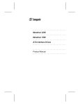
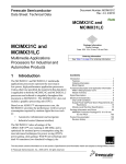
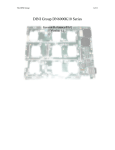
fax id: 3616
Frequently Asked Questions about the RoboClock™ Family
The following questions are frequently asked by customers who are using devices in the RoboClock™ family. The RoboClock
family consists of the RoboClock (CY7B991/2), RoboClock+ (CY7B9911), Low Voltage RoboClock (CY7B991V) and RoboClock
Jr. (CY7B9910/20). These answers will serve as an introduction for each topic. It will be indicated when a separate application
note covers the topics in more complete detail.
1.
Can I use an external divider in my feedback loop?
Yes, it is possible to use external dividers in the feedback path. However, large dividers or dividers that have an inherently
long delay, should be used cautiously. There are some constraints that should be followed. A large divider ratio can cause
the phase detector update gaps to become excessively large. This will cause the VCO to drift excessively and result in output
jitter. As a “rule of thumb” the maximum divider ratio in the feedback path should be less than 16. Larger values may be used
with some consideration.
2.
How do I achieve a 90 degree offset? How can I use an external divider to achieve a 90 degree offset independent
of frequency?
The simplest way to achieve a 90 degree phase shift is to use the programmable skew functionality of RoboClock. An exact
offset of 90 degrees is only available when the FS pin is in the HIGH state. When the FS pin is in the LOW or MID state, an
offset close to 90 degrees is still attainable. The period of the VCO is divided into different amounts of time units (tU) for each
setting of the FS pin.
•
VCOperiod = 44 tU (FS=LOW)
•
VCOperiod = 26 tU (FS=MID)
•
VCOperiod = 16 tU (FS=HIGH)
A 90 degree offset is the VCOperiod / 4. Therefore, a 90 degree offset would require an offset of:
•
FS LOW = ±11 tU for a 90 degree offset
•
FS MID = ± 6.5 tU for a 90 degree offset
•
FS HIGH = ±4 tU for a 90 degree offset
The offset of ±4 tU with FS = HIGH is achievable by simply programming the output to have a skew of ±4 tU. However, it is
not possible to get an exact offset of ±11 tU (FS=LOW) or ±6.5 tU (FS=MID). With FS in the MID position, an offset of ±6 tU
or ±7 tU is possible. This creates a phase offset of ±83 degrees (±6 tU) or ±97 degrees (±7 tU). At 50 MHz a 90-degree phase
shift is equal to ±5 ns offset. The skewed outputs are shifted by ±4.62 ns or ±5.38 ns (off by ±0.38 ns). With FS in the LOW
position, an offset of ±82 degrees (±10 tU) or ±98 degrees (±12 tU) is possible. At 30 MHz, an exact 90-degree phase shift
is equal to a ±8.33 ns offset. The skewed outputs are shifted by ±7.58 ns or ±9.09 ns (off by ±0.76 ns).
Offsets between outputs are achieved by selecting the appropriate skew taps as shown in Table 1. One of the specific outputs can be connected to FB. This establishes a zero phase reference, but the phase relationship between outputs is maintained even if another output (and skew) is used for FB.
Table 1. Skew Combinations for 90 Degree Offset
FS=HIGH
FS=MID
FS=HIGH
±4 tU, 0 tU
±6 tU, 0 tU
±6 tU, ±6 tU
±6 tU, ±2 tU
±2 tU, ±4 tU
±6 tU, ±4 tU
±2 tU, ±2 tU
±3 tU, ±3 tU
±3 tU, ±1 tU
±3 tU, ±4 tU
±6 tU, ±1 tU
It is also possible to use external dividers, as Figure 1 shows, to achieve a 90 degree offset independent of frequency. This
example utilizes a negative-edge triggered D flip-flop as an external divider. It is possible to achieve a positive or negative
Cypress Semiconductor Corporation
•
3901 North First Street
•
San Jose
• CA 95134 •
408-943-2600
June 20, 1997 – Revised June 26, 1998
Frequently Asked Questions about the RoboClock Family
90 degree phase shift independent of the frequency range. The polarity of the phase is determined by choosing either the
Q or Q output from the D flip-flop. The delay of the D flip-flop can also be compensated by adjusting the programmable skew
of the 2Q1 output of the RoboClock. It should be noted that the propagation delay of the D flip-flop is not typically controlled
nor specified. Also, the Q and Q delays may not be symmetrical. The compensating skew control of the RoboClock to account for the propagation delays may not hold over temperature, because most flip-flops exhibit significant variation while
RoboClock does not.
X MHz
L
L
L
L
M
M
M
M
FB
REF
FS
4F0
4F1
3F0
3F1
2F0
2F1
1F0
1F1
4Q0
4Q1
3Q0
3Q1
2Q0
2Q1
1Q0
1Q1
Phase=0
D
Q
–90
>
Q
+90
X MHz
4QX
3QX
2QX
Q
(+90°)
Q
(–90°)
Delay of D Flip-Flop
Figure 1. Circuit to Achieve a 90 Degree Offset
3.
What happens to the outputs when there is no REF input?
There are two scenarios that cause the output to react differently:
If REF is not connected during power up, the behavior of the output will be probabilistic. The state is dependent upon internal
circuitry that is controlled by the REF input. The output may be inactive (no output clock) or it may oscillate at the lowest
possible frequency determined by the setting of the FS pin.
If the REF input is disconnected during steady state operation, the PLL will “think” that it is running too fast and will compensate by lowering the PLL frequency. The PLL frequency will be determined by the setting of the FS pin. The final frequency
will be lower than the values stated in the data sheet. When the REF input is reconnected, the PLL will be out of phase and
frequency alignment. It will compensate by increasing the PLL frequency and will overshoot the final frequency. It will continue in a damped oscillation state until the PLL “locks” onto the FB signal. This time is called tLOCK in the data sheet.
2
Frequently Asked Questions about the RoboClock Family
4.
Is RoboClock 3.3V-compatible?
The Low Voltage RoboClock (CY7B991V) is completely 3.3V compatible. The original RoboClock (CY7B991) requires a +5V
VCC supply. However, it is possible to make the output swing to 3.3V compatible levels in the TTL RoboClock (CY7B991).
The CMOS level RoboClock (CY7B992) cannot be made 3.3V-compatible due to its design which produces rail-to-rail output
swings.
Two termination networks are shown in Figure 2, either of which make RoboClock compatible with 3.3V systems. For a more
in-depth explanation, an application note, “Using CY7B991 (RoboClock), CY7B9911 (RoboClock+) and CY7B9910 (Robo
Jr.) in 3.3V Environment” is available from the Cypress Semiconductor Corporation website (http://www.cypress.com).
+5V
+3.3V
130
82
91
130
Figure 2. Typical 50Ω Termination to 5V and 3.3V for 3.3V-Compatible RoboClock Outputs
5.
What are the jitter characteristics of RoboClock? Can you connect many RoboClocks in a cascaded configuration?
RoboClock is neither tolerant nor intolerant to jitter. It is more accurate to describe the jitter characteristics of RoboClock.
The jitter transfer characteristic is that of a second order low-pass filter with the –3d B point at approximately 1–3 MHz. The
plot can be seen in Figure 3. This plot shows typical behavior with a REF frequency of 50 MHz. There is some amplification
in a narrow band just before the roll-off (gain is greater than 0 dB) as is evidenced by the plot. This means that jitter components that fall within this range will be amplified as they pass through RoboClock. This is the reason that it is not recommended to connect more than two RoboClocks in series. Any input jitter at the peaking frequency will be amplified as it passes
through the cascaded devices.
Although this problem is evident, the recommended limit of 2 series connected RoboClocks is extremely conservative. The
band of jitter amplification changes with temperature and process variation and eventually will result in a lower cascaded
multiplication than the peak gain would predict. Thus, in real applications, jitter amplification seldom reaches a point that
output jitter causes the system to not function correctly. Also, this type of jitter is not necessarily a problem except between
systems served by multiple RoboClocks.
Figure 3. Jitter Transfer Characteristics for RoboClock
3
Frequently Asked Questions about the RoboClock Family
6.
What are the required voltage levels of a three level input? How do you model a three-level input?
Low Voltage RoboClock
VCC
VCC
VIHH
0.87*VCC
VCC – 1V
VTHH
0.53*VCC
VCC/2+500 mV
VIMM
0.47*VCC
VCC/2 – 500 mV
VTHL
0.13*VCC
1V
VILL
GND
RoboClock, RoboClock Jr,
RoboClock+
The voltage levels are V IHH, VIMM, and VILL on the data sheet. For every part in the RoboClock family, except the CY7B991V,
VIHH is between VCC – 1V and VCC. VIMM is between VCC/2 – 500 mV and VCC/2+500 mV. VILL is between 0V and 1V. The
input left floating will be held within the VIMM range. The ranges for the CY7B991V are from 0.87*VCC to VCC for VIHH, from
0.47*VCC to 0.53*VCC for VIMM, and 0.0V to 0.13*VCC for VILL. These values guarantee that the correct value will be detected. The actual thresholds (high threshold = VTHH, low threshold = VTHL) will be in-between the specified ranges, as shown
in Figure 4.
GND
Figure 4. Voltage Levels for 3-Level Inputs
The three-level inputs of the RoboClock family (excluding the CY7B991V) can be modeled by a pull-up and pull-down resistor. The internal resistor values for the three-level inputs are approximately a 25-KΩ pull-up and 25-KΩ pull-down. This is
shown in Figure 5. The corresponding I-V curve trace of the three-level input (with V CC=5.0V applied to the part) can be seen
in Figure 6. Figure 7 is the same I-V curve trace with the vertical scale zoomed out. The large change in input current at
approximately 5.7V and –0.6V are due to the ESD diodes becoming forward biased.
+5V
VTHH
25K
Three Level Input
25K
VTHL
Figure 5. Internal Pull-Up and Pull-Down Resistors of a Three-Level RoboClock Input with Threshold Detection
7.
What is the phase relationship between a /2 and /4 output?
They are negative (falling) edge aligned. In Figure 8, the falling edge of the divide by four output (3Q1), is aligned with the
falling edge of the divide by two output (4Q1). By having the falling edges of the /2 and /4 clocks aligned, the rising edges
are spaced farther in time. If it is assumed that most logic is rising edge triggered, this makes the design more robust to jit ter,
skew problems, and loading effects. This trade-off is important because the divided outputs are not skewable.
.
8.
What models are available for RoboClock?
There are HSPICE and IBIS models available on the Cypress BBS. The number for the BBS in the U.S. is (408) 943-2954,
in Japan the number is 49-810-62-2675, and in Europe the number is 49-810-62-2675. They are also available off of the
Cypress Semiconductor website (http://www.cypress.com).
4
Frequently Asked Questions about the RoboClock Family
Figure 6. I-V Curve of a Three-Level RoboClock Input (Zoomed In)
Figure 7. I-V Curve of a Three-Level RoboClock Input
5
Frequently Asked Questions about the RoboClock Family
X
MHz
FB
REF
FS
L
L
H
H
M
M
M
M
4F0
4F1
3F0
3F1
2F0
2F1
1F0
1F1
4Q0
4Q1
3Q0
3Q1
2Q0
2Q1
1Q0
1Q1
X/2
X/4
X
X
Figure 8. Frequency Divider Example
The Logic Modeling division of Synopsys also offers a wide variety of standard logic models that run on various simulation
platforms. These models (cy7b991-XX and cy7b992-XX) accurately depict the functionality of RoboClock. They can be
reached at (800) 346-6335 or at their web site:
http://www.synopsys.com/products/lm/modelDir.html.
9.
How slow can REF go in TEST mode?
There is no lower limit for the REF frequency in TEST mode. This is because in TEST mode the internal PLL is bypassed
and the input levels supplied to REF directly control the outputs. The input signal applied to REF will be seen at the outputs
with approximately a 15 to 80 ns delay. This delay can be roughly changed by using the TEST and FS level inputs. The
outputs will still function according to the function select pins. For a more in depth explanation see the, “RoboClock Family
Test Mode” application note. It is available in the Cypress Applications Handbook or off the Cypress Semiconductor website
(http://www.cypress.com).
10. What effect does slow rise and fall times on the REF input have on RoboClock operation?
A slow rise time affects the apparent t PD, which is the propagation delay (REF rise to FB rise). tPD is measured at an arbitrary
but standard 1.5V (CY7B991) or VCC/2 (CY7B992). The actual threshold voltage (VTH) of REF and FB will vary around 1.5V
(0.8v<VTH<2.0V for the CY7B991 and 1.35V<VTH<VCC – 1.35V for the CY7B992) depending upon VCC, temperature and
process variation. This change in VTH will affect tPD. For example, If input ramp rate is approximately 1 V/ns then 100mV
variation in VTH will change the apparent tPD of the REF and FB input gate by approximately 100 ps. This is normally not a
problem, since both FB and REF are threshold matched and are driven by similar edge rates.
If REF ramp rate is much longer than FB, then this “apparent” tPD variation will show up as increased (or decreased) tPD
through the RoboClock. Actually (disregarding the minimal effect of edge rate on VTH) the tPD does not change. Only the
measurement changes. The propagation delay from the time REF begins to rise, until the time when the output begins to
rise, will look like it is increasing with a slower REF rise rate or with increasing REF VTH.
Another possible effect of slow rise and fall times could be introduced jitter. This is due to the increased amount of time that
the input is near the threshold voltage. At threshold, the input buffer is much more sensitive to variations and noise.
11. Are there any power-up conditions that cause the part to misbehave?
Yes, there is. This is mentioned in NOTE 3 of the CY7B991/992 datasheet. It states, “When the FS pin is selected HIGH,
the REF input must not transition upon power-up until VCC has reached 4.3V”. As the power supply ramps-up, the PLL
“wakes-up” before the output buffers. Since the output buffers are not yet functional, there are no transitions on the FB. The
PLL “thinks” that it is not running fast enough, so it speeds up eventually reaching its maximum allowable rate as dictated
by the FS pin. Finally, VCC reaches the level where the output buffers become functional. When the FS pin is HIGH, it is
possible for the internal VCO to run faster than the outputs can follow (only undivided outputs can exhibit this behavior). Although the outputs are functional, they still can not provide the proper transitions on the FB and thus, the PLL still “thinks”
6
Frequently Asked Questions about the RoboClock Family
that it is running too slow. The end result is that the VCO locks up at its maximum rate and stays there with the outputs not
able to provide the proper transitions.
This condition is not an issue if the RoboClock is operating with the FS pin in the LOW or MID position, or if a divided output
is implemented as the feedback. If these conditions are not met then there are a few methods to ensure that this situation
does not occur.
1.Assure that REF is stable (no transitions) until VCC reaches 4.3V (point where the output buffers come on).
2.Have the part power up in TEST mode (PLL bypassed with mode in MID position).
3.Hold FS pin in LOW or MID (so that PLL will not ramp up to point that outputs can not follow) until VCC is above 4.3V.
One way to manage the FS pin is to connect it to a power-on reset. This will ensure that it is LOW until RoboClock has power.
If the power-on reset line is 5V CMOS, then it can be connected directly to the FS pin. If it is TTL then it may not be able to
drive the FS pin to its HIGH state (see question 6). It may be necessary to use a resistor network to get the proper voltage
levels on the FS pin. The implementation may look like Figure 9.
+5V
470
FS Input
1K
TTL Power-on Reset
Figure 9. FS Management Using TTL Power-on Reset
Another way to manage the FS pin is by using an RC time constant on the FS pin to make it ramp slower than VCC, holding
FS in the LOW or MID state until VCC reaches 4.3v (by using a pull-up R and pull-down C). The values of R and C can be
determined by the following:
If it takes t seconds for the VCC ramp, then you can find the RC value with the following equation:
VIMM max = VCC (1 – e^(–t/RC))
VIMM max = maximum voltage for a MID on the FS pin. From the datasheet, this is VCC/2+500 mV. Choose your R and C
values so the product equals the calculated RC value. For example, VCC=5.0V, and it takes 1ms second for the VCC ramp
(t=1 ms). R should always be chosen so that is it less than 2.5 KΩ. Then C should be approximately 0.8 micro Farads.
12. What is the output buffer current and output buffer power per output pair?
These specs (minimum and maximum values) are listed in the CY7B991/2 data sheet. They are ICCN and PD respectively.
The total output current per output pair (RoboClock has 4 pairs total) can be approximated by the following expression that
includes device current plus load current (expressed in mA):
CY7B991:
ICCN=[(4+0.11F)+[((835–3F)/Z)+(0.0022FC)]N]*1.1
CY7B992:
ICCN=[(3.5+0.17F)+[((1160–2.8F)/Z)+(0.0025FC)]N]*1.1
The total power dissipation per output pair can be approximated by the following expression that includes device power dissipation plus power dissipation due to the load circuit (expressed in mW):
CY7B991:
PD=[(22+0.61F)+[((1550-2.7F)/Z)+(0.0125FC)]N]*1.1
CY7B992
PD=[(19.25+0.94F)+[((700+6F)/Z)+(0.017FC)]N]*1.1
7
Frequently Asked Questions about the RoboClock Family
where
F=frequency in MHz
C=capacitive load in pF
Z=line impedance in Ohms
N=number of loaded outputs: 0,1 or 2
FC=F*C
For example, when using a CY7B991 with F=40 MHz, C=30 pF, Z=50Ω, and N=1 (one output loaded, the other floating), the
ICCN and PD are calculated as follows:
ICCN=
[(4+0.11*40)+[((835-3*40)/50)+(0.0022*40*30)]1]*1.1
ICCN= 27.87 mA for this specific output pair
PD=
[(22+0.61*40)+[((1550-2.7*40)/50)+(0.0125*40*30)]1]*1.1
PD=99.264 mW for this specific output pair
13. What do all the different skew values on the data sheet mean?
Skew is the difference in time between the transitions of a pair of outputs with a fixed time relationship.The skew values apply
to the skew between different outputs of the RoboClock identically loaded as specified by the datasheet. The skew depends
upon the function of the two output and in many cases the function of the rest of the outputs.
The outputs of RoboClock have been carefully designed to control delay and edge rate, in an attempt to minimize skew.
Outputs are built as pairs (XQ0 and XQ1) sharing the same drive and power supply. The outputs can also be categorized
by their function. The classes are nominal, divided, and inverted. Ideally all edges would occur at 0 ns. However, minor
variation in internal delay, output rise and fall delay, adjacent output transition direction, and edge placement (coupling) affect
the position of the output transition. The six skew specifications shown in the datasheet attempt to quantify these variations.
For further information on how to use these values to calculate the desired skew, see the application note, “Everything You
Need to Know About CY7B991/2 (RoboClock) and the RoboClock Family” in the Cypress Applications Handbook or off of
the Cypress Semiconductor home page (http://www.cypress.com).
tSKEWPR: Zero Output Matched-Pair Skew
This parameter specifies the maximum amount of skew between two outputs of the same pair (e.g., 1Q1 and 1Q0) when all
eight outputs are selected for 0tU.
tSKEW0:Zero Output Skew (All Outputs)
This parameter specifies the time between the first output edge and the last output edge of all outputs that are selected for
0tU (even if there are other outputs selected for divide-by or invert functionality but not shifted outputs).
tSKEW1:Output Skew (Rise-Rise,Fall-Fall, Same Class)
This parameter specifies the maximum amount of skew between outputs of the same output class selected for the same
output adjustment without restrictions on the placement or function of other outputs. The signals to be compared must be
same class and must be rising edge to rising edge, or falling edge to falling edge aligned. The three different output classes
are Nominal, Divided and Inverted. Nominal includes all phase variants including 0t U. Divided includes divide by four and
divide by 2 functionality. The Inverted class includes the invert function allowed on 4QX.
tSKEW2:Output Skew (Rise-Fall, Nominal-Inverted, Divided-Divided)
This parameter specifies the amount of output skew between the rising or falling edge of a Nominal output and the opposite
edge of an Inverted output. It also applies to opposite edge transitions between Divided outputs.
tSKEW3:Output Skew (Rise-Rise, Fall-Fall, Different Class)
This output skew parameter specifies the maximum same edge transition difference between different class outputs.
tSKEW4:Output Skew (Rise-Fall, Nominal-Divided, Divided-Inverted)
This parameter specifies the maximum opposite edge transition difference between different class outputs.
8
Frequently Asked Questions about the RoboClock Family
tDEV or tSKEW5: Device-to-Device Output Skew
In system design, tDEV is the amount of skew between the outputs of two devices operating in the same environment (frequency, temperature, voltage, air flow, etc.). It encompasses the worst case for all output possibilities, and therefore is a v ery
conservative number.
tSKEW5 is an outdated parameter that does not incorporate the worst case scenario, and required the addition of the applicable output-output skew value to calculate the actual device-device skew. The correct value to use when calculating skew
between any two outputs between two devices is tDEV.
tPD:Propagation Delay (REF Rise to FB Rise)
This is a measure of the misalignment between the REF rise and FB rise. It can be either positive or negative. The typical
value is 0.0 ns.
14. What is the difference between t ODCV (Output Duty Cycle Variation) and tPWH/tPWL?
tODCV is the deviation of the output from 50% duty cycle measured at 1.5V for CY7B991 and V CC/2 for CY7B992. tPWH/tPWL
is the deviation measured at the corresponding high and low thresholds (tPWH is measured at 2.0V for CY7B991 and 0.8
VCC for CY7B992, tPWL is measured at 0.8V for CY7B991 and 0.2V for CY7B992). The differences account for rise and fall
time “pulse-narrowing” from the 50% point measurement.
15. I need to estimate the reliability in my design. How many components does it contain?
For complete documentation on the reliability of the RoboClock see the yearly Reliability Report. The most commonly desired reliability information is as follows.
Technology:
BiCMOS
Number of components:
3250
Number of transistors:
2130
Number of gates:
275
Die size:
110 mils x 150 mils
Commercial Theta JC:
28 degrees C / Watt
Commercial Theta JA:
80 degrees C / Watt
Max Junction Temp.:
155 degrees C
RoboClock is a trademark of Cypress Semiconductor Corporation.
© Cypress Semiconductor Corporation, 1998. The information contained herein is subject to change without notice. Cypress Semiconductor Corporation assumes no responsibility for the use
of any circuitry other than circuitry embodied in a Cypress Semiconductor product. Nor does it convey or imply any license under patent or other rights. Cypress Semiconductor does not authorize
its products for use as critical components in life-support systems where a malfunction or failure may reasonably be expected to result in significant injury to the user. The inclusion of Cypress
Semiconductor products in life-support systems application implies that the manufacturer assumes all risk of such use and in doing so indemnifies Cypress Semiconductor against all charges.