1
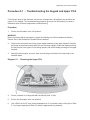
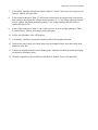
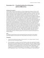
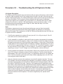
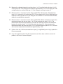
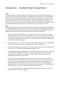
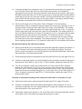
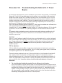
C960 Series Commercial Treadmill
Section Five - Troubleshooting Procedures
Note:
This section contains troubleshooting procedures specific to the C96X family of treadmills.
Please refer to the troubleshooting procedures in the commercial service manual (20077-101) for
additional troubleshooting procedures.
Procedure 5.1 - Troubleshooting the Keypad and Upper PCA ....................... 5-3
Procedure 5.2 - Troubleshooting the Lift System (SCR & PWM Units) .......... 5-7
Procedure 5.3 - Troubleshooting the Lift System (i Units) .............................. 5-11
Procedure 5.4 - Troubleshooting the Speed Sensor........................................ 5-15
Procedure 5.5 - Troubleshooting Hand Held Heart Rate ................................. 5-17
Procedure 5.6 - Troubleshooting the External A.C. Power Source ................ 5-21
C960 Series Commercial Treadmill
Procedure 5.1 - Troubleshooting the Keypad and Upper PCA
If the function keys on the electronic console are unresponsive, the problem may be either the
upper PCA or keypad. This troubleshooting procedure gives you the information you need to
determine which of these components is malfunctioning.
Procedure
1.
Set the circuit breaker in the ìoffî position.
WARNING
Before continuing with this procedure, review the Warning and Caution statements listed in
Section One of the Residential Treadmill Service Manual.
2.
Remove the screws that secure the upper display assembly to the upper handrail. Carefully,
pull some excess interconnect cable out from the targa upright. Rotate the display housing,
so that the rear of the upper PCA is facing upward, and set the display housing on the upper
handrail.
3.
Attach the wrist strap to your arm, then connect the ground lead of the wrist strap to the
treadmill frame.
Diagram 5.1 - Removing the Upper PCA
4.
Set the voltmeter to a range that will conveniently read +6 Vdc.
5.
Set the circuit breaker in the ìonî position.
6.
Use a DVM, set for DC volts, and read between pin 5 of J4 and the each of the pins in Table
5.1 (no keys pressed) and Table 5.2 (with the appropriate key pressed)...
C960 Series Commercial Treadmill
Diagram 5.2 - Upper PCA Component Layout
Table 5.1 - Voltage Test Points (Function Keys Not Pressed)
PLACE THE POSITIVE LEAD OF THE
VOLTMETER ON...
Pin 1 of J4
Pin 2 of J4
Pin 3 of J4
Pin 4 of J4
Pin 6 of J4
Pin 7 of J4
Pin 8 of J4
Pin 9 of J4
Pin 4 of J2
Pin 5 of J2
Pin 6 of J2
THE VOLTMETER SHOULD
READ...
5 Vdc ± 500 mVdc
5 Vdc ± 500 mVdc
5 Vdc ± 500 mVdc
5 Vdc ± 500 mVdc
5 Vdc ± 500 mVdc
5 Vdc ± 500 mVdc
5 Vdc ± 500 mVdc
5 Vdc ± 500 mVdc
5 Vdc ± 500 mVdc
5 Vdc ± 500 mVdc
5 Vdc ± 500 mVdc
Table 5.2 - Voltage Test Points (Function Keys Pressed)
Place the positive lead
of the voltmeter on...
Pin 1 of J4
Pin 2 of J4
Pin 3 of J4
Pin 4 of J4
Pin 6 of J4
Pin 7 of J4
Pin 8 of J4
Pin 9 of J4
Pin 4 of J2
Pin 6 of J2
Pin 7 of J2
At the electronic
console, press...
Left CHANGE key
STOP key
SPEED key
SPEED key
QUICK START key
ENTER key
Right CHANGE key
Center CHANGE key
RESET key
INCLINE key
INCLINE key
The voltmeter
should read between...
0 Vdc and 350 mVdc
0 Vdc and 350 mVdc
0 Vdc and 350 mVdc
0 Vdc and 350 mVdc
0 Vdc and 350 mVdc
0 Vdc and 350 mVdc
0 Vdc and 350 mVdc
0 Vdc and 350 mVdc
0 Vdc and 350 mVdc
0 Vdc and 350 mVdc
0 Vdc and 350 mVdc
C960 Series Commercial Treadmill
7.
If the voltage readings match those listed in Tables 5.1 and 5.2 and one or more keys do not
function, replace the upper PCA.
8.
If the voltage readings in Table 5.1 are incorrect, disconnect the keypad cable from the key
pad connector and repeat the voltage measurements in 5.1. If the voltage readings are now
correct, replace the display housing (keypad). If the voltage readings are still incorrect,
replace the upper PCA.
9.
If the voltage readings in Table 5.1 are correct and one or more voltage readings in Table
5.2 are incorrect, replace the display housing (keypad).
10. Set the circuit breaker in the ìoffî position.
11. If necessary, carefully re-connect the keypad cable to the keypad connector.
12. Remove the ground lead of the wrist strap from the treadmill frame, then remove the wrist
strap from your arm.
13. Position the display enclosure on the display plate. Install the screws that secure the display
enclosure to the display plate.
14. Check the operation of the treadmill as described in Section Three of this appendix.
C960 Series Commercial Treadmill
Procedure 5.2 - Troubleshooting the Lift System
(SCR & PWM Units)
Lift System Description:
The lift system on these units consists of an AC line voltage driven lift motor (120 Vac or 240
Vac), a hall effect rotation sensor and three position location switches. The lift system orients
itself by locating the zero sense switch when the treadmill is powered up. When the zero sense
switch is activated the system recognizes that physical position as 0% incline. If the zero sense
switch is activated when the treadmill is powered up, the system proceeds directly into the
normal program mode. If the zero sense switch is not activated when the treadmill is powered up,
the system performs a self calibration procedure. The purpose of the self calibration procedure is
to locate the zero sense switch (0% incline). The user will be prompted to press any key to
commence the lift calibration. The treadmill will go up 4%, because the lowest the treadmill could
have been at power up is -3%. If the treadmill does not locate the zero sense switch by going up
4%, it will stop and then go down until it activates the zero sense switch. The system will then
proceed to the normal program mode. Once the 0% lift position has been located, the system
tracks any subsequent lift operations by counting motor revolutions. A hall effect sensor is
mounted on a bracket that is next to a hub that is attached to the lift motor shaft. As the lift motors
operates, a magnet mounted in the hub, passes the hall effect sensor once per motor revolution.
The hall effect sensor send one pulse to the lift control system per revolution. The system knows
how far the lift travels per revolution and by counting revolutions (hall effect sensor pulses),
knows the current lift position. The other two position switches (upper and lower limit) do not
come into play during normal operation. If either switch is activated it means that the lift has
moved beyond itís normal range of motion. When either limit switch is activated, power is
removed from the lift motor. Removing power from the lift motor, protects the lift system from
physical damage.
Note:
All resistance measurements must be performed with power removed from the treadmill.
Performing resistance measurements with voltage applied may damage your ohmmeter.
Procedure
1.
If the lift motor operates but creates a lift error (error 40, 41 or 43) go to step 8. If the lift
motor will not move continue with step 2.
2.
Put the treadmill in a condition in which the lift motor is ready to be operated (for example,
quick start into the manual program). Using an AC voltmeter, monitor the voltage across the
lift capacitor and press one of the incline keys. Approximately 1.4 times the AC input voltage
should appear on the lift capacitor when an incline key is pressed. Approximately 170 Vac
on a 120 Vac unit or approximately 340 Vac on a 240 Vac unit. The actual lift capacitor
voltage will vary with the AC input voltage. If AC line voltage or 1.4 times line voltage is on
the lift capacitor go to step 6. If no AC voltage is on the lift capacitor, continue with step 3.
C960 Series Commercial Treadmill
3.
Set the treadmill circuit breaker in the ìoffî position. Remove the 2 amp lift fuse (F2) from the
lower PCA. Using an ohmmeter, measure the fuse resistance. The fuse should measure
approximately 1W or less. If the fuse is open (ï) or significantly higher than 1W, replace the
fuse. If the fuse was bad, perform the test in step 4 before applying power to the lift. If the
fuse was good continue with step 5.
4.
Using an ohmmeter, measure the resistance across the lift capacitor terminals. The Lower
PCA resistance should be extremely high (megohms), the capacitor resistance should be
extremely high (megohms) and the lift motor winding should read approximately 34W (120
Vac units) or 122W (240 Vac units). Therefore, if the measurement is significantly lower
than 34W or 122W, disconnect both red leads from the lift capacitor. Measure the resistance
between the black leads on the lift capacitor and red lead to the lower PCA. If it measures
significantly low, replace the lower PCA. Measure the resistance between the black leads on
the lift capacitor and red lead to the lift motor. If it measures significantly low, replace the lift
motor. Measure the resistance between the black leads on the lift capacitor and other
terminal of the lift capacitor. If it measures significantly low, replace the lift capacitor.
5.
At this point the lift fuse is good, but there is no AC voltage on the lift capacitor when the lift
is actuated. There are three potential causes for this condition. They are lower PCA, ribbon
cable or upper PCA. There are no good means of troubleshooting these components other
than substituting known good components. Replace only one component at a time. If the
component that you replaced does not correct the problem, replace the original component.
Try substituting the lower PCA first, the ribbon cable second and the upper PCA third. If you
have performed all of the above procedures and have been unable to correct the problem,
call Precor Customer Support.
6.
Using an ohmmeter, measure the resistance across the lift capacitor terminals. The lower
PCA resistance should be extremely high (megohms), the capacitor resistance should be
extremely high (megohms) and the lift motor winding should read approximately 34W or
122W. If it measures significantly high or open (ï), replace the lift motor.
7.
If the resistance measurement in step 6 was approximately 34W (120 VAC units) or 122W
(240 VAC units), replace the lift capacitor. If you have performed all of the above procedures
and have been unable to correct the problem, call Precor Customer Support.
8.
Typically, when the lift is able to physically move but causes a lift error, the problem is in the
lift position identification system (rotation sensor and zero sense switch).
9.
Connect a DC voltmeter between the white wire (term. 2 of J3) and the red wire (term. 4 of
J3) on the lower PCA. Set the treadmill circuit breaker in the ìonî position and slowly rotate
the hub at the bottom of the lift motor by hand. The DC voltmeter should read approximately
0 Vdc when the magnet in the hub is not near the hall effect sensor and approximately 5
VDC when the magnet is near the hall effect sensor. If the voltage switches between 0 and
5 Vdc as the magnet passes the hall effect sensor continue with step 11.
C960 Series Commercial Treadmill
10. Measure the voltage between the red wire (term. 4 of J3) and the black wire (term 1 of J3).
The voltage should read a constant 5 Vdc. If the voltage is 0 or significantly lower than 5
Vdc, disconnect the rotation sensor connector from the lower PCA. Measure the voltage
between the red wire (term. 4 of J3) and the black wire (term 1 of J3) on the lower PCA. If
the voltage is still 0 Vdc or significantly low, replace the lower PCA. If the voltage is now
correct, replace the hall effect sensor.
Note:
If possible set the lift in a position that does not operate the zero sense switch. The zero sense
switch may be operated by hand to perform the tests in step 11.
11. At this point the hall effect sensor is functioning normally, but lift errors occur. With a DC
voltmeter measure the voltage across the zero sense (center) switch. It should measure
approximately 0 Vdc when the switch is not operated and approximately 5 Vdc when the
switch is operated. If the operated voltage is 0 Vdc or significantly low, remove both blue
wires from the zero sense switch. Measure the voltage between the two blue wires. If the
voltage is now correct replace the zero sense switch. If the voltage is still O Vdc or
significantly low, replace the lower PCA.
12. At this point the hall effect sensor and the zero sense switch are functioning normally, but lift
errors occur. There are three potential causes for this condition. They are lower PCA, ribbon
cable or upper PCA. There are no good means of troubleshooting these components other
than substituting known good components. Replace only one component at a time. If the
component that you replaced does not correct the problem, replace the original component.
Try substituting the lower PCA first, the ribbon cable second and the upper PCA third. If you
have performed all of the above procedures and have been unable to correct the problem,
call Precor Customer Support.
C960 Series Commercial Treadmill
Procedure 5.3 - Troubleshooting the Lift System (i Units)
Lift System Description:
The C962i and C964i treadmills were manufactured with two types of lift systems. Units built prior
to April 20, 2000 consisted of an AC line voltage driven lift motor (120 Vac or 240 Vac) and an
external 10 KW potentiometer. The 10KW potentiometer rotates as the lift operates and indicates
the current lift position. The lift system is factory calibrated, but will require re-calibration
whenever the upper PCA is replaced (refer to procedure 4.2). Units built after April 19, 2000,
utilized a lift motor with an internal 1 KW potentiometer. Use the procedure in steps 1-14 for
trpubleshooting units manufactured prior to April 20, 2000. Start with step 15 for units
manufactured after April 19, 2000.
Note:
All resistance measurements must be performed with power removed from the treadmill.
Performing resistances measurements with voltage applied may damage your ohmmeter.
Whenever the upper PCA is replaced on a C962i or C964i manufactured prior April 20, 2000, the
lift system must be re-calibrated.
1.
If the lift motor operates but creates a lift error (error 40, 41 or 42) go to step 8. If the lift
motor will not move continue with step 2.
2.
Put the treadmill in a condition in which the lift motor is ready to be operated (for example,
quick start into the manual program). Using an AC voltmeter, monitor the voltage across the
lift capacitor and press one of the incline keys. Approximately 1.4 times the AC input voltage
should appear on the lift capacitor when a incline key is pressed. Approximately 170 Vac on
a 120 Vac unit or approximately 340 Vac on a 240 Vac unit. The actual lift capacitor voltage
will vary with the AC input voltage. If AC line voltage or 1.4 times line voltage is on the lift
capacitor go to step 6. If no AC voltage is on the lift capacitor, continue with step 3.
3.
Set the treadmill circuit breaker in the ìoffî position. Remove the 2 amp lift fuse (F2) from the
lower PCA. Using an ohmmeter, measure the fuse resistance. The fuse should measure
approximately 1W or less. If the fuse is open (ï) or significantly higher than 1W, replace the
fuse. If the fuse was bad, perform the test in step 4 before applying power to the lift. If the
fuse was good continue with step 5.
4.
Using an ohmmeter, measure the resistance across the lift capacitor terminals. The lower
PCA resistance should be extremely high (megohms), the capacitor resistance should be
extremely high (megohms) and the lift motor winding should read approximately 34W (120
Vac units) or 122W (240 Vac units). Therefore, if the measurement is significantly lower
than 34W or 122W, disconnect both red leads from the lift capacitor. Measure the resistance
between the black leads on the lift capacitor and red lead to the lower PCA. If it measures
significantly low, replace the lower logic/lift PCA. Measure the resistance between the black
leads on the lift capacitor and red lead to the lift motor. If it measures significantly low,
replace the lift motor. Measure the resistance between the black leads on the lift capacitor
and other terminal of the lift capacitor. If it measures significantly low, replace the lift
capacitor.
C960 Series Commercial Treadmill
5.
At this point the lift fuse is good, but there is no AC voltage on the lift capacitor when the lift
is actuated. There are three potential causes for this condition. They are lower logic/lift PCA,
ribbon cable or upper PCA. There are no good means of troubleshooting these components
other than substituting known good components. Replace only one component at a time. If
the component that you replaced does not correct the problem, replace the original
component. Try substituting the lower PCA first, the ribbon cable second and the upper PCA
third.
6.
If you have performed all of the above procedures and have been unable to correct the
problem, call Precor Customer Support.
7.
Using an ohmmeter, measure the resistance across the lift capacitor terminals. The lower
logic/lift PCA resistance should be extremely high (megohms), the capacitor resistance
should be extremely high (megohms) and the lift motor winding should read approximately
34W or 122W. If it measures significantly high or open (ï), replace the lift motor.
8.
If the resistance measurement in step 6 was approximately 34W (120 VAC units) or 122W
(240 VAC units), replace the lift capacitor. If you have performed all of the above procedures
and have been unable to correct the problem, call Precor Customer Support.
9.
Typically, when the lift is able to physically move but causes a lift error, the problem is in the
lift position identification system (lift potentiometer or lift calibration).
10. Measure the voltage between the red wire (term. 1 of J1) and the black wire (term 3 of J1)
on the lower PCA. The voltage should measure approximately 5 Vdc. If the voltage is 0 Vdc
or significantly low, continue with step 11. If the voltage is correct go to step 12.
11. Disconnect the J1 connector from the lower logic/lift PCA. Measure the voltage between
term.1 of J1 and term 3 of J1on the lower PCA. If the voltage is still 0 Vdc or significantly low
replace the lower logic/lift PCA. If the voltage is correct with the J1 connector disconnected,
replace the potentiometer assembly.
12. Disconnect the J1 connector from the lower logic/lift PCA. With an ohmmeter, measure the
resistance between the red wire (term. 1 of J1) and the black wire (term 3 of J1). The
measurement should be approximately 10KW. With an ohmmeter, measure the resistance
between the red wire (term. 1 of J1) and the white wire (term 2 of J1)and measure the
resistance between the white wire (term. 2 of J1) and the black wire (term 3 of J1). The sum
of the last two measurements should total approximately 10 KW.
13. If either of the two 10 KW measurements are open (ï) or significantly low or high, replace the
potentiometer assembly.
14. If you have performed all of the above procedures and have been unable to correct the
problem, call Precor Customer Support.
15. If the lift motor operates but creates a lift error (error 40, 41 or 42) go to step 22. If the lift
motor will not move continue with step 2.
C960 Series Commercial Treadmill
16. Put the treadmill in a condition in which the lift motor is ready to be operated (for example,
quick start into the manual program). Using an AC voltmeter, monitor the voltage across the
lift capacitor and press one of the incline keys. Approximately 1.4 times the AC input voltage
should appear on the lift capacitor when a incline key is pressed. Approximately 170 Vac on
a 120 Vac unit or approximately 340 Vac on a 240 Vac unit. The actual lift capacitor voltage
will vary with the AC input voltage. If AC line voltage or 1.4 times line voltage is on the lift
capacitor go to step 20. If no AC voltage is on the lift capacitor, continue with step 17.
17. Set the treadmill circuit breaker in the ìoffî position. Remove the 2 amp lift fuse (F2) from the
lower PCA. Using an ohmmeter, measure the fuse resistance. The fuse should measure
approximately 1W or less. If the fuse is open (ï) or significantly higher than 1W, replace the
fuse. If the fuse was bad, perform the test in step 18 before applying power to the lift. If the
fuse was good continue with step 19.
18. Using an ohmmeter, measure the resistance across the lift capacitor terminals. The lower
PCA resistance should be extremely high (megohms), the capacitor resistance should be
extremely high (megohms) and the lift motor winding should read approximately 32W (120
Vac units) or 115W (240 Vac units). Therefore, if the measurement is significantly lower
than 32W or 115W, disconnect both red leads from the lift capacitor. Measure the resistance
between the black leads on the lift capacitor and red lead to the lower PCA. If it measures
significantly low, replace the lower logic/lift PCA. Measure the resistance between the black
leads on the lift capacitor and red lead to the lift motor. If it measures significantly low,
replace the lift motor. Measure the resistance between the black leads on the lift capacitor
and other terminal of the lift capacitor. If it measures significantly low, replace the lift
capacitor.
19. At this point the lift fuse is good, but there is no AC voltage on the lift capacitor when the lift
is actuated. There are three potential causes for this condition. They are lower logic/lift PCA,
ribbon cable or upper PCA. There are no good means of troubleshooting these components
other than substituting known good components. Replace only one component at a time. If
the component that you replaced does not correct the problem, replace the original
component. Try substituting the lower PCA first, the ribbon cable second and the upper PCA
third.
20. If you have performed all of the above procedures and have been unable to correct the
problem, call Precor Customer Support.
21. Using an ohmmeter, measure the resistance across the lift capacitor terminals. The lower
logic/lift PCA resistance should be extremely high (megohms), the capacitor resistance
should be extremely high (megohms) and the lift motor winding should read approximately
32W or 115W. If it measures significantly high or open (ï), replace the lift motor.
22. If the resistance measurement in step 6 was approximately 32W (120 VAC units) or 115W
(240 VAC units), replace the lift capacitor. If you have performed all of the above procedures
and have been unable to correct the problem, call Precor Customer Support.
23. Typically, when the lift is able to physically move but causes a lift error, the problem is in the
lift position identification system (lift potentiometer or lift calibration).
C960 Series Commercial Treadmill
24. Measure the voltage between the red wire (term. 1 of J1) and the black wire (term 3 of J1)
on the lower PCA. The voltage should measure approximately 5 Vdc. If the voltage is 0 Vdc
or significantly low, continue with step 11. If the voltage is correct go to step 12.
25. Disconnect the J1 connector from the lower logic/lift PCA. Measure the voltage between
term.1 of J1 and term 3 of J1on the lower PCA. If the voltage is still 0 Vdc or significantly low
replace the lower logic/lift PCA. If the voltage is correct with the J1 connector disconnected,
replace the potentiometer assembly.
26. Disconnect the J1 connector from the lower logic/lift PCA. With an ohmmeter, measure the
resistance between the red wire (term. 1 of J1) and the black wire (term 3 of J1). The
measurement should be approximately 1KW. With an ohmmeter, measure the resistance
between the red wire (term. 1 of J1) and the white wire (term 2 of J1)and measure the
resistance between the white wire (term. 2 of J1) and the black wire (term 3 of J1). The sum
of the last two measurements should total approximately 1 KW.
27. If either of the two 1 KW measurements are open (ï) or significantly low or high, replace the
lift motor assembly.
28. If you have performed all of the above procedures and have been unable to correct the
problem, call Precor Customer Support.
C960 Series Commercial Treadmill
Procedure 5.4 - Troubleshooting the Speed Sensor
Note:
The speed sensor is a hall effect sensor that emits a pulse when a flywheel lobe passes it. The
speed control circuit processes the pulse train emitted by the speed sensor. The speed sensor
signal is a real time representation of the operating speed of the treadmill. The speed control
circuit compares the real time speed (speed sensor output) with the speed that it expects the
treadmill to be operating at and acts accordingly to control treadmill speed or initiate an error
code sequence, if necessary. Typically, if a problem exists with the speed sensor the drive motor
will operate (perhaps only briefly) before a speed related error occurs (errors 20-26).
Note:
Some speed sensor have red, black and white wires and some have red, black and green wires.
The following procedures will assume red, black and white wires. If the speed sensor on the unit
under test has red black and green wires, perform your test procedures using the green wire
instead of the white wire. The white and green wires serve the same function.
1.
Set the treadmill circuit breaker in the ìonî position. Using a DC voltmeter, measure the
voltage between terminal 1 of J5 (red wire) and terminal 3 of J5 (white wire) on the lower
PCA. Slowly, rotate the drive motor flywheel. The voltage should read approximately 5 Vdc
as a flywheel lobe passes the speed sensor and approximately 0 Vdc when a flywheel lobe
is not in front of the speed sensor.
2.
If the voltage in step 1 is correct, go to step 5. If the voltage in step 1 is 0 Vdc or significantly
low when a flywheel lobe passes the speed sensor, continue with step 3.
3.
Measure the voltage between terminal 1 of J5 (red wire) and terminal 4 of J5 (black wire) on
the lower PCA. The voltage should read approximately 5 Vdc.
4.
If the voltage is missing or significantly low, disconnect the speed sensor plug from the lower
PCA. Measure the voltage between pins 1 & 4 of the J5 plug on the lower PCA. If the
voltage is approximately 5 Vdc, replace the speed sensor. If the voltage is missing or
significantly low, replace the lower PCA.
5.
At this point the speed sensor output is good, but speed error occur. There are three
potential causes for this condition. They are ribbon cable, upper PCA or lower PCA. There
are no good means of troubleshooting these components other than substituting known
good components. Replace only one component at a time. If the component that you
replaced does not correct the problem, replace the original component. Try substituting the
ribbon cable first, the upper PCA second and the lower PCA third.
6.
If you have performed all of the above procedures and have been unable to correct the
problem, call Precor Customer Support.
C960 Series Commercial Treadmill
Procedure 5.5 - Troubleshooting Hand Held Heart Rate
Circuit Description
The hand held heart rate system is actually a dual system, that is, it can accept a heart rate
signal from either the hand held heart rate contacts on the unitís handlebar or from a Polar heart
rate chest strap transmitter. Refer to Diagram 5.3 and verify that no jumpers are equipped on
J13, J14, J15 or J16. Also, verify that there is a jumper equipped on the internal chest strap
setting. The internal chest strap setting is the two left hand pins on the three pin connector as
shown below in Diagram 5.3. These settings allow the heart rate system to operate on the
internal chest strap receiver with the chest strap heart rate priority. That is, if both a chest strap
and hand heart rate signal is being received, the system will accept the chest strap signal and
ignore the hand held signal. If a chest strap signal is not being received, the system will accept
the hand held signal.
Note:
There are four typical failure modes for the hand held/chest strap heart rate system. They are:
1 - hand held is normal - no chest strap reading; 2 - no hand held reading - chest strap normal;
3 - no hand held or chest strap reading; 4 - constant or intermittent readings when neither hand
held or chest strap are in use.
Diagram 5.3 - Hand held/chest strap heart rate PCA
J13
HR Output
J14
J15
J16
5 Vdc
Gnd
Lower Right
Internal Chest
Strap Setting
o o o
Upper Right
Upper Left
Lower Left
Normal hand held reading - No chest strap reading
1.
Set the on/off switch in the ìonî position and access the diagnostic program (Procedure 2.1
or 2.2). Advance to the heart rate display portion of the diagnostic program. Verify that a
chest strap signal is not being accepted with either a Polar heart rate test transmitter or a
known good chest strap transmitter. If this reading is good, skip to step 3.
2.
Using a Polar heart rate test receiver, verify the operation of the chest strap transmitter
furnished with the unit. If the Polar heart rate test receiver does not receive a signal, replace
the chest strap transmitter.
C960 Series Commercial Treadmill
3.
Set the on/off switch in the ìoffî position and remove the display housing.
4.
Verify the internal chest strap setting is set as shown in Diagram 5.3. Verify that a ferrite
bead is installed on the heart rate PCA to upper PCA cable.
5.
If the above procedures did not correct the problem, replace the heart rate PCA.
No hand held reading - Normal chest strap reading
6.
Set the on/off switch in the ìonî position and access the diagnostic program (Procedure 2.1
or 2.2). Advance to the heart rate display portion of the diagnostic program. Verify that a
hand held signal is not being accepted by firmly grasping both the right and left hand held
contacts on the handlebars. Cover as much of the contact surface area with your hands as
possible (without moving your hands), you should receive a heart rate reading within ten
seconds.
7.
If a hand held signal is not being accepted, set the on/off switch in the off position.
8.
Temporarily, install a spare jumper on J14 of the heart rate PCA (hand held priority). Set the
on/off switch in the ìonî position and repeat the procedure in step 6.
9.
If the hand held signal is now being accept, something in the near vicinity is radiating RF
(radio frequency) energy that is being received by the chest strap portion of the heart rate
PCA. Disabling the chest strap signal proves that it is radiated energy that is causing the
problem.
10.
If a hand held signal still not being accepted, skip to step 13.
11. The source of the radiated energy must be determined and relocated so that it no longer
affects the heart rate PCA. Televisions, cell phones, Cardio-theatre receivers, etc. are
possible sources of radiated energy.
12. Set the on/off switch in the ìoffî position, and remove the temporary jumper from J14 of the
heart rate PCA. Re-locate all potential sources of radiation. Set the on/off switch in the ìonî
position and repeat the procedure in step 6.
13. Set the on/off switch in the ìonî position and access the diagnostic program (Procedure 2.1
or 2.2). Advance to the heart rate display portion of the diagnostic program. Verify that a
hand held signal is not being accepted by firmly grasping both the right and left hand held
contacts with the opposite hands, right hand on the left handlebar contacts and left hand on
the right handlebar contacts. Cover as much of the contact surface area with your hands as
possible, you should receive a heart rate reading within ten seconds. If a hand held signal is
still not being accepted, skip to step 15.
C960 Series Commercial Treadmill
14. If a hand held signal was accepted in step 13, the hand held contact wiring is reversed. The
end of the wire harness that connects to the hand held contacts in the handlebar is
segregated into two groups. One group has blue shrink wrap around it and the other group
has black shrink wrap around it. The ìblueî group must go to the right hand contacts and the
ìblackî group must go to the left hand contacts. In both groups the black wire must go to the
lower contact and the red wire must go to the upper contact. If necessary, rewire the hand
held contacts as described above and test as described in step 6.
15. Set the on/off switch in the ìoffî position. Refer to Diagram 5.3 for the following
measurements. With an ohmmeter measure between the ìlower right contactî pin on the J1
connector and the lower right hand held heart rate contact on the handlebar. The reading
should be 1 W or less. Measure between the ìupper right contactî pin on the J1 connector
and the upper right hand held heart rate contact on the handlebar. The reading should be 1
W or less. Measure between the ìupper left contactî pin on the J1 connector and the upper
left hand held heart rate contact on the handlebar. The reading should be 1 W or less.
Measure between the ìlower left contactî pin on the J1 connector and the lower left hand
held heart rate contact on the handlebar. The reading should be 1 W or less. If any of the
above readings are greater than 1 W, replace the heart rate PCA to handlebar wire harness.
No hand held reading - No chest strap reading
16. Set the on/off switch in the ìonî position and access the diagnostic program (Procedure 2.1
or 2.2). Advance to the heart rate display portion of the diagnostic program. Verify that
neither a chest strap signal or a hand held signal is being accepted with either a heart rate
test transmitter or a chest strap transmitter.
17. Check the plug/connector connections on both the heart rate PCA (J4), and upper PCA (J1).
18. If neither a chest strap signal or a hand held signal is being accepted, measure between the
ìgroundî and ì5 Vdcî pins on J4 for 5 Vdc. If 5 Vdc is present, replace the heart rate PCA.
19. If 5 Vdc is not present, remove the connector from J4 of the heart rate PCA. Measure
between the ìgroundî and ì5 Vdcî pins of the connector (just removed from the heart rate
PCA) for 5 Vdc. If 5 Vdc is present, replace the heart rate PCA. If the 5 Vdc is not present,
measure between the corresponding pins of J1 on the upper PCA (red and black wires). If 5
Vdc is not present replace the upper PCA. If 5 Vdc is present, replace the upper PCA to
heart rate PCA cable.
Constant or intermittent readings when neither the hand held or chest strap is in use
20. Verify that a ferrite core is clamped around the heart rate PCA to upper PCA cable.
21. Constant or intermittent heart rate readings when neither heart rate system is in use is
caused by something in the near vicinity radiating RF energy that is being received by the
chest strap portion of the heart rate PCA.
22. Temporarily, install a spare jumper on J14 of the heart rate PCA (hand held priority). Set the
on/off switch in the ìonî position and repeat the procedure in step 6.
C960 Series Commercial Treadmill
23. If the hand held signal is now being accept, something in the near vicinity is radiating RF
energy that is being received by the chest strap portion of the heart rate PCA. Disabling the
chest strap signal proves that it is radiated energy that is causing the problem.
24. The source of the radiated energy must be determined and relocated so that it no longer
affects the heart rate PCA. Televisions, cell phones, Cardio-theatre receivers, etc. are
possible sources of radiated energy.
25. Set the on/off switch in the ìoffî position, and remove the spare jumper from J14 of the heart
rate PCA. Re-locate all potential sources of radiation. Set the on/off switch in the ìonî
position and repeat the procedure in step 6.
C960 Series Commercial Treadmill
Procedure 5.6 - Troubleshooting the External A.C. Power
Source
It is extremely important that any Precor treadmill be connected to and operated on a dedicated
20 amp A.C. circuit. A 20 amp dedicated circuit is defined as: a circuit fed by a 20 amp circuit
breaker that feeds a single load. A treadmill operating from a non-dedicated circuit or a circuit
breaker of less than 20 amps capacity will not have the necessary power available to operate
normally under higher load conditions. The lack of available power can cause any number of
symptoms ranging from numerous intermittent (seemingly inexplicable) error conditions, poor
speed control, or tripping the house circuit breaker.
If any of the above symptoms exist the external A.C. circuit must be checked and confirmed to be
a 20 amp dedicated circuit before troubleshooting the treadmill.
In addition the A.C. voltage must be checked. Nominal A.C. operating voltage on 120 Vac circuits
is 105 Vac to 120 Vac. Nominal A.C. operating voltage on 240 Vac circuits is 208 Vac to 240
Vac.
For operator safety considerations and to minimize electrostatic discharge conditions the A.C.
frame ground continuity must also be verified to be a low resistance connection to the A.C.
distribution ground bar.
Important
If the A.C. circuit feeding a treadmill is found to be a non-dedicated circuit or a circuit equipped
with a circuit breaker with a capacity of less than 20 amps, the A.C. circuit must be corrected to
be a 20 amp dedicated circuit before any reliable troubleshooting can be performed on the
treadmill. More importantly, a non-dedicated circuit may constitute a safety hazard to the
treadmill operator.
120 Vac Systems
120 Vac distribution systems utilize a single pole circuit breaker (hot lead) and a neutral lead
connected to a common neutral (ground) bar. The A.C. safety ground (green wire) is connected
to a separate ground bar in the distribution system.
The most common problems found are (1) the circuit is fed by a circuit breaker of less than 20
amp capacity, (2) the circuit breaker correctly feeds a single A.C. outlet but the neutral is
common between several A.C. outlets and (3) both the hot and neutral leads feed several A.C.
outlets. The appropriate correction action or actions (see below) must be followed if any of the
above conditions exist. Corrective actions should only be undertaken by a licensed
electrician.
1.
The circuit breaker feeding the treadmill is not a 20 amp circuit breaker.
If the circuit breaker is greater than 20 amps, the circuit breaker should be replaced with a
20 amp circuit breaker. If the circuit breaker is less than 20 amps the circuit breaker must be
replaced with a 20 amp circuit breaker and the wiring from the A.C. distribution must be
capable of safely handing 20 amps. If the A.C. wiring is under sized, it must be replaced
with wire capable of safely handling 20 amps. Please, refer to local electrical codes when
determining the appropriate wire size for a 20 amp circuit.
C960 Series Commercial Treadmill
2.
The circuit breaker correctly feeds a single A.C. outlet but the neutral is common
between several A.C. outlets.
The common neutral lead must be removed from treadmillís A.C. outlet and a new neutral
lead from the treadmillís A.C. outlet to the A.C. neutral distribution bar must be added.
3.
Both the hot and neutral leads feed several A.C. outlets.
Both the common neutral and hot leads must be removed from treadmillís A.C. outlet and a
new neutral lead and hot lead from the treadmillís A.C. outlet to the A.C. neutral distribution
bar and circuit breaker must be added.
240 Vac Systems
240 Vac distribution systems utilize a double pole circuit breaker (two hot leads) The A.C. safety
ground (green wire) is connected to a ground bar in the distribution system.
The most common problems found are (1) the circuit is fed by a circuit breaker of less than 20
amp capacity and (2) both the hot leads feed several A.C. outlets. The appropriate correction
action or actions (see below) must be followed if any of the above conditions exist. Corrective
actions should only be undertaken by a licensed electrician.
1.
The circuit breaker feeding the treadmill is not a 20 amp circuit breaker.
If the circuit breaker is greater than 20 amps, the circuit breaker should be replaced with a
20 amp circuit breaker. If the circuit breaker is less than 20 amps the circuit breaker must be
replaced with a 20 amp circuit breaker and the wiring from the A.C. distribution must be
capable of safely handing 20 amps. If the A.C. wiring is under sized, it must be replaced
with wire capable of safely handling 20 amps. Please, refer to local electrical codes when
determining the appropriate wire size for a 20 amp circuit.
2.
Both the hot leads feed several A.C. outlets.
Both hot leads must be removed from treadmillís A.C. outlet and two new hot leads from the
treadmillís A.C. outlet to the circuit breaker must be added.
A licensed electrician may use the followings hints to determine if an A.C. service is dedicated.
1.
If, on a 120 Vac system, the A.C. distribution panel contains more circuit breakers than
neutral leads, the system has shared neutral leads and is not dedicated.
2.
If an A.C. outlet (120 or 240 Vac) has multiple hot and/or neutral leads, it is not a dedicated.
3.
If either of the above conditions exist, the system is not dedicated. However, absence of the
above conditions does not necessarily mean that the system is dedicated. If any doubt
exists about A.C. systems dedication, point to point tracing of the A.C. wiring may be the
only way to prove system dedication.