1
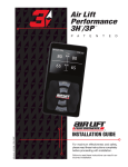
™
Kit 25655
Single Gauge
Controller
MN-342 • (031107) • ECR 7119
Cover image
may not depict
actual kit.
INSTALLATION GUIDE
For maximum effectiveness and safety,
please read these instructions completely
before proceeding with installation.
Failure to read these instructions can result in an
incorrect installation.
TABLE OF CONTENTS
Introduction . . . . . . . . . . . . . . . . . . . . . . . . . . . . . . . . . . . 2
Important Safety Notice . . . . . . . . . . . . . . . . . . . . . . . . . . . . . . . . . . . . . . . . . . . . . 2
Notation Explanation . . . . . . . . . . . . . . . . . . . . . . . . . . . . . . . . . . . . . . . . . . . . . . . . 2
Installation Diagram . . . . . . . . . . . . . . . . . . . . . . . . . . . . 3
Installing the LoadController I System . . . . . . . . . . . . . 4
Recommended Compressor Locations . . . . . . . . . . . . . . . . . . . . . . . . . . . . . . . . . . 4
Mounting the Compressor . . . . . . . . . . . . . . . . . . . . . . . . . . . . . . . . . . . . . . . . . . . . 4
Mounting the Dash Panel . . . . . . . . . . . . . . . . . . . . . . . . . . . . . . . . . . . . . . . . . . . . 5
Wiring the Electrical Connections . . . . . . . . . . . . . . . . . . . . . . . . . . . . . . . . . . . . . . 5
Installing the Air Line . . . . . . . . . . . . . . . . . . . . . . . . . . . . . . . . . . . . . . . . . . . . . . . . 6
Inflation Control . . . . . . . . . . . . . . . . . . . . . . . . . . . . . . . . . . . . . . . . . . . . . . . . . . . . 7
Operating Instructions . . . . . . . . . . . . . . . . . . . . . . . . . . . . . . . . . . . . . . . . . . . . . . . 7
Troubleshooting . . . . . . . . . . . . . . . . . . . . . . . . . . . . . . . . . . . . . . . . . . . . . . . . . . . . 7
Warranty and Returns Policy . . . . . . . . . . . . . . . . . . . . . 8
Replacement Information . . . . . . . . . . . . . . . . . . . . . . . . 9
Contact Information . . . . . . . . . . . . . . . . . . . . . . . . . . . . 9
1
LoadController I
Introduction
The purpose of this publication is to assist with the installation, maintenance and
troubleshooting of the LoadController I system.
It is important to read and understand the entire installation guide before beginning installation
or performing any maintenance, service or repair. The information here includes a hardware
list, tool list, step-by-step installation information, maintenance guidelines and operating
tips.
Air Lift Company reserves the right to make changes and improvements to its products and
publications at any time. For the latest version of this manual, contact Air Lift Company at
(800) 248-0892 or visit our website at www.airliftcompany.com.
IMPORTANT SAFETY NOTICE
The installation of this kit does not alter the Gross Vehicle Weight Rating (GVWR) or payload
of the vehicle. Check your vehicle’s owner’s manual and do not exceed the maximum load
listed for your vehicle.
Gross Vehicle Weight Rating: The maximum allowable weight of the fully loaded vehicle
(including passengers and cargo). This number — along with other weight limits, as well
as tire, rim size and inflation pressure data — is shown on the vehicle’s Safety Compliance
Certification Label.
Payload: The combined, maximum allowable weight of cargo and passengers that the truck
is designed to carry. Payload is GVWR minus the Base Curb Weight.
NOTATION EXPLANATION
Hazard notations appear in various locations in this publication. Information which is
highlighted by one of these notations must be observed to help minimize risk of personal injury
or possible improper installation which may render the vehicle unsafe. Notes are used to help
emphasize areas of procedural importance and provide helpful suggestions. The following
definitions explain the use of these notations as they appear throughout this guide.
DANGER
INDICATES IMMEDIATE HAZARDS WHICH WILL RESULT IN SEVERE PERSONAL
INJURY OR DEATH.
WARNING
INDICATES HAZARDS OR UNSAFE PRACTICES WHICH COULD RESULT IN SEVERE
PERSONAL INJURY OR DEATH.
CAUTION
INDICATES HAZARDS OR UNSAFE PRACTICES WHICH COULD RESULT IN DAMAGE
TO THE MACHINE OR MINOR PERSONAL INJURY.
NOTE
2
Indicates a procedure, practice or hint which is important to highlight.
MN-342
LoadController I
Installation Diagram
This installation should be done after the Air Spring kit has been installed.
NOTES
All preassembled gauge panels have been 100% leak and function tested. Do not attempt
to tighten, loosen, or adjust any fittings or connections. This will likely cause a leak or
malfunction and void the warranty.
To A Keyed Power Source
Female
Push on
Connector
Fuse/Fuse
Holder
Compressor
Air Inlet
Filter
Ground
Butt
Connector
Female
Push on
Connectors
(white) +
Butt
Connector
(black) ground
Dash Panel
Adapter #1
Inflation
Valve
(Already
installed)
Inflation
Valve
(Already
installed)
Adapter
Adapter #2
Fuse
Adapter #3
Bellows
(Already
installed)
*
* Uses 3/16 (smaller) Female Push On Connector
Inset A
fig. 1
STOP!
MN-342
Missing or damaged parts? Call Air Lift customer
service at (800) 248-0892 for a replacement part.
3
LoadController I
Installing the LoadController I System
RECOMMENDED COMPRESSOR LOCATIONS
Important
LOCATE COMPRESSOR IN DRY, PROTECTED AREA ON VEHICLE.
DIRECT SPLASH OR ExCESSIVE MOISTURE CAN DAMAGE
THE COMPRESSOR AND CAUSE SYSTEM FAILURE.
Disclaimer: If you choose to mount the compressor outside the vehicle please keep in
mind the compressor body must be shielded from direct splash and the intake should be
snorkeled inside the vehicle. If the compressor does not include a remote mount air filter or
if mounting the compressor outside the vehicle, make sure to orient the compressor intake
filter so that all moisture can easily drain.
Please also remember...
• To avoid high heat environments
• To avoid mounting the compressor under the hood.
• To check to be sure the compressor harness #2 will reach the compressor and connect
to harness #1.
The compressor can be mounted in any position — vertical, upside down, sideways, etc.
(please refer to the instruction manual).
MOUNTING THE COMPRESSOR
1. Select a rigid convenient mounting location on the frame or in a storage area. The
location selected should shield the compressor from the elements.
CAUTION
BE CAREFUL TO SHIELD THE COMPRESSOR FROM HEAT SOURCES. DO NOT
MOUNT THE COMPRESSOR IN THE ENGINE COMPARTMENT. DOING SO CAN CAUSE
PREMATURE FAILURE TO THE COMPRESSOR.
2. Using the mounting holes on the compressor legs as a guide, mark the mounting hole
locations.
3. Remove the compressor and center punch and drill four 13/64” diameter holes.
4. Use the supplied screws and nuts to mount the compressor (Figure 2).
Mounting Bolt
Flat Washer
Vehicle Body
fig. 2
Flat Washer
Star Washer
Nut
5. Attach the air filter to the inlet port at the back of the compressor (Figure 3).
4
MN-342
LoadController I
fig. 3
6. Install the fitting into the pressure port side of the leader hose (Figure 4).
Hose
Push-ToConnect Fitting
fig. 4
MOUNTING THE DASH PANEL
1. Select a convenient, sturdy mounting location for the gauge panel.
2. Using the gauge panel mounting bracket as a template, position the gauge panel to the
mounting surface.
3. Secure with two self-tapping screws.
WIRING THE ELECTRICAL CONNECTIONS
1. Install the yellow ring terminal to the compressor motor ground (black) wire. Select a
good ground location, and attach the ring terminal with the self-tapping screw provided.
2. Determine the length of supplied (red) wire required to connect the dash panel to the
compressor.
3. Connect the (red) wire from the panel to the (red) wire on the compressor using a blue
butt connector (Figure 1). Connect the other end of the wire to the push switch using
the blue 3/16 female push on connector. With your thumb against the front side of the
switch, push the connector onto one of the terminals on the back of the ON/OFF switch
on the gauge panel
4. Install the 30 amp fuse and fuse holder assembly. At one end attach a female push on
connector and the other end a blue butt connector. Connect the fuse assembly to the
accessory circuit in the fuse block. Use a test light to determine which open terminal,
(accessory, etc.) works only when the ignition is in the ìonî or accessory position. NOTE:
Connect the adapter to the îHotî side of the fuse (use a test light to determine).
Connection to the fuse terminal will depend on what type of fuse your vehicle uses. If
the vehicle uses the barrel type fuse, use adapter #1. If the vehicle uses the standard
spade type fuses, use adapter #2. Many late model vehicles use a smaller spade type
fuse which requires adapter #3. See Inset A on the first page.
5. Determine the length of supplied (red) wire required to connect the dash panel to the fuse
assembly. Cut and crimp the wire into the butt connector (Fig. 1). Connect the other
end of the wire to the push switch using the blue 3/16” female push on connector. With
MN-342
5
LoadController I
your thumb against the front side of the switch, push the connector onto the remaining
terminal on the back of the ON/OFF switch on the gauge panel.
6. Route the white wire for the illuminated gauge to an accessory power source. Attach
the black wire to an adequate ground.
INSTALLING THE AIR LINE
1. Remove the air pressure from the air springs by taking the core out of the inflation valve,
or by using a tire gauge to depress the core to bleed off the air pressure.
2. Use a standard tube cutter, a razor blade, or very sharp knife to cut the air line between
the air spring and the inflation valve. A clean square cut will ensure against leaks. Install
a tee. Repeat this step for other side (Fig. 5).
Cut off excess air line squarely. Install the air
line into the fitting. This is a selfñlocking fitting.
Push and slightly turn the cut end of the air
line into the fitting as far as it will go. You will
hear or feel a definite click when the air line is
seated. Air line should go in 9/16”. The air line
is now installed.
fig. 5
3. Route air line between the two tees and connect to the last opening in each tee.
NOTE
Keep air line away from heat (exhaust system, etc.) and moving chassis components.
Secure air line to the frame with nylon tie straps provided.
4. Determine the location of the third tee. Cut the air line between the first two tees and
install a third (Figs. 1 & 5).
5. Measure the distance from the open tee to the compressor. Cut the air line to the proper
length and install on the last leg of the tee installed between the air springs. Route the
air line from the tee to the compressor along the frame and secure with nylon tie straps.
6. Install the air line into the air line fitting previously installed on the compressor (Fig. 4).
7. Determine the closest and easiest area to connect the gauge panel to the air line between
the compressor and air springs. Measure the distance between these two points and
cut the air line and install the last tee (Figs. 1 & 5).
8. Attach air line to the last leg of this tee and route the air line to the gauge panel. Attach
the air line to the panel sliding it onto the barbed fitting on the panel until it fully covers
all the barbs.
9. Turn on ignition switch. Push on/off switch and observe pressure increase on the air
gauge (Fig. 6). Inflate to maximum recommended pressure. Inspect each connection
with a soap and water solution. If a leak is found in the fittings, reduce air pressure to
zero and tighten threaded connections or remove air line, cut off one inch and reattach.
50
25
P.S.I.
0
6
75
kg/cm
100
2
fig. 6
MN-342
LoadController I
INFLATION CONTROL
1. Your vehicle is equipped with rear air springs. The following procedure is a ìguideî to
assist you in leveling your vehicle to provide the best possible ride and handling.
2. Fill the air springs to maximum recommended pressure. The pressure can be increased
from the dash control or the inflation valves located just ahead of the rear wheels.
Generally, the vehicle will ride best when the rear springs are slightly arched (if equipped
with leaf springs). Start with a higher pressure and decrease in five pound increments to
determine the best ride and handling for your particular vehicle. Increases in pressure
can be made to compensate for additional load and trailers, etc. Higher pressures can
be used when the vehicle is in storage to relieve the leaf springs.
OPERATING INSTRUCTIONS
1. IMPORTANT: Do not exceed the recommended duty cycle of 15% (3 minutes on and
20 minutes off). Not complying with the recommended duty cycle may cause premature
failure of the compressor.
2. The air springs should be inflated to the specified air pressure as discussed in the air
spring inflation procedure.
3. When ever load and weight distribution change, simply adjust the pressure in the air
springs to maintain a level vehicle. The air pressure is manually controlled by the control
panel located on the dash.
4. To inflate the air springs and raise the vehicle, depress the switch on the control panel.
The compressor will turn on automatically to increase the pressure as indicated on the
gauge. Once the desired pressure is reached, release the switch and the compressor
will shut-off.
5. To deflate the air springs, depress the button below the on/off switch (Figure 6).
TROUBLESHOOTING
1. In the event that the compressor stops running, allow the compressor to cool down before
running again and provide adequate time for the thermal breaker to reset before trying
to start the compressor again.
2. Check the inflation pressure weekly, air spring bellows will permeate (loss of pressure
through the rubber wall) at the approximate rate of 3ñ4 p.s.i. per week. Leakage at a
higher rate indicates a leak. In order to find a possible leak, inflate the system to the
maximum recommended pressure and spray all fittings with soapy water solution.
a. Check the inflation valve, including the valve core and air line connections.
b. Check the elbow fitting where threaded into the bellows (all threaded connections
must have pipe sealant applied) and the air line connection.
MN-342
CAUTION
DO NOT ExCEED THE RECOMMENDED DUTY CYCLE OF 15%
(3 MINUTES ON, 20 MINUTES OFF). NOT COMPLYING WITH THE
RECOMMENDED DUTY CYCLE MAY CAUSE PREMATURE FAILURE OF
THE COMPRESSOR.
CAUTION
DO NOT ExCEED THE VEHICLE MANUFACTURERS MAxIMUM GROSS
VEHICLE WEIGHT RATING (GVWR).
7
LoadController I
Warranty and Returns Policy
Air Lift Company warrants its products, for the time periods listed below, to the original
retail purchaser against manufacturing defects when used on catalog-listed applications on
cars, vans, light trucks and motorhomes under normal operating conditions for as long as
Air Lift manufactures the product. The warranty does not apply to products that have been
improperly applied, improperly installed, used in racing or off-road applications, used for
commercial purposes, or which have not been maintained in accordance with installation
instructions furnished with all products. The consumer will be responsible for removing
(labor charges) the defective product from the vehicle and returning it, transportation costs
prepaid, to the dealer from which it was purchased or to Air Lift Company for verification.
Air Lift will repair or replace, at its option, defective products or components. A minimum
$10.00 shipping and handling charge will apply to all warranty claims. Before returning
any defective product, you must call Air Lift at (800) 248-0892 in the U.S. and Canada
(elsewhere, (517) 322-2144) for a Returned Materials Authorization (RMA) number. Returns
to Air Lift can be sent to: Air Lift Company • 2727 Snow Road • Lansing, MI • 48917.
Product failures resulting from abnormal use or misuse are excluded from this warranty. The
loss of use of the product, loss of time, inconvenience, commercial loss or consequential
damages is not covered. The consumer is responsible for installation/reinstallation (labor
charges) of the product. Air Lift Company reserves the right to change the design of any
product without assuming any obligation to modify any product previously manufactured.
This warranty gives you specific legal rights and you may also have other rights that vary
from state-to-state. Some states do not allow limitations on how long an implied warranty
lasts or allow the exclusion or limitation of incidental or consequential damages. The above
limitation or exclusion may not apply to you. There are no warranties, expressed or implied
including any implied warranties of merchantability and fitness, which extend beyond this
warranty period. There are no warranties that extend beyond the description on the face
hereof. Seller disclaims the implied warranty of merchantability. (Dated proof of purchase
required.)
Air Lift 1000 .................... Lifetime Limited
RideControl .................... Lifetime Limited
LoadLifter 5000*............. Lifetime Limited
SlamAir ........................... Lifetime Limited
AirCell ............................. Lifetime Limited
Lifestyle & Performance** .... 1 Year Limited
LoadController/Single ...... 2 Year Limited
LoadController/Dual ......... 2 Year Limited
Load Controller (I) ............ 2 Year Limited
Load Controller (II) ........... 2 Year Limited
SmartAir ............................ 2 Year Limited
Wireless AIR...................... 2 Year Limited
WirelessONE ..................... 2 Year Limited
Other Accessories ............ 2 Year Limited
*formerly SuperDuty
**formerly EasyStreet
8
MN-342
LoadController I
Replacement Information
If you need replacement parts, contact the local dealer or call Air Lift customer service at
(800) 248-0892. Most parts are immediately available and can be shipped the same day.
Contact Air Lift Company customer service at (800) 248-0892 first if:
• Parts are missing from the kit.
• Need technical assistance on installation or operation.
• Broken or defective parts in the kit.
• Wrong parts in the kit.
• Have a warranty claim or question.
Contact the retailer where the kit was purchased:
• If it is necessary to return or exchange the kit for any reason.
• If there is a problem with shipping if shipped from the retailer.
• If there is a problem with the price.
Contact Information
If you have any questions, comments or need technical assistance contact our customer service
department by calling (800) 248-0892, Monday through Friday, 8 a.m. to 7 p.m. Eastern Time.
For calls from outside the USA or Canada, our local number is (517) 322-2144.
For inquiries by mail, our address is PO Box 80167, Lansing, MI 48908-0167. Our shipping
address for returns is 2727 Snow Road, Lansing, MI 48917.
You may also contact us anytime by e-mail at [email protected] or on the web at
www.airliftcompany.com.
MN-342
9
Need Help?
Contact our customer service department by calling
(800) 248-0892, Monday through Friday, 8 a.m. to
7 p.m. Eastern Time. For calls from outside the USA
or Canada, our local number is (517) 322-2144.
Register your warranty online at
www.airliftcompany.com/warranty
Thank you for purchasing Air Lift products — the professional installer’s choice!
Air Lift Company • 2727 Snow Road • Lansing, MI 48917 or PO Box 80167 • Lansing, MI 48908-0167
Toll Free (800) 248-0892 • Local (517) 322-2144 • Fax (517) 322-0240 • www.airliftcompany.com
Printed in
the USA