1
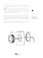
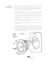
PN #319-0700
introduction
About your new loudspeakers
Thank you for purchasing the a/d/s/ 336PX loudspeaker system. The 336PX is without
question the finest automotive loudspeaker a/d/s/ has ever produced. It reflects most refined
technology combined with obsessive construction techniques to deliver unequalled
performance. The 336PX is assembled by specially trained craftspeople with years of
experience building a/d/s/ products. This elite group maintains extremely tight tolerance
control at each step, which assures that each 336PX precisely matches the performance curves
of the original reference.
The most obvious feature of the 336PX is the rugged and non resonant machined metal
woofer frame. This precision chassis is hand assembled from specially selected components to
assure that each frame has the precise geometric proportions for optimum performance. The
large open area and round support rods eliminate the reflections from the frame ribs which
can cause midrange coloration in ordinary loudspeakers. The frame’s bi-metallic construction
forms a resonance-canceling structure which guarantees the utmost sonic purity.
The woofer cone is a newly designed composite of a proprietary copolymer modified with a
filling made of an acid metasilicate of magnesium. This filling forms microscopic platelets
which help stiffen the cone while simultaneously providing a lossy mechanism to damp
undesired resonances.
The motor structure of the 336PX utilizes new geometry to create a symmetrical magnetic
field for low distortion. Also, to ensure high power handling, the center pole is vented along
with a series of perimeter vents to cool the voice coil.
The 336PX tweeter is based on a long line of a/d/s/ designs revered for their clarity and smooth
response. In the 336PX, the new conformal grille and solid aluminum mounting system help
to improve power response and dispersion.
And finally, the crossover used in the 336PX contains components which were each selected
for their own unique sonic signature. The capacitors are all high-quality polypropylene-film
types which have extremely low loss, and do not exhibit the harsh edgy sound of electrolytics
or the clarity-robbing softness of polyester types. For optimum ultra high frequency
performance, the series capacitors in the tweeter circuit are further bypassed with unique
thick-film Polypropylene capacitors specially made with stranded lead wires. This reduces the
loss caused by the main capacitors’ parasitic inductance, increasing clarity and improving
transient response. The crossover is mounted on an aluminum baseplate with a polished
acrylic cover, thereby keeping ferrous materials away from the circuitry as much as possible.
Installation and connection
The quality of the installation will affects the performance and reliability of all loudspeakers.
Installation
The high performance capability and construction methods used in the 336PX result in a more
demanding installation than conventional loudspeakers. Therefore we strongly recommend
that the 336PX be installed by an a/d/s/ authorized professional installer. A professional
installation can reduce the risk of damage to either your car or your audio components. If you
do choose to install the audio system yourself, we recommend that you carefully follow the
guidelines discussed in this booklet.
Installation tips and warnings
• Study the layout of your automobile thoroughly before you drill or cut any holes.
• Take extra care when working near gas tanks, gas lines, brake or hydraulic lines and
electrical wiring.
• Keep the woofers and the tweeters away from metal filings and shavings. Once foreign
objects are stuck to the magnets or tweeter dome, it will be virtually impossible to remove
them. Keep the tweeters in their protective bags until final mounting to prevent metal dust
or chips from passing through the grille and accumulating on the dome.
• Exercise caution when handling any of the 336PX drivers when the grilles are removed. A
slip of the hand with a screwdriver or other tool can result in irreparable damage to the cone
or dome.
• Do not install any of the components component where they will be subject to excessive
heat, moisture or dust; or where they will be kicked or repeatedly bumped or brushed.
• Make absolutely sure the woofer and tweeter are connected to the proper outputs of the
crossover network. If these connections are reversed, low-frequency signals will be fed to
the tweeter. If this happens, the tweeter will likely be damaged. Such damage is not covered
by the warranty.
• When removing or installing the grille of the 336PX speakers do not touch the woofer’s
rubber surround or the tweeter dome with the edge of the grille. Damage to the surround
or dome will significantly degrade performance.
• Never run wiring outside or beneath the vehicle where it can be damaged by road hazards
or the moving parts of the vehicle. Use existing wire channels, sill, panels, and molding strips
inside the automobile to hide the wiring for neat appearance and safety.
• Make sure your radio/cassette player and/or other equipment is turned off while connecting
the speaker terminals. Turn on the various components and slowly advance the volume
control only after checking and double checking all connections. NOTE: If sound is weak and
distorted, immediately turn down the volume and see the Troubleshooting section of this
manual.
1
Planning the installation
The modular configuration of the 336PX makes it possible to mount the individual units in a
variety of locations. However, due to the nature of the construction of the 336PX frames, high
precision is required when cutting the mounting holes for installation of the woofer. Likewise
the tweeter is designed for flush mounting only. You will need access to the area immediately
behind the tweeter mounting panel in order to tighten the locking ring.
speaker
placement
For the best imaging and most coherent sound, the output from the woofer and tweeter of
each channel should reach the listener at the same time and from the same direction. The best
results will generally be achieved when the woofer and tweeter are adjacent to each other.
Many installations however may dictate that the two units are separated. If they are mounted
too far apart, the sound they produce may lose coherence.
A woofer mounted on the front door, for example, could have its corresponding tweeter
mounted on the dashboard near the door. It would be inappropriate, however, to mount the
tweeter on the dashboard or front door with the woofer on the rear deck.
The 336PX bass / midrange speakers produce maximum undistorted bass output when
mounted on a rigid surface and in an enclosure which is acoustically isolated from the
passenger compartment. The front doors are often the best locations for the woofers. In some
cases you may be able to mount the woofers in the front kick panels if the areas behind the
panels are reasonably large. In other cases, it may be possible to use existing openings
provided by the auto manufacturer for factory options. Thin panels or shelves must be
reinforced with fiberboard or sheet metal. Steps should also be taken to eliminate air leaks in
and around the mounting surface.
Use the supplied templates when planning the installation. Be sure you have enough clearance
behind the mounting panel. When installing speakers on a rear deck, watch out for trunk lid
hinges and springs. If you are mounting speakers in doors, be sure they will not interfere with
the window operating mechanism. Check the intended installation location with the window
down as well as up.
Label the free ends of all wires before routing so they can be quickly and accurately identified.
It is especially important to avoid reversing the woofer and the tweeter connections.
Amplifier requirements
The 336PX will operate well on as little as 20Watts RMS per channel to achieve reasonable
volume levels in a moving vehicle without clipping the amplifier. We recommend a maximum
of 150 watts so as not to exceed the thermal or mechanical limitations of the speaker system.
The use of a low powered amplifier to try to attain very high output levels can lead to
overdriving the amplifier. This will generate high distortion levels which can easily damage the
loudspeakers, even if the amplifier’s rated power is far below the rated power of the
loudspeaker.
As a rule, do not turn the volume up past the point where you hear distortion from either an
overstressed speaker or amplifier. For the best performance and reliability, select an amplifier
2
with slightly more than you are likely to need to reproduce the desired volume levels. This
margin of reserve power will ensure that the amplifier will not attempt to deliver more than
it’s design allows.
Warning: Excessive sound pressure level can permanently damage your hearing. The
maximum volume levels attainable with a/d/s/ speakers, combined with high power
amplification, may exceed safe levels for extended listening. When listening at extreme
volume levels always use hearing protection, or turn it down!
The preparation of the mounting surface for the tweeter involves drilling a single 1-7/8” hole.
In most cases a circular hole-saw in a heavy-duty variable speed drill will be the best way to
cut this hole. Cut carpeting or fabric away from the hole locations to prevent tangling of fibers
in the drill bit. Only mount the 336PX tweeter into a location where you can gain access
behind the panel.
tweeter
installation
Once the hole is cut, pass the tweeter through the panel from the front and screw the knurled
locking ring onto the tweeter from the rear. Tighten the ring securely.
3
woofer
installation
Remove the trim panels and inspect the installation locations before you cut and drill the holes
required to mount the woofer. Removing the panel will also make it much easier to route
wiring inside the door. Look for original equipment speaker installation cutouts that can often
be used to install the woofers with little or no modifications. Use the template supplied to help
you locate and mark the holes needed to install the speakers.
When installing the 336PX woofer in a door be sure it will not interfere with the window
lowering mechanism. Be sure that the speaker wires clear all moving parts inside the door.
For each woofer you will need to cut one large hole and drill six small holes around the
circumference. If the mounting surface is covered by carpet or fabric, use a knife or razor to
cut the material away from the holes and cutting path. This prevents material or fibers from
becoming tangled in the drill bit or cutting blade.
We recommend that you use #8 or 4mm sheet metal or machine screws, depending on the
composition of the mounting surface. These are not included.
Clean the work areas of all filings and shavings with a vacuum cleaner before you proceed
with woofer mounting.
Route the speaker wire from the woofer installation locations to the crossovers. Pull the wire
through the installation hole and attach the wire to the terminals on the speakers. The speaker
terminals will accept up to #12AWG wire. Connect the positive wire to the positive (+)
terminal indicated by the red ring. See the information in the Polarity section of this manual
and the wiring diagrams. Push the wire back into the area behind the installation location. Be
sure it will not interfere with the speaker.
4
Set the woofer in the installation hole. If you are mounting the woofer to a hard surface, such
as wood or metal, install a rubber gasket around the periphery of the mounting hole. Align
the screw holes and drive in the six mounting screws. Gradually, tighten each in turn until the
speaker is well seated. Take care to not over-tighten the screws. When the woofer is properly
mounted install the metal grille in the speaker frame.
The crossover installation location should be reasonably accessible to allow easy connection of
the wires and easy adjustment of the controls. If the crossover must be mounted in an
inaccessible location make the speaker wire connections and the control adjustments before
crossover
installation
the final installation.
The current which flows through the inductors in the crossover creates a magnetic field
around each coil. If the two crossovers are mounted close to each other, the magnetic field
surrounding one crossover can be picked up by the other, affecting the sound quality of the
other channel. Also, ferrous metal adjacent to the crossover, such as the steel frame of the
vehicle, will negatively affect the operation of the inductors. While these effects occur with all
crossovers, the extreme transparency resolution of the 336PX system may allow these effects
to be heard more readily than with lesser loudspeakers. Therefore to deliver maximum
performance we recommend planning your installation so that the 336PX crossovers are
mounted as far apart from each other, and as far away from steel panels, as possible.
Mounting the 336PX crossover network requires four holes on a flat or nearly-flat surface. Set
the crossover in the installation location and use it as a template to mark the mounting screw
hole locations. Due to the size and weight of the crossover, #10 or 6mm hardware is
recommended.
As before, do not over-tighten the mounting screws; this is especially important if the
mounting surface is not perfectly flat.
Polarity
It is essential to maintain consistent phasing (polarity) for all amplifier-to-crossover and
crossover-to-speaker connections. The important thing is to be consistent in the way you make
every speaker, crossover and amplifier connection. Depending on the relative locations of the
woofer and tweeter to the listening position, the smoothest response may sometimes be
achieved with the tweeter polarity reversed. A switch is provided on the crossover for this. In
all cases, the left and right channels connections and adjustments should be identical.
5
making the
connection
There are two sets of input terminals on each 336PX crossover. One set is the high-frequency
input and output, with the other side the low-frequency input and output. Connect the wires
from the woofer to the low frequency output terminals and the tweeter wires to the high
frequency output terminals. The two sets of input terminals make it easy to bi-amplify or biwire the system. When the system is bi-amplified two amplifier channels are used to drive each
336PX. One pair of channels drives the tweeters, the other pair drives the woofers. If a single
amplifier channel is used for each speaker system, the 336PX should be bi-wired by attaching
a separate speaker wire to the high frequency and low frequency inputs of the crossover and
connecting the wires in parallel at the amplifier as shown in fig.3. Please note that the
amplifier load with this connection is 4-Ohms.
bi-wiring
6
fig.3.
There are two ways bi-amplification is typically accomplished. One is when both pairs of
amplifier channels receive full range signals. The advanced a/d/s/ multi-channel amplifiers have
facilities to tie the inputs together, making it easy to deliver signals simultaneously to multiple
channels. With other amplifiers a set of “Y” cords may have to be used.
The other, more common way to bi-amplify the 336PX is to use electronic crossovers. The
crossovers are inserted between the signal source and the amplifiers. The advanced a/d/s/
multi-channel amplifiers have built in crossovers which may be used also. While this is
normally the preferred method of bi-amplifying most systems, the quality and precision of the
336PX crossover favors the use of it’s supplied crossover, not an external active one. Because
of the complex and precise crossover contours required by the 336PX, it is unlikely that an
electronic crossover will provide superior results.
fig.4.
bi-amplified
7
adjustments
When you have finished the physical installation and electrical connections, test the system.
Turn on your radio/tape or CD player, but leave the volume control very low. Tune in a station
or play a CD or tape, and check the individual drive units to make sure they are all operating.
If you hear poor sound, distortion, or no sound, immediately turn off the system and see
Troubleshooting. Operate the balance and fader controls to make sure all connections have
been properly made. When you are satisfied with the basic installation, proceed with the final
adjustments.
Tweeter level
Differing installations require different amounts of high frequency output. If the 336PX
tweeters are mounted relatively close to the listener, you may want to reduce their output. If
they are mounted farther away from the listener, or if the interior of the car is very absorptive,
you may want increased high-frequency output. The 336PX crossovers have a switch that lets
you adjust the high frequency output.
Listen carefully to some wide range, high-quality program material, paying particular attention
to the bass/treble balance. If your system is Bi-wired, turn the system down and move the
switches from the “mid” position to the “high” or “low” position. Listen to the same
selection and decide if the treble/bass balance of the system is more natural or not. Repeat
the process until the most natural bass/treble balance is achieved. If your system is bi-amped,
leave the tweeter level control in the “mid” position and use the input sensitivity controls on
the amplifier channels driving the tweeters to fine tune their level.
Tweeter polarity
The varying position of the listener with regard to the individual loudspeaker drivers also has
an effect on the response of the 336PX system in the crossover frequency region. Typically the
crossover equalization switch should be left in the “A” position. This produces the smoothest,
most natural response when the tweeter and woofer are at an equal distance from the
listener. In some installations, the spacing of the woofer and tweeter relative to the listening
position may result in a response dip at the crossover when the in-phase “A” position is used.
If this happens, set the Tweeter Polarity switch on both crossovers to the “B” position. If you
have access to a signal generator or a CD with test tones, try both switch positions while
playing a tone at or near 3kHz. Leave the switch in the position which gives the most output.
tweeter protection
The 336PX tweeter is protected by a solid-state protection device.
In the event of
overpowering or excessive amplifier clipping, this protection circuit will reduce the tweeter
level for the duration of the overload. Once the condition causing the overload is rectified the
tweeter operation will be restored. When the protection circuit is activated, an LED located
adjacent to the tweeter polarity switch will flicker in the presence of a high-level audio signal.
This should happen rarely if at all. If the tweeter protection trips often it is a sign of either an
amplifier which is under or over powered, or a problem with the tweeter or itís wiring. Please
contact your a/d/s/ dealer or a/d/s/ Customer Service department if this should occur.
8
The following is a brief guide to some typical problems, their probable causes, and
recommended remedies. Should you encounter difficulties beyond the scope of this
troubleshooting guide, consult your a/d/s/ dealer or your car stereo installer. Do not attempt
your own repairs. Any repairs to the system must be made by a/d/s/ or an authorized a/d/s/
troubleshooting
service facility.
No sound, low or distorted sound
Check all 12-volt power connections to your radio/tape or CD player and power amplifier.
Check all power fuses related to the sound system. Check all audio connections between the
head unit and amplifier, between the amplifier and the crossover, and between the crossovers
and the speakers. If only one channel is out, try interchanging cables between channels to try
to isolate the problem. If the sound is distorted or faint, the problem may be a bad connection
or faulty ground. With the volume turned down, wiggle all wire connections to try to find an
intermittent connection. Replace any faulty wiring and reconnect loose wires.
If none of these steps solves the problem, one or more of your car stereo components may be
defective. Have the system checked by qualified personnel.
Poor tonal balance
If the sound on the initial test is thin and weak, immediately turn down the volume and check
the woofer and tweeter connections to the crossovers to be sure they are correct. Be sure the
tweeter level control switch is properly set.
Make sure you are getting a high-quality signal from your signal source. Check all the tone
controls, equalizer settings, tape or CD selector, and noise reduction settings. Tape players
sometimes require cleaning or adjustments to produce proper high-frequency response. If you
suspect your tape or CD player, have a car stereo installer test the unit.
Poor tonal balance may result if one or more of the drive units is not operating. While playing
a high-quality music program at a moderate level, put your ear close to each drive unit in turn
and listen for output.
Finally, if you suspect a damaged component, contact your a/d/s/ dealer or installer.
If you want to consult the factory, write or call our customer service department:
Customer Service Department
analog and digital systems, inc.
300 Wildwood Avenue
Woburn, MA 01801
phone: 781.729.1140
fax: 781.729.3535
9
specifications
frequency response
sensitivity
40Hz to 22kHz, ±3dB
91.5dB with 2.83 volt RMS pink noise measured at 1
meter
impedance
recommended power
tweeter
4 Ohms, nominal
20 to 150 watts RMS
1" / 25mm diameter driver with a copolymer dome, a
single layer, oxygen-free copper voice coil wound on a
high-temperature Kapton form, and a precision- ground
neodymium magnet structure.
woofer
6-1/2" / 165mm driver with a curvilinear profile cone
made from an injection-molded copolymer filled with an
acid metasilicate of magnesium. The woofer features a
butyl-rubber surround and a 1” oxygen-free copper wire
voice coil wound on a high temperature Kapton form.
crossover
Passive hybrid LCR network with precision, low DC
resistance, high current air-core coils and low-loss, close
tolerance, high Q, polypropylene capacitors. Three
position tweeter level switch and tweeter polarity
switch.
10
manufacturer‘s name:
manufacturer‘s address:
analog and digital systems, inc.
one progress way
wilmington, ma 01887
usa
declaration of
conformity
declares, that the product
product name:
conforms to the following standards:
336PX
EN 50 081-1/1992
EN 50 082-1/3.1995
european contact:
Olberto Pinto
RCF Artesuono SRL
Maurizo, Italy
11
warranty
information
There are two things you must do to ensure trouble free service in the event you need warranty repairs.
1 - Keep your original sales receipt in a safe place. A copy of the receipt will be required to obtain
warranty service.
2 - Be sure your retail dealer has written the date, the model number, and the serial number of the
Product on the receipt.
To give yourself an extra measure of protection, make a separate record of the information about your
purchase and keep it in a safe place. In the event you misplace the sales receipt, your dealer may be
able to give you a copy.
Take a moment now to read the terms of your warranty. Check to be sure your sales receipt is dated
and has the Product model number on it. Then put it away in a safe place.
When shipping a Product in for service:
• Enclose a copy of your original sales receipt that has the date, the Product model number and serial
number (if applicable) written on it.
• Always ship Products in the complete original packing material.
• Avoid shipping Products via the Postal service. If you must use the Postal service, be sure to register
and insure the package.
a/d/s/ Limited Warranty
Analog and Digital Systems, Inc. (a/d/s/) warrants to the original consumer purchaser of the a/d/s/
Products described in this manual, that the Product will be free from defects in materials and
workmanship for a period of one (1) year after the date of purchase. If the Product is installed by an
authorized a/d/s/ retail dealer, the warranty is extended to (3) three years, a/d/s/’ sole obligation under
this warranty shall be to provide, without charge, parts and labor necessary to remedy the defects, if
any, that appear during the warranty period.
This warranty is the sole and exclusive express warranty given with respect to the Product. All other
express warranties are hereby excluded. Neither a/d/s/ nor the authorized dealer who sells the Product is
responsible for indirect, incidental, or consequential damages. Some states do not allow the exclusion
or limitation of incidental or consequential damages, so the above limitation or exclusion may not apply
to you. This warranty gives you specific legal rights and you may also have other rights which vary from
state to state.
IMPORTANT - Keep your original sales receipt. Be sure the retail dealer has written on it the date, model
number, and serial number (if applicable) of the Product. This information is required for warranty
service.
This warranty is limited to:
• Products purchased from authorized a/d/s/ retail dealers in the United States. a/d/s/ will supply a list of
authorized dealers on request. In order to obtain warranty service you must:
• Return the Product, freight prepaid, to the a/d/s/ dealer from which it was purchased, an authorized
a/d/s/ independent service agency, or to a/d/s/. If necessary you may call a/d/s/ Customer Service for
the names and addresses of authorized independent service agencies in your area.
• Provide proof of purchase in the form of a copy of your original sales receipt. The date, model
number, and serial number (if applicable) of the Product must be written on the sales receipt.
This warranty does not cover:
• Damage that is a result of misuse, abuse, accident (including but not limited to damage by water),
faulty hookup, defective or maladjusted associated equipment, or the use of the Product with
equipment for which it was not intended.
• Cosmetic defects that appear more than thirty (30) days after the date of purchase. Cosmetic damage
caused by improper handling is also excluded.
• Products that are used for commercial purposes.
• The cost of removing or reinstalling the Product.
• Damage that occurs while the Product is being shipped to whoever will service it. See the information
above regarding shipping procedures.
This warranty is void if:
• The product identification or serial number label is removed or defaced in any way.
• The Product is serviced or repaired by any one other than a/d/s/ or an authorized a/d/s/ dealer or
service agency.
analog and digital systems,inc
300 wildwood ave.
woburn, massachusetts 01801 USA
p 781.729.1140
f 781.729.3535
17