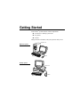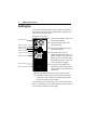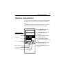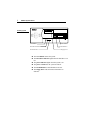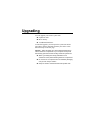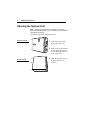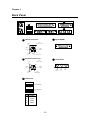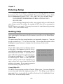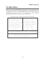
1
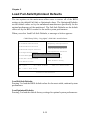
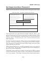
PC0027 mech 4/12/2000 4:55 PM Page 3 Apollo/Shadowhawk Apollo/Shadowhawk 440S Series User’s Manual u s e r m a n u a l System Manual ii PREMIO System Manual Copyright PREMIO is a registered trademark of Premio Computer, Inc. All other brands and product names are trademarks or registered trademarks of their respective companies. © 1997 by Premio Computer, Inc. All rights reserved. Printed in Taiwan. Version 2.0, September, 1997. Disclaimers PREMIO makes no representation or warranties, either expressed or implied, with respect to the contents of this publication and specifically disclaims the implied warranties of merchantability or fitness for a particular purpose. PREMIO shall not be liable for technical or editorial errors or omissions in this publication, or for incidental or consequential damages resulting from the furnishing, performance, or use of this publication. We reserve the right to revise this publication and to make changes from time to time in its contents without notification. iii Contents GETTING STARTED ..................................................................1 Setting Up ........................................................................2 Switches and Indicators.................................................3 UPGRADING ..............................................................................5 Opening the System Unit ...............................................6 Installing an Expansion Card ........................................7 Installing Memory ...........................................................8 Installing a SIMM .................................................................8 Removing a SIMM................................................................9 Installing a DIMM ................................................................9 Removing a DIMM .............................................................10 Installing a Hard Drive..................................................11 GETTING HELP........................................................................12 Troubleshooting ...........................................................12 Monitor Does Not Work .....................................................12 Keyboard Does Not Work...................................................13 Mouse Does Not Work........................................................13 System Unit Problems.........................................................14 Hard Disk Problems ............................................................14 iv PREMIO System Manual Warranty Service.......................................................... 15 Technical Support........................................................ 15 PREMIO on the Internet............................................... 15 APPENDIX ................................................................................16 Limited 3-Year Warranty.............................................. 16 FCC Standards ............................................................. 18 Important Safety Instructions ..................................... 19 Getting Started Your PREMIO® system consists of three components: a mid-tower or desktop system unit a keyboard a mouse Add your choice of monitor, and your system is ready to use. System Unit Mid-tower system Keyboard Mouse Desktop system System Unit Keyboard Mouse 2 PREMIO System Manual Setting Up To set up your PREMIO system, simply connect your monitor, the mouse, the keyboard, and any additional components you want to use to the system unit. Follow these easy steps: 1 Attach your monitor’s video cable Power Connector to the video connector. 2 Attach the mouse cable to the Mouse Connector Keyboard Connector USB Connector Serial-1 Connector Serial-2 Connector Parallel Connector Video Connector Sound Card Connectors mouse connector. 3 Attach the keyboard cable to the keyboard connector. 4 Attach the cables for any additional components, such as a printer, scanner, or modem, to the parallel, serial, or universal serial bus (USB) connector, as directed in the component’s manual. 5 If your system is equipped for multimedia, attach your speakers and microphone to the sound card connectors. 6 Plug your monitor’s power cord into a power outlet. 7 Attach the female end of the system power cord to the system unit’s power connector, and then plug the other end of the cord into a power outlet. Your PREMIO system is now ready to use. To start the system, turn on your monitor’s power switch and then press the system power switch as shown on the next page. Switches and Indicators 3 Switches and Indicators The system unit’s front panel provides access to the CD-ROM and floppy drives, and to the system’s switches and indicator lights. The illustration below shows a mid-tower system. If you have a desktop system, turn to the illustration on the next page. The CD-ROM drive reads information on CDs. Mid-tower system CD ROM Drive Floppy Drive Power Switch The floppy drive reads and writes information on diskettes. The power switch turns the system on and off. The hard drive indicator lights when the hard drive is in use. The power indicator lights when the system is on. Hard Drive Indicator Power Indicator Reset Button The reset button restarts the system. 4 PREMIO System Manual Desktop system Reset Button Hard Drive Indicator Power Indicator Power Switch CD ROM Drive Floppy Drive The reset button restarts the system. The hard drive indicator lights when the hard drive is in use. The power indicator lights when the system is on. The power switch turns the system on and off. The CD-ROM drive reads information on CDs. The floppy drive reads and writes information on diskettes. Upgrading You can upgrade your PREMIO system with: Expansion cards More memory An additional hard drive To install an upgrade, you must open the system unit. Before proceeding, read the important cautionary note below. Then follow the steps on the next page. Caution! Static discharge can cause permanent damage to internal electronic components of your computer. Always use the following precautions when working inside the system unit: Wear a grounding wrist strap (available at most electronics stores) when handling electronic components. Do not remove a component from its antistatic packaging until you are ready to install it. Keep one hand in contact with the metal system case. 6 PREMIO System Manual Opening the System Unit Note Opening the system unit could affect your warranty. Check with the dealer where you purchased your system before opening the system unit. To open the system unit, follow these steps Mid-tower system 1 Turn off the system and unplug the power cord. 2 Remove the screws securing the side panel (mid-tower) or case (desktop) at the rear of the system unit. Desktop system 3 Slide the side panel or case up and to the rear, and remove it. Installing an Expansion Card 7 Installing an Expansion Card To install an expansion card, open the system unit as described on the previous page. Then follow these steps: 1 Remove the screw securing the slot bracket cover for the expansion slot you want to use. Save the screw to secure the expansion card. 2 Insert the expansion card firmly into the slot, making sure it is seated completely. 3 Secure the card with the saved screw. 8 PREMIO System Manual Installing Memory Note For details on memory configuration, including the placement and type of memory to use in your system, refer to the motherboard user’s manual that came with your system. Follow these general guidelines when adding memory: Use only the same type of memory throughout. For example, do not mix EDO and fast page memory. SIMMs must be installed in pairs, and both SIMMs in the pair must be the same size and speed. For example, do not install one 16-MB and one 8-MB SIMM. Installing a SIMM To install a SIMM, follow these steps: 1 Insert the SIMM into the socket at a 45° angle. (SIMMs can be installed only one way.) 2 Gently press the SIMM up into a vertical position until it snaps into place. The SIMM’s clips will hold it firmly at a 90° angle when it is properly installed. Installing Memory 9 Removing a SIMM To remove a SIMM, follow these steps: 1 Press the holding clips on both sides of the SIMM outward to release it. 2 Tilt the SIMM to a 45° angle. 3 Pull the SIMM up and out of the socket. Installing a DIMM To install a DIMM, follow these steps: 1 Insert the DIMM vertically into the socket. (DIMMs can fit into the slot only one way.) 2 Push down on the DIMM to seat it, and then raise the plastic clips at either side to lock it in place. 10 PREMIO System Manual Removing a DIMM To remove a DIMM, follow these steps: 1 Push down and out on the plastic clips at either end to release them. 2 Pull the DIMM up and out of the socket. Installing a Hard Drive 11 Installing a Hard Drive To install a hard drive in your system, follow these steps: Mid-tower system Desktop system 1 Disconnect the hard drive cable and power connector. 2 Remove the two screws securing the drive bay. 3 Slide the bay toward the rear of the system unit to remove it. 4 Insert the new drive into an open position in the bay and secure it with four screws. 5 Slide the bay back into the system unit and secure it with two screws. 6 Connect the cables. Getting Help Troubleshooting Your PREMIO system is designed to provide years of troublefree performance. If you have a problem with your system, first check the information in this section for a quick solution. Monitor Does Not Work If your monitor appears not to be working properly: Check that the monitor’s power cable is securely attached to the monitor and to an outlet that is receiving power. Check that the monitor’s video cable is securely attached to the monitor and to the system unit’s video card connector. Check that the monitor’s power switch is on. Adjust the monitor’s brightness and contrast controls. If possible, substitute another monitor that is in good working order. If the substitute works, your monitor may need repair or replacement. Troubleshooting 13 Keyboard Does Not Work If the NumLock indicator in the upper right corner of the keyboard does not light when the system powers up, or the keyboard does not work: Check that the keyboard cable is securely attached to the system unit’s keyboard connector. If possible, substitute another keyboard that is in good working order. If the substitute works, your keyboard may need replacement. Mouse Does Not Work If your mouse pointer does not move or moves erratically when you move the mouse: Check that the mouse cable is securely attached to the mouse connector on the system unit. Disassemble the mouse and clean the roller ball. 14 PREMIO System Manual System Unit Problems The fan inside the system unit should make a low, steady sound when operating properly. If the fan is totally silent: Check that the system power cord is securely attached to the back of the system unit and to a power outlet. Verify that the outlet has power. If possible, substitute another power cord that is in good working order. If the substitute works, replace your power cord. If the fan makes excessive noise: Turn off the system, open the system unit case, and inspect the fan for any obstructions. Turn on the system and listen closely to the fan. If the noise comes from inside the fan housing, your power supply may need replacement. Hard Disk Problems Your hard disk should make a slight whirring sound when operating properly. If the disk is totally silent: Turn off the system, open the system unit case, and check that the power cable between the power supply and the hard disk is securely attached at both ends. If it is, your hard disk may be defective. If the hard disk makes excessive noise: Turn off the system, open the system unit case, and remove the hard disk power cable connector from the hard disk. Then turn the system back on. If the noise disappears, your hard disk may be defective. If you have more than one hard disk, repeat the same procedure for each disk. Warranty Service 15 Warranty Service If you have a problem with your PREMIO system that requires service during the warranty period, contact the dealer where you purchased your system. Your dealer will try to resolve the problem for you. If your dealer cannot resolve the problem, you can contact PREMIO directly at the address below. Note To obtain warranty service, you must provide proof of purchase, including the purchase date. Technical Support You can contact PREMIO technical support at the following address: Premio Computer, Inc. 918 Radecki Court City of Industry, CA 91748 Telephone: 800-568-6388 Fax: 626-839-3191 Email: [email protected] PREMIO on the Internet PREMIO maintains a web page on the Internet with the latest information on PREMIO products, updated drivers, answers to common problems, a Windows 95 troubleshooting guide, and more. Visit our web page at: http://www.premiopc.com Appendix Limited 3-Year Warranty Premio Computer, Inc. warrants its line of PREMIO® computer systems (hereinafter “Product”) to be free from defects in material and workmanship for a period of three (3) years from the date of original purchase from Premio Computer, Inc. or a Premio Computer, Inc. authorized reseller. This warranty does not cover monitor and LCD panels, nor third-party hardware and software which has a separate manufacturer’s warranty. Warranty for such third-party hardware and software, if any, is subject to the third-party’s warranty policy. PREMIO branded monitors are warranted as follows: Three (3) year parts and labor except for CRT One (1) year parts and labor for CRT PREMIO branded LCD panels are warranted as follows: One (1) year parts and labor SERVICE UNDER WARRANTY If this Product fails to be in good working order during this 3year warranty period (or specific period of time as noted above), Premio Computer, Inc. will, at its option, repair or replace the Product. Repair parts and/or replacement Products may be either new or reconditioned at Premio Computer Inc.’s discretion. The limited warranty does not include service to repair damage from improper installation, abuse or modifications to the Product not approved in writing by Premio Computer, Inc. Any service repair outside the scope of this limited warranty shall be at Premio Computer, Inc.’s or its Authorized Service Provider’s rates and terms in effect. This warranty is valid only within the United States and applies only to Products which are new and in cartons which are unopened on the date of purchase. Limited 3-Year Warranty 17 EXCLUSIONS FROM PREMIO, INC. LIMITED WARRANTY PROGRAM ALL OTHER EXPRESSED AND IMPLIED WARRANTIES FOR THIS PRODUCT, INCLUDING THE WARRANTIES OF MERCHANTABILITY AND FITNESS FOR A PARTICULAR PURPOSE, ARE HEREBY DISCLAIMED. IF THIS PRODUCT IS NOT IN GOOD WORKING ORDER AS WARRANTED ABOVE, PREMIO COMPUTER, INC.'S SOLE AND EXCLUSIVE REMEDY SHALL BE REPAIR OR REPLACEMENT AS STATED ABOVE. IN NO EVENT WILL PREMIO COMPUTER, INC. BE LIABLE TO THE CUSTOMER OR ANY THIRD PARTY FOR ANY DAMEAGES IN EXCESS OF THE PURCHASE PRICE OF THE PRODUCT. THIS LIMITATION APPLIES TO DAMAGES OF ANY KIND INCLUDING ANY DIRECT OR INDIRECT DAMAGES, LOST PROFITS, LOST SAVINGS OR OTHER SPECIAL, INCIDENTAL, EXEMPLARY OR CONSEQUENTIAL DAMAGES WETHER ARISING OUT OF THE USE OF OR INABILITY TO USE SUCH PRODUCT, EVEN IF PREMIO COMPUTER, INC. OR AN AUTHORIZED PREMIO COMPUTER, INC. REPRESENTATIVE OR DEALER HAS BEEN ADVISED OF THE POSSIBILITY OF SUCH DAMAGES OR OF ANY CLAIM BY ANY OTHER PARTY. SOME STATES DO NOT ALLOW THE EXCLUSION OR LIMITATION OF INCIDENTAL OR CONSEQUENTIAL DAMAGES FOR SOME PRODUCTS, SO THE ABOVE LIMITATIONS OR EXCLUSIONS MAY NOT APPLY TO YOU. PREMIO COMPUTER, INC. AUTHORIZED RESELLERS AND SERVICE PROVIDERS/PARTNERS MAY BE CHANGED, ADDED OR DELETED, WITHOUT NOTICE OR LIABILITY. PREMIO COMPUTER, INC. DISCLAIMS ANY AUTHORIZED RESELLERS AND SERVICE PROVIDER/PARTNER TO THE PROGRAM. THIS WARRANTY GIVES YOU SPECIFIC LEGAL RIGHTS AND YOU MAY ALSO HAVE OTHER RIGHTS WHICH MAY VARY FROM STATE TO STATE. FCC Standards The FCC (Federal Communications Commission) restricts the amount of radiation and radio frequency emissions from computing equipment. This equipment generates and uses radio frequency energy and if not installed and used properly in strict accordance with the operation instructions, reference manuals, and the service manual, may cause interference to radio or television reception. This equipment can be tested and found to comply with the limits for a Class B digital device pursuant to part 15 of the FCC rules. There limits are designed to provide reasonable protection against harmful interference in a residential installation. This equipment generates, uses, and can radiate radio frequency energy and, if not installed and used in accordance with the instructions, may cause harmful interference to radio communications. However, there is no guarantee that interference will not occur in a particular installation. If this equipment does cause harmful interference to radio or television reception, which can be determined by turning the equipment off and on, then the user is encouraged to try to correct the interference by one or more of the following procedures: Reorient or relocate the receiving antenna. Increase the separation between the equipment and receiver. Connect the equipment into an outlet on a circuit different from that to which the receiver is connected. Consult the dealer or an experienced radio/TV technician for help. Important Safety Instructions 19 Important Safety Instructions These instructions are provided by Underwriters Laboratories, Inc. 1. Read all of these instructions and save them for later reference. 2. Follow all warnings and instructions marked on the product. 3. Unplug this product from the wall outlet before cleaning. Do not use liquid or aerosol cleaners. Use a damp cloth for cleaning. 4. Do not use this product near water. 5. Do not place this product on an unstable cart, stand or table. The product may fall, causing serious damage to the product. 6. Slots and openings on the cabinet and the back or bottom are provided for ventilation. To ensure reliable operation of the product and to protect it from overheating, do not block or cover these openings. The openings should never be blocked by placing the product on a bed, sofa, rug or other similar surface. This product should never be placed near or over a radiator or heat register. This product should not be placed in a built-in installation unless proper ventilation is provided. 7. This product should be operated from the type of power source indicated on the marking label. If you are not sure of the type of power available, consult your dealer or local power company. 8. This product is equipped with a 3-wire grounding-type plug, a plug having a third (grounding) pin. This plug will only fit into a grounding-type power outlet. This is a safety feature. If you are unable to insert the plug into the outlet, contact your electrician to replace your obsolete outlet. Do not defeat the safety purpose of the grounding-type plug. 9. Do not allow anything to rest on the power cord. Do not locate this product where the cord will be walked on. 10. If an extension cord is used with this product, make sure that the total of the ampere ratings on the products plugged into the extension cord do not exceed the extension cord ampere rating. Also, make sure that the total of all products plugged into the wall outlet does not exceed 15 amperes. 11. Never push objects of any kind into this product through cabinet slots as they may touch dangerous voltage points or short out parts that could result in a risk of fire or electric shock. Never spill liquid of any kind on the product. 12. Except as explained elsewhere in this manual, don't attempt to service this product yourself. Opening and removing those covers that are marked “Do Not Remove” may expose you to dangerous voltage points or other risks. Refer all servicing on those compartments to service personnel. 13. Unplug this product from the wall outlet and refer servicing to qualified service personnel under the following conditions: A. B. C. D. E. F. When the power cord or plug is damaged or frayed. If liquid has been spilled into the product. If the product has been exposed to rain or water. If the product does not operate normally when the operating instructions are followed. Adjust only those controls that are covered by the operating instructions since improper adjustment of other controls may result in damage and will often require extensive work by a qualified technician to restore the product to normal operation. If the product has been dropped or the cabinet has been damaged. If the product exhibits a distinct change in performance, indicating a need for service. CONTENTS Chapter 1. Introduction ............................................................... 1-1 Mainboard Specifications .......................................................... 1-2 Mainboard Layout ..................................................................... 1-4 Jumpers & Connectors .............................................................. 1-5 Back Panel ............................................................................... 1-6 Chapter 2. AWARD® BIOS Setup ................................................. 2-1 Entering Setup .......................................................................... 2-2 Getting Help .............................................................................. 2-2 The Main Menu ......................................................................... 2-3 Standard CMOS Features ......................................................... 2-4 Advanced BIOS Features .......................................................... 2-5 Advanced Chipset Features ...................................................... 2-6 Integrated Peripherals ............................................................... 2-7 Power Management Setup ........................................................ 2-8 PNP/PCI Configurations ............................................................ 2-9 PC Health Status .................................................................... 2-10 Frequency/Voltage Control ...................................................... 2-11 Load Fail-Safe/Optimized Defaults .......................................... 2-12 Set Supervisor/User Password ................................................ 2-13 L Introduction Chapter 1. Introduction The MS-6337 LE5 ATX mainboard is a high-performance computer mainboard based on Intel® 815EP chipset. The MS-6337 UMB (Universal Motherboard) is optimized to support the whole series of new generation Intel® Pentium® III (FC-PGA/FC-PGA2) processors for high-end business/personal desktop markets. The Intel 815EP chipset contains two components: the 82815EP Memory Controller Hub (MCH) and the 82801BA I/O Controller Hub 2 (ICH2). The MCH integrates a 66/100/133-MHz, P6 family system bus controller , AGP (2X/ 4X) discrete graphics card, 100/133-MHz SDRAM controller, and a high speed accelerated hub architecture interface for communication with the ICH2. The ICH2 integrates an UltraATA/100 controller, 2 USB host controllers with a total of 4 ports, LPC interface controller, FWH interface controller, PCI interface controller, AC97 digital link, integrated LAN controller, and a hub interface for communication with the MCH. This chapter contains the following topics: Mainboard Specifications Mainboard Layout Jumpers & Connectors Back Panel 1-1 1-2 1-4 1-5 1-6 Chapter 1 Mainboard Specifications CPU ! Support Socket370 for the whole series of new generation Intel® Pentium® III(FC-PGA/FC-PGA2) processors. ! Support 500MHz, 550MHz, 600MHz, 633MHz, 667MHz, 700MHz, 733MHz, 800MHz, 866MHz, 933MHz, 1GHz, 1.1GHz, 1.13GHz and up to 1.2GHz. Chipset ! Intel® 815EP chipset - 544 BGA - AGP 4x/2x universal slot - Support 66/100/133MHz FSB ! Intel® ICH2 chipset. - AC97 Audio support - 2 full IDE channels, up to ATA100 - Low pin count interface for SIO - USB controller 1.1 Main Memory ! Support three 168-pin DIMM sockets. ! Support a maximum memory size of 512MB SDRAM. Slots ! One CNR (Communication Network Riser). ! One AGP (Accelerated Graphics Port) 2x/4x slot ! Six PCI 2.2 32-bit Master PCI Bus slots. All PCI slots can be used as master. ! Support 3.3v/5v PCI bus Interface. On-Board IDE ! An IDE controller on the ICH2 chipset provides IDE HDD/CD-ROM with PIO, Bus Master and Ultra DMA 66/100 operation modes. ! Can connect up to two IDE devices. On-Board Peripherals ! On-Board Peripherals include: - 1 floppy port supports 2 FDD with 360K, 720K, 1.2M, 1.44M and 2.88Mbytes. - 2 serial ports (COMA/COMB) 1-2 Introduction - 1 parallel port supports SPP/EPP/ECP mode - 2 USB ports Audio ! ICH2 chip integrated ! Support 2 channel audio BIOS ! The mainboard BIOS provides Plug & Play BIOS which detects the peripheral devices and expansion cards of the board automatically. ! The mainboard provides a Desktop Management Interface (DMI) function which records your mainboard specifications. Dimension ! ATX Form Factor Mounting ! 6 mounting holes. 1-3 Chapter 1 Top : mouse Bottom: keyboard Bottom: COM A COM B FDD DIMM 3 Top : Parallel Port DIMM 2 DIMM 1 SOCKET 370 ATX Power Supply USB Top : port 1 Bottom: port 2 SW1 CPUFAN Mainboard Layout Intel 815EP chipset Top : Game port IDE 1 MODEM_IN CD_IN AUX_IN J2 Bottom: Line-Out Line-In Mic AGP Slot PCI Slot 1 PCI Slot 3 MS-6337LE5ATXMainboard 1-4 JBAT2 CNR J7 JFP1 PCI Slot 6 JWOL1 FWH PCI Slot 5 JMDM1 SYSFAN BATT + ICH 2 PCI Slot 2 Introduction Jumpers & Connectors SW1 $ Overclocking is operating a CPU/Processor beyond its specified frequency. SW1 jumper is used for overclocking. ! # " J7 Buzzer/ Chassis Intrusion Green Speaker Reserved Switch # IR J7 is a Front Panel Connector. Speaker Output Short 6-8 pin to activate AC97_SPKR Short 8-10 pin to activate onboard Buzzer. Reserved IRTX IRRX JFP1 Buzzer (short pin) 14 15 The case connector block JFP1 allows you to connect to the Power Switch, Reset Swtich, Speaker, Power LED, and HDD LED on the case. + + Keylock Speaker Reset Switch HDD Dual LED Power Color LED Power LED Switch Single Color LED LED5 JWOL1 LED 5 indicates the DIMM power. When LED 5 is powered on, do not attempt to insert or remove the DIMM module. 3 MP_WAKEUP GND 5VSB JMDM1 1 5 5VSB NC MDM_WAKEUP GND This connector allows you to connect to a modem card with Wake On Ring function. The connector will power up the system when a signal is received through the modem card. 1 NC J2 JBAT2 This connector allows you to connect to a LAN card with Wake On LAN function. You can wake up the computer via remote control through a local area network. J2 is used to check the AGP chipset temperature on AGP card. This function is reserved upon request. 3 3 2 2 1 Clear CMOS 1 A battery must be used to retain the mainboard configuration in CMOS RAM. Short 1-2 pins of JBAT2 to store the CMOS data. Keep CMOS 1-5 Chapter 1 Back Panel 1 4 LPT 1 3 2 COM B COM A 1 Pin5 Mouse Clock Pin6 NC Pin4 VCC 2 Pin3 GND Pin1 Mouse DATA Keyboard Connector Pin4 VCC Pin2 NC 5 Pin5 KBD Clock Pin6 NC 3 4 Joystick/MIDI Mouse Connector Pin2 NC 5 Audio Ports Pin3 GND Line Out Pin1 KBD DATA USB Ports USB Port 1 1 2 3 4 USB Port 2 PIN SIGNAL 1 VCC 2 -Data 3 +Data 4 GND 1-6 Line In MIC AWARD® BIOS Setup Chapter 2. AWARD® BIOS Setup AWARD® BIOS Setup The mainboard uses AWARD® BIOS ROM that provides a setup utility for users to modify the basic system configuration. The information is stored in a battery-backed CMOS RAM so it retains the Setup information when the power is turned off. This chapter provides you with the overview of the BIOS Setup program. It contains the following topics: Entering Setup Getting Help The Main Menu Standard CMOS Features Advanced BIOS Features Advanced Chipset Features Integrated Peripherals Power Management Setup PNP/PCI Configurations PC Health Status Frequency/Voltage Control Load Fail-Safe/Optimized Defaults Set Supervisor/User Password 2-1 2-2 2-2 2-3 2-4 2-5 2-6 2-7 2-8 2-9 2-10 2-11 2-12 2-13 Chapter 2 Entering Setup Power on the computer. When the below message appears briefly at the bottom of the screen during the POST (Power On Self Test), press <Del> key or simultaneously press <Ctrl>, <Alt>, and <Esc> keys to enter Setup. TO ENTER SETUP BEFORE BOOT, PRESS <CTRL-ALT-ESC> OR <DEL> KEY If the message disappears before you respond and you still wish to enter Setup, restart the system by turning it OFF then On or pressing the RESET button to try again. You may also restart by simultaneously pressing <Ctrl>, <Alt>, and <Delete> keys. Getting Help After entering the Setup menu, the first menu you will see is the Main Menu. Main Menu The main menu lists the setup functions you can make changes to. You can use the control keys ( ↑↓ ) to select the item. The on-line description of the highlighted setup function is displayed at the bottom of the screen. Sub-Menu If you find a right pointer symbol (as shown in the right view) appears to the left of certain fields that means a sub-menu can be launched from this field. A sub-menu contains additional options for a field parameter. You can use control keys ( ↑↓ ) to highlight the field and press <Enter> to call up the submenu. Then you can use the control keys to enter values and move from field to field within a sub-menu. If you want to return to the main menu, just press the <Esc >. !IDE !IDE !IDE !IDE Primary Master Primary Slave Secondary Master Secondary Slave General Help <F1> The BIOS setup program provides a General Help screen. You can call up this screen from any menu by simply pressing <F1>. The Help screen lists the appropriate keys to use and the possible selections for the highlighted item. Press <Esc> to exit the Help screen. 2-2 AWARD® BIOS Setup The Main Menu Once you enter Award® BIOS CMOS Setup Utility, the Main Menu (Figure 1) will appear on the screen. The Main Menu allows you to select from twelve setup functions and two exit choices. Use arrow keys to select among the items and press <Enter> to accept or enter the sub-menu. CMOS Setup Utility - Copyright(C) 1984-2001 Award Software Standard CMOS Features Frequency/Voltage Control Advanced BIOS Features Load Fail-Safe Defaults Advanced Chipset Features Load Optimized Defaults Integrated Peripherals Set Supervisor Password Power Management Setup Set User Password PnP/PCI Configurations Save & Exit Setup PC Health Status Exit Without Saving Esc : Quit F9: Menu in BIOS F10 : Save & Exit Setup ↑↓→← : Select Item Time, Date, Hard Disk Type... 2-3 Chapter 2 Standard CMOS Features The items in Standard CMOS Features Menu are divided into 10 categories. Each category includes no, one or more than one setup items. Use the arrow keys to highlight the item and then use the <PgUp> or <PgDn> keys to select the value you want in each item. CMOS Setup Utility - Copyright(C) 1984-2001 Award Software Standard CMOS Features Date(mm:dd:yy): Time(hh:mm:ss): Fri, Feb 28,1999 00:00:00 IDE IDE IDE IDE Press Press Press Press Primary Master Primary Slave Secondary Master Secondary Slave Enter Enter Enter Enter 2557MB None None None Drive A Drive B 1.44M, 3.5in. None Video Halt On EGA/VGA All Errors Base Memory Extended Memory Total Memory 640K 64512K 65536K Item Help Menu Level > ↑ ↓ → ← Move Enter:Select +/-/PU/PD:Value F10:Save ESC:Exit F1:General Help F5:Previous Values F6:Fail-Safe Defaults F7:Optimized Defaults 2-4 AWARD® BIOS Setup Advanced BIOS Features CMOS Setup Utility - Copyright(C) 1984-2001 Award Software Advanced BIOS Features Anti-Virus Protection CPU Internal Cache External Cache CPU L2 Cache ECC Checking Processor Number Feature Quick Power On Self Test First Boot Device Second Boot Device Third Boot Device Fourth Boot Device Swap Floppy Drive Boot Up Floppy Seek Boot Up NumLock Status Gate A20 Option Typematic Rate Setting Typematic Rate (Chars/Sec) Typematic Delay (Msec) Security Option OS Select for DRAM > 64MB HDD S.M.A.R.T. Capability Report No FDD For WIN 95 Full Screen LOGO Show Disabled Enabled Enabled Enabled Enabled Enabled Floppy HDD-0 LS120 Disabled Disabled Enabled On Fast Disabled 6 250 Setup Non-OS2 Disabled No Enabled Item Help Menu Level > F5:Previous Values F6:Fail-Safe Defaults F7:Optimized Defaults ↑ ↓ → ← Move Enter:Select +/-/PU/PD:Value F10:Save ESC:Exit F1:General Help 2-5 Chapter 2 Advanced Chipset Features The Advanced Chipset Features Setup option is used to change the values of the chipset registers. These registers control most of the system options in the computer. Choose the ADVANCED CHIPSET FEATURES from the Main Menu and the following screen will appear. CMOS Setup Utility - Copyright(C) 1984-2001 Award Software Advanced Chipset Features SDRAM CAS Latency Time SDRAM Cycle Time Tras/Trc SDRAM RAS-to-CAS Delay SDRAM RAS Precharge Time System BIOS Cacheable Video BIOS Cacheable Memory Hole at 15M-16M CPU Latency Timer Delayed Transaction AGP Graphics Aperture Size System Memory Frequency Auto 7/9 3 3 Disabled Disabled Disabled Enabled Enabled 64MB Auto Item Help Menu Level > ↑ ↓ → ← Move Enter:Select +/-/PU/PD:Value F10:Save ESC:Exit F1:General Help F5:Previous Values F6:Fail-Safe Defaults F7:Optimized Defaults Note: Change these settings only if you are familiar with the chipset. 2-6 AWARD® BIOS Setup Integrated Peripherals CMOS Setup Utility - Copyright(C) 1984-2001 Award Software Integrated Peripherals On-Chip Primary PCI IDE On-Chip Secondary PCI IDE IDE Primary Master PIO IDE Primary Slave PIO IDE Secondary Master PIO IDE Secondary Slave PIO IDE Primary Master UDMA IDE Primary Slave UDMA IDE Secondary Master UDMA IDE Secondary Slave UDMA USB Controller USB Keyboard Support USB Mouse Support Init Display First AC97 Audio AC97 Modem Gate A20 IDE HDD Block Mode Keyboard Power On POWER ON Function KB Power On Password Hot Key Power ON Onboard FDC Controller Onboard Serial Port 1 Onboard Serial Port 2 Enabled Enabled Auto Auto Auto Auto Auto Auto Auto Auto Enabled Disabled Disabled PCI Slot Auto Auto Enabled Enabled Disabled Button Only Enter Ctrl-F1 Enabled 3F8/IRQ4 2F8/IRQ3 UART Mode Select RxD, TxD Active IR Transmition Delay UR2 Duplex Mode USE IR Pins Onboard Parallel Port Parallel Port Mode EPP Mode Select ECP Mode Use UDMA PWRON After PWR-Fail Game Port Address Midi Port Address Midi Port IRQ Power Status LED Normal Hi, Lo Enabled Half IR-Rx2Tx2 378/IRQ7 SPP EPP 1.7 3 Off 201 290 10 Single Item Help Menu Level > ↑ ↓ → ← Move Enter:Select +/-/PU/PD:Value F10:Save ESC:Exit F1:General Help F5:Previous Values F6:Fail-Safe Defaults F7:Optimized Defaults 2-7 Chapter 2 Power Management Setup The Power Management Setup allows you to configure you system to most effectively save energy while operating in a manner consistent with your own style of computer use. CMOS Setup Utility - Copyright(C) 1984-2001 Award Software Power Management Setup IPCA Function ACPI Suspend Type Power Management Video Off Method Video Off In Suspend Suspend Type Modem Use IRQ Suspend Mode HDD Power Down Soft-Off by PWR-BTTN Wake-Up by PCI Card Power On by Ring Wake-Up On LAN USB KB Wake-Up From S3 CPU Thermal-Throttling Resume By Alarm Date(of Month) Alarm Date(hh:mm:ss) Alarm Enabled S1(POS) User Define DPMS Yes Stop Grant 3 Disabled Disabled Instant-Off Disabled Enabled Enabled Disabled 50.0% Disabled 0 0 0 0 Item Help Menu Level > **Reload Global Timer Events** Primary IDE 0 Disabled Primary IDE 1 Disabled Secondary IDE 0 Disabled Secondary IDE 1 Disabled FDD, COM, LPT Port Disabled PCI PIRQ[A-D]# Disabled ↑ ↓ → ← Move Enter:Select +/-/PU/PD:Value F10:Save ESC:Exit F1:General Help F5:Previous Values F6:Fail-Safe Defaults F7:Optimized Defaults 2-8 AWARD® BIOS Setup PNP/PCI Configurations This section describes configuring the PCI bus system. PCI, or 2ersonal +omputer 1nterconnect, is a system which allows I/O devices to operate at speeds nearing the speed the CPU itself uses when communicating with its own special components. This section covers some very technical items and it is strongly recommended that only experienced users should make any changes to the default settings. CMOS Setup Utility - Copyright(C) 1984-2001 Award Software PnP/PCI Configurations PNP OS Installed Reset Configuration Data No Disabled Resources Controlled By IRQ Resources DMA Resources Auto Press Enter Press Enter PCI/VGA INT Pin INT Pin INT Pin INT Pin Disabled Auto Auto Auto Auto Palette Snoop 1 Assignment 2 Assignment 3 Assignment 4 Assignment Item Help Menu Level > ↑ ↓ → ← Move Enter:Select +/-/PU/PD:Value F10:Save ESC:Exit F1:General Help F5:Previous Values F6:Fail-Safe Defaults F7:Optimized Defaults 2-9 Chapter 2 PC Health Status This section shows the Status of your CPU, Fan, Warning for overall system status. CMOS Setup Utility - Copyright(C) 1984-2001 Award Software PC Health Status CPU Warning Temperature Current System Temp. Current CPU Temperature Current Top Tech. III Temp. System fan Power fan CPU fan Vcore VTT 3.3V +5V +12V -12V -5V VBAT(V) 5VSB(V) Chassis Intrusion Detect Shutdown Temperature Disabled 39 0C/102 0 F 66 0C/150 0 F 32 0C/89 0F 0RPM 0RPM 5532RPM 1.96V 1.48V 3.24V 4.89V 11.79V 12.19V -4.53V 3.10V 5.37V Disabled Disabled Item Help Menu Level > ↑ ↓ → ← Move Enter:Select +/-/PU/PD:Value F10:Save ESC:Exit F1:General Help F5:Previous Values F6:Fail-Safe Defaults F7:Optimized Defaults 2-10 AWARD® BIOS Setup Frequency/Voltage Control This section is for setting CPU Frequency/Voltage Control. CMOS Setup Utility - Copyright(C) 1984-2001 Award Software Frequency/Voltage Control Auto Detect DIMM/PCI Clk Enabled Spread Spectrum Enabled Clock By Slight Adjust 66 CPU Internal Freq Will Be 198 Mhz CPU Clock Ratio Auto Vcore Adjust 1.30V (May be dangerous if Vcore Adjust ovr 10%) Vio Voltage Adjust 3.4V Item Help Menu Level > ↑ ↓ → ← Move Enter:Select +/-/PU/PD:Value F10:Save ESC:Exit F1:General Help F5:Previous Values F6:Fail-Safe Defaults F7:Optimized Defaults 2-11 Chapter 2 Load Fail-Safe/Optimized Defaults The two options on the main menu allow users to restore all of the BIOS settings to the default Fail-Safe or Optimized values. The Optimized Defaults are the default values set by the mainboard manufacturer specifically for the optimal performance of the mainboard. The Fail-Safe Defaults are the default values set by the BIOS vendor for the stable system performance. When you select Load Fail-Safe Defaults, a message as below appears: CMOS Setup Utility - Copyright(C) 1984-2001 Award Software !Standard CMOS Features !Frequency/Voltage Control !Advanced BIOS Features Load Fail-Safe Defaults !Advanced Chipset Features Load Optimized Defaults !Integrated Peripherals Set Supervisor Password Fail-Safe Defaults (Y/N)? N Set User Password !Power ManagementLoad Setup !PnP/PCI Configurations Save & Exit Setup !PC Health Status Exit Without Saving ESC : Quit F9 : Menu in BIOS ↑ ↓ ← → : Select Item F10 : Save & Exit Setup Load Fail-Safe Defaults Load Fail-Safe Defaults Pressing Y to load the BIOS default values for the most stable, minimal system performance. Load Optimized Defaults Pressing Y to load the default factory settings for optimal system performance. 2-12 AWARD® BIOS Setup Set Supervisor/User Password When you select this function, a message as below will appear on the screen: CMOS Setup Utility - Copyright(C) 1984-2001 Award Software !Standard CMOS Features !Frequency/Voltage Control !Advanced BIOS Features Load Fail-Safe Defaults !Advanced Chipset Features Load Optimized Defaults !Integrated Peripherals Set Supervisor Password !Power Management Setup Enter Password: Set User Password !PnP/PCI Configurations Save & Exit Setup !PC Health Status Exit Without Saving ESC : Quit F9 : Menu in BIOS ↑ ↓ ← → : Select Item F10 : Save & Exit Setup Change/Set/Disable Password Type the password, up to eight characters in length, and press <Enter>. The password typed now will clear any previously set password from CMOS memory. You will be prompted to confirm the password. Re-type the password and press <Enter>. You may also press <Esc> to abort the selection and not enter a password. To clear a set password, just press <Enter> when you are prompted to enter the password. A message will show up confirming the password will be disabled. Once the password is disabled, the system will boot and you can enter Setup without entering any password. When a password has been set, you will be prompted to enter it every time you try to enter Setup. This prevents an unauthorized person from changing any part of your system configuration. Additionally, when a password is enabled, you can also have BIOS to request a password each time the system is booted. This would prevent unauthorized use of your computer. The setting to determine when the password prompt is 2-13 Chapter 2 required is the Security Option of the Advanced BIOS Features menu. If the Security Option is set to System, the password is required both at boot and at entry to Setup. If set to Setup, password prompt only occurs when trying to enter Setup. About Supervisor Password & User Password: Supervisor password : Can enter and change the settings of the setup menus. User password: Can only enter but do not have the right to change the settings of the setup menus 2-14