1
EXTECH
INSTRUMENTS
PORTABLE
PRINTER
3750T THERMAL
3750THS Developers Manual
March 12, 2008
3750T Developers Manual - Table of Contents
1.0 Extech 3750T Printer Character Set................................................... 3
1.1 Control Characters .................................................................................................................... 4
1.2 Printable Character Sets............................................................................................................ 5
1.2.1 ASCII and Extended International Character Set { 0x80..0xFF} .................................... 5
1.2.2 ASCII and Extended PC Line Draw Character Set{0x80..0xFF}................................... 6
2.0 Extech 3750T Printer Font Control .................................................... 6
2.1 Printer Font Commands to select different character width .................................................... 6
2.2 Character Height Control Commands ...................................................................................... 7
2.3 Character Bold/Emphasized Print Control Commands ............................................................ 7
2.4 Line Spacing Commands .......................................................................................................... 7
2.5 Underline Command………………………………………………………………………7
3.0 8-Bit Dot Addressable Graphic Commands ........................................ 8
3.1 8- Bit Dot addressable Graphic Commands ............................................................................. 9
3.2 8-Bit Compressed Graphic Commands .................................................................................... 9
3.3 A quick Review of Graphic Logo Commands ....................................................................... 10
4.0 Bar Codes ........................................................................................... 10
4.1 Code 39 specifications ............................................................................................................ 11
4.2 Code 128 specifications .......................................................................................................... 11
4.2.1 UCC/EAN-128 specifications........................................................................................... 13
4.3 Interleaved 2 of 5 specifications ............................................................................................. 13
4.4 UPC/EAN/JAN specifications................................................................................................ 13
4.5 Codabar Specifications ........................................................................................................... 14
5.0 Print Contrast Control ....................................................................... 15
5.1 Print Contrast Control Command ........................................................................................... 15
5.2 Printer Peak-Power Control Command .................................................................................. 15
5.3 Printer Battery Voltage Monitor Commands.......................................................................... 16
5.4 Auto Power Down Command................................................................................................. 16
5.5 Printer Operating Mode Commands ....................................................................................... 17
5.6 Supervisory commands........................................................................................................... 17
6.0 Label and Form Printing With Black Mark Option......................... 18
6.1 Black Mark Operation ............................................................................................................ 18
6.2 Black Mark Printer Commands .............................................................................................. 18
Appendix A ............................................................................................... 19
Flash Font Print Commands for models 2500THS , 3500T and 3750THS .............................. 20
A.1.3 Default International and PC Line Graphic Font (08w x 23h)....................................... 21
A.1.4 Default International and PC Line Graphic Font (10w x 23h)....................................... 22
A.1.5 Default International and PC Line Graphic Font (12w x 23h)....................................... 23
A.1.6 EXAMPLE:....................................................................................................................... 24
A.2.0 Graphic Logo Print Option ................................................................................................ 26
3750T_Developers_Manual.doc
3/12/2008
Page 2 of 37
Specification .............................................................................................................................. 26
Graphic Logo Operation S3750THS......................................................................................... 26
Generating Graphic Logos........................................................................................................ 27
Uploading Graphic Logos......................................................................................................... 28
Appendix B ............................................................................................... 29
Three Track magnetic Card Reader Option ........................................... 29
B1.0 Card Specifications .............................................................................................................. 29
B2.0 Magnetic Card Read command strings ................................................................................ 29
B.3.0 Magnetic Card Data Output Format.................................................................................... 30
B.4.0 Magnetic Card Read Error Messages.................................................................................. 30
B.5.0 Interfacing to the Magnetic Card Reader............................................................................ 31
Appendix C ............................................................................................... 32
Printer Configurations............................................................................. 32
C.1.0 Serial Communication Rate and Parity............................................................................... 33
C.1.1 Serial Busy Protocol ........................................................................................................ 33
C.1.2 XON/XOFF PROTOCOL ............................................................................................... 33
C.1.3 RS232C CONNECTIONS ................................................................................................ 33
C.1.4 RS232C TECHNICAL SPECIFICATIONS..................................................................... 34
C.2.0 Infrared Communications (IrDA) ...................................................................................... 35
2.1 Direct IrDA ............................................................................................................................. 35
C.3.0 Bluetooth Communications (Option):................................................................................ 35
C.3.1 The Bluetooth™ interface power modification ............................................................... 35
C.3.2 MANUAL POWER OFF mode ....................................................................................... 35
C.3.3 EXTENDED CONTINUOUS ON mode .......................................................................... 36
3750T QUICK REFERENCE ................................................................. 36
3750T_Developers_Manual.doc
3/12/2008
Page 3 of 37
1.0 Extech 3750T Printer Character Set
Character Sets can be grouped into 3 categories – Control Characters, ACII Print Characters and Extended Print
Characters.
Control Characters
o Defined as character encoding {0x00..0x1F}
o Designed to control the printer operation
ASCII Print Characters
o Defined as character encoding {0x20..0x7F}
o Factory default – ISO defined US-ASCII alpha-numeric character set
Extended Print Characters
o Defined as character encoding {0x80..0xFF}
o Factory default – “International” and User Selectable “PC Line Draw” character set.
o ONLY ONE of the Extended Character Sets may be selected per print line
1.1 Control Characters
The following set of characters are reserved, for printer control. The printer also provides single
byte responses to inform the host of the printer status.
Character
Control
Hex / Dec
CONTROL ACTION
EOT
^D
0x04 / 04
BS
^H
0x08 / 08
HT
^I
0x09 / 09
LF
^J
0x0A / 10
VT
^K
0x0B / 11
FF
^L
0x0C / 12
CR
^M
0x0D / 13
SO
^N
0x0E / 14
SI
^O
0x0F / 15
XON
^Q
0x11 / 17
AUXON
^R
0x12 / 18
XOFF
^S
0x13 / 19
NORM
AUXOFF
^T
^U
0x14 / 20
0x15 / 21
CANCEL
(OPTIONAL)
^X
0x18 / 24
ESC
^[
0x1B / 27
EXTEND
^\
0x1C / 28
EXTEND OFF
^]
0x1D / 29
End Of Text
Printer sends an EOT character when buffer is empty; tells the host
device that printer is in idle mode.
Back Space
Remove previous character in print buffer.
Horizontal Tab
Tab to 5,9,13,17,21,25,29,33,37 or to the beginning of next line.
Line Feed
Advance to beginning of next line.
Vertical Tab
Advance 5 lines.
Form Feed
Advance 10 lines.
Carriage Return
Advance to beginning of next line.
Shift Out
Printer defaults to 36 column mode
Shift In
Printer defaults to 57-column mode.
Transmitter On
Printer to Host: Ready to receive data.
Host to printer: The host is ready to receive data.
Printer on
Printer to Host: Printer is on line. Transmitted after initial power up or
clearing of printer jam or paper reload.
Printer receiver is off
Printer to Host: Print Buffer is full or other error condition.
Host to Printer: host device transmitter off.
Return to default to 57 column mode
Printer to Host: printer is off
Transmitted to host before power down or paper out.
Cancel and reset printer
Print buffer is reset and printer placed in initial power-up default
settings. Terminate by pressing ON/OFF switch twice.
Escape
Escape character precedes graphics and printer operating modes.
Refer to escape command section.
Extended print
All characters following this command are printed double high.
Extended print off/Normal print
All characters following this command are printed normal height.
Table 1.0 - Control Characters
3750T_Developers_Manual.doc
3/12/2008
Page 4 of 37
1.2 Printable Character Sets
The printer has two resident character sets – namely Courier International and Courier PC Line Draw.
Two commands are defined to select these character sets.
Command String
Esc – ‘F’ –‘ 1’
Esc – ‘F’ –‘ 2’
Selected Character Set
Courier International Character Set
Courier PC Line- Draw Character Set
Table 1.1 - Printable Character Sets
Note: Printer default Character Set is set to Courier International Character Set
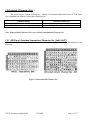
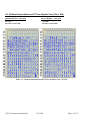
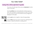
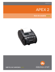
1.2.1 ASCII and Extended International Character Set { 0x80..0xFF}
ESC-‘F’-‘1’ command string selects the International character set. Printer defaults on this character set on
power up.
Figure 1.0 International Character Set
3750T_Developers_Manual.doc
3/12/2008
Page 5 of 37
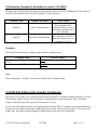
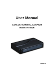
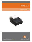
1.2.2 ASCII and Extended PC Line Draw Character Set{0x80..0xFF}
ESC-‘F’-‘2’ command string selects PC Line-draw character set.
Figure 1.2 – PC Line Draw Character Set
2.0 Extech 3750T Printer Font Control
Four commands are defined with the Extech 3750T printer which allow the user to select different typefaces,
change the character height, width as well as add emphasis to the printed text if desired. The following sections
explain in detail how to modify each of the features listed in this paragraph.
2.1 Printer Font Commands to select different character width
Listed below are the fonts installed and the three character command string to select them.
FONT NAME
PITCH
24 CPI normal
COLUMNS PER
LINE
72
CHARACTER
SIZE (WxH)
8x23
SOFTWARE
COMMAND
ESC+'k'+'5'
Courier Mode 5
Courier Mode 4
21 CPI normal
64
9x23
ESC+'k'+'4'
Courier Mode 3
19 CPI normal
57
10x23
ESC+'k'+'3'
Courier Mode 2
16 CPI normal
48
12x23
ESC+'k'+'2'
Courier Mode 1
12 CPI normal
36
16x23
ESC+'k'+'1'
Courier Mode 0
13 CPI rotated
24 (rows per line)
14x16
ESC+'k'+'0'
MSP Font Mode 4
36
ESC+'F'+'4'
MSP Font Mode 5
48
ESC+'F'+'5'
MSP Font Mode 6
57
ESC+'F'+'6'
MSP Font Mode 7
64
ESC+'F'+'7'
MSP Font Mode 8
72
ESC+'F'+'8'
MSP Font Mode 9
96
ESC+'F'+'9'
Table 2.0 – Installed Fonts
Note: Default printer settings are set to 16 CPI 48 columns per line.
3750T_Developers_Manual.doc
3/12/2008
Page 6 of 37
2.2 Character Height Control Commands
A single byte control command is defined to control the printed character height. Normal height of a character
is 23 . EXTEND control character ( ^ \)selects a double height which is equal to 46 . EXTEND OFF control
character (^ ] )selects a normal height. The command is applied to all the characters on a line following the
control character.
Character
Control Hex/Dec
EXTEND
^\
EXTEND OFF
^]
Control Action
Extended Print
0x1C/28
All characters following this command are printed double high.
Extended Print Off/Normal Print
0x1D/29
All characters following this command are printed normal height.
Table 2.1 – Height Control Commands
Note: Default printer settings are set to Normal Print.
2.3 Character Bold/Emphasized Print Control Commands
A line of text using a resident font may be emphasized with the three character commands from the table below.
Command String
Action Taken
Enable emphasized print starting with the current text line
Esc – ‘U’ – ‘1’
Disable emphasized print starting with the current text line.
Esc – ‘U’ – ‘0’
Table 2.2 – Character Emphasis Print Control
Note: Default Printer Settings are set to Esc – U - 0
2.4 Line Spacing Commands
To set the line spacing between successive printed text lines and the number of line feeds desired at the
beginning of a line , use the three character commands from the table below. It is important to mention that
while printing PC Line-Draw characters , the line spacing must be set to zero, thus allowing graphic characters
on successive lines to be connected.
Command String
Command Description
Esc – ‘a’ - n
Where n is the number of graphic-line-spacing, in increments of
0.125 mm. n = { 0..10}
Esc – ‘J’-n
Where n is the number of desired 0.125mm graphic line feeds n =
{0..255}.
Table 2.3 – Character Line Spacing
Note: Printer default setting is 3-dot line spacing after each printed text line. Please note that when a
character has the ‘’ around it , this means that it has to be types exactly as shown. On the other hand
characters that don’t have the ‘’ around it like the “n” in the example above have to be entered while the Alt
key on the keyboard is being held.
3750T_Developers_Manual.doc
3/12/2008
Page 7 of 37
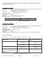
2.5 Underline Command ( Available on version 118v140U)
The following section describes the function of the underline feature for the S3750THS printer. This feature is
available on per character basis and can be applied to a single character.
Command Name
Command Description
Esc F w
Selects Underline Mode
Esc F h
Deselects Underline Mode
Action Taken
All characters following
this command will be
underlined until the Esc F h
command or until the end of
the current line.
All characters following
this command will NOT be
underlined until an Esc F w
command is received.
Examples:
The table below demonstrates examples of the underline command usage.
Command String
Esc -‘F’- ‘w’ – ‘12345’ Esc - ‘F’ – ‘h’
12345
Esc - ‘F’ - ‘w’ – ‘1234567’- CR- ‘12345’
Generated Output
1234512345
1234567
12345
Note:
Please note that the ‘’ and the – characters are not part of the command string.
3.0 8-Bit Dot Addressable Graphic Commands
The Extech 3750T printer uses a single line thermal head, which has 576 heating elements pitched at 0.125 mm.
The total print width is 48 mm. The 8-bit graphic commands enable control of each one of the 576 heating
elements and advancing of the paper by increments of 0.125 mm.
To select the 8-bit graphic mode the user application must issue the ESC-V command, next the host application
sends two bytes to indicate the number of the graphic lines desired, followed with a packet of 72 bytes for each
graphic line. The printer prints the graphic line and advances to the next line automatically.
3750T_Developers_Manual.doc
3/12/2008
Page 8 of 37
3.1 8- Bit Dot addressable Graphic Commands
The following table displays the 8-bit dot addressable graphic commands and the printer actions. It also
illustrates the Commands with an example. Please note that characters <> ‘’ and ‘-‘ are not part of the
command string.
Command String
Esc-’V’-n1-n2
Esc-’J’-n
Esc-V-0x01-0x00
Printer Action
8-bit Graphic mode is selected.<n1> and <n2> is a 16 bit integer indicating the number of graphic lines of
72 characters each to be received. Valid Graphic character sets are from 0x00 to 0xFF Hex using bits 0-7.
Performs <n*0.125mm> feed.
’72 bytes of data’ This code prints a single line of graphic.
Table 3.0 – 8-bit Dot addressable Graphic Commands
3.2 8-Bit Compressed Graphic Commands
The 2 tables below describe the command used to print compressed graphics as well as explain in detail each of
the components of the command string.
Command String
Esc-’v’-height-width-counter-data-counter-data….
Printer Action
Prints a compressed graphic with the specified
attributes.
Table 3.1 – 8-bit Compressed Graphic Commands
Graphic String
Component
Function of the component
An eight bit value representing the number of dot-lines contained in the following
data set
WIDTH
An eight bit value representing the number of bytes to be contained in each dot-line
(# of bytes in each line) of the following data set
An Eight bit value which describes how the following data will be processed
{127 ≥ Counter ≥ 0 } Process the next (Counter + 1 ) bytes of data as 8 bit graphics.
For Signed Values
{0 > Counter ≥ -128} Repeat the next single byte of data (( -Counter) + 1) times.
COUNTER
HEIGHT(# of lines)
{ 127 ≥ Counter ≥ 0} Process the next (Counter+1) bytes of data as 8 bit graphics
For Unsigned Values
{128 ≥ Counter ≤ 255} Repeat the next Singe byte of data, (( 256 – Counter)+1) times
Table 3.2 - Components of the compressed graphics command string
COMPRESSED GRAPHICS EXAMPLE:
The following graphics data is to be printed:
3750T_Developers_Manual.doc
3/12/2008
Page 9 of 37
This data may be represented in hexadecimal:
0x55
0x55
0x55
0x00
0x00
0x55
0x00
0x55
0xAA
0x55
0x11
0x55
The RLE compressed graphics command:
ESC ‘v’ height width counterdata…
DEC 27 118 2
6
255
85
255 0
3
170 17 85 0
253 85
HEX 0x1B 0x76 0x02 0x06 0xFF 0x55 0xFF0x000x030xAA0x110x55 0x000xFD 0x55
3.3 A quick Review of Graphic Logo Commands
Graphic Images can be stored in the form of a logo. This allows the printer to store them in memory locations
and print them as needed. The Extech 3750T printer currently supports 8 logos. Single Byte Command is used
to select a specific logo location. In the commands below ‘n’ can be any number from 0 – 7. For more detailed
description of the Graphic Logo Commands please refer to the Flash Logo Commands section in this
document.
Command
Command Description
Printer Response
Esc – ‘D’-‘L’-n
Esc – ‘L’-‘G’-n
Esc- ‘L’-‘G’-<0xFF>
Esc-‘L’-‘g’-n
Select Flash Logo Mode
Load/Record Graphic Logo
Stop Loading Graphic Logo
Print Graphic Logo
?
none
D!X
Printer Prints Logo n
Table 3.3 – Graphic Logo Commands
4.0 Bar Codes
The Extech 3750T printer supports several bar code symbologies. Two commands are defined for printing bar
codes.
Bar Code Command Formats
Printer Action
Esc- ‘z’-n1-n2-L-[data]
Prints Bar code only
Esc- ‘Z’-n1-n2-L-[data]
Prints Bar code
and ASCII visible
n2
Command String Components
bar code type
‘1’ Code 39
‘2’ Code 128,UCC/EAN-128
‘3’ Interleaved 2 of 5
‘4’ UPC/EAN/JAN
‘5’ Codabar
number of character bytes in data array 1-255
L
Height of bar code printed in increments of 0.125mm
n1
Table 4.0 – Bar Code Command Formats
3750T_Developers_Manual.doc
3/12/2008
Page 10 of 37
All barcodes are printed with the minimum bar width ( “x-dimension”) of 0.250mm, in compliance with the
respective official specification.
4.1 Code 39 specifications
Description:
Each symbol starts with Leading Quiet Zone, followed with Start Symbol, Data Symbols,
ending with Stop Symbol and Trailing Quiet Zone.
Character set:
36 alphanumeric (0-9, A-Z) and '-' 'space' '$' '/' '+' '%'
Note: Only capital letters are supported.
Elements per symbol:
9 (5 bars, 4 spaces)
Character density: 6.25 CPI
Bar width:
0.25mm (narrow to wide ratio of 1:3).
Characters per line: 12 with auto center (maximum).
Command String
Printer Output
Esc-‘Z’-‘1’-0x07- 0x0a-‘CODE-39’
Prints CODE -39, 1mm high
Table 4.1 – CODE 39 Example
4.2 Code 128 specifications
Description:
Each symbol starts with Leading Quiet Zone, followed with Start Symbol, Data Symbols,
ending with Stop Symbol and Trailing Quiet Zone.
Character set:
Support for full 256 ASCII set among three subsets.
Elements per symbol:
6 (3 bars, 3 spaces)
Character density: 9.1 CPI
Bar width:
0.25mm
Characters per line: 18 alphanumeric characters , or 36 numeric only (maximum) - automatically centered.
Code 128 Start character:
<start character> = {0x87, 0x88, 0x89} determines the character set to be printed
Start Character
Characters Sent to Printer
IF <start character> is 0x87 CODE
A
0x020 through 0x03F ASCII
(#32 - #63)
Characters Read by Bar Code
Reader
0x020 through 0x03F ASCII
(#32 - #63)
0x040 through 0x07F ASCII
0x00 through 0x07F ASCII
(#64 - #127)
(#0 - #31)
0x020 through 0x07F ASCII
0x020 through 0x07F ASCII
(#32 - #127)
(#32 - #127)
PAIRS 0x030 through 0x039
PAIRS 0x030 through 0x039
ASCII
ASCII
(#48 - #57)
(#48 - #57)
IF <start character> is 0x88 CODE
B
IF <start character> is 0x89 CODE
C
(Each number must be paired with
another)
Table 4.2 – Code 128 Start Character
3750T_Developers_Manual.doc
3/12/2008
Page 11 of 37
Code 128 Data Bytes:
<DATA>
The data bytes are defined by which character set is defined. The printer accepts all characters 0x20h - 0x7Fh
with the translations defined above.
Also, characters 0x080 - 0x86 may be used as code 128 control characters:
HEX
DEC
CODE A
CODE B
CODE C
0x080
128
FNC 3
FNC 3
0x081
129
FNC 2
FNC 2
0x082
130
SHIFT
SHIFT
0x083
131
change to C
change to C
0x084
132
change to B
FNC 4
change to B
0x085
133
FNC 4
change to A
change to A
0x086
134
FNC 1
FNC 1
FNC 1
Table 4.3 – Code 128 Data Bytes
FNC 1: reserved CODE 128 character (used for UCC/EAN128)
FNC 2: message append (not supported by all bar code readers)
FNC 3: Initialize bar code reader
FNC 4: extend characters (bar code reader reads character + 128)
For example: 'a' is changed from #97 to #97+128 = #225
Notice: It is possible to switch code sets in the middle of the bar code. This is useful with heavily numeric
alphanumeric bar codes (see example below).
Code 128 EXAMPLES:
Print alphanumeric bar code "A2a", 12.5mm high, with human readable text:
n = 3 printed characters + 1 start character = 4
L = 12.5mm / 0.125mm = #100
start character = START B (full ASCII alpha numeric) = #136
#27
0x1B
ESC
#90
0x5A
‘Z’
#50
0x32
‘2’
#04
0x04
0x04
#100
0x64
‘d’
#136
0x88
0x88
#65
0x41
‘A’
#50
0x32
‘2’
#97
0x60
‘a’
Print all-numeric bar code "1234", 5mm high, without human readable text:
n1 = 4 printed characters + 1 start character = 5
L = 5mm / 0.125mm = #40
start character = START C (numeric pairs) = #137
#27
0x1B
ESC
#122
0x7A
‘z’
#50
0x32
‘2’
#05
0x05
0x05
3750T_Developers_Manual.doc
#40
0x28
‘(’
#137
0x89
0x89
3/12/2008
#49
0x31
‘1’
#50
0x32
‘2’
#51
0x33
‘3’
#52
0x34
‘4’
Page 12 of 37
4.2.1 UCC/EAN-128 specifications
Description:
The UCC/EAN-128 specification is an internationally recognized format for application
identifiers in code 128 bar codes. The bar code symbology is identical to Code 128.
These identifiers are not intended for point-of-sale applications. Only recognized bodies
of the UCC or EAN may assign application identifiers. More information may be found
at:
http://www.ean.be/ for the EAN and
http://www.uc-council.org/ for the UCC
EAN 128 EXAMPLES:
Print all-numeric bar code "1234", 5mm high, with human readable text in EAN-128 format:
n1 = 1 start character + EAN specified + 4 printed characters = 6
L = 5mm / 0.125mm = #40
start character = START C (numeric pairs) = #137
#27
0x1B
ESC
#90
0x5A
‘Z’
#50
0x32
‘2’
#06
0x06
0x06
#40
0x28
‘(’
#137
0x89
0x89
#134 #49
0x86 0x31
FNC1 ‘1’
#50
0x32
‘2’
#51
0x33
‘3’
#52
0x34
‘4’
4.3 Interleaved 2 of 5 specifications
Description:
Each symbol starts with Leading Quiet Zone, followed with Start Symbol, Data Symbols,
ending with Stop Symbol and Trailing Quiet Zone.
Character set:
numeric pairs.
Elements per symbol:
10 (5 bars, 5 spaces)
Character density: 11.11 CPI
Bar width:
0.25mm
Characters per line: 24 numeric (maximum), automatically centered.
Example:
Command String
Esc- ‘Z’-‘3’- 0x0A – 0x50 – ‘1234567890’
Printer Output
Prints interleaved 2 of 5 “
12345678” , 10 mm high
Table 4.4 – Interleaved 2 of 5 - Example
3750T_Developers_Manual.doc
3/12/2008
Page 13 of 37
4.4 UPC/EAN/JAN specifications
Description:
Each symbol starts with Leading Quiet Zone, followed with Left Guard Bars, Left Data
Symbols, Center Bar Pattern, Right Data Symbols, Check Character, ending with Right
Guard Bars and Trailing Quiet Zone.
The UPC, EAN/JAN-8, EAN/JAN-13 specifications comprise an internationally
recognized format for application identifiers. Unlike the UCC/EAN-128 specification,
these identifiers are intended for point-of-sale applications. Only recognized bodies of
the UCC and EAN may assign application identifiers. More information may be found
at:
http://www.ean.be/ for the EAN and
http://www.uc-council.org/ for the UCC
Character set:
numeric - fixed length.
Elements per symbol:
4 (2 bars, 2 spaces)
Character density: 14.5 CPI
Bar width:
0.25mm
Characters per line: UPC-A:
11 - plus check digit (automatically centered).
UPC-E:
6 - plus check digit (automatically centered).
EAN/JAN-8:
7 - plus check digit (automatically centered).
EAN/JAN-13:
12 - plus check digit (automatically centered).
Examples:
Command String
Printer Output
Esc – ‘Z’- ‘4’ – 0x0C-0xB8 - ‘123456789’
Prints UPC- A “123456789”, 23 mm high
Esc – ‘Z’-‘4’-0x07-0xB8 – ‘0783491’
Prints UPC-E “0783491”, 23 mm high
Esc-‘Z’-‘4’-0x08-0xC8-‘65432109’
Prints EAN/JAN-8 “65432109”, 25 mm high
Esc-‘Z’-‘4’-0x0D-0xA0 – ‘6543216543219’
Prints EAN/JAN – 13 “6543216543219”, 20 mm high
Table 4.5 - UPC/EAN/JAN Examples
Note: in all the examples where ‘9’ is the last digit to be sent the received check digit ‘9’ is ignored and
recalculated in the printer. Also all heights are total height, including a 1.23mm drop bar pattern printed
after the bar code pattern.
4.5 Codabar Specifications
Description:
Each symbol starts with Leading Quiet Zone, followed with Start Symbol, Data Symbols,
ending with Stop Symbol and Trailing Quiet Zone.
Character set:
0-9, {$, -, :, /, ., +} and start/stop pairs {A/T, B/M, C/*, D/E}
Elements per symbol:
7 (4 bars, 3 spaces)
Character density: 8.1 CPI
Bar width:
0.25mm
Characters per line: 20 (maximum) plus start/stop, automatically centered.
3750T_Developers_Manual.doc
3/12/2008
Page 14 of 37
Examples:
Command String
Printer Output
Esc-‘Z’- ‘5’-0x0A-0x78-‘A123456T’
Prints Codabar “123456” , 15 mm high using the A start character
Esc-‘Z’-‘5’-0x06-0x50-‘C2468*’
Prints Codabar “2468” , 10 mm high using the C start character
Table 4.6 – Codabar examples
5.0 Print Contrast Control
The contrast of the printed text or graphics depends on the type of the thermal paper used, the printer
battery voltage and the printer contrast setting selected by the host application.
Ten levels of printer contrast settings are supported. This feature insures operation with different grades
of thermal paper available. The printer defaults to the middle contrast. The contrast may be changed by the host
application, using the <Esc-‘P’- n > command string.
During the printing process, the battery voltage and the thermal head temperature are monitored. The
print contrast is adjusted to assure consistent printout. The print speed is affected by the contrast setting; fastest
print speed is achieved if the contrast is set to 9.
5.1 Print Contrast Control Command
Print Contrast Control Command String
Esc-‘P’-‘n’
Description of String Components
n= ASCII ‘0’ through ‘9’ { 0x30..0x39}
‘0’ Highest contrast and lowest print speed
‘9’ Lowest contrast and highest print speed
Table 5.0 – Print Contrast Control Command
Note: Default setting is Esc-‘P’ – ‘5’
5.2 Printer Peak-Power Control Command
The peak power control commands enable the operation of the printer with wide range of battery chemistries
and peak capacities.
The printer may be operated in five peak-power modes, as listed in the table below
Power Mode
1- Low
2- Medium
3- High
Command
Maximum Dots Selected
Maximum Current
Esc-‘P’-0x01 Heat < 64 elements at a time
Less than 1.0 Amp
Esc-‘P’-0x02 Heat <128 elements at a time
Less than 2.0 Amps
Esc-‘P’-0x03 Heat < 192 elements at a time
Less than 3.0 Amps
4- Very High
Esc-‘P’-0x06 Heat < 576 elements at a time
Less than 9.0 Amps
5- Auto Control Esc-‘P’- 0x07 64,128,192, or 576 at a time
1.5 to 3.0 Amps
Table 5.1 – Printer Peak Power Control Command
3750T_Developers_Manual.doc
3/12/2008
Page 15 of 37
The printer default is Auto Control Mode. While in auto-peak-power mode, printer counts the number of dots
to be fired and selects the appropriate power mode depending on the available battery capacity. The peakpower setting directly affects the printing speed; printing is slowest for Low peak-power mode.
Note: The on-board brownout circuit resets the printer controller, if peak-power usage exceeds the batteries
power capacity
5.3 Printer Battery Voltage Monitor Commands
The battery voltage level may be printed or polled by the host device application using the ESC – ‘P’ '^' or <CTRL V> command strings, respectively.
Command String
Esc – ‘P’- ‘^’
CTRL V
Printer Response
Prints Battery Voltage
Transmit Battery Voltage
Table 5.2 – Printer Battery Voltage Monitor Commands
5.4 Auto Power Down Command
In order to conserve battery life the printer features an auto power down timer. The power down timer defaults
to 20 seconds on initial power up.
The auto power down timer may be set or disabled by sending recognized command strings. The auto power
down is re-started on every character received.
The auto power down timer may be disabled by activating the <RTS> input line, or setting the auto power down
timer to zero, the printer lowers the CTS output line and transmits Auxoff followed with Xoff before power
down.
Command String
Printer Response
Esc-‘M’-‘n1’ – ‘n2’ – ‘0’-‘CR’
Sets the printer Auto power down timer (.n1 and n2
may be ‘0’ to ‘9’)
Esc – ‘C’
Resets The Auto Power down to 20 seconds
Table 5.3 - Auto power down commands
Auto Power Down Command Examples:
Command String
Printer Response
Esc – ‘M’ – ‘0’- ‘0’- ‘0’ – ‘CR’
Disable the power out timer
Esc – ‘M’- ‘9’ – ‘9’ – ‘0’ – ‘CR’
Set the timer to 99 seconds
Table 5.4 – Auto Power Down Command Examples
3750T_Developers_Manual.doc
3/12/2008
Page 16 of 37
5.5 Printer Operating Mode Commands
The printer can be operated in two modes, Online or Buffer modes. In online mode, the characters are
printed as they are received. In buffer mode, the characters received are stored in the print buffer and printed
upon receipt of EOT character(^D).
Command String
Esc-‘P’-‘#’
Esc-‘P’-‘$’
Selected Mode
Selects Online Mode
Selects Buffer Mode
Table 5.5 – Printer Operating Mode Commands
5.6 Supervisory commands
Single byte supervisory commands are designed to provide the user of the printer with the current
battery and print buffer status. The single byte supervisory commands and serial RS232 response strings are
summarized below.
Note: <4 ASCII hex digits> are read as hex nibbles ORed with 0x30.
Printer Command
Command String
Printer Response
Print Buffer Status
Print Status Request
<CTRL B>
Magnetic Card Reader
Status
Print Buffer Status
Battery Status Request
<CTRL V>
Battery Voltage Status
Magnetic Card Reader
Status
Firmware Version
Firmware Version Query
<ESC><’P’><’(‘>
Example v1.00
Hardware Version
Hardware Model Query
<ESC><’P’><’)’>
Disable EOT response
<ESC><’P’><’+’> response
Enable EOT response
<ESC><’P’><’-’>
EOT
^D/0x04
Disable
Buffer
Empty
Enable
Buffer
Empty
response
(printer ready for more data)
Buffer Empty Response
<Esc><‘B’>
<4 ASCII hex digits> <CR><LF>
<Esc> <’M’>
<4 ASCII hex digits> <CR><LF>
<Esc><‘B’>
<4 ASCII hex digits> <CR><LF>
<Esc><‘V’>
<4 ASCII dec digits> <CR><LF>
<Esc><‘M’>
<4 ASCII hex digits> <CR><LF>
<Esc> <’(‘>
<4 ASCII characters><CR><LF>
<Esc ><’(‘>
<’1’ ‘0’ ‘0’ ‘’ > <CR><LF>
<ESC><’)’>
<4 ASCII characters> <CR><LF>
NONE-EOT (^D) is not transmitted
EOT (^D) transmitted on buffer empty
Transmitted if printer buffer empty and the
printer is ready for more data.
Table 5.6 – Supervisory Commands
3750T_Developers_Manual.doc
3/12/2008
Page 17 of 37
6.0 Label and Form Printing With Black Mark Option
The Extech 3750T thermal printer can print on label and preprinted form stocks, with black mark located on the right
side of the paper stock. The printer paper out sensor is used to sense the black mark position.
6.1 Black Mark Operation
Follow these steps to use the black mark option.
• Set the paper out sensor sensitivity level by issuing <ESC> <‘Q’> <‘Q’> <n> command string. The value selected
for the sensitivity is dependant upon the height of the pre-printed black mark located on the label or form stock.
The default power on value of <n> is 40d (0x28).
• Issue <ESC> <‘Q’> <‘F’> <m> or <ESC> <‘Q’> <‘B’> <m> printer Command to find the black mark. The command
position’s the label or the form for printing.
• Wait for <ESC> <‘Q’> <0x3F> <0x3F> <n1> <n2> black mark found response from the printer.
• Send the data to be printed.
6.2 Black Mark Printer Commands
Black Mark Command
Reverse Dot Feed
<ESC> <‘Q’> <‘J’> <n>
Command String
Out of Paper Sensitivity
<ESC> <‘Q’> <‘Q’> <n>
Forward Black Mark Seek
<ESC> <‘Q’> <‘F’> <m>
Reverse Black Mark Seek
<ESC> <‘Q’> <‘B’> <m>
Printer Black Mark
Response:
<ESC> <‘Q’> <0x3F>
<0x3F> <n1> <n2>
Printer Black Mark
Response:
<ESC> <‘Q’> <0x30>
<0x30> <n1> <n2>
Paper Found
Paper Not Found
Description
Perform <n> reverse dot line feeds,
0.125mm each.
On paper detect fail, postpone the paper
out error response for <n> 0.125mm dot
lines before flagging a paper out error.
Seek black mark using forward feed until
<m> dot line feeds have been processed,
each dot line feed 0.250mm.
Seek black mark using backward feed until
<m> dot line feeds have been processed,
each dot line feed 0.250mm.
n1 and n2 are the high and the low nibble,
respectively, describing how many
(0.25mm) dot lines were required to find
black mark.
n1 and n2 are the high and the low nibble,
respectively, describing how many
(0.25mm) dot lines were processed before
reporting black mark status.
Notes:
<n> Total number of 0.125mm dot lines, 0x00 through 0xFF.
<m> Total number of 0.250mm dot lines, 0x00 through 0XFF.
n1 and n2 The total number of 0.125mm dot lines processed, while seeking the black mark.
n1 holds the high four bits (0x30 + 4 high bits).
n2 holds the low four bits (0x30 + 4 low bits).
n1 and n2 can have values 0x30 through 0x3f.
Table 6.0 – Black Mark Printer Cmmands
3750T_Developers_Manual.doc
3/12/2008
Page 18 of 37
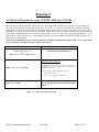
Appendix A
A.1 Flash Font Download for model 2500THS/1500T and S3750 THS
The major difference between the table organization in the 3500T/THS and the 2500/1500 and 3750 is that in the 3500 there are
banks and tables while in the second group of printers there are no tables – only banks. Another difference is that the ASCII and
extended tables for each font are place right one after another and that is why it does not matter if you send Esc D A or ESC D X in
the beginning. As long as you specify the correct location the desired character or font will get downloaded in the right spot. Both the
ASCII and the Extended characters for each font are in this big table so to say. You only need to specify the bank number ( 0..7) – no
table number is needed. You still have to send a number for the table just so the command is consistent all through the models – the
number however is disregarded.
To protect the installed fonts from accidental corruption, the Flash Font commands described in Table 7.4 are required to be
the first commands received by the printer when it is powered on.
Command
2500THS/1500T and 3750 THS
<ESC> <‘D’> <‘A’> <n>
Or
<ESC ><’D’><’X’> <n> Where n (0..7)
Select flash font Download mode
Upload an ASCII character.
<ESC> <‘D’> <n1> <n2> <data>
n1: TABLE to save the character in. This is still kept for
compliance with the old command but the table number is
disregarded by the printer.
n2: Character code ( Shows the beginning position to
download in the table)
{0x21 .. 0x7F} {CHR$(33) .. CHR$(127)}
<ESC> <‘D’> <0xFF>
Save the font uploaded and terminate font upload
process,
Table A.1 - Flash Font Upload commands
3750T_Developers_Manual.doc
3/12/2008
Page 19 of 37
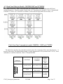
A.2 Flash Font Tables for Models 2500THS/1500T and S3750THS
Flash fonts are stored in 7 banks. Each bank holds one complete table ( The table holds both ASCII and
extended characters) . Thus for example Courier Font 1 & 2 International is in bank 0, Courier 3 International
is in Bank 1, Courier 1 & 2 Line Draw is in Bank 4 ( notice that the empty banks do not count)., etc.
Flash Font Print Commands for models 2500THS , 3500T and 3750THS
The table below describes the commands needed to print with a certain font. Please note that character ‘-‘ is
not part of the string. The default Printer setting is Courier International 21CPI ( decimal code 27 107 4). These
commands are valid for 1500/2500, 3500T, 3750 and 4500THS.
Font Name
Courier International
12 CPI & 16 CPI
(Esc – F1)
International
Font Type
Command String
3750T_Developers_Manual.doc
Courier International
19 CPI
Font Print
Command
Esc-k-1 Prints 12 CPI
Esc–k-2 Prints 16 CPI
Esc – k – 3
Prints 19 CPI
File Name
of File to
restore
Factory
Font
EX-GRP12.DWN
EX-GRP10.DWN
Esc-k-4 Prints 21 CPI
Courier International
21 CPI & 24 CPI
3/12/2008
Esc-k-5 Prints 24 CPI
EX-GRP08.DWN
Page 20 of 37
Rotated Courier
International
(Esc –F2)
Graphic
Courier Graphic 12
CPI & 16 CPI
Courier Graphic 19
CPI
Courier Graphic 21
CPI & 24 CPI
Rotated Courier
Graphic
Esc-k-0
Esc-k-1 Prints 12 CPI
Esc-k–2 Prints 16 CPI
Esc–k–3Prints 19 CPI
Esc–k–4 Prints21 CPI
Esc–k–5 Prints24 CPI
EX-INT12.DWN
EX-INT10.DWN
EX-INT08.DWN
Esc-k-0
Table A.2 - Flash Font Print Commands
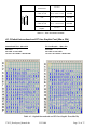
A.1.3 Default International and PC Line Graphic Font (08w x 23h)
International Font - 08w x 23h
Command string to Select:
esc-<F1>
esc-<k4> or esc-<k5>
PC Line Graphic - 08w x 23h
Command string to Select:
esc-<F2>
esc-<k4> or esc-<k5>
File Name: TB-A-08.DW2 + TBXn0823.DW1
File Name: TB-A-08.DW2 + TBXi0823.DW1
Table A.3 - Default International and PC Line Graphic Font (08x23h)
3750T_Developers_Manual.doc
3/12/2008
Page 21 of 37
A.1.4 Default International and PC Line Graphic Font (10w x 23h)
International Font - 10w x 23h
Command string to Select:
esc-<F1>
esc-<k3>
File Name: TB-A-10.DW1 + TBXn1023.DW1
PC Line Graphic - 10w x 23h
Command string to Select:
esc-<F2>
esc-<k3>
File Name: TB-A-10.DW1 + TBXi0823.DW1
Table A.4 - Default International and PC Line Graphic Font (10x23h)
3750T_Developers_Manual.doc
3/12/2008
Page 22 of 37
A.1.5 Default International and PC Line Graphic Font (12w x 23h)
International Font - 12w x 23h
Command string to Select:
esc-<F1>
esc-<k1> or esc-<k2>
PC Line Graphic - 12w x 23h
Command string to Select:
esc-<F2>
esc-<k1> or esc-<k2>
Table A.5 - Default International and PC Line Graphic Font ( 12x23h)
3750T_Developers_Manual.doc
3/12/2008
Page 23 of 37
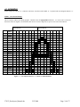
A.1.6 EXAMPLE:
In this example the character ‘A’ (character code 0x41) stored in ASCII TABLE ‘0” is replaced with user designed character ‘A’.
STEP 1 – Describe the Bitmap:
This is best done within a font-editing program. Characters must be right justified within the 16 x 23 bit cell. To ensure the
characters do not run together, care should be taken to leave at least a single line of space on one side of each character.
Line
Value
(HEX)
1
2
3
4
5
6
7
8
9
10
11
12
13
14
15
16
17
18
19
20
21
22
23
00 00
00 40
00 E0
00 A0
01 B0
01 10
01 10
01 10
01 10
03 18
03 18
03 F8
03 F8
02 08
02 08
06 0C
06 0C
04 04
04 04
04 04
0E 0E
0E 0E
00 00
‘LEFT BYTE’
80 40 20
10
8
4
2
1
16
13
12
11
10
9
15
14
X
X
x
x
x
x
x
x
x
X
X
X
X
X
X
X
X
‘RIGHT BYTE’
80 40 20 10
x
x
x
x
x
x
x
x
x
X
X
8
x
x
x
x
x
7
X
X
X
X
6
x
x
x
x
x
5
x
x
x
x
x
x
x
x
x
8
4
2
1
4
3
2
1
x
x
x
x
x
x
x
x
x
x
x
x
x
x
x
x
x
x
x
Figure 7. 1 – User defined character ‘A’ drawn as 12Wx23H matrix.
3750T_Developers_Manual.doc
3/12/2008
Page 24 of 37
STEP 2 – Enter flash font program mode:
Send <ESC> <‘D’> <‘A’> <0> to select ASCII flash font upload and wait for the printer to deactivate the CTS line. For the 2500 or
the 3750 printers the last number can be anything between 0..7
STEP 3 – Wait for the printer ready indicators:
Wait for the printer to reactivated the CTS line and transmitted the character ‘?’
STEP 3 – Load new the character:
Upload the user defined ASCII ‘A’ character.
The basic command format and an actual command string are shown below:
<ESC> <‘D’> <ASCII TABLE 0> <Character Code> <46 byte dot matrix data> //for the 3750 or 3750 the table # does not
matter as long as you specified the bank number.
<ESC> <‘D’>
<0>
<0x41>
<0x00> <0x00>
<0x00> <0x40> <0x00> <0xE0> <0x00> <0xA0>
<0x01> <0xB0> <0x01> <0x10> <0x01> <0x10> <0x01> <0x10>
<0x01> <0x10> <0x03> <0x18> <0x03> <0x18> <0x03> <0xF8>
<0x03> <0xF8> <0x02> <0x08> <0x02> <0x08> <0x06> <0x0C>
<0x06> <0x0C> <0x04> <0x04> <0x04> <0x04> <0x04> <0x04>
<0x0E> <0x0E> <0x0E> <0x0E> <0x00> <0x00>
STEP 5 – Save the modified character to flash:
Sending the command <ESC>-‘D’- <0xFF> {CHR$(27) + ‘D’ + CHR$(255)}, copies the revised character to the printer flash
location.
The printer will transmit the character ‘D’ and then proceed to save the fonts to flash memory. THE PRINTER POWER MUST
REMAIN ACTIVE AT THIS TIME.
STEP 6 – Cycle the printer power:
Once the fonts have been saved into flash memory, the printer will transmit the character ‘!’.
At this time, the printer will transmit an ‘X’ every 500 milliseconds.
To ensure optimal operation of the printer, remove the battery cartridge from the printer for several seconds. Replace the battery
cartridge and the new fonts will be ready for use.
To ensure optimal operation of the printer, remove the battery cartridge from the printer for several
seconds. Replace the battery cartridge and the new fonts will be ready for use.
3750T_Developers_Manual.doc
3/12/2008
Page 25 of 37
A.2.0 Graphic Logo Print Option
The following paragraphs summarize the operation of the Graphic Logo feature for the Extech S3750THS
printer. The Graphic Logo feature enables the storage of formatted Bitmap file in nonvolatile memory. Up to
eight memory sectors of up to 12,816 bytes each, are reserved to store Graphic Logo in the printer Upon receipt
of a Graphic Logo print command, the Graphic Logo data is sent to the printer. The feature enables printing of a
stored graphic image as part of a receipt.
Specification
Printer
Number of
Logos
8 (FLASH)
n =(0..7)
3750
Bytes per
logo
Dot lines per
logo
Dots per line
12,816
178
576
Graphic Logo Operation S3750THS
•
On initial power-up, the Host application selects the Flash Logo Mode by sending the command String:
<ESC - D – L -n>.
Printer responds by sending ? character to the host application indicating that the Flash Logo Mode is enabled.
•
The Host application selects the Graphic Logo record mode by sending the load command:
<ESC - L - G - n>.
•
Once printer is placed in record mode, the Graphic Logo is downloaded using 8-bit graphic command:
<ESC> <V> <0x01> <0x00> <72 bytes of Graphic data>
•
The Graphic Logo record mode is terminated automatically after receiving 178 graphic lines, or
upon receiving the Graphic Logo record terminate command string.
ESC - L - G - < 0xff >
•
Printer saves the received Logo data in flash and sends D!X characters to the host, indicating that logo data was saved.
The printer power must be cycled to return to normal operating mode.
Command
Esc – D-L-n
Esc – L-G-n
Esc- L-G-<OxFF>
Esc-L-g-n
Command Description
Select Flash Logo Mode
Load/Record Graphic Logo
Stop Loading Graphic Logo
Print Graphic Logo
Printer Response
?
none
D!X
Printer Prints Logo n
Please note: The characters ‘-‘ , ‘<’ or ‘>’ are not part of the command string. Decimal code for Esc is (27).
3750T_Developers_Manual.doc
3/12/2008
Page 26 of 37
Generating Graphic Logos
To generate the graphic logo follow these steps:
•
•
Install the Extech windows printer driver
Use Wordpad or any Windows application to prepare your logo document
From printer Setup of Wordpad application Set the paper margins to 0.12”.
•
Print your logo document to a file, name it <LOGO.PRN>, using The Extech Windows driver.
3750T_Developers_Manual.doc
3/12/2008
Page 27 of 37
Go to DOS Window and start the EDIT program.
Go to Start and then select RUN and in the RUN window type EDIT and press ENTER. The program will open.
• Open <LOGO.PRN> file in BINARY mode.
Press <Ctrl> <Home> to place cursor at the beginning of file.
Delete everything in the beginning of the file up to but not including the arrow and the capital letter V next to it.
Move cursor to the end of the file, by pressing control End on your keyboard, There you will see 2 characters - a character which
resembles a circle with a cross attached to it (the FF character) and the line feed character. Delete these two characters. Add the
LOGO RECORD END command string by typing Esc LG 255. If you never worked with the EDIT program here is how you have to
type it. Press CTRL key and the letter P . Then press the Esc key. Then type LG and then press the ALT key and type 255.
•
Save the modified <logo.prn> file.
Uploading Graphic Logos
To copy the Logo file to the printer follow these steps:
•
Use a serial communication program like Telix, Procomm or Windows HyperTerminal or Tera Term.
•
Check that the application is set to the same baud rate and parity as the printer.
•
Upload the LOGO.PRN file to the printer using a BINARY file transfer protocol. Follow these steps to
upload a logo file. Please note that all commands have to be typed exactly as shown because the
software is case sensitive.
1) Cycle the power of the printer
2) Type Esc- D-L-n ( This shows the location where you want to download the logo 0..7)
3) Wait until a question mark comes back from the printer
4) Type Esc L-G-n ( can be any number and does not affect the logo download location)
5) Send the logo file which you have just created
6) Wait for D!X response to come back from the printer. This indicates that file transmission and storage
is completed.
7) Cycle power
8) To test the LOGO.prn file issue print commands : Esc – L – g – n
3750T_Developers_Manual.doc
3/12/2008
Page 28 of 37
Appendix B
Three Track magnetic Card Reader Option
A three track Magnetic Card Reader is available on the Extech 3750T model printers. The MC reader is
designed to read magnetically encoded data from cards conforming to ANSI/ISO 7810, 7811 standards.
The MC reader converts the F2F encoded signals on the magnetic card, to ISO7811 compatible ASCII format
and transmit the information to the host computer or a terminal.
The MC reader can read one, two or three tracks simultaneously and bi-directionally.
Set of printer ESC software commands are supported in order to provide the following operating features:
y Select the MC reader.
y Set the auto time-out software timer
y Report MCR Read errors
y Report MC reader status.
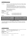
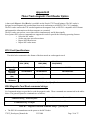
B1.0 Card Specifications
The table below summarizes the format of the data stored on each magnetic track.
Track Position
Recording
Density
Recording
Capacity
Number of data
bits
Card
Thickness
Track 1
ISO1 (IATA)
Track2
ISO2 (ABA)
210 BPI
Track3
ISO3(MINTS)
75 BPI
79 characters
210 BPI
40 characters
7
107 characters
5
7
.76 mm +/- 0.08 mm
Table B.0 – Card Specifications
B2.0 Magnetic Card Read command strings
Six Commands strings are provided, to read the magnetic cards. These commands are summarized in the tables
below. The general syntax for commands are as follows:
Command String – General Syntax
<ESC><’M’><n>< n> Track #CR
<ESC><’M’> ‘9’ ‘ 9’
Command String - Example
1 CR
Table B.1 – Magnetic Card Read Command Strings – general form
The ESC-M command turns on the power to the MC Reader
3750T_Developers_Manual.doc
3/12/2008
Page 29 of 37
The next two bytes, <nn> are used to set the MC reader’s timer. "01" through "99" are valid timer settings
and “00” disables the timer.
The printer aborts and transmits the time-out error message, if the operator fails to swipe a card within the
time period set by the host application.
On timeout printer aborts the swipe process, transmits timeout error message and turns off the <READING>
LED.
A good magnetic card swipe automatically terminates the read process.
Magnetic Card Command String
ESC
ESC
ESC
ESC
ESC
ESC
ESC
–
–
–
–
–
–
–
M
M
M
M
M
M
C
-
nn
nn
nn
nn
nn
nn
-
1
2
3
4
5
6
–
–
–
–
–
–
Description
CR (CR = Enter)
CR
CR
CR
CR
CR
Read Track1 only
Read Track2 only
Read Track3 only
Read Track1 and Track2 simultaneously
Read Track2 and Track3 simultaneously
Read Tracks 1,2 and 3 simultaneously
Cancel MC Read process
nn = ASCII "01" through "99" seconds
nn = “00” disables the MC reader timer
Table B.2 – Magnetic Card Read Command Strings - Details
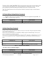
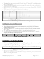
B.3.0 Magnetic Card Data Output Format
The track data retrieved from a magnetic card is transmitted to the host in ISO7811 ASCII format as
summarized in the table below.
The first four characters (“%/1/”) flag the track number, the track data follows the flag string, terminated
with ‘?’-CR-LF.
‘%;+’ are the track start sentinel characters, While ‘?’ is the end of track sentinel character.
If no data is available for a track that data field will be empty. If an Error is encountered on any track a
single ‘E’ will be the output for that tracks data field.
Track1
%/1/
Data
Track 2
?CRLF
;/2/
Data
Track 3
?CRLF
+/3/
Data
?CRLF
Table B.3 - ISO 7811 ASCII Format
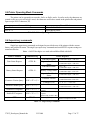
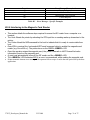
B.4.0 Magnetic Card Read Error Messages
The characters <%> and <E> preface all error messages. Following these two characters is a comma, the
error number in ASCII (01 through 99), another comma, English description of the error encountered and
finally CR-LF terminating the <Error Message> string. The syntax is as follows:
Error Message ( General Form)
y
<%><E>, nn , Error text in ASCII, <CR> <LF>
Table B.4 – Error Message – General Form
Where nn is error number encountered.
The printer may transmit Four (4) types of Read Error messages. The following messages terminated with
CR-LF are returned by the firmware:
3750T_Developers_Manual.doc
3/12/2008
Page 30 of 37
Error #
05
07
08
09
Error Message Transmitted
Time-out Expired
Invalid Track Number
Unsupported Track Selected
Cancel Request
Table B.5 – Error Message – Specific Examples
B.5.0 Interfacing to the Magnetic Card Reader
This section details the software steps required to access the MC reader from a computer or a
terminal.
The Host Selects the printer by activating the RTS input line or sending wake-up characters to the
printer.
The Printer Sends the XON command to the host to indicate that it is ready to receive data from
host.
Once XON is received the host sends ASCII serial command string to enable the magnetic card
reader (e.g. Esc-m004-cr). The printer turns on the GREEN <READY> LED.
Once the operator swipes the magnetic card, the printer transmits in ASCII format the tracks
information found on the magnetic card.
A good read automatically turns off the MC reader and the <READY> LED.
The <READY> LED illuminates RED if an error is encountered, while reading the magnetic card.
Printer transmits timeout error message if the operator fails to swipe a card in the time period set by the host
application.
3750T_Developers_Manual.doc
3/12/2008
Page 31 of 37
Appendix C
Printer Configurations
The 3750T printers support Serial RS232 and IrDA compatible infrared communication interfaces. Blue
Tooth communication is also available as an optional feature. Serial, IrDA and Bluetooth communication
settings can be changed via a DIP switch located on the control card. In the following Sections Each Setting
is discussed in more detail.
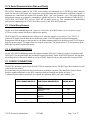
S3750 DIP SWITCH SETTINGS
Dip Switch
1, 2, 3, 6
4, 5
4, 5
6
7
8
Function
Switch #
Switch #
Switch #
Switch #
SW 6
Notes
Communication Interface
SW 1
SW 2
SW 3
RS 232
OFF
OFF
OFF
Also set 4&5
IrDA and RS232
ON
OFF
OFF
9600 baud
IrDA ONLY
ON
ON
OFF
IR Direct Mode
ON
ON
OFF
802.11b and RS232
OFF
OFF
ON
Also set 4&5
ON
9600 baud
Also set 4&5
802.11b ONLY
OFF
ON
ON
Also set 4&5
BT and RS 232
OFF
OFF
ON
Also set 4&5
BT ONLY
OFF
ON
ON
Also set 4&5
Comm. 1 - Baud Rate
SW4
SW5
Serial RS2323 Rate
38,400
OFF
OFF
BT & 802
19,200
OFF
ON
9,600
ON
OFF
2,400
ON
ON
Comm. 2 Baud Rate
SW 4
SW 5
IrDA Rate
9,600
OFF
OFF
Fixed
9600 to 38400 Baud
ON
OFF
Variable
Parity bit
SW 6
Parity Enabled
ON
Parity Disabled
OFF
Odd/ Even
SW 7
Even Parity Checker
ON
Odd Parity Checker
OFF
Auto Power Save
SW 8
Power save disabled
OFF
Manual ON/OFF
Power save enabled
ON
Auto Power Down
Note: The 3750THS printer also supports direct IR printing. For direct IR to work you need Dip switches 1
and 6 in the ON position and all other Dip switches need to be OFF.
Please note that if Dip Switch # 1 is OFF then the function of Dip Switch # 6 is as described in the table above.
If Dip Switch # 1 is ON then Dip Switch # 6 being ON or OFF determines whether we are in Direct IR or
regular IrDA mode.
3750T_Developers_Manual.doc
3/12/2008
Page 32 of 37
C.1.0 Serial Communication Rate and Parity
The RS232C Interface signals for the 3750T Series printers are terminated on a 6 PIN RJ type data connector
located on the side of the printer. Six connections are provided from the Serial Interface to the host computer. A
minimum two connections are required for operation, RXD – pin 3 and Common – pin 1.The proper baud rate
and protocol settings are required to communicate with the host device. The printer defaults to 38400 BAUD, 8
DATA BITS, NO PARITY BIT, and one STOP BIT on initial power up. Two communication handshaking
protocols are supported by the 3750T, Serial Busy protocol and XON/XOFF protocols.
C.1.1 Serial Busy Protocol
For the serial busy handshaking mode, request to send printer input (RTS) and clear to send printer output
(CTS) are used to control data flow to and from the printer.
The RTS and CTS are considered to be valid or active when the signal level is positive (3 to 12VDC). A
positive RTS signal from the host device enables the printer. The RTS signal is monitored during data
transmission from the printer to the host device, the printer transmits data to the host device only if RTS input is
high.The printer raises CTS output when it is ready to accept data. The printer lowers CTS line when the print
buffer has less than 256 unused locations.
C.1.2 XON/XOFF PROTOCOL
For the XON/XOFF handshaking mode, the printer transmits XON (0x11) when it is ready to accept data, and
XOFF (0x13) for the print buffer has less than 256 unused locations. Under XON/XOFF protocol, the data flow
out of the printer's serial port is halted on receipt of XOFF from Host device and resumed on receipt of XON.
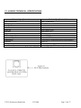
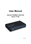
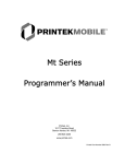
C.1.3 RS232C CONNECTIONS
The RS232C Interface signals for the Extech 3750T are terminated on a 6 PIN RJ25 type data connector located
at the back of the printer.
Six connections are provided from the Serial Interface to the host computer. The table below lists the Serial
Interface signals and pinouts on the RJ25 connector while pin locations are shown in Figure 2.
A minimum of two signal connections are required for operation, RXD - pin3 and Common - pin1.
RJ25 CONNECTOR PIN #
3
2
6
4
1
5
FUNCTIONAL DESCRIPTION
SIGNAL NAME
RS232 from Host
(INPUT)
RS232 from Printer
(OUTPUT)
Request to send from Host (INPUT)
Clear to send from Printer
(OUTPUT)
Logic common
RXD
TXD
RTS
CTS
COM
Table C.1 – Serial Interfaces Signals and pinouts
3750T_Developers_Manual.doc
3/12/2008
Page 33 of 37
C.1.4 RS232C TECHNICAL SPECIFICATIONS
Technical Specification Name
Technical Specification Value
Data Transfer Rate
2400 – 38.4K Baud
Word Length
10 or 11 bits
Start Bit
1
Data Bits
8
Parity Bit
None, Odd or Even
Stop Bits
Auto Select 1 or 2
Signal Levels
RS232C
Mark or Logical 1
-3 to -15 VDC
Space or Logical 0
+ 3 to + 15 VDC
Handshaking
Two modes are supported(Software and Hardware)
Hardware
RTS/CTS
Software
XON/XOFF
Auto Power Up
Positive Signal on RTS input turns printer on
Table C.2. – RS232C – Technical Specifications
Figure 2.0
RJ-25 Data Connector
3750T_Developers_Manual.doc
3/12/2008
Page 34 of 37
C.2.0 Infrared Communications (IrDA)
For IrDA mode to work, Dip Switch #1 must be in the <ON> position. The printer can be powered up by
pressing the power <On/Off> switch. If no IrDA connection is made, the printer will automatically power down
to a lower power level to conserve battery life. It will remain in a “sleep” mode until an IrDA connection is
made, at which time the printer will “wake” up and print the requested data . Pressing the power switch again
will turn the printer <OFF>. The table below shows the required printer settings for IrDA mode. In order for the
printer to be in IrDA mode dip switch # 1 has to be On.
Dip Switch
1
1 and 4
Function
Communication Interface
IrDA Fixed at 9600
Variable IrDA 9600- 38400
Switch #
Switch #
SW1
On
ON
SW 4
OFF
ON
Table C.3 – IrDA Mode
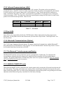
2.1 Direct IrDA
Direct IrDA is also supported by the Extech 3750THS printer. When in that mode the printer surpasses the
IrDA stack . For the printer to be in direct IrDA mode you need to have Dip Switch # 1 and Dip Switch # 6 in
the ON position.
C.3.0 Bluetooth Communications (Option):
The 3750T Printer Supports a Bluetooth Option. The printer control card communicates with the Bluetooth™
base band interface at 38.4K Baud/sec using no parity. To select the Bluetooth™ interface Dip Switch # 3 has to
be ON and all other Dip Switches have to be OFF.
C.3.1 The Bluetooth™ interface power modification
The Bluetooth™ interface increases the battery power consumption by 50 milli Amp. To compensate the
increased power demand, the trickle charge rate is modified to help extend the life of the internal battery
cartridge.. The printer modification is such that the printer can be set to operate in either the MANUAL POWER
OFF or CONTINUOUS ON mode of operation.
C.3.2 MANUAL POWER OFF mode
When demonstrating RF wireless communication, turn the printer on by pressing the ON switch located on the left
side of the printer. The printer will remain active waiting for the wireless print command. Pressing the ON switch
again will turn the printer OFF. For each wireless demonstration, again turn the printer on by pressing the ON switch.
Operation in this fashion will greatly extend the life of the battery cartridge.
3750T_Developers_Manual.doc
3/12/2008
Page 35 of 37
C.3.3 EXTENDED CONTINUOUS ON mode
If it is desired to leave the printer on for extended operation, it would be necessary to switch dip switch #8 to
the OFF position. Be aware that operating with dip switch #8 in this OFF position means that the printer is
always ON thus placing the highest current demand from the battery resulting in reduced battery charge life.
3750T QUICK REFERENCE
ASCII Control Characters:
Character
EOT
BS
HT
LF
VT
FF
CR
SO
SI
XON
AUXON
XOFF
NORM
AUXOFF
CANCEL
ESC
EXTEND
EXTEND OFF
Hex/Dec
04/04
08/08
09/09
0A/10
0B/11
0C/12
0D/13
0E/14
0F/15
11/17
12/18
13/19
14/20
15/21
18/24
1B/27
1C/28
1D/29
CONTROL ACTION
End Of Text
Back Space
Horizontal Tab
Line Feed
Vertical Tab
Form Feed
Carriage Return
Shift Out
Shift In
Transmitter On.
Printer on.
Printer receiver is off
Return to default 42 column mode
Printer to Host: printer is off
Cancel and reset printer BUFFER
Escape
Extended print
Extended print off/Normal print
Table QR1 – ASCII Control Characters
Section
1.1
1.1
1.1
1.1
1.1
1.1
1.1
1.1
1.1
1.1
1.1
1.1
1.1
1.1
1.1
1.1
1.1
1.1
Printer Font Commands – Courier Character Set:
Font Name
Character size (WxH)
Command String
24 CPI normal
8x23
ESC+'k'+'5'
21 CPI normal
9x23
ESC+'k'+'4'
19 CPI normal
10x23
ESC+'k'+'3'
16 CPI normal
12x23
ESC+'k'+'2'
12 CPI normal
16x23
ESC+'k'+'1'
13 CPI rotated
14x16
ESC+'k'+'0'
Table QR 2 – Printer Font Commands – Courier Character Set
3750T_Developers_Manual.doc
3/12/2008
Section
2.1
2.1
2.1
2.1
2.1
2.1
Page 36 of 37
Printer Font Commands:
Command String
ESC – ‘F’ – ‘1’
ESC – ‘F’ – ‘2’
ESC – ‘U’ – ‘1’
ESC – ‘U’ – ‘0’
Printer Action
Section
Selects “International” character set
Selects “PC Line Draw” character set
Enable emphasized print
Disable emphasized print
Table QR3 - Printer Font Commands
A.1.2.
A.1.2.
2.3
2.3
Printer Graphic Commands:
Printer Command String
ESC – ‘A’ – n
ESC – ‘J’ – n
ESC – ‘P’ – ‘#’
ESC – ‘P’ – ‘$’
ESC – ‘V’ – n1 – n2 – <data>
ESC – ‘v’ – n1 – n2 – <data>
Printer Action
Select dot line spacing between printed lines.
Graphic Line Feed command
Select Online mode, characters printed as received
Select Buffer mode, characters are printed on (^D)
8-bit Graphic command
8-bit Compressed Graphic Command
Table QR4 - Printer Graphic Commands
Graphic Logo and Bar code commands:
Command String
ESC – ‘L’ – ‘G’ – n
ESC – ‘G’ – 0x0FF
ESC – ‘L’ – ‘g’ – n
ESC – 'z' – n1 – n2 – L – [data]
ESC – 'Z' – n1 – n2 – L – [data]
ESC – ‘Q’ – ‘J’ – n
ESC – ‘Q’ – ‘Q’ – n
ESC – ‘Q’ – ‘F’ – m
ESC – ‘Q’ – ‘B’ – m
Printer Action
Prepare printer to load image
Loading Logo Complete
Print stored logo image
Print Bar Code without visible text
Print Bar Code with visible text
Reverse Dot Feed
Set Out of Paper Sensitivity
Set Forward Black Mark Seek
Reverse Black Mark Seek
Table QR 5 – Graphic Logo and Bar Code Commands
Section
2.4
2.4
5.5
5.5
3.1
3.2
Section
A.2.2
A.2.2
A.2.2
4.0
4.0
6.2
6.2
6.2
6.2
Printer Supervisory and Control Commands
Command String
^V
^B
ESC – ‘P’ – ‘^’
ESC – ‘P’ – alpa
ESC – ‘M’ – ‘000’ - cr
ESC – ‘M’ – ‘nn0’ - cr
ESC – ‘C’
ESC – ‘P’ – ‘( ‘
ESC – ‘P’ – ‘)’
ESC – ‘P’ – ‘ + ‘
ESC – ‘P’ – ‘ – ‘
Printer Action
Buffer, power timer & battery status
Buffer status
Print Battery Voltage
Time and date print and control
Disable the power down timer
Sets the power down timer to nn seconds
Reset Auto power down to 20 seconds
Firmware version query
Hardware model query
EOT Disable
EOT Enable
Section
5.6
5.6
5.3
5.4
5.4
5.4
5.6
5.6
5.6
5.6
Table QR6 – Printer Supervisory and Control Commands
3750T_Developers_Manual.doc
3/12/2008
Page 37 of 37