1
Mt Series
Programmer’s Manual
Printek, Inc.
1517 Townline Road
Benton Harbor, MI 49022
269-925-3200
www.printek.com
Printek Part Number 5993 Rev B
Acknowledgements
Printek is a registered trademark of Printek, Inc.
Bluetooth is registered trademark of Bluetooth SIG, Inc.
O’Neil is a trademark of O’Neil Product Development, Inc.
Palm OS is a trademark of PalmSource, Inc.
PrintBoy is a registered trademark of Bachmann Software
PrinterCE is a registered trademark of FieldSoftware Products
Wi-Fi is a registered trademark of the Wi-Fi Alliance
Windows is a registered trademark of Microsoft Corporation
All other trademarks are the property of their respective owners.
© 2003, 2004 By Printek, Inc., 1517 Townline Road, Benton Harbor, MI 49022. All rights reserved.
Specifications subject to change without notice.
ii
Table Of Contents
Printer Characters................................................................................................................................................1
Control Characters ............................................................................................................................................1
ASCII Print Characters .....................................................................................................................................2
Extended Print Characters ................................................................................................................................3
Resident Character Sets ....................................................................................................................................4
Flash Based Font Download ................................................................................................................................7
Normal ASCII Font Download.........................................................................................................................7
Extended Font Download .................................................................................................................................8
Graphic Commands ...........................................................................................................................................10
8-Bit Dot Addressable Graphics .....................................................................................................................10
8-Bit Compressed Graphics ............................................................................................................................10
Graphic Logo Commands...............................................................................................................................11
Bar Codes ............................................................................................................................................................13
Code 39 Specifications ...................................................................................................................................13
Code 128 Specifications .................................................................................................................................14
UCC/EAN-128 Specifications ........................................................................................................................15
Interleaved 2 of 5 Specifications.....................................................................................................................16
UPC/EAN/JAN Specifications .......................................................................................................................16
Codabar Specifications ...................................................................................................................................17
Black Mark Sensing ...........................................................................................................................................19
Black Mark Operation ....................................................................................................................................19
Black Mark Printer Commands ......................................................................................................................19
Printer Controls..................................................................................................................................................21
Print Contrast Control.....................................................................................................................................21
Printer Peak-Power Control ............................................................................................................................21
Auto Power Down Feature .............................................................................................................................22
Operating Mode ..............................................................................................................................................22
Printer Status Commands .................................................................................................................................23
Print Battery Voltage ......................................................................................................................................23
Supervisory Commands..................................................................................................................................23
Magnetic Card Reader.......................................................................................................................................25
Card Specifications.........................................................................................................................................25
Magnetic Card Read Command Strings .........................................................................................................25
Magnetic Card Data Output Format ...............................................................................................................26
Magnetic Card Read Error Messages .............................................................................................................26
Interfacing to the Magnetic Card Reader........................................................................................................27
Serial Communications ......................................................................................................................................28
Serial Busy Protocol .......................................................................................................................................28
XON/XOFF Protocol......................................................................................................................................28
RS232C Connections......................................................................................................................................28
iii
Printer Configuration.........................................................................................................................................30
Mt2 Series.......................................................................................................................................................30
Mt3 Series.......................................................................................................................................................31
Mt3-II Series ...................................................................................................................................................32
Command Quick Reference...............................................................................................................................33
Glossary of Terms...............................................................................................................................................37
iv
Printer Characters
For the purposes of software development, there are three types of characters, which may be transmitted to or
from the printer:
Control Characters
• Defined as character encoding {0x00..0x1F}
• Designed to control the printer operation
ASCII Print Characters
• Defined as character encoding {0x20..0x7F}
• Factory default – ISO defined US-ASCII alpha-numeric character set
Extended Print Characters
• Defined as character encoding {0x80..0xFF}
• Factory default – “International” and “PC Line Draw” character sets
Note: ONLY ONE of the Extended Character Sets may be selected per print line
Control Characters
{0x00..0x1F}
The following set of characters is reserved, to assist in printer control. The printer also provides single byte
responses to inform the host of the printer status.
Character
EOT
Control
^D
Hex / Dec
04 / 04
BS
^H
08 / 08
HT
^I
09 / 09
LF
^J
0A / 10
VT
^K
0B / 11
FF
^L
0C / 12
CR
^M
0D / 13
SO
^N
0E / 14
SI
^O
0F / 15
CONTROL ACTION
End Of Text
Printer sends an EOT character when buffer is empty; tells the host
device that printer is in idle mode.
Back Space
Remove previous character in print buffer.
Horizontal Tab
Tab to 5,9,13,17,21,25,29,33,37 or to the beginning of next line.
Line Feed
Advance to beginning of next line.
Vertical Tab
Advance 5 lines.
Form Feed
Advance 10 lines.
Carriage Return
Advance to beginning of next line.
Shift Out
Printer defaults to 24 column mode
Shift In
Printer defaults to 42-column mode.
1
Printer Characters
Character
XON
Control
^Q
Hex / Dec
11 / 17
AUXON
^R
12 / 18
XOFF
^S
13 / 19
NORM
AUXOFF
^T
^U
14 / 20
15 / 21
CANCEL
^X
18 / 24
ESC
^[
1B / 27
EXTEND
^\
1C / 28
EXTEND
OFF
^]
1D / 29
CONTROL ACTION
Transmitter On
Printer to Host: Ready to receive data.
Host to printer: The host is ready to receive data.
Printer on
Printer to Host: Printer is on line. Transmitted after initial power up
or clearing of printer jam or paper reload.
Printer receiver is off
Printer to Host: Print Buffer is full or other error condition.
Host to Printer: host device transmitter off.
Return to default 42 column mode
Printer to Host: printer is off
Transmitted to host before power down or paper out.
Cancel and reset printer
Print buffer is reset and printer placed in initial power-up default
settings.
Escape
Escape character precedes graphics and printer operating modes.
Refer to escape command section.
Extended print
All characters following these commands are printed double high.
Extended print off/Normal print
All characters following this command are printed normal height.
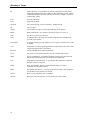
ASCII Print Characters
The printer is delivered with a single factory installed ASCII character set. The factory default is based on the
ISO defined US-ASCII table. The printable characters in the lower half of the character set (0x20-0x7F) are
shown below.
2
Printer Characters
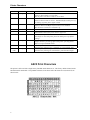
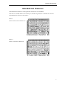
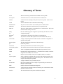
Extended Print Characters
The Extended Print Characters are the upper half of the character set (0x80-0xFF).
There are two extended character sets which may be selected using the ESC F n command. The character
representations for each set are shown below.
ESC F 1
Selects the International character set
ESC F 2
Selects PC Line-draw character set
3
Printer Characters
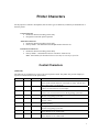
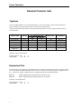
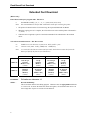
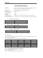
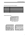
Resident Character Sets
Typefaces
For each resident character set, several font typefaces, or sizes, are available. This provides the character
pitches with the associated columns-per-line as shown in the following table.
A total of four different font tables are used to generate the typefaces. At power up, the default selection is
Courier Mode 2.
FONT NAME
PITCH
Courier Mode 5
Courier Mode 4
Courier Mode 3
Courier Mode 2
Courier Mode 1
Courier Mode 0
(Rotated)
24 CPI
21 CPI
19 CPI
16 CPI
12 CPI
13 CPI
COLUMNS PER LINE
Mt2
Mt3/3-II
48
72
42
63
57
57
32
48
24
36
24 (rows)
32 (rows)
SIZE (WxH)
COMMAND
8x23
9x23
10x23
12x23
16x23
14x16
ESC k 5
ESC k 4
ESC k 3
ESC k 2
ESC k 1
ESC k 0
Example: Select Courier Mode 4
Escape Sequence: ESC
Hexadecimal:
1B
k
6B
4
34
Emphasized Print
For the normal typeface characters, the individual lines or strokes of each character are finer, giving a more airy
feel to the typeface. Emphasized characters have a heavier or thicker line width, putting more emphasis on the
text. A line of text using a resident font may be emphasized using the following command:
ESC U 1
Enable emphasized print starting with the current text line.
ESC U 0
Disable emphasized print starting with the current text line.
Example: Select Emphasized
Escape Sequence: ESC
Hexadecimal:
1B
4
U
55
1
31
Printer Characters
Line Spacing
The line spacing between successive printed text lines may be set using the text line spacing command (ESC a
n). While printing PC Line-draw characters, the line spacing must be set to zero by issuing the ESC a 0
command string, this setting allows connection of graphic characters on successive lines.
During text print, line feeds may be performed at 0.125mm resolution using the graphic linefeed command
(ESC – 'J' – n).
ESC a n
Where n is the number of graphic-line-spacing, in increments of 0.125mm. n = 0…10. The
printer default setting is 3-dot line spacing after each printed text line (n = 3)
ESC J n
Where n is the number of desired 0.125mm graphic line feeds. n = 0…255.
Example 1: Set line spacing to 5 dot lines between character rows.
Escape Sequence: ESC
Hexadecimal:
1B
a
61
5
05
Example 2: Perform 50 graphic line feeds.
Escape Sequence: ESC J
Hexadecimal:
1B 4A
50
32
5
Flash Based Font Download
The Mt2 and Mt3 printers provide the user the ability to replace the factory-installed fonts. This allows the
printer to adapt to many application specific character sets.
Note: To protect the fonts from accidental corruption these must be the first commands received by the
printer when it is powered on.
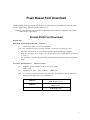
Normal ASCII Font Download
(RS-232 only)
Enter flash ASCII font program mode:
n:
ESC D A n
Reserved for future use (‘0’ is recommended)
Note: This command must be the first ESC command received upon activating the printer.
1.
2.
3.
The printer will deactivate the CTS line and copy the requested Flash bank to SRAM.
When the copying process is complete, the CTS will become active and the printer will transmit a
‘?’ (0x3F).
Any character not accepted, as part of a font load command will be echoed back to the terminal
device.
To Load an ASCII character:
ESC D n1 n2 data
n1:
TABLE to save the character in {0x30, 0x31, 0x32, 0xFF}
(0xFF = quit)
n2:
Character code {0x21 .. 0x7F} {CHR$(33) .. CHR$(127)}
data:
16 x 23 bit (W x H) character matrix (46 bytes total). Each character must also fit into the
matrix specified by the font size (see table below).
TABLE ‘0’
TABLE ‘1’
TABLE ‘2’
Courier Modes 1 & 2
12 & 16 cpi (12 x 23)
Courier Mode 3
19 cpi (10x23)
Courier Modes 4 & 5
21 & 24 cpi (8x23)
7
Flash Based Font Download
Extended Font Download
(RS-232 only)
Enter flash extended font program mode: ESC D X n
n:
Font BANK to modify {‘0’, ‘1’, ‘2’, ‘3’} {0x30, 0x31, 0x32, 0x33}
Note:
This command must be the first ESC command received upon activating the printer.
1.
The printer will deactivate the CTS line and copy the requested Flash bank to SRAM.
2.
When the copying process is complete, the CTS will become active and the printer will transmit a
‘?’ (0x3F).
3.
Characters not recognized, as part of a font load command will be echoed back to the terminal
device.
To Load an extended character: ESC D n1 n2 data
n1:
TABLE to save the character in {0x30, 0x31, 0xFF} (0xFF = quit)
n2:
character code {0x80 .. 0xFF} {CHR$(128) .. CHR$(255)}
data:
16 x 23 bit (W x H) character matrix (46 bytes total). Each character must also fit into the
matrix specified by the font size (see table below).
TABLE ‘0’
TABLE ‘1’
BANK ‘0’
International
12 & 16 cpi
(Courier
Modes 1 & 2)
(12x23)
International
Rotated
(Courier
Mode 0)
(14x23)
BANK ‘1’
International
19 cpi
(Courier
Mode 3)
(10x23)
International
21 & 24 cpi
(Courier
Modes 4 & 5)
(8x23)
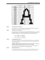
EXAMPLE:
To load a new character ‘A’
STEP 1 –
Describe the Bitmap:
BANK ‘2’
PC Line Draw
12 & 16 cpi
(Courier
Modes 1 & 2)
(12x23)
PC Line Draw
Rotated
(Courier
Modes 0)
(14x23)
BANK ‘3’
PC Line Draw
19 cpi
(Courier
Mode 3)
(10x23)
PC Line Draw
21 & 24 cpi
(Courier
Modes 4 & 5)
(8x23)
This is best done within a font-editing program. Characters must be right justified within the
16 x 23 bit cell. To ensure the characters do not run together, care should be taken to leave at
least a single line of space on one side of each character.
8
Flash Based Font Download
STEP 2 –
Enter flash font program mode:
Using the ESC D A 0 (Hexadecimal 1B 44 41 30) command to program the ASCII (0x20 –
0x7F) character sets. The printer will deactivate the CTS line.
STEP 3 –
Load new character shape for ‘A’:
Once the printer has re-activated the CTS line, and transmitted the character ‘?’, it is possible
to modify the character sets. Transmit the command ESC D 0 A (Hexadecimal 1B 44 30 41)
followed by the data derived from the bitmap as shown. The order of transmission is
Line 1 Left Byte, Line 1 Right Byte,
Line 2 Left Byte, Line 2 Right Byte
…
Line 23 Left Byte, Line 23 Right Byte.
STEP 4 –
Save modified character sets:
Currently all of the character sets are in the printer SRAM and may not be used for printing.
To save the modified character sets into the flash memory, enter the command ESC D -xFF
(Hexadecimal 1B 44 FF).
The printer will transmit the character ‘D’ and then proceed to save the fonts to flash memory.
THE PRINTER POWER MUST REMAIN ACTIVE AT THIS TIME.
Once the fonts have been saved into flash memory, the printer will transmit the character ‘!’.
At this time, the printer will transmit an ‘X’ every 500 milliseconds.
STEP 5 –
Cycle the printer power:
To ensure optimal operation of the printer, remove the battery cartridge from the printer for
several seconds. Replace the battery cartridge and the new fonts will be ready for use.
9
Graphic Commands
8-Bit Dot Addressable Graphics
The printer uses a single line thermal print head with elements spaced at 0.125mm. The Mt2 print head has 384
thermal elements for a total print width of 48mm, and the Mt3 has 576 elements for a print width of 77mm. The
8-bit graphic commands enable control of each one of the heating elements and advancing of the paper by
increments of 0.125 mm.
To select the 8-bit graphic mode the user application must issue the ESC V command. Next, the host
application sends two bytes to indicate the number of the graphic lines desired, followed with packet of 48 bytes
for each graphic line in the Mt2, or 72 bytes for each graphic line in the Mt3 or Mt3-II. The printer prints the
graphic line and advances to the next line automatically.
8-Bit Dot Addressable Graphics commands
ESC V n1 n2 data
n2 n1
data
Example:
16 bit integer indicating the number of graphic lines to be received.
48 bytes of graphic data for the Mt2, or 72 bytes for the Mt3/Mt3-II.
Valid Graphic Character set is from 0x00 to 0xFF Hex using bits 0-7.
ESC V 0x01 0x00 and 72 bytes of data prints a single line of graphics on an Mt3/Mt3-II.
8-Bit Compressed Graphics
ESC v height width counter data counter data…
height
An eight bit value representing the number of dot lines contained in the following data set.
width
An eight bit value representing the number of bytes to be contained in each dot line of the
following data set.
counter
An eight bit value describing how to process the following data:
For signed values counter may be interpreted as follows:
{127 ≥ counter ≥ 0} Process the next (counter + 1) bytes of data as 8 bit graphics.
{0 > counter ≥ -128} Repeat the next single byte of data ((-counter) + 1) times.
For unsigned values counter may be interpreted as follows:
{127 ≥ counter ≥ 0} Process the next (counter + 1) bytes of data as 8 bit +1 times graphics.
{128 ≤ counter ≤ 255} Repeat the next single byte of data, ((256 – counter).
10
Graphic Commands
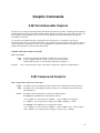
Compressed Graphics Example:
The following graphics data is to be printed:
This data may be represented in hexadecimal:
0x55
0x55
0x55
0x00
0x00
0x55
0x00
0x55
0xAA
0x55
0x11
0x55
The RLE compressed graphics command:
DEC
HEX
ESC
‘v’
height
width
counter
27
1B
118
76
2
02
6
06
255
FF
data…
85
55
255
FF
0
00
3
03
170
AA
17
11
85
55
0
00
253
FD
85
55
Graphic Logo Commands
Storing graphic logos in the printer’s memory will greatly reduce data trasmission time whenever the logo needs
to be printed. The Mt2 and the Mt3-II support up to eight logos, while the Mt3 supports only one.
A utility program is available for Windows desktop systems that will assist in creating the graphic definition of
a logo. This graphic definition provides the graphic commands required in STEP 3, below. The utility.
‘prn2logo.exe’ is provided on the Mt Series Developer’s CD and may also be downloaded from
www.printek.com. Please refer to the documentation provided with the utility for more information.
Mt2 Enter Flash Logo Mode:
ESC D L n
Mt3 Enter Flash Logo Mode:
ESC D L
Mt3-II Enter Flash Logo Mode:
ESC D L n
Load /Record Graphic Logo:
ESC L G n
Stop Loading Graphic Logo:
ESC L G 0xFF
Print Graphic Logo:
ESC L g n
Note:
The Mt2 supports 8 logos. n = 0-7.
The Mt3 supports 1 logo. n = 0.
The Mt3-II supports 8 logos. n = 0-7.
11
Graphic Commands
Graphic Logo Operation
STEP 1 –
Enter Flash Logo Program Mode:
Mt2:
ESC D L n
(Hexadecimal 1B 44 4C and n = 30 – 37).
Mt3:
ESC D L
(Hexadecimal 1B 44 4C)
Mt3-II: ESC D L n
(Hexadecimal 1B 44 4C and n = 30 – 37).
Once received, the printer will deactivate the CTS line.
Note:
STEP 2 –
This command must be the first ESC command received upon activating the printer.
Start Logo Download:
Once the printer has re-activated the CTS line, and transmitted the character ‘?’ it is possible
to start the logo download. The host application selects the Graphic Logo record mode by
sending the load command:
Mt2:
ESC L G n
(Hexadecimal 1B 4C 47 and n = 30 – 37)
Mt3:
ESC L G 0
(Hexadecimal 1B 44 4C 30).
Mt3-II: ESC L G n
Note:
STEP 3 –
(Hexadecimal 1B 44 4C and n = 30 – 37).
Any character not accepted as part of a logo load command will be echoed back to
the host.
Transmit Logo:
While in record mode, the Graphic Logo is downloaded using the 8-bit graphic command:
Mt2:
ESC V n1 n2 48 bytes of graphic data
Mt3:
ESC V n1 n2 72 bytes of graphic data
Mt3-II: ESC V n1 n2 72 bytes of graphic data
STEP 4 –
Save Logo to Flash Memory:
At this time the logo is stored in the printer SRAM and may not be used for printing. To save
the logo into the flash memory, enter the command:
ESC L G 0xFF
(Hexadecimal 1B 4C 47 FF)
The printer will transmit the character ‘D’ and then proceed to save the logo to flash memory.
THE PRINTER POWER MUST REMAIN ACTIVE AT THIS TIME.
Once the logo has been saved into flash memory, the printer will transmit the character ‘!’. At
this time, the printer will transmit an ‘X’ every 500 milliseconds.
STEP 5 –
Cycle the printer power:
To ensure optimal operation of the printer, remove the battery cartridge from the printer for
several seconds. Replace the battery cartridge and the new logo will be ready for use.
12
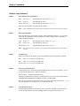
Bar Codes
The Printek Mt2 and Mt3 printers support several bar code symbologies. Two commands are defined for
printing bar codes:
Bar Code Command Formats:
ESC z n1 n2 L data
ESC Z n1 n2 L data
z
Z
n1
print bar code only
prints bar code and ASCII human readable text
bar code type
'1'
Code 39
'2'
Code 128, UCC/EAN-128
'3'
Interleaved 2 of 5
'4'
UPC/EAN/JAN
'5'
Codabar
number of character bytes in data array 1 - 255
height of bar code printed in increments of 0.125mm
n2
L
All barcodes are printed with the minimum bar width (“x-dimension”) of 0.250mm, in compliance with the
respective official specification.
Code 39 Specifications
Description:
Each symbol starts with Leading Quiet Zone, followed with Start Symbol, Data
Symbols, ending with Stop Symbol and Trailing Quiet Zone.
Character set:
36 alphanumeric (0-9, A-Z and '-' 'space' '$' '/' '+' '%')
Note: Only capital letters are supported.
Elements per symbol:
9 (5 bars, 4 spaces)
Character density:
6.25 CPI
Bar width:
0.25mm (narrow to wide ratio of 1:3).
Characters per line:
12 with auto center (maximum).
Example: Print "CODE-39", 1 mm high.
Escape Sequence: ESC
Hexadecimal:
1B
Z
5A
1
31
7
07
8
08
C
43
O
4F
D
44
E
45
2D
3
33
9
39
13
Bar Codes
Code 128 Specifications
Description:
Each symbol starts with Leading Quiet Zone, followed with Start Symbol, Data
Symbols, ending with Stop Symbol and Trailing Quiet Zone.
Character set:
Support for full 256 ASCII set among three subsets.
Elements per symbol:
6 (3 bars, 3 spaces)
Character density:
9.1 CPI
Bar width:
0.25mm
Characters per line:
18 alphanumeric to 36 numeric only (maximum) - automatically centered.
Code 128 Start character:
<start character> {0x87, 0x88, 0x89} determines the character set to be printed.
IF <start character> is 0x87 CODE A:
Characters Sent To Printer
0x020 through 0x03F ASCII
0x040 through 0x07F ASCII
Characters Read By Bar Code Reader
0x020 through 0x03F ASCII
0x00 through 0x07F ASCII
IF <start character> is 0x88 CODE B:
Characters Sent To Printer
0x020 through 0x07F ASCII
Characters Read By Bar Code Reader
0x020 through 0x07F ASCII
IF <start character> is 0x89 CODE C:
Characters Sent To Printer
Characters Read By Bar Code Reader
PAIRS 0x030 through 0x039 ASCII
PAIRS 0x030 through 0x039 ASCII
Note: With CODE C - each number must be paired with another.
Code 128 data Bytes:
The data bytes are defined by which character set is defined. The printer accepts all characters 0x20h - 0x7Fh
with the translations defined above.
Also, characters 0x080 - 0x86 may be used as code 128 control characters:
HEX
0x080
0x081
0x082
0x083
0x084
0x085
0x086
FNC 1:
FNC 2:
FNC 3:
FNC 4:
14
DEC
128
129
130
131
132
133
134
CODE A
FNC 3
FNC 2
SHIFT
change to C
change to B
FNC 4
FNC 1
reserved CODE 128 character (used for UCC/EAN128)
message append (not supported by all bar code readers)
Initialize bar code reader
extend characters (bar code reader reads character + 128)
CODE B
FNC 3
FNC 2
SHIFT
change to C
FNC 4
change to A
FNC 1
CODE C
change to B
change to A
FNC 1
Bar Codes
For example: 'a' is changed from #97 to #97+128 = #225
Note:
It is possible to switch code sets in the middle of the bar code. This is useful with heavily numeric
alphanumeric bar codes (see example below).
Example 1: Print alphanumeric bar code "A2a", 12.5mm high, with human readable text.
n1 = 3 printed characters + 1 start character = 4
L = 12.5mm / 0.125mm = 100
start character = START B (full ASCII alpha numeric) = 0x88
Escape Sequence: ESC Z
Hexadecimal:
1B 5A
2
32
4
04
100
64
STARTB
88
A
41
2
32
a
61
Example 2: Print all-numeric bar code "1234", 5mm high, without human readable text.
n1 = 4 printed characters + 1 start character = 5
L = 5mm / 0.125mm = #40
start character = START C (numeric pairs) = 0x89
Escape Sequence: ESC z
Hexadecimal:
1B 7A
2
32
5
05
40
28
STARTC
89
1
31
2
32
3
33
4
34
Example 3: Print alphanumeric bar code "AB31234", 7mm high, without human readable text.
n1 = 7 printed characters + 1 start character + 1 control character = 9
L = 7mm / 0.125mm = #56
start character = START B (alpha-numeric) = 0x89
Escape Sequence: ESC
Hexadecimal:
1B
z
7A
2
32
0
09
56
38
STARTB
89
A
41
B
42
3 0x83
33
83
1
31
2
32
3
33
4
34
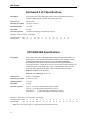
UCC/EAN-128 Specifications
Description:
The UCC/EAN-128 specification is an internationally recognized format for application
identifiers in code 128 bar codes. The bar code symbology is identical to Code 128. These
identifiers are not intended for point-of-sale applications. Only recognized bodies of the
UCC or EAN may assign application identifiers.
More information may be found at www.ean.be for the EAN and/or www.uc-council.org
for the UCC
Example:
Print all-numeric bar code "1234", 5mm high, with human readable text.
n1 = 1 start character + EAN specifier + 4 printed characters = 6
L = 5mm / 0.125mm = #40
start character = START C (numeric pairs) = 0x89
Escape Sequence: ESC Z
Hexadecimal:
1B 5A
2
32
6
06
40 STARTC FNC1 1
28
89
86
31
2
32
3
33
4
34
15
Bar Codes
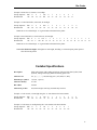
Interleaved 2 of 5 Specifications
Description:
Each symbol starts with Leading Quiet Zone, followed with Start Symbol, Data
Symbols, ending with Stop Symbol and Trailing Quiet Zone.
Character set:
numeric pairs.
Elements per symbol:
10 (5 bars, 5 spaces)
Character density:
11.11 CPI
Bar width:
0.25mm
Characters per line:
24 numeric (maximum), automatically centered.
Example: Print "12345678", 10mm high.
Escape Sequence: ESC
Hexadecimal:
1B
Z
5A
3
33
8
08
80
50
1
31
2
32
3
33
4
34
5
35
6
36
7
37
8
38
UPC/EAN/JAN Specifications
Description:
Each symbol starts with Leading Quiet Zone, followed with Left Guard Bars, Left
Data Symbols, Center Bar Pattern, Right Data Symbols, Check Character, ending
with Right Guard Bars and Trailing Quiet Zone. The UPC, EAN/JAN-8,
EAN/JAN-13 specifications comprise an internationally recognized format for
application identifiers. Unlike the UCC/EAN-128 specification, these identifiers are
intended for point-of-sale applications. Only recognized bodies of the UCC and
EAN may assign application identifiers. More information may be found at:
http://www.ean.be/ for the EAN and
http://www.uc-council.org/ for the UCC
Character set:
numeric - fixed length.
Elements per symbol:
4 (2 bars, 2 spaces)
Character density:
14.5 CPI
Bar width:
0.25mm
Characters per line:
UPC-A: 11 - plus check digit (automatically centered).
UPC-E: 6 - plus check digit (automatically centered).
EAN/JAN-8:
7 - plus check digit (automatically centered).
EAN/JAN-13: 12 - plus check digit (automatically centered).
Example 1: Print UPC-A, 123456123459, 23 mm high.
Escape Sequence: ESC Z
Hexadecimal:
1B 5A
4
34
12 184
0C B8
1
31
2
32
3
33
4
34
5
35
6
36
Note: The received check digit ‘9’ is ignored and recalculated in the printer.
16
1
31
2
32
3
33
4
34
5
35
9
39
Bar Codes
Example 2: Print UPC-E, 0783491, 23 mm high.
Escape Sequence: ESC
Hexadecimal:
1B
Z
5A
4
34
7
07
184
B8
0
30
7
37
8
38
3
33
4
34
9
39
1
31
5
35
4
34
3
33
2
32
1
31
0
30
Example 3: Print EAN/JAN-8, 65432109, 25 mm high.
Escape Sequence: ESC
Hexadecimal:
1B
Z
5A
4
34
8
08
200
C8
6
36
9
39
Note: The received check digit ‘9’ is ignored and recalculated in the printer.
Example: Print EAN/JAN-13, 6543216543219, 20 mm high.
Escape Sequence: ESC Z
Hexadecimal:
1B 5A
4
4
13 160
0D A0
6
36
5
35
4
34
3
33
2
32
1
31
6
36
5
35
4
34
3
33
2
32
1
31
Note: The received check digit ‘9’ is ignored and recalculated in the printer.
Note: UPC/EAN/JAN height: All heights are total height, including a 1.25mm drop bar pattern printed
after the barcode pattern.
Codabar Specifications
Description:
Each symbol starts with Leading Quiet Zone, followed with Start Symbol, Data
Symbols, ending with Stop Symbol and Trailing Quiet Zone.
Character set:
0-9, {$, -, :, /, ., +} and start/stop pairs {A/T, B/M, C/*, D/E}
Elements per symbol:
7 (4 bars, 3 spaces)
Character density:
8.1 CPI
Bar width:
0.25mm
Characters per line:
20 (maximum) plus start/stop, automatically centered.
Example 1: Print 123456, 15 mm high using the ‘A’ start character the host transmits.
Escape Sequence: ESC
Hexadecimal:
1B
Z
5A
5
35
8
08
120
78
A
41
1
31
2
32
3
33
4
34
5
35
6
36
T
54
Example 2: Print 2468, 10 mm high using the C start character the host transmits.
Escape Sequence: ESC
Hexadecimal:
1B
Z
5A
5
35
6
06
80
50
C
43
2
32
4
34
6
36
8
38
*
2A
17
9
39
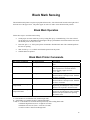
Black Mark Sensing
The Printek thermal printers can print on preprinted form stocks, with a black mark located on the right side of
the front face of the paper stock. The printer paper out sensor is used to sense the black mark position.
Black Mark Operation
Follow these steps to use black mark sensing:
•
Set the paper out sensor sensitivity level by issuing ESC Q Q n command string. The value selected
for the sensitivity is dependant upon the height of the pre-printed black mark located on the form stock.
The default power on value of n is 40.
•
Issue ESC Q F m -or- ESC Q B m printer Command to find the black mark. The command positions
the form for printing.
•
Wait for ESC Q ? ? n1 n2 black mark found response from the printer.
•
Send the data to be printed.
Black Mark Printer Commands
Black Mark Command
Reverse Dot Feed
Command String
ESC Q J n
Out of Paper Sensitivity
ESC Q Q n
Forward Black Mark Seek
ESC Q F m
Reverse Black Mark Seek
ESC Q B m
Printer Black Mark Response:
Paper Found
ESC Q ? ? n1 n2
Printer Black Mark Response:
Paper Not Found
ESC Q 0 0 n1 n2
Description
Perform n reverse dot line feeds, 0.125mm
each.
On paper detect fail, postpone the paper out
error response for n 0.125mm dot lines
before flagging a paper out error.
n = 0…255
Seek black mark using forward feed until m
dot line feeds have been processed. Each dot
line feed = 0.250mm.
Seek black mark using backward feed until m
dot line feeds have been processed. Each dot
line feed = 0.250mm.
n1 and n2 are the high and the low nibble,
respectively, describing how many 0.250mm
dot lines were required to find black mark.
n1 and n2 are the high and the low nibble,
respectively, describing how many 0.250mm
dot lines were processed before reporting
black mark status.
Notes:
n = Total number of 0.125mm dot lines, 0x00 through 0xFF.
m = Total number of 0.250mm dot lines, 0x00 through 0XFF.
n1 and n2 = Total number of 0.125mm dot lines processed, while seeking black mark.
n1 holds the high four bits (0x30 + 4 high bits of count).
n2 holds the low four bits (0x30 + 4 low bits of count).
n1 and n2 can have values 0x30 through 0x3F.
19
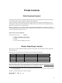
Printer Controls
Print Contrast Control
The contrast of the printed text or graphics depends on the type of the thermal paper used, the printer battery
voltage and the printer contrast setting selected by the host application.
Ten levels of printer contrast settings are supported. This feature insures operation with different grades of
thermal paper available. The printer defaults to the middle contrast. The contrast may be changed by the host
application, using the ESC P n command string.
During the printing process, the battery voltage and the thermal head temperature are monitored. The print
contrast is adjusted to assure consistent printout. The print speed is affected by the contrast setting; fastest print
speed is achieved if the contrast is set to 9.
Print Contrast Control Command
Set the print contrast level:
ESC P n
n = ASCII ‘0’ through ‘9’ {0x30...0x39}
0 = Highest contrast & lowest print speed
5 = Default
9 = Lowest contrast & highest print speed
Printer Peak-Power Control
The peak power control commands enable the operation of the printer with wide range of battery chemistries
and peak capacities.
The printer may be operated in five peak-power modes, as listed in the table below.
Power Mode
1 - Low
2 - Medium
3 - High
4 - Very
5 - Auto
Command
ESC P 1
ESC P 2
ESC P 3
ESC P 6
ESC P 7
Maximum Dots Selected
Heat <64 elements at a time
Heat <128 elements at a time
Heat <192 elements at a time
Heat <576 elements at a time
64, 128, 192, or 576 at a time
Maximum Current
Less than 1.0 Amp
Less than 2.0 Amps
Less than 3.0 Amps
Less than 9.0 Amps
1.5 to 3.0 Amps
The printer default is Auto. While in auto-peak-power mode, the printer counts the number of dots to be fired
and selects the appropriate power mode depending on the available battery capacity. The peak-power setting
directly affects the printing speed; printing is slowest for Low peak-power mode.
Note: The on-board brownout circuit resets the printer controller if peak-power usage exceeds the batteries
power capacity.
Example: Set Printer Peak Power Control to medium.
Escape Sequence: ESC
Hexadecimal:
1B
P
50
2
02
21
Printer Controls
Auto Power Down Feature
In order to conserve battery life the printer features an auto power down timer. The power down timer defaults
to 20 seconds on initial power up.
The auto power down timer may be set or disabled by sending recognized command strings. The auto power
down is re-started on every character received.
The auto power down timer may be disabled by activating the RTS input line, or setting the auto power down
timer to zero, the printer lowers the CTS output line and transmits AUXOFF followed with XOFF before power
down.
Auto Power Down Command
The auto power down command string: ESC M n1 n2 0 CR where n1 or n2 may be '0' to '9'.
Reset Auto power down to 20 seconds: ESC C
Example 1: Set auto power down to occur after 99 seconds.
Escape Sequence: ESC
Hexadecimal:
1b
M
4D
9
39
9
39
0
30
CR
0D
0
30
0
30
CR
0D
Example 2: Disable auto power down.
Escape Sequence: ESC
Hexadecimal:
1B
M
4D
0
30
Example 3: Reset auto power down to twenty seconds.
Escape Sequence: ESC
Hexadecimal:
1B
C
43
Operating Mode
The printer can be operated in two modes, Online or Buffer modes. In online mode, the characters are printed as
they are received. In buffer mode, the characters received are stored in the print buffer and printed upon receipt
of EOT character.
Printer operating mode commands
ESC P #
Select Online mode. Characters are printed as received.
ESC P $
Select Buffer mode. Characters are buffered until receipt of an EOT (0x04).
Example: Select Buffer Mode.
Escape Sequence: ESC
Hexadecimal:
1B
Print Buffered Data:
Control Code:
Hexadecimal:
22
EOT
04
P
50
$
24
Printer Status Commands
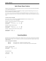
Print Battery Voltage
The battery voltage level may be printed using the following command.
Print Battery Voltage:
ESC P ^
Transmit Battery Voltage: CTRL-V
Example: Print the battery voltage.
Escape Sequence: ESC
Hexadecimal:
1B
P
50
^
5E
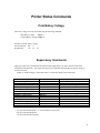
Supervisory Commands
Single byte supervisory commands are designed for host applications to be able to obtain current status
information from the printer. The single byte supervisory commands and serial RS232 response strings are
summarized below.
Note: <4 ASCII hex digits> in the table below are read as hex nibbles OR’ed with 0x30.
Command Description
Print status request:
Print buffer status:
Magnetic card reader status:
Battery status request:
Print buffer status:
Battery Voltage status:
Magnetic card reader status
Firmware version query:
Firmware version:
Example v1.00:
Hardware model query:
Hardware model:
Example:
Status Commands
CTRL-B
Printer Responses
ESC B <4 ASCII hex digits> CRLF
ESC M <4 ASCII hex digits> CRLF
CTRL-V
ESC B <4 ASCII hex digits> CRLF
ESC V <4 ASCII decimal digits> CRLF
ESC M <4 ASCII hex digits> CRLF
ESC P (>
ESC ( <4 ASCII characters> CRLF
ESC ( 1 0 0 SPACE CRLF
ESC P )
ESC ) <4 ASCII characters> CRLF
ESC ) 1 0 3 C CRLF *
* 103 represents the Mt3 printer, ‘C’ is the hardware revision letter.
108 represents the Mt2 printer.
118 represents the Mt3-II printer
23
Magnetic Card Reader
A three track Magnetic Card Reader (MCR) is optionally available on all Printek Mt series model printers. The
MCR is designed to read magnetically encoded data from cards conforming to ANSI/ISO 7810, 7811 standards.
The MCR converts the F2F encoded signals on the magnetic card to ISO7811 compatible ASCII format and
transmit the information to the host computer or a terminal.
The MCR can read one, two, or three tracks simultaneously and bi-directionally.
Set of printer ESC software commands are supported in order to provide the following operating features:
•
Select the MCR.
•
Set the auto time-out software timer
•
Report MCR Read errors
•
Report MCR status.
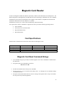
Card Specifications
The table below summarizes the format of the data stored on each magnetic track.
Track Position
Recording Density
Recording Capacity
Number of data bits
Card Thickness
Track 1 - ISO1 (IATA)
210 BPI
79 characters
7
.76 mm +/- 0.08 mm
Track2 - ISO2 (ABA)
75 BPI
40 characters
5
Track3 - ISO3(MINTS)
210 BPI
107 characters
7
Magnetic Card Read Command Strings
•
Six Commands strings are provided, to read the magnetic cards. These commands are summarized in
the table below.
•
The general syntax for commands are as follows:
ESC M n1 n2 t CR
•
The ESC M command turns on the power to the MCR.
•
The next two bytes, n1 n2, are used to set the reader’s timer. ‘01’ through ‘99’ are valid timer settings.
‘00’ disables the timer.
•
The printer aborts and transmits the time-out error message if the operator fails to swipe a card within
the time period set by the host application.
25
Magnetic Card Reader
•
On timeout, the printer aborts the swipe process, transmits timeout error message and turns off the
MCR Indicator.
•
A good magnetic card swipe automatically terminates the read process.
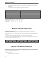
Magnetic Card Command String
ESC M n1 n2 1 CR
ESC M n1 n2 2 CR
ESC M n1 n2 3 CR
ESC M n1 n2 4 CR
ESC M n1 n2 5 CR
ESC M n1 n2 6 CR
ESC C
Description
Read Track1 only
Read Track2 only
Read Track3 only
Read Track1 and Track2 simultaneously
Read Track2 and Track3 simultaneously
Read Tracks 1,2 and 3 simultaneously
Cancel Read process
Example: Read tracks 2 & 3 with a twenty second timeout.
Escape Sequence: ESC
Hexadecimal:
1B
M
4D
2
32
0
30
5
35
CR
0D
Magnetic Card Data Output Format
The track data retrieved from a magnetic card is transmitted to the host in ISO7811 ASCII format as
summarized in the table below.
The first four characters (“%/1/”) flag the track number, the track data follows the flag string, terminated with
? CRLF.
“%;+” are the track start sentinel characters, while “?” is the end of track sentinel character.
If no data is available for a track that data field will be empty. If an Error is encountered on any track a single
“E” will be the output for that tracks’ data field.
%/1/
Track1
Data
?CRLF
;/2/
Track 2
Data
?CRLF
+/3/
Track 3
Data
?CRLF
Magnetic Card Read Error Messages
The characters “%” and “E” preface all error messages. Following these two characters is a comma, the error
number in ASCII (01 through 99), another comma, an English description of the error encountered, and finally
CRLF terminating the Error Message string.
The syntax is as follows:
% E, nn, Error text in ASCII, CRLF
26
Magnetic Card Reader
The printer may transmit Four (4) types of Read Error messages. The following messages terminated with
CRLF are returned.
Error #
05
07
08
09
Error Message Transmitted
Time-out Expired
Invalid Track Number
Unsupported Track Selected
Cancel Request
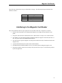
Interfacing to the Magnetic Card Reader
This section details the software steps required to access the MC reader from a computer or a terminal.
•
The host selects the printer by activating the RTS input line or sending wake-up characters to the
printer.
•
The printer sends the XON command to the host to indicate that it is ready to receive data from host.
•
Once XON is received, the host sends the command to enable the magnetic card reader (ESC M 0 0 4
CR). The printer turns on the GREEN MCR Indicator.
•
Once the operator swipes the magnetic card, the printer transmits the track(s) information found on the
magnetic card.
•
A good read automatically turns off the reader and the indicator.
•
The MCR indicator illuminates RED if an error is encountered while reading the magnetic card.
•
The printer transmits a timeout error message if the operator fails to swipe a card in the time period set
by the host application.
27
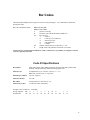
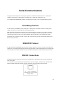
Serial Communications
The proper baud rate and protocol settings are required to communicate with the host device. The printer
defaults to 19200 BAUD, 8 DATA BITS, NO PARIT, and one STOP BIT on initial power up.
Two communication handshaking protocols are supported, Serial Busy protocol and XON/XOFF protocols.
Serial Busy Protocol
For the serial busy handshaking mode, the Request To Send printer input (RTS) and Clear To Send printer
output (CTS) are used to control data flow to and from the printer.
RTS and CTS are considered to be valid or active when the signal level is positive (3 to 12VDC). A positive
RTS signal from the host device enables the printer. The RTS signal is monitored during data transmission
from the printer to the host device, the printer transmits data to the host device only if RTS input is high.
The printer raises CTS when it is ready to accept data. The printer lowers CTS when the print buffer has less
than 256 unused locations.
XON/XOFF Protocol
For the XON/XOFF handshaking mode, the printer transmits XON (0x11) when it is ready to accept data, and
XOFF (0x13) for the print buffer has less than 256 unused locations. Under XON/XOFF protocol, the data flow
out of the printer's serial port is halted on receipt of XOFF from Host device and resumed on receipt of XON.
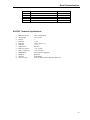
RS232C Connections
The RS232C Interface signals for the printer are terminated on a 6 PIN RJ type data connector located at the
back of the printer.
Six connections are provided from the Serial Interface to the host computer. The table below lists the Serial
Interface signals and pin out on the RJ connector followed by the pin locations on the connector.
28
Serial Communications
PIN #
1, 5
2
3
4
6
FUNCTIONAL DESCRIPTION
SIGNAL NAME
Logic common
COM
RS232 from Printer (OUTPUT)
TXD
RS232 from Host (INPUT)
RXD
Clear to send from Printer (OUTPUT)
CTS
Request to send from Host (INPUT)
RTS
Serial Connector Pin Assignments
RS-232C Technical Specifications
•
•
•
•
•
•
•
•
•
•
•
•
•
Data transfer rate:
Word length:
Start bit
Data Bits
Parity Bit
Stop bits
Signal levels:
Mark or Logical 1:
Space or Logical 0:
Handshaking:
Hardware:
Software:
Auto power up:
2400 - 38.4K Baud
10 or 11 bits
1
7 or 8
None, odd or even
1 or 2
RS232C
-3 to -15VDC
+3 to +15VDC
Two modes are supported
RTS/CTS
XON/XOFF
Positive signal on RTS input turns printer on.
29
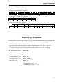
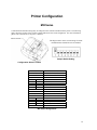
Printer Configuration
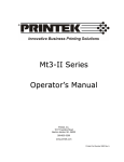
Mt2 Series
Communication and other settings may be changed via the switches located inside the printer. The following
figure shows the location of the switches, and the table shows the switch assignments. For more information,
please refer to the Mt2 Series Operator’s Manual.
The diagram below shows switch settings for IrDA
communications and Auto Power Off enabled.
Sample Switch Setting
Configuration Switch Location
Switch Position(s)
SW1
Off
On
SW2
SW3
Off
Off
Off
On
On
Off
On
On
SW4
Off
On
SW5
SW6
SW7
Off
Off
On
Off
On
On
SW8
Function
Communication Interface
RS232/Bluetooth Enabled
IrDA Enabled
Baud Rate
38,400
19,200
9,600
2,400
Manual Power Control (Mt2B)
Manual Control Disabled
Manual Control Enabled
Reserved
Parity bit
No Parity
Odd Parity
Even Parity
Reserved
Mt2 Switch Assignments
30
Printer Configuration
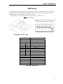
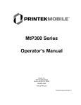
Mt3 Series
Communication and other settings may be changed via the switches located inside the printer. The following
chart explains the various conditions obtained through the various configuration switch settings. For more
information, please refer to the Mt3 Series Operator’s Manual
Note: In order for switch changes to take effect, the printer power must be reset.
The diagram below shows switch settings for IrDA
communications and Auto Power Off enabled.
Example: SW1 Shown in On position
Configuration Switch Location
Switch Position(s)
SW1
Off
On
SW2
SW3
Off
Off
Off
On
On
Off
On
On
SW4
SW5
Off
Off
On
Off
On
On
SW6
On
Off
SW7
SW8
On
Off
Function
Communication Interface
RS232/Bluetooth Enabled
IrDA Enabled
Baud Rate
38,400
19,200
9,600
2,400
Parity bit
No Parity
Odd Parity
Even Parity
Hardware Reset
Enable Reset
Disable Reset (Default)
Reserved
Printer Power Control
Continuous Power On Enabled
Auto Power Off Enabled
Mt3 Switch Assignments
31
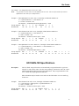
Printer Configuration
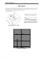
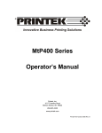
Mt3-II Series
Communication and other settings may be changed via the switches located inside the printer. The following
chart explains the various conditions obtained through the various configuration switch settings. For more
information, please refer to the Mt3-II Series Operator’s Manual
The diagram below shows switch settings for
Bluetooth or Wi-Fi communications.
Switches 2 & 3 Shown In ON Position
Configuration Switch Location
Switch Position(s)
SW1
OFF
ON
SW2
OFF
ON
SW3
OFF
ON
SW4
SW5
OFF
OFF
OFF
ON
ON
OFF
ON
ON
SW6
SW7
OFF
X
ON
OFF
ON
ON
SW8
Function
IrDA Interface
Disabled
Enabled
RS-232C Interface
Enabled
Disabled
Bluetooth/Wi-Fi Interface
Disabled
Enabled
Baud Rate
38,400
19,200
9,600
2,400
Parity
No Parity
Even Parity
Odd Parity
Reserved
Mt3-II Switch Assignments
32
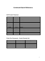
Command Quick Reference
ASCII Control Characters:
Character
EOT
BS
HT
LF
VT
FF
CR
SO
SI
XON
AUXON
XOFF
NORM
AUXOFF
CANCEL
ESC
EXTEND
EXTEND OFF
Hex/Dec
04 / 04
08 / 08
09 / 09
0A / 10
0B / 11
0C / 12
0D / 13
0E / 14
0F / 15
11 / 17
12 / 18
13 / 19
14 / 20
15 / 21
18 / 24
1B / 27
1C / 28
1D / 29
CONTROL ACTION
End Of Text
Back Space
Horizontal Tab
Line Feed
Vertical Tab
Form Feed
Carriage Return
Shift Out
Shift In
Transmitter On.
Printer on.
Printer receiver is off
Return to default 42 column mode
Printer to Host: printer is off
Cancel and reset printer BUFFER
Escape
Extended print
Extended print off/Normal print
Printer Font Commands – Courier Character Set:
Font Name
24 CPI normal
21 CPI normal
19 CPI normal
16 CPI normal
12 CPI normal
13 CPI rotated
MSP Font 10-32 CPI
Character size (WxH)
8x21
9x21
10x21
12x21
16x21
14x16
Dot Matrix Fonts
Command String
ESC k 5
ESC k 4
ESC k 3
ESC k 2
ESC k 1
ESC k 0
ESC F 3 through 8
33
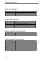
Command Quick Reference
Printer Font Commands:
Command String
ESC F 1
ESC F 2
ESC U 1
ESC U 0
Printer Action
Selects “International” character set
Selects “PC Line Draw” character set
Enable emphasized print
Disable emphasized print
Printer Graphic Commands:
Printer Command String
ESC A n
ESC J n
ESC P #
ESC P $
ESC V n1 n2 data
ESC v n1 n2 data
Printer Action
Select dot line spacing between printed lines.
Graphic Line Feed command
Select Online mode, characters printed as received
Select Buffer mode, characters are printed on (^D)
8-bit Graphic command
8-bit Compressed Graphic Command
Magnetic Card Reader Control Commands
Command String
ESC M nn track CR
ESC C
Printer Action
Enable MCR with nn auto timeout to read track track(s)
Cancel MCR read process
Graphic Logo and Bar code commands:
Command String
ESC L G n
ESC G 0x0FF
ESC L g n
ESC z n1 n2 L data
ESC Z n1 n2 L data
ESC Q J n
ESC Q Q n
ESC Q F m
ESC Q B m
34
Printer Action
Prepare printer to load image
Loading Logo Complete
Print stored logo image
Print Bar Code without visible text
Print Bar Code with visible text
Reverse Dot Feed
Set Out of Paper Sensitivity
Set Forward Black Mark Seek
Reverse Black Mark Seek
Command Quick Reference
Printer Supervisory and Control Commands
Command String
^V
^B
ESC P ^
ESC P alpha
ESC M 0 0 0 CR
ESC M n n 0 CR
ESC M C
ESC P (
ESC P )
Printer Action
Buffer, power timer & battery status
Buffer status
Print Battery Voltage
Time and date print and control
Disable the power down timer
Sets the power down timer to nn seconds
Reset Auto power down to 20 seconds
Firmware version query
Hardware model query
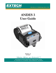
Resident Character Sets:
35
Glossary of Terms
802.11
Wireless networking communication standards created by IEEE.
access point
An interface between a wireless network and a wired network.
Ad-Hoc
A Wi-Fi network consisting of only stations (no access point). Same as Peerto-Peer.
ASCII
American Standard Code for Information Interchange.
authentication
The process a Wi-Fi station uses to identify itself to another station.
bandwidth
The amount of data that be transferred in a given period of time.
baud rate
The rate at which characters are transmitted over a serial interface. This is also
often referred to as bits per second.
binary
Base two numbering system. Digits are represented by the characters 0 and 1.
bit
Bluetooth
A single binary digit.
®
A definition for short range radio frequency communications.
client
Any node on a network that requests services from another node (server).
control code
A single, non-printing character which is used to control the configuration or
operation of the printer.
character pitch
The horizontal spacing of characters. Measured in cpi.
cpi
Characters per inch.
current line
The line upon which the next character will be printed.
current print position
The column on the current line where the next character will be printed.
default
Value or configuration assumed when the printer is powered on or reset.
DHCP
Dynamic Host Configuration Protocol. A method used to centrally control the
assignment of IP addresses on a network.
dpi
Dots per inch. Generally used to refer to graphics density or resolution.
escape sequence
String of characters beginning with the escape (ESC) character which is used
to control the configuration or operation of the printer. The characters which
are part of this string are not printed.
font
A group of characters of a given shape or style.
hexadecimal
Base sixteen numbering system. Digits are represented by the characters 0
through 9 and a through f.
IEEE
Institute of Electrical and Electronic Engineers
infrastructure
A Wi-Fi network consisting of stations connecting to a wired network or other
stations via an access point.
interface
The connection between the printer and the host computer.
37
Glossary of Terms
IP
Internet Protocol. A specification for packets, or datagrams, of data and an
addressing method to allow the exchange of data with another system. Must be
combined with another protocol such as TCP to create a complete connection
with the other system.
LAN
Local Area Network.
LED
Light emitting diode.
line pitch
The vertical spacing of rows of characters. Measured in lpi.
lpi
Lines per inch.
margin
An area along any edge of a form where data may not be printed.
MSB
Most significant bit. In a character, this refers to bit seven (of 0 to 7).
node
Any device connected to a network.
parity
A method used for detecting errors within a single character transmitted or
received via an interface.
Peer-to-Peer
A network consisting of only stations (no access point or central server). Same
as Ad-Hoc.
reset
Initialization of various operating parameters of the printer to the value or state
assumed when the printer is powered on.
RS-232C
An EIA standard for serial data transmission.
server
Any node on a network that provides services to another node (client).
SSID
Service Set IDentifier. An identifier attached to packets on a Wi-Fi network
that identify the particular network the packets are intended for.
TCP
Transmission Control Protocol. A specification that controls the connection
between systems on a network.
WAN
Wide Area Network. Refers to connections that allow one LAN to
communicate with another LAN(s).
WEP
Wired Equivalent Privacy. A security protocol for wireless LANs designed to
provide data security similar a wired LAN.
Wi-Fi®
Refers to any of the IEEE 802.11 standards.
WLAN
Wireless Local Area Network. A LAN made up of wireless nodes.
38