1
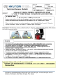
October 8, 2008
TO:
ALL HYUNDAI DEALER PRINCIPALS/GENERAL MANAGERS:
ALL HYUNDAI DEALERSHIP SERVICE MANAGERS:
ALL HYUNDAI DEALERSHIP PARTS MANAGERS:
ALL HYUNDAI DEALERSHIP SALES MANAGERS:
Subject:
Campaign 085 – 2007/2008 Santa Fe and Veracruz Models – Trailer
Hitch Wiring Harness Replacement
Hyundai Motor America is conducting a Customer Notification Trailer Hitch
Wiring Harness Replacement Campaign on certain 2007 and 2008 model year Santa
Fe and Veracruz models equipped with port-installed or dealer-installed
trailer hitches manufactured by Thule Towing Systems.
Thule Towing Systems has identified that ineffective sealing of the converter
module housing may lead to moisture contact with the circuit board, resulting
in corrosion. The corrosion could cause a short circuit and heat related
damage to the wiring harness converter module, which may cause additional
damage to the vehicle. This campaign will provide instructions on completing
the repair and submitting the Campaign claim for reimbursement.
In order to identify only those vehicles affected by Campaign 085, it will be
necessary to access Hyundai Motor America’s “Warranty Vehicle Information”
screen via DCS On-line/WEBDCS before the repair is started. The “Warranty
Vehicle Information” screen will identify affected vehicles with an open
Campaign 085. All in-stock vehicles, if any, must have Campaign 085
completed prior to retailing.
Enclosed with the Service Manager's letter are materials, which were
developed for your use: Dealer Letter, five (5) copies of the Technical
Service Bulletin (TSB# 08-01-015) containing instructions on performing the
service and submitting the campaign claim. TSB #08-01-015 will be
available on Hyundai’s Website on October 8, 2008.
NOTE: This campaign also applies to vehicles that had the previous recall
repair (Campaign 082) made to the Trailer Hitch Wiring Harness.
Customer notification letters will be mailed to all owners of 2007/2008 model
year Santa Fe and Veracruz models on Monday, October 13, 2008.
It is IMPORTANT TO SUBMIT A CAMPAIGN CLAIM FOR EACH VEHICLE SERVICED so your
dealership can be compensated for your work and Hyundai can maintain accurate
records of campaign completions.
LEGAL LIABILITY NOTICE: You are required to keep confidential any and all
information and documents provided to you by Hyundai Motor America in the
conduct of carrying out work for this service campaign. Hyundai Motor
America dealers may use owner information provided for the campaign only for
the purpose of conducting and performing this service campaign, and for no
other purpose.
Hyundai appreciates your cooperation and support. Questions may be directed
to your District Parts and Service Manager or Warranty HELPREP line at 1-877446-2922.
HYUNDAI MOTOR AMERICA
MOTOR VEHICLE RECALL
IMPORTANT NEW RECALL NOTIFICATION!
DO NOT DISCARD!
THIS NOTICE APPLIES TO YOUR VEHICLE EVEN IF YOU HAVE HAD A
PREVIOUS RECALL REPAIR MADE TO YOUR VEHICLE’S TRAILER
HITCH WIRING HARNESS.
Dear 2007 or 2008 Santa Fe or Veracruz Owner:
This notice is sent to you in accordance with the requirements of the National Traffic and Motor
Vehicle Safety Act.
Hyundai has decided that a defect, which relates to motor vehicle safety, exists in certain model year
2007 and 2008 Hyundai Santa Fe and Veracruz vehicles that are equipped with a distributor-installed
or dealer-installed accessory trailer hitch.
This notice applies only to 2007 or 2008 Hyundai Santa Fe or Veracruz vehicles that are equipped with
a distributor-installed or dealer-installed accessory trailer hitch as shown below.
The affected hitch can be identified by the warning label and the distinctive end cap provided.
The part numbers of the affected trailer hitches are:
Part Description
Santa Fe Trailer Hitch
Veracruz Trailer Hitch
Hyundai Part Number
U8610 2B000 and U8610 2B100
U8610 3J000
Federal law requires that any vehicle lessor receiving this recall notice must forward a copy of this
notice to the lessee within ten days.
MOTOR VEHICLE RECALL
What is the problem?
• The trailer hitch wiring harness converter module may experience heat damage even if it has been
previously replaced during a recall repair procedure. Excessive heat may cause damage to the
rear bumper area and may potentially result in a fire.
What will Hyundai do?
• To ensure that your vehicle’s trailer hitch wiring harness converter module does not experience
heat damage, we are asking you to schedule an appointment as soon as possible to take your
vehicle to your Hyundai dealer. The Hyundai dealer will install a newly designed trailer hitch
wiring harness that contains a redesigned circuit board, improved sealing, and a relocated
mounting position. This procedure will be performed at no charge to you.
What should you do?
• We urge you to call your Hyundai dealer to schedule an appointment to have this work
performed as soon as possible. Until your vehicle has been repaired, you should not park your
vehicle in a garage, car port, or other structure.
What if you have other questions?
• If you have any difficulty having this repair performed, we recommend that you call the Hyundai
Customer Assistance Center at 1-800-633-5151. If you are still not satisfied that we have remedied
this situation without charge, and within a reasonable amount of time, you may wish to write to
the Administrator, National Highway Traffic Safety Administration, 1200 New Jersey Avenue, SE,
Washington, D.C. 20590, or call their toll-free Vehicle Safety Hotline at 1-888-327-4236 (TTY: 1-800424-9153), or go to http://www.safercar.gov.
We urge your prompt attention to this important safety matter. Hyundai apologizes for any
inconvenience that this may cause you, however, your safety and the integrity of your vehicle is our
highest concern.
Hyundai Motor America
Technical Service
Bulletin
Group
CAMPAIGN
Number
08-01-015
Date
Subject
TRAILER HARNESS REPLACEMENT PROCEDURE CAMPAIGN 085
CIRCULATE TO:
[X] SERVICE ADVISOR
OCTOBER, 2008
Model
[ ] GENERAL MANAGER [X] PARTS MANAGER
[X] SERVICE MANAGER [X] WARRANTY MGR
2007-2008
VERACRUZ, SANTA FE
[X] TECHNICIAN
[ ] SALES MANAGER
IMPORTANT: DEALERS MUST PERFORM THIS CAMPAIGN ON ALL AFFECTED
VEHICLES PRIOR TO CUSTOMER RETAIL DELIVERY AND
WHENEVER AN AFFECTED VEHICLE IS IN THE SHOP FOR ANY
MAINTENANCE OR REPAIR.
IMPORTANT: WHEN A VEHICLE ARRIVES AT THE SERVICE DEPARTMENT,
ACCESS HYUNDAI MOTOR AMERICA’S “WARRANTY VEHICLE
INFORMATION” SCREEN VIA DCS ON-LINE/WEBDCS TO IDENTIFY
OPEN CAMPAIGNS.
THIS CAMPAIGN MUST ALSO BE PERFORMED ON VEHICLES PREVIOUSLY
REPAIRED UNDER CAMPAIGN 082
DESCRIPTION:
This Bulletin provides a procedure to replace the trailer hitch module and harness.
AFFECTED VEHICLES :
Model: 2007-2008 Santa Fe (CM) and 2007-2008 Veracruz (EN)
Affected vehicle range: Vehicles identified as affected by campaign 085 that are
equipped with previous design trailer hitch control modules. Other vehicles equipped
with a port installed or a dealer installed trailer hitch and previous design trailer hitch
control module, and vehicles equipped with trailer hitch control modules replaced under
Campaign 082.
NOTE: PREVIOUS DESIGN TRAILER HITCH CONTROL MODULES ARE
MOUNTED ON THE REAR BUMPER BEAM. ALL PREVIOUS DESIGN
TRAILER HITCH MODULES, MUST BE REPLACED WITH MODULE THAT
MOUNT UNDER THE VEHICLE.
Page 1 of 33
INDEX
SECTION
VEHICLE SERVICE PROCEDURE
PAGES
1
Santa Fe Trailer Harness with Factory Connectors
5 - 10
2
Santa Fe with ” Direct to Battery” harness
11 - 27
3
Veracruz Factory Connectors-All Vehicles
28 - 33
Page 2 of 33
Technical Service
Bulletin
Group
CAMPAIGN
Number
08-01-015
NOTE: Two (2) types of trailer hitch wiring circuits have been installed on the
2007-2008 Santa Fe. The type of circuit will determine the proper service
procedure. Look inside the driver side rear quarter behind the rear wheel
to determine which procedure is appropriate for each vehicle.
TOOLS REQUIRED
• 10mm Socket
• Ratchet handle
• Wire cutters
• Heat gun
• 14mm Socket
• 10mm end Wrench
• Phillips screw driver
Page 3 of 33
PARTS REQUIRED:
Page 4 of 33
Technical Service
Bulletin
Group
CAMPAIGN
Number
08-01-015
1. SANTA FE TRAILER HARNESS WITH FACTORY CONNECTORS - SERVICE
PROCEDURE
1A. REMOVAL OF THE EXISTING TRAILER HITCH HARNESS
Record all preset radio stations.
Use a 10mm socket to disconnect the
negative terminal on the battery.
CAUTION: Failure to disconnect the
battery may cause damage to
the new replacement trailer
hitch control module.
Carefully disconnect the two trailer hitch
harness connectors located on the driver's
side, behind the rear wheel next to the
muffler.
After disconnecting the trailer harness, push
the grommet, factory wires and connectors
through the grommet hole.
IMPORTANT: If no connector is present,
skip to the Direct to Battery
Service Procedure #2 on
page 11.
Remove all anchors with a flat head screw
driver by prying from behind the anchors.
Page 5 of 33
Remove the harness from the trailer hitch.
Remove the trailer hitch control module and
harness by grasping the module by the hand
and gently rotating it back and forth until the
adhesive separates from the bumper
reinforcement.
NOTE: Removed modules/harnesses
MUST be returned to the WTC. Do
not damage the module. Do not
cut the attached wire harness.
1B. INSTALLATION OF NEW TRAILER HITCH HARNESS
Open rear hatch. Remove the rear bumper
facia by removing all screws.
- 5 Phillips head screws on each side of
wheel well.
- 3 expansion fasteners below each side of
bumper
- Remove Phillips head screws near the
rear tail light on each side.
- Remove 4 bolts underneath the bumper
between the 2 mufflers.
NOTE: Starting from the wheel well,
carefully pull bumper facia away
from vehicle and store to prevent
paint damage.
Page 6 of 33
Technical Service
Bulletin
Group
CAMPAIGN
Number
08-01-015
On left (driver's) rear side of vehicle, remove
the Pressure Relief Vent (PRV) by lifting up
the top flap and use fingers to unhook the
locking tabs on the top of the vent.
CAUTION: Take care not to damage the
PRV locking tabs.
Locate the grommet beneath the lower body
panels near the left (driver's) side muffler.
Route factory trailer hitch harness
connectors into the hole by inserting the
connectors into the hole.
Before placing the new control module in the
new location, connect the 2 connectors
previously pushed through the grommet hole
inside the PRV cavity to the module inlet
connectors.
Clean inner flat surface of 'D' pillar as shown
in the picture with provided alcohol pad.
Page 7 of 33
NOTE: DO NOT REMOVE tie wrap around
the module and adhesive.
Peel the adhesive paper backing off the
module. With the grommet side down, firmly
press the module in place.
Route the trailer module connector with the
reflective coating through the previous
grommet hole and out underneath the
vehicle.
Assure the seal of the grommet to the sheet
metal hole.
Route a fish wire down from the tail light
access panel inside the left rear (driver's)
side interior trim panel. Follow the existing
vehicle wiring next to the side curtain airbag
cylinder and down into the pressure relief
vent opening.
Attach the trailer harness fuse holder to the
fish wire and carefully pull the fuse holder
into the tail light access panel while guiding
with fingers up from the bottom.
Secure the trailer harness fuse holder to the
existing vehicle wiring using a provided
cable tie.
CAUTION: DO NOT secure fuse holder to
yellow air bag wire harness.
Page 8 of 33
Technical Service
Bulletin
Group
CAMPAIGN
Number
08-01-015
Route the 4 wire connector with the reflective
coating rearward toward the left rear
(driver's) side muffler hanger, staying above
the lower bumper bracket bolt.
Clean surface with provided alcohol pads
then apply the 2 anchors onto the location as
shown in the picture.
Using a heat gun, apply heat to each anchor
point for 1 minute to cure the adhesive.
Route harness above the muffler hanger.
Secure the foam bumper backing onto the
composite bumper reinforcement structure
with a small piece of tape on each side to
hold in position.
Clean surface above the bumper
reinforcement bar. Apply the anchors and
cure the adhesive with the heat gun as
previously stated.
Replace Pressure Relief Vent. Ensure the
flaps hang down.
Replace rear bumper facia by securing with
all the screws. First align bumper facia by the
body panel just below the tail lights.
Page 9 of 33
Continue routing the trailer wiring harness 4
pin connector down the bumper support
bracket.
Clean the bumper support bracket with
provided alcohol wipe.
Apply the anchors and cure the adhesive
with the heat gun as previously stated.
Remove the dust cover and carefully push
the 4 pin connector through the connector
mounting bracket from under the vehicle
until it snaps in place.
Cover the plug with the dust cover.
Reconnect the negative battery cable.
Reset all recorded radio stations.
Check the 4 wire connector per the flow
chart in the installation instructions for
correct operation.
WARRANTY INFORMATION:
OP CODE
OPERATION
OP TIME
Hitch02
Sante Fe Replace Controller
Harness-Factory Connector
1.0
NOTE: Submit claim using the campaign claim screen.
Page 10 of 33
Technical Service
Bulletin
Group
CAMPAIGN
Number
08-01-015
2. SANTA FE WITH “DIRECT TO BATTERY” HARNESS - SERVICE PROCEDURE
2A. Removal Of Existing Trailer Hitch Harness
Record all preset radio stations.
Use a 10mm socket to disconnect the
negative terminal on the battery.
CAUTION: Failure to disconnect the
battery may cause damage to
the new replacement trailer
hitch control module.
Raise rear hatch door and remove the wiring
harness access cover from the interior trim
panel located on the left of the vehicle.
Using a 10mm socket, remove the 3
fasteners securing the tail light to the vehicle.
Carefully pull the tail light away from the
vehicle and do not allow the tail light to hang.
Repeat for right side of vehicle.
Cut Yellow, Brown, Blue w/Black stripe wires
2 inches away from wire taps on the left tail
light. (Shown in Photo)
Cut the Green wire 2 inches away from the
wire taps on the right tail light. (Not shown)
Remove old trailer harness from vehicle.
Page 11 of 33
Seal the original vehicle harness by placing
one of the short heat shrink tubes over the
end of each of the cut wires. ( total of 4 heat
shrink tubes)
Pinch tube ends and heat the shrink tube
with a heat gun to seal the tube to the wire.
Repeat for all wires cut. (Brown, Yellow,
Blue w/ Black stripe on the left and Green on
the right.)
NOTE: The end of the shrink tube
extending past the end of the wire
must seal flat to keep moisture out.
Remove black ground wire ring terminal
from the muffler heat shield.
Reminder: Make sure that the battery
cable has been disconnected prior to
cutting red wire.
Cut red wire near heat wrap as shown.
Page 12 of 33
Technical Service
Bulletin
Group
CAMPAIGN
Number
08-01-015
Remove the trailer hitch control module and
attached harness that is placed inside the
bumper structure by gently rotating back and
forth until the adhesive breaks away.
Remove all the anchors by prying off with a
flat head screw driver.
NOTE: Removed modules/harnesses
MUST be returned to the WTC. Do
not damage the module. Do not
cut the attached wire harness.
Completely clean and remove all remaining
adhesive tape from the top of the rear
bumper reinforcement.
Remove all the wire ties securing the red 12
gauge power wire to the underside of the
vehicle.
From the position near the vehicle battery,
carefully disconnect the trailer module's red
12 gauge wire and remove from the vehicle.
Page 13 of 33
2B. INSTALLATION OF NEW TRAILER HITCH HARNESS
Remove the rear bumper facia by removing
all screws.
-5 Phillips head screws on each side of
wheel well.
Remove the lower expansion fastener (push
pin) securing the wheel well liner to the
bumper cover. The same fastener is used to
hold mud guard in place (if installed).
-3 expansion fasteners below each side of
bumper
-Remove Phillips head screws near the rear tail light on each side.
-Remove 4 bolts, using a 10 mm socket,
underneath the bumper between the 2
mufflers.
NOTE: Starting from the wheel well,
carefully pull bumper facia away
from vehicle and store to prevent
paint damage.
On left (driver's) rear side of vehicle, remove
the Pressure Relief Vent (PRV) by lifting up
the top flap and use fingers to unhook the
locking tabs on the top of the vent.
CAUTION: Take care not to damage the
PRV locking tabs.
Page 14 of 33
Technical Service
Bulletin
Group
CAMPAIGN
Number
08-01-015
Install new control module by connecting the
2 connectors inside the cavity.
Clean inner flat surface as shown in the
picture with provided alcohol pad.
Peel the adhesive backing off the module.
With the grommet side down firmly press the
module in place.
NOTE: Revised control module has a tie
around the module and adhesive
backing.
Locate the blind grommet beneath the lower
body panel near the left (drivers) side
muffler. Remove and discard blind grommet
Page 15 of 33
Route the trailer control module connector
with the reflective coating through the
grommet hole in the pressure relief opening
and out underneath the vehicle.
Assure the seal of the grommet to the sheet
metal hole.
Route the 4 wire connector with the
reflective coating rearward toward the left
(driver's) side muffler hanger, staying above
the lower bumper bracket bolt.
Clean surface with provided alcohol pads
then apply the anchors onto the location as
shown in the picture.
Apply the anchors and cure the adhesive
with the heat gun as previously stated.
Page 16 of 33
Technical Service
Bulletin
Group
CAMPAIGN
Number
08-01-015
Using a fish wire tool, route the Brown,
Yellow and Blue w/Black stripe wires from
the grommet under the body, up behind the
bumper and out into the left tail light opening
as illustrated.
Apply 2 anchors in the location as shown.
Prior to applying the anchors, clean the
surface with provided alcohol pads.
Apply the anchors and cure the adhesive
with the heat gun as previously stated.
Secure the wire harness to the anchors with
supplied wire ties.
Anchor orientation as shown in the picture.
Route the harness containing the Green wire
across the top of the bumper reinforcement
to the right side tail light.
Use the alcohol pads to clean the surface in
3 positions as indicated in the picture. Allow
the surface to dry before proceeding.
Remove the protective tape from 3 of the
anchor points and mount in the cleaned area.
Apply the anchors and cure the adhesive
with the heat gun as previously stated.
Secure the wire harness to the 3 anchors
with wire ties.
Anchor orientation as shown in the picture
Page 17 of 33
Using the fish wire tool, route the Green wire
up and out into the right taillight opening.
Apply 2 anchors in the location as shown.
Prior to applying the anchors, clean the
surface with provided alcohol pads.
Apply the anchors and cure the adhesive
with the heat gun as previously stated.
Secure the wire harness to the anchors with
supplied wire ties . Anchor orientation as
shown in the picture.
Attach the trailer hitch wiring harness to the
rear light wiring cut in the prior steps. Splice
the trailer hitch harness wires as listed in the
chart below, using the grease filled wire taps
provided.
WARNING: Using non grease filled connectors could lead to possible corrosion
and light/harness malfunction.
Page 18 of 33
Technical Service
Bulletin
Group
CAMPAIGN
Number
08-01-015
To properly secure the wire tap, open the
cover completely and lay the original wire
completely into the exposed channel. Insert
the trailer harness module wire into the
opening up to the stop. With both wires
properly positioned inside the wire tap, use a
pair of blunt nose pliers to seat the blade and
pierce each wire in the wire tap. With the
blade secured, close the cover of the wire
tap, allowing it to lock in place.
NOTE: Failure to properly secure the wire
tap may lead to intermittent
operation of the harness and
potential electrical system damage.
Position the wires within both tail light
openings to avoid cutting or pinching the
wires when the tail light assembly is secured.
Using a 10 mm socket reinstall the 3
fasteners securing both the tail lights to the
vehicle.
NOTE: Below is an overview of the Wire Path Installation - Module to Battery
Page 19 of 33
Remove the driver's side rear wheel.
Remove the inner wheel plastic liner by
removing the seven flanged plastic nuts
using a 14 mm socket and ratchet.
Remove one plastic pin above the brake
line. Wire Path Location A.
NOTE: Refer to the overview of the Wire
Path Installation.
Use the red wire with coverings to route to
fuse box in engine area. Route through
wheel well as shown. Wire Path
Installation Location A.
Using the alcohol wipe provided, clean the
flat surface above the ABS brake sensor
wire, allow the surface to dry before
proceeding.
Remove the protective tape from the anchor
point and mount in the cleaned area as
illustrated.
Using a heat gun, apply heat to the anchor
point to cure the adhesive.
Secure the wire harness to the anchor point
using the provided cable tie. Wire Path
Installation Location A.
Page 20 of 33
Technical Service
Bulletin
Group
CAMPAIGN
Number
08-01-015
Secure the Black ground wire to shielded
wire harness using the provided cable tie as
illustrated.
Using a 10 mm wrench remove the front left
nut securing the heat shield above the left
muffler.
Position the ring terminal on the black
module wire on the exposed stud and
replace the nut. Wire Path Installation
Location A.
Route the harness above the exposed fuel
pipe mounting bracket located just above the
shock absorber mount bolt. Wire Path
Installation Location A.
Continue routing the harness between the
Emergency Brake cable and above the large
fuel filler pipe. Wire Path Installation
Location B.
NOTE: Refer to the overview of the Wire
Path Installation.
Page 21 of 33
Secure the harness to the lower brake line
using the provided cable tie. Locate tie in
front of the brake line support bracket as
shown. Wire Path Installation Location B
indicated in photo.
Route harness above the fuel pump plastic
cover and secure using the provided cable
tie to the lower brake line at corner of the
pump cover. Wire Path Installation
Location C indicated in photo.
NOTE: Note: Refer to the overview of the
Wire Path Installation.
Continue to route the harness on the inside
of the frame rail and secure to brake line
using a provided cable tie just behind the
bracket supporting the brake and fuel lines
as illustrated. Wire Path Installation
Location C indicated in photo.
Route the harness along the brake line and
secure using provided cable tie to the
bracket supporting the brake and fuel lines.
Wire Path Installation Location D
indicated in photo.
Page 22 of 33
Technical Service
Bulletin
Group
CAMPAIGN
Number
08-01-015
Continue to route the harness between the
engine sub frame and under the frame rail,
and secure with provided cable tie to lower
brake line beside the sway bar. Wire Path
Installation Location D indicated in photo.
Route harness upwards along the brake line
into engine compartment and secure with
provided cable tie at the brake line bracket
as illustrated. Wire Path Installation
Location D indicated in photo.
CAUTION: Make sure the harness does
NOT contact or interfere with
the steering column boot.
At the front of the vehicle with the in-line15
amp fuse REMOVED, attach the ring
terminal on the end of the Red 12 gauge
power wire to the inboard stud in the power
distribution center using a 10 mm socket.
Tighten securely to ensure a proper
connection. Replace the fuse box cover.
Wire Path in Engine Compartment
indicated in photo.
CAUTION: Failure to properly tighten this
fastener may result in
intermittent operation and or
damage to the vehicle's
electrical system and or the
trailer wiring harness.
Page 23 of 33
Secure the harness fuse holder cover
bracket to the wire harness in front of the
battery using the provided cable tie as
illustrated. Wire Path in Engine
Compartment shown in photo.
Route the harness through the two air filter
securing clips as illustrated. Wire Path in
Engine Compartment shown in photo.
Bundle up the excess wire and secure to the
brake line using provided cable tie as
illustrated. Wire Path in Engine
Compartment shown in photo.
Reinstall the wheel liner with the seven
plastic flange nuts using a 14 mm socket
and ratchet and install the plastic push pin.
Replace the left rear wheel assembly.
Torque the lug nuts to 89-108 Nm, (9-11
Kgf-m, 65-79 lb-ft).
Page 24 of 33
Technical Service
Bulletin
Group
CAMPAIGN
Number
08-01-015
Replace the Pressure Relief Vent cover to its
proper position, ensuring that the rubber
flaps are pointing down.
Reseat the foam bumper backing onto the
composite bumper reinforcement structure,
using a small piece of tape on each end of
the foam to hold in position during
reassembly.
Align the bumper cover to the rear of the
vehicle and carefully press into place.
Adjust the bumper cover left and right,
aligning with the body panel just below the
tail lights. (driver side shown)
Replace the two shoulder screws (one per
side) securing the bumper cover to the rear
body near the tail lights.
Page 25 of 33
Replace the four bolts securing the bumper
brackets to the bumper cover.
Replace the five Phillips head screws
securing the bumper cover to the wheel
openings on each side of the vehicle.
NOTE: If equipped, install the mud
guards during this step, using the
bottom two screws. An additional
fastener is located below the mud
guard, inserted vertically.
Replace the six (three per side) expansion
fasteners, securing the bumper cover to the
lower body panels near the mud guards.
Continue routing the trailer wiring harness
4-pin connector across the top of the
bumper reinforcement and down along the
bumper support bracket.
Clean the bumper support in the illustrated
positions with a provided alcohol wipe. Pull
the backing from the last two cable anchors
and mount to the bumper support as
illustrated.
Page 26 of 33
Technical Service
Bulletin
Group
CAMPAIGN
Number
08-01-015
Apply the anchors and cure the adhesive
with the heat gun as previously stated.
Secure the wire to the bumper support
bracket with a supplied cable tie as illustrated.
Once the trailer hitch has been installed,
remove the dust cover and carefully push the
4 pin connector through the connector
mounting bracket from under the vehicle until
it snaps in place.
NOTE: Note: Attach the dust cover from
the 4- pin connector after
mounting the connector to the
bracket.
Using a 10 mm socket, attach the (-) battery
cable to its original position on the negative
(-) battery post.
Insert the 15 Amp fuse in the in-line fuse
holder on the harness red power wire near
the battery.
Reset all recorded radio stations.
Check the 4 wire connector per the flow chart
in the installation instructions for correct
operation.
WARRANTY INFORMATION:
OP Code
HitchT03
Operation
Santa Fe Replace Controller Harness- Direct To Battery
Op Time
1.4 hr.
NOTE: Submit claim using the campaign claim screen
Page 27 of 33
3. VERACRUZ FACTORY CONNECTORS SERVICE PROCEDURE - ALL
VEHICLES
3A. REMOVAL OF EXISTING TRAILER HITCH HARNESS
Record all preset radio stations.
Use a 10mm socket to disconnect the
negative terminal on the battery.
CAUTION: Failure to disconnect the
battery may cause damage to
the new replacement trailer
hitch control module.
Disconnect the 2 connectors on the trailer
hitch wiring harness located on the right
(passenger) side, behind the rear wheel next
to the muffler. At this location, push the
grommet and connectors through the hole in
the inside body panel.
Remove the underbody trailer hitch wiring
harness and all anchors with a flat head
screw driver by prying from behind the
anchors.
Page 28 of 33
Technical Service
Bulletin
Group
CAMPAIGN
Number
08-01-015
Remove the trailer hitch control module and
harness by grasping the module by hand and
gently rotating it back and forth until the
adhesive separates from the bumper
reinforcement.
NOTE: Removed modules/harnesses
MUST be returned to the WTC. Do
not damage the module. Do not
cut the attached wire harness.
3B. INSTALLATION OF NEW TRAILER HITCH HARNESS
Open the tool tray and temporarily remove
the jack assembly and foam liner out of the
tray.
With cargo door open, remove the tool tray
by unscrewing the 3 screws securing the
tray. One screw on left side, one in the
middle, one under the jack assembly foam
liner.
Use a trim tool and pry up the sill panel to
remove.
Page 29 of 33
Remove Phillips head screw securing the
lower corner of the side interior panel on the
passenger side near the sill plate.
Pull panel apart by using this cargo anchor.
Reach into opening and locate the vehicle
harness connectors.
Route the trailer hitch module's 4 pin
connector out the bottom of the vehicle
through the grommet hole. Push the
grommet located on the 4 pin connector
harness all the way through the hole.
Page 30 of 33
Technical Service
Bulletin
Group
CAMPAIGN
Number
08-01-015
Connect the new trailer hitch module's
connectors to the vehicle tow hitch
connectors. Press connectors firmly together
until the locking tabs engage. Use the
provided alcohol wipes to clean the flat
surface as shown, before applying the
module into its location. Remove the tape
backing and stick to surface.
New Location
From underneath the vehicle, seat the
grommet found on the 4 pin connector
harness into the opening. Confirm that the
grommet seals to body.
Route the 4 pin trailer connector harness
rearward toward the right (passenger) side
muffler hanger, staying above the lower
bracket bolt.
Clean the area behind each of the anchor
points on the connector harness with the
alcohol wipes provided.
Carefully remove the paper backing from
each anchor point and secure to the cleaned
area.
Using a heat gun, apply heat to each anchor
point for 1 minute to cure the adhesive.
Page 31 of 33
Continue routing the 4 pin connector trailer
wiring harness across the top of the bumper
reinforcement and down along the bumper
support bracket.
Clean the area behind each of the anchor
points with the provided alcohol wipes and
cure adhesive with heat gun as previously
stated.
Secure the cable to the bumper support
bracket using a supplied wire tie.
Remove the dust cover and carefully push
the 4 pin connector through the connector
mounting bracket from under the vehicle
until it snaps in place.
Secure the fuse holder to the existing
vehicle wiring using a cable tie to allow it to
be accessed from underneath the tool tray.
Page 32 of 33
Technical Service
Bulletin
Group
CAMPAIGN
Number
08-01-015
Return the right side interior trim to its
original position. Replace the Phillips head
screw to the lower corner of the trim panel.
Press the sill panel firmly into its original
position. Use a trim panel tool to ensure the
weather seal is not pinched under the sill
panel.
Return the tool tray to its original position by
securing with the 3 Phillips head screws
inside the tray. Replace the foam liner and
the jack assembly.
Reconnect the negative battery cable with a
10 mm socket.
Reset all recorded radio stations.
Check the 4 pin connector per the flow chart
in the installation instructions for correct
operation.
WARRANTY INFORMATION
OP
Code
Operation
OP Time
HitchT01
Veracruz - Replace Controller Harness
0.9 hr.
HitchT02
Santa Fe - Replace Controller Harness
See page 10
HitchT03
Santa Fe - Replace Controller Harness
See page 27
NOTE: Submit claim using the campaign claim screen
Page 33 of 33