1
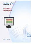
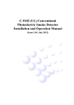
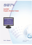
GST-FT8WN Fire Telephone Panel Installation and Operation Manual GST-FT8WN Fire Telephone Panel The Intelligent Solution CONTENTS 1 GENERAL......................................................................................................................................1 2 TECHNICAL SPECIFICATIONS ...............................................................................................1 3 PANEL INSTRUCTION................................................................................................................2 4 5 3.1 APPEARANCE AND STRUCTURE.................................................................................................2 3.2 THE FRONT SURFACE.................................................................................................................3 3.3 THE KEYS .................................................................................................................................3 3.4 INDICATORS ..............................................................................................................................3 3.5 DIGITRON DISPLAY ...................................................................................................................4 FIRE TELEPHONE SYSTEM DESIGN.....................................................................................4 4.1 STAND ALONE FIRE TELEPHONE SYSTEM .................................................................................4 4.2 NETWORKED FIRE TELEPHONE SYSTEM ...................................................................................5 MOUNTING & COMMISSION...................................................................................................5 5.1 INITIAL CHECK .........................................................................................................................5 5.2 WIRING REQUIREMENT.............................................................................................................5 5.3 MOUNTING HOLES ....................................................................................................................6 5.4 TERMINALS ON THE PANEL........................................................................................................6 5.5 SYSTEM COMMISSIONING .........................................................................................................7 Set panel address..........................................................................................................................7 Register the Network Panels .......................................................................................................7 Test Functions................................................................................................................................7 6 7 USER GUIDE .................................................................................................................................8 6.1 CALL HANDSET ........................................................................................................................8 6.2 CALL TELEPHONE PANEL ..........................................................................................................8 6.3 CALL TELEPHONE PANELS IN NETWORK ...................................................................................8 6.4 PANEL TO PANEL .......................................................................................................................8 TROUBLESHOOTING ................................................................................................................9 7.1 ZONE FAULT .............................................................................................................................9 7.2 NETWORK FAULT ......................................................................................................................9 Page II GST-FT8WN Fire Telephone Panel The Intelligent Solution 1 General GST-FT8WN fire telephone panel is specialized for emergency communication, builds up convenient and prompt 2-way communication in case of fire and other abnormal conditions. It is an indispensable device in fire protection system. The panel has features as below: Easy wall mount installation 24VDC power supply Receiving and calling out with fire telephone handsets Networkable fire telephone panels achieve internal communication Call from handset will be transferred to networked fire telephone panels automatically after not answered by the dedicated panel The handset zones are fully monitored for fault of short circuit and open circuit. Panel will show the fault by sound and indicator. Failure of one zone will not effect on other zones The network communication is monitored. When sub-panel fails to communicate with the main panel, the main panel will get the failure message and broadcast to other networked sub-panels, both main panel and sub-panels will indicate by sound and light indication. When the fault happens on main panel, all sub-panels will show the fault message, and meanwhile the network call will be inhibited. 2 Technical Specifications Operation Voltage 24VDC±10% Standby Current 0.15A Maximum Current 0.75A Frequency Range 300~3400Hz Crosstalk <-60dB Transmission Loss <5dB Environment Temperature -5~40°C Relative Humidity 45%~95% Dimension 400mm × 280mm × 100mm Gross Weight 4.15kg Network Capacity 8 panels Panel Capacity 8 zones Zone Capacity 5 handsets End of Line Resistor 10kΩ±0.5KΩ Page 1 GST-FT8WN Fire Telephone Panel The Intelligent Solution Notes: words using within this file Fire Telephone Panel (Panel): Installed in fire control center, the device can communicate with field terminals, such as GST-FT8WN. Handset: Field device, which can communicate with fire control center, such as P-9911(F) and P-9911(M). Main panel: The No.1 panel in the fire telephone panel network Sub-panel: Panels other than No.1 in the fire telephone panel network 3 Panel Instruction 3.1 Appearance and Structure GST-FT8WN fire telephone panel is wall mount type, the appearance is shown in Fig.3-1 Fig.3-1 Page 2 GST-FT8WN Fire Telephone Panel 3.2 The Intelligent Solution The front surface Fig. 3-2 3.3 The Keys Key Description “Mute” Stop the alarm sound caused by fault “Network Call” Answer or start network call Zone 1-8 Answer, call or hang up the corresponding zone. 3.4 Indicators Indicator “Call” LED, 1-8 “Ring In” LED “Fault” LED, 1-8 “Network Fault” LED Description Red, indicating the conversation status between panel and corresponding zone. ¾ Flashing: in the process of connection ¾ On: under conversation ¾ Off: no conversation Red, fast flash when there is call in from network or zone Yellow, lit on when corresponding zone in Fault condition Yellow, lit on when there is network fault Page 3 GST-FT8WN Fire Telephone Panel The Intelligent Solution “Power” LED Green, lit based on usual power supply “Mute” Red, lit when panel sound alarm silenced “Rev” Green, lit when panel receiving network data “Trans” Red, lit when panel sending network data “Rev” and “Trans” LED located at the back of the door 3.5 Digitron Display State Example Description Network Free On the main panel, the first digit indicates the quantity of panels in the network, the last digit indicates its network address On sub-panel, only the last digit will show its network address Network Call The first digit indicates the address of the calling panel. The C at the last digit means Calling. Network Conversation The sample at the left shows the conversation state between No.1 panel and No.2 panel. The others will show “BUSY” The first digit indicates the address of failed panel. The E means Error. Network Failure 4 Fire Telephone System Design 4.1 Stand Alone Fire Telephone System Fig. 4-1 shows a standalone fire telephone system. The panel can connect maximum 8 zones with each zone maximum 5 handsets. Fig. 4-1 Page 4 GST-FT8WN Fire Telephone Panel 4.2 The Intelligent Solution Networked Fire Telephone System The system consists of a group of panels as many as 8. The panel with the address 1 is the main panel and the rests are sub-panels. Please refer to commission section for setting up addresses. Fig. 4-2 5 Mounting & Commission 5.1 Initial Check Check the appearance of the panel after open the box. Then power on and check working state. 5.2 ¾ ¾ ¾ ¾ Wiring Requirement Cross-section area of the power cable not less than 1.5mm2 Twisted-pair cable connecting panel and handset with SA not less than 1.0 mm2 Twisted-pair cable for the network with SA not less than 1.0 mm2 The cable selection must comply with local code Page 5 GST-FT8WN Fire Telephone Panel The Intelligent Solution Note: the impedance of single line not more than 20Ω 5.3 Mounting Holes Fig. 5-1 Fig. 5-1 shows the mounting holes of the panel ¾ Hole distance in the vertical direction 318mm ¾ Hole distance in the horizontal direction 218 mm ¾ Diameter of the hole 12mm 5.4 Terminals on the panel Fig. 5-2 Power (+24, GND): 24VDC power in, polarized E: GND Network (+, -): Network, polarized Zn+, Zn-: Zone Terminals, connecting with handsets (a 10KΩ±0.5KΩ resistor is required to the last point of each zone). Page 6 GST-FT8WN Fire Telephone Panel 5.5 The Intelligent Solution System Commissioning Please Make Sure the Correct Wiring before Commissioning. Set panel address ¾ ¾ ¾ For standalone fire telephone system, the address can be assigned 1 or keep the default setting There must be one panel assigned 1 in the network fire telephone system Opening the door of the panel, the red PIN switch in the left corner is using for panel address setting. The addresses’ range is from 1 to 8. Please refer to Fig. 5-3. Fig. 5-3 Note: The panel addresses can not be repeated in same network. Register the Network Panels After assigning the addresses, power on the sub-panels first. Press and hold the “Network Call” button on the main panel and power on. The main panel will register all networked sub-panels automatically. Subsequently, the first digit of the digitron will show the number of networked panels (including the main panel). Check whether all panels have been registered according to the shown number. If no consistency, check the wiring and repeat the above-mentioned process. The registration information is saved in non-volatile memory, will not loss on power off. The registration should be carried out again in case adding or removing network panels. Not necessary for registration on sub-panel. Test Functions Test the other functions according to Operation Manual after commissioning. Page 7 GST-FT8WN Fire Telephone Panel The Intelligent Solution 6 User Guide 6.1 Panel Call Handset Press a key of zone 1 to 8, the corresponded zone will be called with “Call” LED slow-flashing. The conversation will be set when handset picked-up, with “Call” LED lit showing status. During the conversation, press the key again will stop the call. The “call” LED won’t go out until hanging up the handset. If the handset is hung up first, the conversation will stop immediately with “Call” goes out. The panel can make call to handsets in other zones when a conversation is underway. 6.2 Handset Call Panel Once the handset is picked up without being called, the call will go to the panel. The panel will ring with “Call” and “Ring In” LED fast-flashing. Press the relative key and enter into conversation with “Call” being on, “Ring In” goes out. Meanwhile, if there are other zones calling panel, “Ring In” will keep fast-flashing. Hang-up the handset or press the relative key on the panel will stop the conversation. 6.3 Call Panels in Network If the handset call is not answered by the panel within 12s, and the network is available, the call will be transferred to other networked panels. Press “Network Call” and start the conversation. Stop the conversation by handset hanging up or “Network Call” repressed. 6.4 Panel to Panel Call When network is available, press “Network Call” will send the call to entire network with the LED indicator fast-flashing. Meanwhile, the digitron on other networked panels will show by flashing “X — —C” (X- The calling panel), the “Ring In” and “Network Call” LED will fast flash with ringing sound. Press “Network Call” button and then start the conversation. The digitron of the panels not attending conversation will show “BUSY” and the ring tone stops. Panel in conversation will show the address of the other one. Either part can stop the conversation by pressing “Network Call”. Page 8 GST-FT8WN Fire Telephone Panel The Intelligent Solution 7 Troubleshooting 7.1 Zone Fault The zone fault shows an open or short circuit between panel and handsets, or the End of Line Resistor not connected. Check the cable by multi-meter, whether the resistance is roughly 10kΩ. 7.2 Network Fault The panel shows network fault when there is any of the panels powered off or network cable fault. Check the malfunction panel and wiring. Page 9 GST China Gulf Security Technology Co., Ltd. No. 80, Changjiang East Road, QETDZ, Qinhuangdao, Hebei, P. R. China 066004 Tel: +86 (0) 335 8502528 Fax: +86 (0) 335 8508942 Email: [email protected] www.gst.com.cn GST UK Global System Technology PLC Lion Court, Staunton Harold Hall, Melbourne Road, Ashby de la Zouch, Leicestershire, England LE65 1RT Tel: +44 1283 225 478 Fax: +44 1283 220 690 Email: [email protected] www.gst.uk.com GST Dubai Global System Technology PLC PO Box 17998 Unit ZA04 JEBEL ALI Free Zone, Dubai, UAE Tel: +971 (0) 4 8833050 Fax: +971 (0) 4 8833053 Email: [email protected] www.gst.uk.com