1
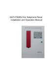
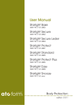
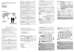
C-9102 (UL) Conventional
Photoelectric Smoke Detector
Installation and Operation Manual
(Issue 1.04, July 2012)
C-9102 (UL)
Conventional Photoelectric Smoke Detector
Installation and Operation Manual
CONTENTS
I
II
III
IV
V
VI
VII
VIII
IX
X
General ................................................................................................................ 1
Features ............................................................................................................... 1
Technical Specifications ....................................................................................... 1
Structure and Operation Principle ........................................................................ 2
Mounting and Wiring ............................................................................................ 2
Testing .................................................................................................................. 4
Troubleshooting ................................................................................................... 5
Maintenance ......................................................................................................... 6
Cautions ............................................................................................................... 6
Quality Warranty .................................................................................................. 7
C-9102 (UL)
Conventional Photoelectric Smoke Detector
Installation and Operation Manual
I
General
C-9102 (UL) Conventional Photoelectric Smoke Detector (hereinafter called the
detector) is a non-addressable detector, applicable to hotels, restaurants, office
buildings, teaching buildings, banks, warehouses, libraries, computer rooms and switch
rooms, etc. It can be connected with compatible fire alarm control panel (FACP) through
a 4.7kΩ terminal resistor to detect fire.
II Features
The detector adopts the latest scattering technology and excellent photoelectric
components, improving the reliability, stability and conformity of the sensor. With
special optical sensing chamber, it has high ability of insect-proof, dust-proof, and
interference-proof of external rays. With novel structure and attractive appearance, the
detector has stable and reliable performance and high damp-proof ability.
III Technical Specifications
1.
2.
Operating Voltage: 12VDC~28VDC
Operating Current:
Standby Current:≤60μA
Alarm Current: 10mA≤I≤30mA
(Note: The alarm current depends on the current limit of the FACP. It’s not
allowed to power the detector directly by 24VDC. Otherwise the detector will
be blown as a result of without current limiting resistor.)
3.
4.
5.
6.
7.
Alarm Reset: Instantaneous Cut-out (5s MAX, 2.5VDC MAX)
Initiating Time:≤10s
Sensitivity:1.23%/ft~2.02%/ft
Maximum Ripple Voltage: 4V(peak-to-peak value)
Alarm Confirming LED: Red, not lit when in normal operation, constantly lit when
alarming.
Monitoring Area: When space height is 6m~12m, the monitoring area of a detector
is 80m 2 for normal protection area; When space height is less than 6m, it is 60 m 2.
Wiring: Connecting with the power cable by polarized two-wire.
Operating Environment:
Temperature:
0℃~37.8℃ (UL268)
Relative Humidity:≤95%, non-condensing
Dimension: Diameter: 100mm Height: 42mm (without base)
Diameter: 105mm Height: 56mm (with base)
Ingress Protection: IP22
Material and Color of Enclosure: ABS, ivory white
Weight: About 120g
Matching Parts: DZ-03 Base
Standard Applied: UL268
8.
9.
10.
11.
12.
13.
14.
15.
16.
Page 1
C-9102 (UL)
Conventional Photoelectric Smoke Detector
Installation and Operation Manual
IV Structure and Operation Principle
1.
Appearance of the detector is shown in Fig. 1.
Fig. 1 Appearance
2. Operation Principle
The detector detects fire by scattering of infrared beam, whose circuit is consisted of
infrared beam emitting part and receiving part. The emitting diode and photodiode are
in the optical sensing chamber, which can screen interference of outside light without
preventing entrance of smoke particles. In smokeless condition, it only receives very
weak infrared light; When smoke particles enter, the received light signal increases by
scattering; When smoke reaches certain density, it can output alarm signal. To reduce
interference and power consumption, the emitting circuit works intermittently in order to
increase the life of emitting diode.
Alarm output signal works on current mode, for series connection of several detectors
and checking of fault and fire.
V Mounting and Wiring
Warning: Before installing the detector, disconnect the power from the loop and
verify that all bases are securely installed and that the wiring polarity is correct at
each base.
1. Mounting of the detector is shown in Fig. 2.
Page 2
C-9102 (UL)
Conventional Photoelectric Smoke Detector
Installation and Operation Manual
Wiring Tube
上盖
防尘罩
Embedded Box
防虫网
迷宫
Orientation Base
螺钉
Detector
探测器底部
2.
Fig. 2 Mounting
Bottom and base of the detector is shown in Fig. 3 and Fig. 4.
Record Label
A
B
DZ-03
C
Mounting Hole
Fig. 3 Bottom of the detector
Fig. 4 Orientation base
3. Wiring Method
The base of the detector is DZ-03 Base produced by GST. The bottom of the detector
and the orientation base are shown in Fig. 3 and 4. There are four terminals with
numbers on the base, “1” connects with the anode of the output end of compatible FACP,
“2” connects with terminal No. “1” of the next base as output, “3” connects with terminal
No. “3” of the next base and the cathode of the output end of compatible FACP, “4”
doesn’t connect to any wires but is used to fix the detector accessorily. A 4.7k/1w
terminal resistor can be connected between terminal “2” and “3” of the last base in a
loop. System connection is shown in Fig. 5.
Page 3
C-9102 (UL)
Conventional Photoelectric Smoke Detector
Installation and Operation Manual
Output+
4.7k
Terminal
Resistor
Compatible
FACP
Output-
DZ-03 Base
DZ-03 Base
CAUTION: DO NOT USE LOOPED WIRE UNDER TERMINAL 3. BREAK WIRE
RUN TO PROVIDE SUPERVISION OF CONNECTIONS.
Fig. 5 Wiring
4. Mounting
There are location elements on the detector and the orientation base to ensure there is
only one installing position. There are two marks on point A and B of the orientation
base, and a mark on point C of the side face of bottom of the detector. When installing,
aligning the mark C of the detector to point A of the orientation base, rotate the detector
clockwise to point B, then the detector is installed.
The detector base is designed with anti-tamper function. After installing the detector
onto the base, twist a ST2.9X6.5 cross recessed pan head tapping screw into the hole
on the side of the base to prevent removal of the detector. Then the detector can only
be removed after twisting off the screw by a screwdriver. (Note: Please use this function
only when necessary to avoid trouble in maintenance and repair.)
5. Location and Spacing
1) The horizontal distance from the detector to the wall or the girder should not be
less than 0.5m.
2) There should not be any obstruction within 0.5m around the detector.
3) The horizontal distance from the detector to the blast hole of any
air-conditioner should not be less than 1.5m; that to the multi-hole ceiling blast
should not be less than 0.5m.
4) When installing detectors on corridor ceilings not wider than 3m, they should
be placed in the middle. The spacing should not be more than 15m. The
distance from the detector to end wall should not be more than half of the
spacing.
5) The detector should be installed horizontally. If it has to be installed aslant, the
gradient angle should not be more than 45o.
6. Wiring: 227 IEC 06 cable with cross section not less than 1.0mm 2.
VI Testing
Warning: Power up only after all devices are well connected.
1.
2.
3.
Before testing, notify the proper authorities that the system is undergoing
maintenance and will temporarily be out of service. Disable the zone or system
undergoing maintenance to avoid unwanted alarms.
Test the detector after installation and regular maintenance.
Test Method
Page 4
C-9102 (UL)
Conventional Photoelectric Smoke Detector
Installation and Operation Manual
1) Field testing can be done by Trut300 Smoke Detector Sensitivity Tester of No Climb
Products Ltd. (for detailed description, please refer to Trutest Smoke Detector
Sensitivity Tester User Manual Issue2.1c) or similar smoke generating tools. If
Trut300 is used, adjust its obscuration to 1.7% /ft to 2.6% /ft according to the
manual, start testing until the detector alarms. If the tester shows “pass”, the
detector passes the test.
2) You can also use similar smoke generating tools (cigarette or smoke gun) and blow
the smoke at the smoke-in hole (Fig. 6) into the detector until it alarms.
Note: This test is only used for verifying the ability of the detector to alarm after smoke
enters. It cannot be used to test its sensitivity.
LED
Smoke in
Recess
4.
5.
Fig. 6 Testing
After testing, reset the detector by power-cut over 5s. Notify the proper authorities
the system is back in operation.
If a detector fails in testing, clean it as described in "Maintenance" and test again. If
it still fails, please return it for repair.
VII Troubleshooting
In case of any fault, check connecting cables and fixing screws first, then open the
housing to see if there is loose soldering or blown parts.
Possible trouble and solution during operation are as follows:
1. No alarm:
Check whether the detector is securely installed on the base. There should be DC24V
voltage on terminals No. 1 and 3 of the base, if not, check the cable with the FACP open
or not.
2. Nuisance alarm:
Check the LED on the detector lit or not. If not, check the polarity of wiring and whether
there are short circuits on terminating resistor. If it's lit, check whether the chamber in
the detector is too dirty and needs to be cleaned. Otherwise, the circuit may be broken.
Page 5
C-9102 (UL)
Conventional Photoelectric Smoke Detector
Installation and Operation Manual
VIII Maintenance
1.
2.
3.
The detector should be cleaned at least once a year to ensure normal operation of
the system.
Before cleaning, notify the proper authorities that the system is undergoing
maintenance and will temporarily be out of service. Disable the zone or system
undergoing maintenance to avoid unwanted alarms.
Remove the detector to be cleaned. Take down the top cover by prizing along the
three recesses with a minus screwdriver and clean the dust on the insect net by a
vacuum pump or cleaner; if there is too much dust or it cannot be totally cleaned,
you can take down the sensing chamber and pull out the insect net along axle,
clean or replace the insect net, then remove the dust on the sensing chamber by
vacuum pump or cleaner, and re-install the insect net and sensing chamber (note to
install them to the end). Align the orientation marks on the two parts of enclosure
and re-install the top cover. See Fig. 7.
Orientation Mark
Sensing Chamber
Insect Net
4.
Fig. 7 Cleaning
Test the detector again after re-installation.
IX Cautions
1.
2.
The dust cover cannot be removed until the project has been put into usage. It
should be well kept for future use.
Dust covers are an effective way to limit the entry of dust into smoke detector
sensing chambers. However, they may not completely prevent airborne dust
particles from entering the detector. Therefore, we recommend the removal of
Page 6
C-9102 (UL)
Conventional Photoelectric Smoke Detector
Installation and Operation Manual
detectors before beginning construction or other dust producing activity. Be sure to
notify the proper authority for the removal of the detectors.
3. In maintenance, note to be careful to avoid damage to the detector.
4. The detector may not sense fire that starts where smoke cannot reach it such as in
chimneys, in walls, on roof, or on the other side of closed doors.
5. The detector cannot detect fire beyond its monitoring area.
6. The detector may not alarm in time for fire caused by inadequate fire protection
measures, explosion, gas leakage, arson and children playing with fire.
7. In high velocity environment, the alarm may be delayed by dilution of smoke
density due to frequent and fast air exchange.
8. The detector has a limited life. To ensure the detector is always in good operation
state, please maintain it according manufacturer’s recommendations and relative
national code.
9. The detector should be tested regularly, at least once a year.
X Quality Warranty
This detector is approved by UL as a recognized component. It’s strongly
recommended that fire alarm control panel manufacturers intending to use this detector
in their fire alarm systems to verify system compatibility before application in order to
avoid system failure.
Gulf Security Technology Co., Ltd. warrants that the detector will be free from
defects in design, materials and workmanship. The warranty is valid for a period of 2
years from time of dispatch. This warranty shall not apply to any product that is found
to have been improperly installed or used in any way not in accordance with the
instructions supplied with the product. Anybody, including the agents, distributors or
employees, is not in the position to amend the contents of this warranty. Products not
covered by this warranty shall also be returned for repair. Please return the products
together with a description of fault and possible reason to No.80 Changjiang East Road,
QETDZ, Qinhuangdao, Hebei, P.R. China, Gulf Security Technology Co., Ltd. Postcode:
066004.
Page 7
Gulf Security Technology Co., Ltd.
No. 80, Changjiang East Road, QETDZ, Qinhuangdao, Hebei,
P. R. China 066004
Tel: +86 (0) 335 8502434
Fax: +86 (0) 335 8502532
[email protected]
www.gst.com.cn
30302468