1
SPP
8-ZONE SYSTEM PRECISION PANEL
VIA!NET
EXT IR
TO SENSE INPUTS
1
2
SS/SC4
3
USE STEREO 3.5mm PLUGS ONLY
4
5
6
ZONE
ZONE
1
5
TRIGGERS
1
2
3
4
5
6
7
8
ZONE
2
ZONE
POWER
ZONE
3
ZONE
+
6
ZONE
--
16VDC / 10A
4
7
ZONE
8
16VDC / 4A
16VDC/1.5A
ELAN
HOME
SYSTEMS
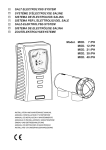
SPP
INSTALLATION MANUAL
Contents
Introduction ............................................................................................................................. 2
Features ............................................................................................................................... 2
SPP Front/Rear Panel ........................................................................................................ 3
System Design ........................................................................................................................ 4
Pre-Wire ............................................................................................................................... 4
SPP System Wire Runs ...................................................................................................... 6
Rough-In ............................................................................................................................... 6
Trim-Out ............................................................................................................................... 7
Connections
Rear Connections .......................................................................................................... 8
RJ-45 Pin Out ................................................................................................................... 8
SPP Punch-Down Connectors ...................................................................................... 8
VIA!®Touch Panel Connections ..................................................................................... 9
Via! Touch Panel “A” Connections ....................................................................................... 9
Via! Touch Panel “B” Connection ....................................................................................... 10
INT 12V-EXT 16V Switch .................................................................................................. 10
Olé Film Interactive Touchpads .................................................................................. 10
Olé “A” Punchdown Locations-16V ................................................................................... 11
Olé “B” Punchdown Locations-16V .................................................................................... 11
Olé “B” Punchdown Locations-12V ................................................................................... 12
Olé “C” Punchdown Locations-12V ................................................................................... 12
Z•Pad Connections ....................................................................................................... 13
Keypad “C” Punchdown Locations-S8 ............................................................................... 13
Keypad “C” Punchdown Locations S6/S12 ......................................................................... 13
ZNET/VNET Switch ........................................................................................................ 14
External Power Connections ....................................................................................... 14
IR Receiver Connections ............................................................................................. 15
External IR Input (EXT IR IN) Connections ................................................................ 15
PVSE Precision Panel ................................................................................................... 16
SPP to VSE100/VSE2 (No PVSE Precision Panel) ................................................... 17
Sense Trigger Inputs .................................................................................................... 17
Front Connections ....................................................................................................... 18
VIA!NET Connection ...................................................................................................... 18
Zone Keypad Inputs ..................................................................................................... 18
SS/SC4 Connection ...................................................................................................... 19
VIA!®Power Connections ............................................................................................... 20
Trigger Connections ..................................................................................................... 20
Sense Input Connections ............................................................................................. 21
EXT IR Connections .......................................................................................................21
Multi-Chassis Connections ..................................................................................... 22
Quick Reference Guide ................................................................................................... 23
Front Panel Connections ............................................................................................. 23
Rear Panel Connections .............................................................................................. 24
Appendix: Rear Overlays .............................................................................................. 25
Warranty .................................................................................................................. Back Page
© ELAN Home Systems 2007 • All rights reserved.
Page 1
SPP
ELAN
INSTALLATION MANUAL
HOME
SYSTEMS
Introduction
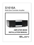
The SPP System Precision Panel is designed to simplify the installation of ELAN S Series Multi-Room Controllers
and provide a reliable, logical connectivity solution. Designed to work with ALL S Series models (S6, S8.6AV,
S8.6AVP, and S12), the SPP has provisions for each connection type required for a complete multi-room system
installation: from a simple six zone S6 scenario to a complex thirty-two zone S12 automation showcase.
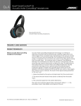
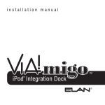
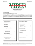
Features
The rear panel of the SPP features a neatly laid out array of all the 110 punch-downs necessary to ensure the
quick, reliable connection of keypads, touchpads and touch panels in every zone. The INT 12V-EXT 16V switches
(one per zone) selects between internally generated voltage of the System Controller (+12 Volts DC) or externally generated voltage from a 16 VDC power supply connected to the front of the SPP. There are also dedicated
punch-down connectors for six ELAN™Sense sensors, eight Triggers, and EXT IR signals.
Two custom Overlays are included that show both the color-code and functions of every connection of the
System6, System8 and System12. There are RJ-45 jacks and a switch on the rear of the panel for an easy link to
an additional SPP, SC-4 System Controller or SS1 System Station.
A ZNET/VNET switch selects between systems based on ZNET (S6 and S12 multi-room controllers) and VNET
(S8).
Use ELAN C4545 one or two meter RJ-45-to-RJ-45 interconnect cables for reliable connections every time. Six
Sense Input jacks use stereo 3.5mm interconnect cables to go directly to the Sense Inputs. Eight Zone Trigger
Output jacks use mono 3.5mm interconnect cables to go directly to the Trigger Outputs. A mono 3.5mm EXT IR
connector is available for use with the S12 and SS1 System Station. The front panel also features DC power jacks
for 1 Amp, 4 Amp, and 10 Amp VIA! power supplies for easy connection.
The front panel of the SPP is removable, making all rear-panel punch-downs easy. PBKT6P new construction
rough-in brackets are available, or the SPP can easily be retro-fitted using the four clamping legs attached to the
frame, which clamp the panel securely to drywall. Additional panels are required for systems with two, three or
four S8 or S12 chassis.
NOTE: Multiple System6 chassis cannot be combined in one system.
Each punch-down location can contain two wires; one on top of the other. Use the included 110 punch-down tool
to make connections to the rear panel of the SPP. Make sure to use the included punch-down caps so that connections do not inadvertantly become loose!
VIA!NET
EXT IR
TO SENSE INPUTS
1
2
SS/SC4
3
USE STEREO 3.5mm PLUGS ONLY
4
5
6
1
2
3
4
5
6
7
8
ZONE
ZONE
1
5
TRIGGERS
ZONE
2
ZONE
POWER
ZONE
3
ZONE
+
6
ZONE
--
16VDC / 10A
4
7
ZONE
8
16VDC / 4A
ELAN Precision Panels save
time and make sense out
of complex wiring jobs!
16VDC/1.5A
Page 2
© ELAN Home Systems 2007 • All rights reserved.
ELAN
HOME
SPP
SYSTEMS
INSTALLATION MANUAL
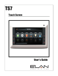
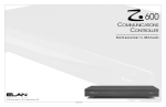
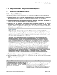
SPP Front/Rear Panel
Front Panel
VIA!NET
}
1
2
7
6
EXT IR
TO SENSE INPUTS
1
SS/SC4
2
}
3
USE STEREO 3.5mm PLUGS ONLY
4
6
5
ZONE
ZONE
1
5
TRIGGERS
1
2
3
4
5
6
7
8
ZONE
ZONE
2
6
POWER
ZONE
ZONE
ZONE
--
+
3
7
ZONE
16VDC / 10A
4
8
16VDC / 4A
16VDC/1.5A
1
VIA!NET RJ-45 Port
2
Zone 1-8 RJ-45 Ports
3
3.5mm Mono Triggers Connections
4
16 VDC Power Connections for PWR1,
5
PWR4, PWR10 Power Supplies
2
5
SS1/SC4 RJ-45 Port
6
3.5mm Stereo Sense Input Connections
7
3.5mm Mono EXT IR Connection
®
3
4
10
9
8
7
6
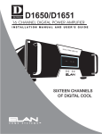
Rear Panel
LINK IN
LINK OUT
N/C
IR
485485+
G
16V
G
16V
1
V+ G
2
V+ G
3
V+ G
485485+
G INT
V
G
V
EXT
4
V+ G
N/C
IR
N/C
IR
485-
485-
485+
485+
G
12V
G
N/C
G
16V
G
16V
N/C
IR
N/C
IR
485-
485-
485+
485+
G
12V
G
N/C
G
16V
G
16V
5
485485+
G
INT V
G
V
EXT
N/C
IR
485485+
6
V+ G nc
INT G
V
G
V
EXT
nc V+ G
RED+
3
Z1B 16V/12V VIA!/OLÉ
7
V+ G
8
V+ G
Z1C 12V OLÉ/ZPAD
Z2C 12V OLÉ/ZPAD
Z1A 16V VIA!/OLÉ
485485+
G
INT V
G
V
EXT
N/C
IR
N/C
IR
485485+
N/C
12V
G
N/C
1
N/C
IR
Z3C 12V OLÉ/ZPAD
G
16V
G
16V
N/C
12V
G
N/C
Z2B 16V/12V VIA!/OLÉ
485485+
N/C
IR
485485+
Z3B 16V/12V VIA!/OLÉ
G
V INT
G
V
EXT
N/C
IR
N/C
IR
Z2A 16V VIA!/OLÉ
Z5C 12V OLÉ/ZPAD
485485+
NO SS/SC4
G
INT V
G
V
EXT
N/C
IR
485485+
N/C
12V
G
N/C
N/C
IR
485485+
N/C
12V
G
N/C
9
V+ G
BLACK-
Zones Punchdown Blocks
2
External Power Connectors
3
RS485 Expansion Block
4
SS/SC4 Switch
5
External IR Punchdown Block
6
3.5mm Stereo Sense Input Connections
7
Triggers Punchdown Blocks
8
Link Out RJ-45 Connection
9
Z-NET/V-Net Switch
10
Link In RJ-45 Connection
5
Z4C 12V OLÉ/ZPAD
Z8B 16V/12V VIA!/OLÉ
G
16V
G
16V
G
16V
G
16V
SS/SC4
N/C
IR
485485+
Z4B 16V/12V VIA!/OLÉ
485485+
485485+
G
G
V INT 12V
G
G
V
N/C
EXT
N/C
IR
485+
Z3A 16V VIA!/OLÉ
N/C
IR
485485+
N/C
12V
G
N/C
485-
Z4A 16V VIA!/OLÉ
Z7B 16V/12V VIA!/OLÉ
G
16V
G
16V
N/C
IR
S8.6/S12.8
(VNET)
485+
EXT IR
IR
G
IR
G
IR
G
IR
G
ZONES 1/2/3/4
N/C
IR
485-
T1
G
T2
G
T3
G
T4
G
TRIGGERS 1/2/3/4
S6/S12
(ZNET)
Z6C 12V OLÉ/ZPAD
485485+
G
V INT
G
V
EXT
N/C
N/C
IR
IR
Z7C 12V OLÉ/ZPAD
Z6A 16V VIA!/OLÉ
N/C
IR
485+
Z8C 12V OLÉ/ZPAD
Z6B 16V/12V VIA!/OLÉ
G
16V
G
16V
N/C
IR
485-
T5
G
T6
G
T7
G
T8
G
SENSE 2 SENSE 1
SENSE 4 SENSE 3
SENSE 6 SENSE 5
485+
Z8A 16V VIA!/OLÉ
2
Z5B 16V/12V VIA!/OLÉ
Z5A 16V VIA!/OLÉ
}
S
G
V
G
S
G
V
G
ZONES 5/6/7/8
N/C
IR
485-
Z7A 16V VIA!/OLÉ
1
S
G
V
G
S
G
V
G
TRIGGERS 5/6/7/8
TRIGGERS
SENSE INPUTS
S
G
V
G
S
G
V
G
1
10
V+ G
2
4
© ELAN Home Systems 2007 • All rights reserved.
Page 3
SPP
ELAN
INSTALLATION MANUAL
HOME
SYSTEMS
System Design
Proper system design ensures that all parts of a whole-house audio/video system work together to provide the
desired results. Each part of the system (source A/V components, keypads, speakers, and the multi-room controller, for example) must be carefully chosen and a location specified for each device. Wiring needs must be carefully planned for. Building codes and contruction methodology must be factored in to provide a safe and properly
functioning system. Before beginning any installation, it is advisable to consult a set of building plans and a list
of equipment and map out each part of the system. Make sure to carefully locate speakers, keypads, touchpads,
touchpanels, and wire runs so as to avoid interference with other household devices such as plumbing, doors,
windows, and high-current electrical wires.
System Design is typically comprised of Prewire, Rough-In, and Trim-Out. The following sections will describe
each phase of the installation process as they pertain to installing ELAN S Series Multi-Room Controllers and the
SPP precision Panel specifically.
Rear
Keypads
Front
VIA!-SC4
or
SS1
A/V Sources
TM
COM2
S8.6AV / S6 / S12
Olé
Touchpads
External IR
Receivers
Sensors
External Amplifier
AUDIO SENSOR
SPK
Triggered
Devices
SPK
SPK
SPK
SPP
(side view)
System Overview
Page 4
© ELAN Home Systems 2007 • All rights reserved.
ELAN
HOME
SYSTEMS
SPP
INSTALLATION MANUAL
Pre-Wire
This section will explain the specifics of pre-wiring the S Series. Care should be taken at this stage to ensure a
properly operational system. Most system wiring is “home-run” from the device being installed (a keypad, for
example) back to the equipment location, or “head-end”. Make sure to plan for the future when pre-wiring! It is
often advantageous to pull coax along with Cat-5 to facilitate an upgrade from keypads to VIA!® Touch Panels.
VIA! Touch Panels
• Cat-5
• 16-18 AWG 2 conductor wire
• RG-6 or RG-59 coaxial cable
ELAN Keypads
• Cat-5
IR Receivers
• Cat-5
Volume Controls
• Cat-5
• 16-18 AWG speaker wire
Use stranded, twisted pair speaker wire between amplifiers and volume controls, and between volume controls
and speakers. Use Cat-5 to power electronic volume controls and for volume control override when used with a
COM2 Communications Controller.
Speakers
• 16-18 AWG speaker wire
Use stranded, twisted pair speaker wire between amplifiers and speakers.
Local Source/LSWP
• Cat-5
Local Sources connect to the S12 using an LSWP with Cat-5.
• RG6 or RG59 coax (if necessary)
Remotely Located Sources
• Cat-5
• RG6 or RG59 coax (if necessary)
Remotely located sources connect to the S12, S8, and S6 using an ELAN RSWP with Cat-5.
COM2 Communications Controller
• Cat-5
When using a COM2 Communications Controller, run Cat-5 for telephones. Run Cat-5 for door stations. See the
COM2 manual for details.
Serial Devices
• Cat-5 or Serial Cable
Run Cat-5 or serial cables between RS-232 controllers and the S12.
Sense Inputs
• 3 conductor wire
Use Cat-5 to extend sensor leads, if necessary.
System Video
• RG-6 coax for RF or base-band video.
• RG-59 coax for base-band video only.
Use coaxial cable to distribute video to TVs and VIA! Touch Panels throughout the house.
System Audio
• RCA Interconnect Cables
© ELAN Home Systems 2007 • All rights reserved.
Page 5
SPP
ELAN
INSTALLATION MANUAL
HOME
SYSTEMS
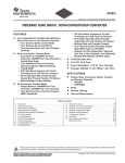
SPP System Wire Runs
SPP
1
1
External IR
Receiver
Keypad
VIA!NET
EXT IR
TO SENSE INPUTS
1
2
SS/SC4
3
1
VIA! SC4
or
SS1
USE STEREO 3.5mm PLUGS ONLY
4
5
6
ZONE
1
ZONE
1
5
TRIGGERS
1
2
3
4
5
6
7
8
1
ZONE
2
ZONE
6
AUDIO SENSOR
Sensors
Olé
POWER
ZONE
+
3
ZONE
--
7
3
1
ZONE
16VDC / 10A
4
ZONE
8
PWR10 16V/10A
Power Supply
TM
or
16VDC / 4A
3
16VDC/1.5A
PWR4 16V/4A
Power Supply
or
2
PWR1 16V/1A
Power Supply
To Video
Outputs
1
Cat-5: 22-24 AWG 4 Twisted-Pair Unshielded Cable
2
RG-59 Coaxial Cable: For Video
3
16 or 18 AWG 2-Conductor Stranded Wire: For VIA! Power
PV12
Rough-In
(Cutout Dimensions: 8"W x 10.5"H)
A new construction rough-in bracket (PBKT6P) is available for the SPP. The sliding frame on metal straps adjusts
to any location between studs. Adjust the straps and screw or nail the bracket to the stud as shown below.
INSTALLATION TIP:
The cardboard insert that is
packaged with the SPP can
be used as a cutout template.
PBKT6P
Rough-In
Bracket
Page 6
© ELAN Home Systems 2007 • All rights reserved.
ELAN
HOME
SPP
SYSTEMS
INSTALLATION MANUAL
The SPP frame is equipped with four "winglets" which, when tightened, clamp the frame securely against the
rough-in bracket or, in retrofit applications, against the drywall as shown in the figure below.
Remove front panel (4 screws)
in order to tighten winglets.
Frame
Winglets (4)
Front Panel
Trim-Out
All system wire runs are pulled through the SPP frame. Lay the SPP front panel on the floor in front of the frame
and make all your connections as shown below. Dress the wires in neat bundles––being careful not to pull off any
punchdown connections ––and then carefully place the front panel back into the frame and secure using the four
screws.
System Control
Wire Runs
VIA!NET
EXT IR
TO SENSE INPUTS
1
2
SS/SC4
3
USE STEREO 3.5mm PLUGS ONLY
4
5
6
2
3
4
ZONE
ZONE
1
5
TRIGGERS
1
ZONE
2
ZONE
5
6
7
POWER
ZONE
3
ZONE
+
8
6
ZONE
--
16VDC / 10A
4
7
ZONE
8
16VDC / 4A
ELAN Precision Panels save
time and make sense out
of complex wiring jobs!
16VDC/1.5A
© ELAN Home Systems 2007 • All rights reserved.
Page 7
SPP
ELAN
INSTALLATION MANUAL
HOME
SYSTEMS
Connections
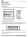
Rear Connections
RJ-45 Pin Out
ELAN recommends using ELAN C4545 and/or C45P RJ-45 interconnect cables for all Cat-5 connections to the
SPP. Should you prefer to terminate your own RJ45 cables, refer to the diagram below for the correct pin-out.
VIA!NET
EXT IR
TO SENSE INPUTS
1
Standard ELAN RJ-45 Pin-Out
2
4
5
ZONE
5
TRIGGERS
1
2
3
4
5
6
7
8
ZONE
2
ZONE
POWER
ZONE
FRONT
3
TAB
BLUE
WHITE/BLUE
ORANGE
WHITE/ORANGE
GREEN
WHITE/GREEN
BROWN
WHITE/BROWN
CABLE
6
1
PIN # COLOR CODE
1
2
3
4
5
6
7
8
SS/SC4
3
USE STEREO 3.5mm PLUGS ONLY
ZONE
ZONE
+
6
ZONE
--
16VDC / 10A
4
7
ZONE
8
16VDC / 4A
16VDC/1.5A
ELAN
Precision Panels
save time
and make sense
out of complex
wiring jobs!
SPP Punch-Down Connectors
The back of the SPP uses standard 110 punch-down connectors for all System and VIA!® Panel wire runs (with
the exception of speakers and coax). Wires do not need to be stripped prior to punchdown as the insulation will
automatically be displaced. Each punchdown row will accept two 24 or 22 AWG solid conductor wires. Use the
included 110 punch-down tool to properly make connections and avoid damaging the SPP.
110 Punch-Down Connector
NOTE: The SPP comes with Punch-down caps to ensure that wiring connections won’t come
loose.
NOTE: Do not mix wires of differing gauges on a single punchdown location as this may lead
to intermittent connectivity.
Page 8
© ELAN Home Systems 2007 • All rights reserved.
ELAN
HOME
SPP
SYSTEMS
INSTALLATION MANUAL
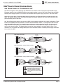
VIA!®Touch Panel Connections
Via! Touch Panel “A” Connections 16V
The SPP is designed to work flawlessly with ELAN VIA! Touch Panels. VIA! Touch Panels require ELAN 16 Volt
DC power supplies. Use the PWR10 16V/10A power supply to power up to ten VIA! Touch Panels. Use the PWR4
16V/4A power supply to power up to 4 VIA!s. Use the PWR1 16V/1A power supply to power 1 Via! Touch Panel.
When using a VIA! Valet, a PVIA1 Valet Wall Plate must be used. One PVIA Wall Plate is included with each VIA!
Valet. The installer has the option of using the included PVIA1 power supply or one of the other 16V power supplies to provide power to the Valet.
VIA! Touch Panels punch-down to the rear of the SPP at two locations, depending on system configuration. These
locations are labelled “ZXA 16V VIA!/OLÉ” and “ZXB 16V/12V VIA!/OLÉ” where “X” corresponds to the zone that
the touch panel(s) will control. Two touch panels can connect to each punch-down location for each zone. If
using more than 2 touch panels per location, make connections off of the SPP and use jumper wires to punchdown to the correct location. The diagram below shows the correct wiring for one touch panel in Zone 1 connected to the “A” location and utilizing 16VDC power from the PWR1, PWR4, or PWR10 power supply connected
to the front of the SPP.
SPP to VIA! Touch Panel
N/C
IR
X
485485+
G
16V
G
16V
Blue
White/Blue
Orange
White/Orange
Green
White/Green
Brown
White/Brown
Butt splice
or equivalent
Cat-5
SPP to PVIA1VALET (Using 16 VDC from SPP)
N/C
IR
X
485485+
G
16V
G
16V
Blue
White/Blue
Orange
White/Orange
Green
White/Green
Brown
White/Brown
Cat-5
Blue
White/Blue (IR)
Orange (485-)
White/Orange (485+)
Green (GND)
White/Green (+16V)
Brown (GND)
White/Brown (+16V)
Blue
White/Blue
Orange
White/Orange
Green
White/Green
Brown
White/Brown
nc
nc
nc
Blue
White/Blue
Orange
White/Orange
Green
White/Green
Brown
White/Brown
SPP to PVIA1VALET (Using 16 VDC from PVIA1)
nc
nc
nc
N/C
IR
X
485485+
G
16V
G
16V
X
X
Blue
White/Blue
Orange
White/Orange
Green
White/Green
Brown
White/Brown
Cat-5
Blue
White/Blue
Orange
White/Orange
Green
White/Green
Brown
White/Brown
X
X
PVIA-1
SIR
Z485Z485+
ST/SNS
IR
V485V485+
GND
+16V
GND
+16V
PVIA-1
SIR
Z485Z485+
ST/SNS
IR
V485V485+
GND
+16V
GND
+16V
nc
nc
nc
Blue
White/Blue
Orange
White/Orange
Green
White/Green
Brown
White/Brown
nc
nc
nc
Blue
White/Blue
Orange
White/Orange
Green
White/Green
Brown
White/Brown
VIA!
Touch
Panel
ELAN
C45P
VIA!
Touch
Panel
ELAN
C45P
VIA!
Touch
Panel
ELAN
C45P
When connecting a PVIA1 Valet
Wall Plate to the SPP, use either the
included PVIA1 power supply connected
to the PVIA1 Wall Plate, or a PWR10,
PWR4 or PWR1 power supply connected
to the SPP.
DO NOT USE BOTH POWER SUPPLIES!
© ELAN Home Systems 2007 • All rights reserved.
Page 9
SPP
ELAN
INSTALLATION MANUAL
HOME
SYSTEMS
Via!Touch Panel “B” Connection 16V
The diagram below shows VIA! Touch Panel connections when the “B” punch-down location is used.
NOTE: Place the “INT 12V/EXT 16V” switch in the DOWN (“EXT 16V”) position for this application. This
allows the external 16VDC power from the PWR1, PWR4, or PWR10 power supply connected to the front
of the SPP to reach the touch panel(s).
NOTE: Refer to the diagram on p. 9 for VIA!Valet6.4 connectivity. The “INT 12V/EXT 16V” switch will be
in the “EXT 16V” position.
INT 12V-EXT 16V Switch
The INT 12V-EXT 16V switch selects between internally generated voltage from the S Series Controller (+12
VDC) for use with Z•Pad Keypads and Olé Touchpads, or externally generated voltage from a +16 VDC power
supply connected to the front of the SPP Precision Panel to be utilized by Olé Touchpads and VIA!®Touch Panels.
This selection applies only to the "Z#B 16V/12V OLÉ/ZPAD" punchdown location. Select INT 12V (UP) when 12
VDC is required for keypads and touchpads. Select EXT 16V (DOWN) when using an external 16 VDC power supply for touch panels or touch pads.
SPP 16V/12V Switch
N/C
W/Bl
Or
W/Or
Gr INT
W/Gr
12V
Br
W/Br
EXT
16V
12V Switch (UP)
Z1B 16V/12V VIA!/OLÉ
Z1B 16V/12V VIA!/OLÉ
SPP 16V/12V Switch
N/C
W/Bl
Or
W/Or
Gr INT
W/Gr
12V
Br
W/Br
EXT
16V
16V Switch (DOWN)
Olé Film Interactive Touchpads
Olé Film Interactive Touchpads punch-down to the rear of the SPP at three locations, depending on system configuration. These locations are labelled “ZXA 16V VIA!/OLÉ”, “ZXB 16V/12V VIA!/OLÉ” and “ZXC 12V OLÉ/ZPAD”
where “X” corresponds to the zone that the touchpad(s) will control. Two touchpads can connect to each punchdown location for each zone. If using more than 2 touchpads per location, make connections off of the SPP and
use jumper wires to punch-down to the correct location. Olé Touchpads will operate using either 12V or 16V.
NOTE: Whenever Olé Touchpads are used with an S8 Series Controller (or with any system controller
that has a VIA!SC-4 or SS1 connected), set the switch on the rear of the touchpad to the “VIA!NET”
position.
Page 10
© ELAN Home Systems 2007 • All rights reserved.
ELAN
HOME
SYSTEMS
SPP
INSTALLATION MANUAL
Olé “A” Punchdown Locations-16V VNET
The diagram below shows connectivity to the “A” location when utilizing 16VDC power from a PWR1, PWR4, or
PWR10 16VDC power supply connected to the front of the SPP.
NOTE: The “A” punchdown location is always connected to the external 16VDC power from a PWR1,
PWR4, or PWR10 16VDC power supply connected to the front of the SPP.
IMPORTANT NOTE
Olé Touchpads
Use the correct power
supply connected to the front
of the SPP for the number
of Olé Touchpads and VIA!
Touch Panels in the system.
Olé “B” Punchdown Locations-16V VNET
The SPP Precision Panel has the ability to connect touchpanels, keypads and Olé Touchpads in various combinations in each zone. The “B” punchdown location can either pass 12VDC power from the S Series Controller
(Internal Power) or 16VDC from a power supply connected to the front of the SPP (External Power).
The diagram below shows connectivity to the “B” location when utilizing 16VDC power from a PWR1, PWR4, or
PWR10 16VDC power supply connected to the front of the SPP.
NOTE: Place the “INT 12V/EXT 16V” switch in the DOWN (“EXT 16V”) position for this application.
© ELAN Home Systems 2007 • All rights reserved.
Page 11
SPP
ELAN
INSTALLATION MANUAL
HOME
SYSTEMS
Olé “B” Punchdown Locations-12V VNET (S8.6 Only)
The diagram below shows connectivity to the “B” location when utilizing internal 12VDC power from an S8.6
Multi-Room Controller.
NOTE: Place the “INT 12V/EXT 16V” switch in the UP (“INT 12V”) position for this application.
IMPORTANT NOTE
Olés, Keypads
VSEs, & IR
Each ZONE INPUT
RJ45 Jack (except Z•630)
Provides 12VDC 300mA.
You may choose to load each of the
ZONE INPUTS
with any combination of Olés,
IR Receivers, or Electronic
Volume Controls as long as
the total current consumption
DOES NOT EXCEED 300mA.
(Z•630 not to exceed 200mA.)
Olé = 150mA
Keypad w/IR Tube = 65 mA
Z•025 = 85mA
Electronic Volume Control = 40mA
Additional IR Receivers = 10mA
Olé “C” Punchdown Locations-12V ZNET
There are two methods available when connecting Olé Touchpads as zone controllers in an S6/S12 based system.
Set the ZNET/VNET switch to the ZNET position and if using more than 2 touchpads per location, make connections off of the SPP and use jumper wires to punch-down to the correct location.
Method A
Punch the 485+ (Wh/Orange) and 485- (Green) wires down to the RS 485 Expansion block located below the SS/
SC4 switch as shown on the S6/S12 Overlay.
Method B
Remove the S6/S12 Overlay. Punch the 485+ (Wh/Orange) to the 485+ location on the SPP and punch the 485(Green) wire to the 485- location on the SPP as shown below.
Method A
Z1C 12V OLÉ/ZPAD
Blue
N/C
W/BL
White/Blue
N/C
Orange
N/C
White/Orange
N/C
Green
W/GR
White/Green
BR
Brown
N/C
White/Brown
Butt splice
or equivalent
Cat-5
Blue
White/Blue
Orange
White/Orange
Green
White/Green
Brown
White/Brown
Blue
White/Blue (IR)
Orange(Local IR)
White/Orange (485+)
Green (485-)
White/Green (+12V)
Brown (GND)
White/Brown
ELAN
C45P
RS 485 Expansion
White/Orange
W/OR
Green
GR
White/Orange
W/OR
Green
GR
White/Orange
W/OR
Green
GR
White/Orange
W/OR
Green
GR
Method B
Page 12
Z1C 12V OLÉ/ZPAD
Blue
N/C
IR
White/Blue
485Orange
485+
White/Orange
N/C
Green
12V
White/Green
G
Brown
N/C
White/Brown
Butt splice
or equivalent
Cat-5
Blue
White/Blue
Orange
White/Orange
Green
White/Green
Brown
White/Brown
Blue
White/Blue (IR)
Orange(Local IR)
White/Orange (485+)
Green (485-)
White/Green (+12V)
Brown (GND)
White/Brown
ELAN
C45P
© ELAN Home Systems 2007 • All rights reserved.
ELAN
HOME
SPP
SYSTEMS
INSTALLATION MANUAL
Z•Pad Connections
Keypad “C” Punchdown Locations-VNET (S8.6 Only)
It is possible to use ELAN Z•Pad keypads as zone controllers in an S8.6-based system. These keypads will control IR sources and S8.6 Controller function, but they WILL NOT receive RS-485 status feedback. This means that
source selection status, shared source status, etc. will not be available to these keypads. Source selection and
control are enabled and will function correctly.
NOTE: ELAN Z•PAD keypads will NOT receive status feedback when connected to the S8.6. DIP settings
on keypad are not required.
Keypad “C” Punchdown Locations-ZNET (S6/S12 Only)
There are two methods available when connecting ELAN Z•Pad keypads as zone controllers in an S6/S12 based
system. Set the ZNET/VNET switch to the ZNET position and if using more than 2 keypads per location, make
connections off of the SPP and use jumper wires to punch-down to the correct location. When using a VIA!SC-4
or SS1 System Station, set the SS/SC4 switch to the ON (Up) position and follow Method A.
Method A
Punch the 485+ (Wh/Orange) and 485- (Green) wires down to the RS 485 Expansion block located below the SS/
SC4 switch as shown on the S6/S12 Overlay.
Method B
Remove the S6/S12 Overlay. Punch the 485+ (Wh/Orange) to the 485+ loction on the SPP and punch the 485(Green) wire to the 485- location on the SPP as shown below. Use Method B only if there is no VIA!SC-4 or SS1
connected to the system.
Method A
Z1C 12V OLÉ/ZPAD
Blue
N/C
W/BL
White/Blue
N/C
Orange
N/C
White/Orange
N/C
Green
W/GR
White/Green
BR
Brown
N/C
White/Brown
Butt splice
or equivalent
Cat-5
Blue
White/Blue
Orange
White/Orange
Green
White/Green
Brown
White/Brown
Blue
White/Blue (IR)
Orange(Local IR)
White/Orange (485+)
Green (485-)
White/Green (+12V)
Brown (GND)
White/Brown
Keypad
ELAN
C45P
RS 485 Expansion
White/Orange
W/OR
Green
GR
White/Orange
W/OR
Green
GR
White/Orange
W/OR
Green
GR
White/Orange
W/OR
Green
GR
Method B
Z1C 12V OLÉ/ZPAD
Blue
N/C
IR
White/Blue
485Orange
485+
White/Orange
N/C
Green
12V
White/Green
G
Brown
N/C
White/Brown
Butt splice
or equivalent
Cat-5
© ELAN Home Systems 2007 • All rights reserved.
Blue
White/Blue
Orange
White/Orange
Green
White/Green
Brown
White/Brown
Blue
White/Blue (IR)
Orange(Local IR)
White/Orange (485+)
Green (485-)
White/Green (+12V)
Brown (GND)
White/Brown
Keypad
ELAN
C45P
Page 13
SPP
ELAN
INSTALLATION MANUAL
HOME
SYSTEMS
ZNET/VNET Switch
The ZNET-VNET switch selects between systems based on ELAN's ZNET (S6 and S12 Multi-Room Controllers)
and VNET ( S8 ). This switch will always be in the VNET position when installing the SPP with a S8 controller.
When using multiple SPPs, set the switch to the same position on each Precision Panel.
S6/S12
(ZNET)
S8.6
(VNET)
External Power Connections
Use the V+ and G screw terminal connections at the bottom edge of the SPP Precision Panel to connect 2 conductor wires (14-18 AWG) to power VIA! Touch Panels that DO NOT use the Cat-5 power wiring option and DO
use the external power connector located on the touch panel. This application is typically used for long wire runs
greater than 110 feet in length. It is not necessary to use both the Cat-5 power connections (located on the Zone
punchdown locations) and the External Power connectors described here.
SPP External
Power Connector
1
V+ G
2
V+ G
3
V+ G
4
V+ G
5
V+ G nc
16/18 AWG
2-Conductor
Wire
VIA!64
External
Power
Connector
Page 14
© ELAN Home Systems 2007 • All rights reserved.
ELAN
HOME
SPP
SYSTEMS
INSTALLATION MANUAL
IR Receiver Connections-Zone
Stand-alone IR receivers can easily connect to the SPP KP punch-downs. Connect +12V, IR, and GND to the
specific zone that is to be controlled.
Butt splice
or equivalent
N/C
W/Bl
Or
W/Or
Gr
W/Gr
Br
W/Br
Z1C 12V OLÉ/ZPAD
Zone 1C 12V OLÉ/ZPAD Connector
Blue
White/Blue
Orange
White/Orange
Green
White/Green
Brown
White/Brown
Blue
White/Blue
Orange
White/Orange
Green
White/Green
Brown
White/Brown
Cat-5
IR
IR Receiver
+12 VDC
GND
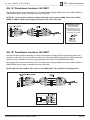
External IR Input (EXT IR IN) Connections
Use the External IR Input to send IR from a location that is not part of a zone
to the Ext. IR Input of the S12 or SS1 System Station in order to control system sources. By default, IR routed in
this way comes out all of the source IR Emitter Outputs and the ‘ALL’ IR Outputs simultaneously.
EXT IR
G
IR
G
Z1C 12V OLÉ/ZPAD
IR Receiver
GND
IR
+12VDC
N/C
IR
N/C
485+
IR
G
IR
G
IR
485-
SPP
12V
G
N/C
NOTE: A +12V connector on any of the Olé/ZPad punch-down connectors can be used to power the IR
receiver.
© ELAN Home Systems 2007 • All rights reserved.
Page 15
SPP
ELAN
INSTALLATION MANUAL
HOME
SYSTEMS
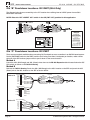
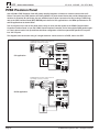
PVSE Precision Panel
Use of ELAN’s PVSE Precision Panel will greatly simplify integration of electronic volume controls with the S
Series. The back of the PVSE features six clearly labeled 110 punch-down blocks that provide independent connections for Override, IR and Sense; plus two additional punch-down connectors for easy routing of VSE IR signals to the SPP Precision Panel (SPP) EXT IR punch-down for S12 applications or the Zone punchdown for S6
and S8 applications as shown below.
Two RJ-45 jacks on the rear of the panel make it easy to route override signals to the PZ600 Communication
Controller Precision Panel or from the COM2 Communications Controller, and to link multiple PVSE panels together. There's also a bank of six dip switches that allow configuration of the front-panel VSE-specific IR Out ports
into 'ALL' IR ports.
The diagram below shows the wiring of a single electronic volume control to a PVSE, then to the SPP.
PVSE/SPP/Electronic Volume Control Connections
(speaker/amp connections not shown)
Wh/Brown (SENSE)
Brown (G)
Wh/Green (V+)
ELAN
C45P
Green (N/C)
Wh/Orange (N/C)
Orange (IR IN)
2A
Wh/Blue (IR OUT)
Blue (VCO)
VSE2
PVSE (Front)
PVSE
(Rear)
S12 application
VCO IRO IRI NC NC V+ G SENSE
VCO IRO IRI NC NC V+ G SENSE
VCO IRO IRI NC NC V+ G SENSE
VSE 3
VSE 2
VSE 1
VCO IRO IRI NC NC V+ G SENSE
VCO IRO IRI NC NC V+ G SENSE
VCO IRO IRI NC NC V+ G SENSE
SPP
EXT IR
VSE 5
VSE 6
G
VSE 4
IR
G
ALL
IR
G
IR ROUTING
See PVSE Manual for
dip-switch settings
1 2 3 4 5 6
IR
G
IR
OVERRIDE
OUT
OVERRIDE
IN
VSE IR
OUTPUTS
IR G IR G IR G G G
3
1
2
5
6
4
IR G IR G IR G G G
From
To Additional
PZ600/COM2
PVSEs
PVSE/SPP/Electronic Volume Control Connections
(speaker/amp connections not shown)
Wh/Brown (SENSE)
Brown (G)
Wh/Green (V+)
ELAN
C45P
Green (N/C)
Wh/Orange (N/C)
Orange (IR IN)
2A
Wh/Blue (IR OUT)
Blue (VCO)
VSE2
PVSE (Front)
PVSE
(Rear)
S6-S8 application
VCO IRO IRI NC NC V+ G SENSE
VCO IRO IRI NC NC V+ G SENSE
VCO IRO IRI NC NC V+ G SENSE
VSE 3
VSE 2
VSE 1
VCO IRO IRI NC NC V+ G SENSE
VCO IRO IRI NC NC V+ G SENSE
VCO IRO IRI NC NC V+ G SENSE
VSE 6
VSE 5
ALL
VSE 4
IR ROUTING
See PVSE Manual for
dip-switch settings
1 2 3 4 5 6
OVERRIDE
IN
VSE IR
OUTPUTS
N/C
W/Bl
Or
W/Or
Gr
W/Gr
Br
W/Br
Page 16
Z1C 12V OLÉ/ZPAD
SPP
OVERRIDE
OUT
IR G IR G IR G G G
3
1
2
5
6
4
IR G IR G IR G G G
From
To Additional
PZ600/COM2
PVSEs
© ELAN Home Systems 2007 • All rights reserved.
ELAN
HOME
SPP
SYSTEMS
INSTALLATION MANUAL
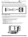
SPP to VSE100/VSE2 (No PVSE Precision Panel)
It is possible to connect electronic volume controls to a SPP without using a PVSE Precision Panel as the following diagram shows. IR, +12V, and GND are connected to the SPP (speaker/amp/override connections are not
shown).
Z1C 12V OLÉ/ZPAD
N/C
IR
N/C
485+
485-
12V
G
N/C
Blue
White/Blue
Orange
White/Orange
Green
White/Green
Brown
White/Brown
Cat-5
Blue
White/Blue
Orange
White/Orange
Green
White/Green
Brown
White/Brown
ELAN
C45P
VSE2
Sense Trigger Inputs
The Sense Trigger Inputs of the S Series are primarily for use with VIA!® Touch Panels. An ELAN™SENSE Sensor
can be connected that will cause VIA! Touch Panels to execute IR or serial commands. Use VIA!®Tools setup software to set up Trigger Input functionality. Wiring the Sense Inputs consists of punching down Voltage (V), Sense
(S), and Ground (G) as shown below.
ELAN™SENSE Sensors provide for a multitude of automation requirements:
• Audio Sensor: Detects line-level audio utilizing an RCA adaptor.
• Video Sensor: Detects Composite video utilizing an RCA adaptor.
• Light/LED Sensor: Detects ambiant light or
multi-color LEDs.
• Contact Closure Sensor: Detects closedcontact ON/OFF status.
• Current/Magnetic Sensor: Detects electric current through power cords or magnetic flyback.
• Voltage Sensor: Detects 3-24 Volts AC or DC.
• Doorbell Sensor: Detects multiple doorbell signals for advanced switching functionality.
SPP
SENSE 3
SENSE 4
SENSE 5
SENSE 2 SENSE 1
SENSE 5
SENSE 4
S
G
V
G
S
G
V
G
SENSE 6
SENSE 6
S
G
V
G
S
G
V
G
S
G
V
G
S
G
V
G
SENSE 3
Red
Black
AUDIO SENSOR
© ELAN Home Systems 2007 • All rights reserved.
White
Page 17
SPP
ELAN
INSTALLATION MANUAL
HOME
SYSTEMS
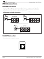
Front Connections
Zone Keypad Inputs
Connect a straight-through RJ-45 interconnect cable (ELAN C4545 1 or 2 meter) between the System Zone
Keypad Inputs and the SPP’s Zone 1-8 RJ-45 jacks. This routes all keypads, touch panels, and IR receivers
punched-down on the back of the SPP directly to the S Series chassis.
NOTE: In order to facilitate RS-485 communication, Zone 1 must ALWAYS be connected between the
System Controller and the SPP Precision Panel.
SPP to S6 Zone Keypad Connections (Zone 1 shown)
SPP to S8 Zone Connections (Zone 1 shown)
SPP
SPP
ZONE INPUTS
ZONE KEYPAD INPUTS
ZONE
ZONE
KP1
1
KP2
KP3
1
ELAN
C4545
ZONE 1
ZONE 2
ZONE 3
VIA!NET IN
ZONE 4
ZONE 5
ZONE 6
VIA!NET OUT
ELAN
C4545
KP4
KP5
KP6
S6
S8
SPP to S12 Zone Connections (Zone 1 shown)
SPP
ZONE INPUTS
ZONE
1
KP1
KP2
KP3
KP4
KP5
KP6
KP7
KP8
ELAN
C4545
S12
VIA!NET Connection
This RJ-45 connector is reserved for future use.
VIA!NET
Page 18
© ELAN Home Systems 2007 • All rights reserved.
ELAN
HOME
SPP
SYSTEMS
INSTALLATION MANUAL
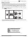
SS/SC4 Connection
Use the SS/SC4 RJ-45 connector to integrate an ELAN SS1 System Station or VIA!SC-4 System Controller to an
S Series Multi-Room Controller in order to facilitate integration of RS-232 controlled systems such as security,
lighting, or HVAC. Use an ELAN C4545 RJ-45 Interconnect Cable for this purpose. It is necessary to flip the DIP
switch on the rear of the SPP labeled SS/SC4 and NO SS/SC4 to the SS/SC4 (upper) position when connecting
to a VIA!SC-4 or SS1. Place the switch in the lower position (NO SS/SC4) when not connecting to a VIA!SC-4 or
SS1.
When connecting multiple SPPs and a VIA!SC-4 or SS1, connect the VIA!SC-4 or SS1 to SPP #1 and set the DIP
switch on each SPP to the SS/SC4 position.
SS/SC4 RJ-45
Connector
SS/SC4 Switch
SS/SC4 Connections (SS1/SC4 to SPP)
SS1
SPP
SS/SC4
VIA!NET
ELAN
C45P
SS/SC4
SS/SC4
or
NO SS/SC4
SPP
VIA!SC4
VIA!NET
ELAN
C45P
SS/SC4
NOTE: The SS/SC4 Connector on the SPP does not supply power for VIA!SC-4 applications. Use a PWR1
16 VDC external power supply to power the VIA!SC-4.
VIA!NET
EXT IR
TO SENSE INPUTS
1
2
SS/SC4
3
USE STEREO 3.5mm PLUGS ONLY
4
5
6
1
2
3
4
5
6
7
8
ZONE
ZONE
1
5
TRIGGERS
ZONE
2
ZONE
POWER
ZONE
3
ZONE
+
6
ZONE
--
16VDC / 10A
4
7
ZONE
8
16VDC / 4A
ELAN Precision Panels save
time and make sense out
of complex wiring jobs!
16VDC/1.5A
© ELAN Home Systems 2007 • All rights reserved.
Page 19
SPP
ELAN
INSTALLATION MANUAL
HOME
SYSTEMS
VIA!®Power
It is possible to connect and power up to ten VIA!® Touch Panels using the SPP and a PWR power supply. Use an
ELAN PWR1 16VDC/1.5 power supply for one VIA!® Touch Panel or 6 Olé Touchpads. Use an ELAN PWR4 16VDC/
4A power supply for up to four VIA!® Touch Panels or 27 Olé Touchpads. Use an ELAN PWR10 16VDC/10A power
supply for five to ten VIA!® Touch Panels or 66 Olé Touchpads.
NOTE: Only one power supply should be connected to the SPP at any one time!
16V/10A Power Supply Connections
16V/4A Power Supply Connections
POWER
POWER
--
+
+
16VDC / 10A
--
16VDC / 10A
16VDC
10.0A
16 VDC/
4A
16VDC / 4A
16VDC / 4A
ELAN PWR4
16V/4A
Power Supply
16VDC/1.5A
16VDC/1.5A
16V/1.5A Power Supply Connections
IMPORTANT NOTE
Olé Touchpads
and VIA! Touch Panels
POWER
+
PWR1
POWER
SUPPLY
--
Use the correct power
supply connected to the front
of the SPP for the number
of Olé Touchpads and VIA!
Touch Panels in the system.
16VDC / 10A
16VDC / 4A
ELAN PWR1
16V/1.5A
Power Supply
Olé = 150mA
VIA! = 1A
16VDC/1.5A
PWR1 = 1.5A
PWR4 = 4A
PWR10 = 10A
Trigger Connections
There are 8 mono 3.5mm Triggers connections on the front of the SPP Precision Panel. After punching down trigger connections on the back of the SPP, use a 3.5mm mono 'mini-to-mini' interconnect cable to connect to the S
Series Trigger Outputs as shown below. These can be used, for example, to mute/un-mute a specific VSE100 or
VSE2 etc. Consult your S Series installation manual for specific details on use of these connections.
S6 Rear
S8.6 Rear
S12 Rear
ZONE TRIGGER OUTPUTS
PROGRAMMABLE TRIGGER OUTPUTS
1
1
2
3
4
5
6
SPP Front
Page 20
4
5
6
SPP Front
SPP Front
TRIGGERS
3
3.5mm Mono
Interconnect
Cable
3.5mm Mono
Interconnect
Cable
3.5mm Mono
Interconnect
Cable
2
TRIGGERS
TRIGGERS
1
2
3
4
1
2
3
4
1
2
3
4
5
6
7
8
5
6
7
8
5
6
7
8
© ELAN Home Systems 2007 • All rights reserved.
ELAN
HOME
SPP
SYSTEMS
INSTALLATION MANUAL
To Sense Inputs
After punching-down sensors to the Sense Trigger Inputs on the rear of the SPP, simply plug 3.5 mm stereo
interconnect cables from the To Sense Inputs on the front of the SPP to the desired Sense Trigger Inputs of the
System Controller. Make absolutely sure to maintain correct input/output relationship (Sense 1 on the back of the
SPP must end up connected to Sense 1 on the System Controller).
SPP
SPP
TO SENSE INPUTS
TO SENSE INPUTS
1
2
1
3
4
6
5
3
USE STEREO 3.5mm PLUGS ONLY
USE STEREO 3.5mm PLUGS ONLY
4
2
5
6
3.5mm Stereo
Interconnect
Cable
3.5mm Stereo
Interconnect
Cable
S8.6
S12
ELAN SENSE INPUTS
1
2
3
4
5
6
EXT IR Connections
The External IR connector is a powerful feature that can enable specialized functionality in situations where system wide (not zone specific) IR control are needed in conjunction with a S12 or SS1 System Station. IR receiver
wire runs are punched down to the EXT IR 110 punchblock on the back of the SPP and a mono 3.5mm 'mini-tomini' interconnect cable is connected to the EXT IR connector on the S12 or SS1. See VIA!®TOOLS 'HELP' file for
information on EXT IR programming.
EXT IR
SPP
© ELAN Home Systems 2007 • All rights reserved.
3.5mm Mono
Interconnect
Cable
SS1 or S12
Page 21
SPP
ELAN
INSTALLATION MANUAL
HOME
SYSTEMS
Multi-Chassis Connections
When using more than one System chassis, an additional SPP Precison Panel per chassis is necessary. Connect
the Link In/Link Out RJ-45 jacks on the rear of the SPP's as shown below. ELAN recommends C4545 RJ-45
interconnect cables for these connections. See p. 19 for SS1/SC4 dipswitch settings when connecting multiple
SPP's.
SPP #3
SPP #1
LINK IN
LINK OUT
LINK IN
LINK OUT
ELAN
C4545
RJ-45
Interconnect
Cable
ELAN
C4545
RJ-45
Interconnect
Cable
LINK IN
ELAN
C4545
RJ-45
Interconnect
Cable
LINK OUT
LINK IN
SPP #2
LINK OUT
SPP #4
NOTE: When using multiple SPPs, always begin each succeeding chassis on the next Precision Panel. DO
NOT ‘span’ multiple chassis on a single SPP.
VIA!NET
EXT IR
TO SENSE INPUTS
1
2
SS/SC4
3
USE STEREO 3.5mm PLUGS ONLY
4
5
6
1
2
3
4
5
6
7
8
ZONE
ZONE
1
5
TRIGGERS
ZONE
2
ZONE
POWER
ZONE
3
ZONE
+
6
ZONE
--
16VDC / 10A
4
7
ZONE
8
16VDC / 4A
16VDC/1.5A
ELAN
Precision Panels
save time
and make sense
out of complex
wiring jobs!
Page 22
© ELAN Home Systems 2007 • All rights reserved.
ELAN
HOME
SPP
SYSTEMS
INSTALLATION MANUAL
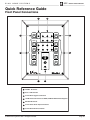
Quick Reference Guide
Front Panel Connections
7
VIA!NET
EXT IR
6
TO SENSE INPUTS
SS/SC4
{ }
1
1
2
3
5
USE STEREO 3.5mm PLUGS ONLY
4
5
6
ZONE
ZONE
1
5
TRIGGERS
1
2
3
4
5
6
7
8
ZONE
2
2
ZONE
POWER
ZONE
ZONE
ZONE
--
+
3
6
16VDC / 10A
4
2
7
ZONE
8
16VDC / 4A
16VDC/1.5A
®
3
4
1
VIA!NET RJ-45 Port
2
Zone 1-8 RJ-45 Ports
3
3.5mm Mono Triggers Connections
4
16 VDC Power Connections for PWR1, PWR4 & PWR10 Power Supplies
5
SS1/SC4 RJ-45 Port
6
3.5mm Stereo Sense Input Connections
7
3.5mm Mono EXT IR Connection
© ELAN Home Systems 2007 • All rights reserved.
Page 23
SPP
ELAN
INSTALLATION MANUAL
HOME
SYSTEMS
Rear Panel Connections
To/From additional SPP’s
(ELAN C4545 1 or 2 meter RJ-45 interconnect cables)
LINK IN
LINK OUT
N/C
IR
485485+
G
16V
G
16V
1
V+ G
2
V+ G
3
V+ G
485+
G
V INT
G
V
EXT
N/C
IR
485485+
G INT
V
G
V
EXT
4
V+ G
G
16V
G
16V
N/C
IR
N/C
IR
485-
485-
485+
485+
G
12V
G
N/C
G
16V
G
16V
N/C
IR
N/C
IR
485-
485-
485+
485+
G
12V
G
N/C
G
16V
G
16V
5
Page 24
485+
G
INT V
G
V
EXT
N/C
IR
485485+
G
INT V
G
V
EXT
N/C
IR
485485+
6
V+ G nc
nc V+ G
BLACK-
7
V+ G
8
V+ G
Z1C 12V OLÉ/ZPAD
Z1B 16V/12V VIA!/OLÉ
Z1A 16V VIA!/OLÉ
485-
INT G
V
G
V
EXT
485+
N/C
12V
G
N/C
N/C
IR
Z2C 12V OLÉ/ZPAD
485+
RED+
External IR
Receiver
485485+
N/C
12V
G
N/C
N/C
IR
485485+
N/C
12V
G
N/C
N/C
IR
485485+
N/C
12V
G
N/C
9
V+ G
Keypad
(Zone 1)
Z3C 12V OLÉ/ZPAD
485-
N/C
IR
485-
N/C
IR
485-
Z2B 16V/12V VIA!/OLÉ
G
G
V INT 12V
G
G
V
N/C
EXT
N/C
IR
NO SS/SC4
485+
G
INT V
G
V
EXT
N/C
IR
Z2A 16V VIA!/OLÉ
Z5C 12V OLÉ/ZPAD
485+
Cat-5
Z4C 12V OLÉ/ZPAD
Z8B 16V/12V VIA!/OLÉ
G
16V
G
16V
485+
485+
G
16V
G
16V
SS/SC4
N/C
IR
485-
Z3B 16V/12V VIA!/OLÉ
485+
485-
N/C
12V
G
N/C
485-
Z4B 16V/12V VIA!/OLÉ
Z7A 16V VIA!/OLÉ
N/C
IR
485-
485-
485+
S8.6/S12.8
(VNET)
Z3A 16V VIA!/OLÉ
Z7B 16V/12V VIA!/OLÉ
G
16V
G
16V
G
V INT
G
V
EXT
N/C
N/C
IR
IR
N/C
IR
Z4A 16V VIA!/OLÉ
485+
485+
485-
EXT IR
IR
G
IR
G
IR
G
IR
G
ZONES 1/2/3/4
N/C
IR
Z6C 12V OLÉ/ZPAD
N/C
IR
485-
485-
Z7C 12V OLÉ/ZPAD
Z6B 16V/12V VIA!/OLÉ
G
16V
G
16V
N/C
IR
Z8C 12V OLÉ/ZPAD
Z5B 16V/12V VIA!/OLÉ
485+
Z8A 16V VIA!/OLÉ
Cat-5
Olé Touch
Pad (Zone 7)
485-
Z6A 16V VIA!/OLÉ
VIA! Touch
Panel (Zone 5)
Z5A 16V VIA!/OLÉ
TM
N/C
IR
T1
G
T2
G
T3
G
T4
G
TRIGGERS 1/2/3/4
S6/S12
(ZNET)
ZONES 5/6/7/8
Cat-5
T5
G
T6
G
T7
G
T8
G
SENSE 2 SENSE 1
AUDIO SENSOR
S
G
V
G
S
G
V
G
SENSE 4 SENSE 3
Cat-5
S
G
V
G
S
G
V
G
TRIGGERS 5/6/7/8
TRIGGERS
SENSE INPUTS
S
G
V
G
S
G
V
G
SENSE 6 SENSE 5
ELAN™SENSE Sensor
(Sense Input 6)
10
V+ G
Cat-5
VC +/to COM2
+
Electronic
Volume Control
(Zone 4)
© ELAN Home Systems 2007 • All rights reserved.
ELAN
HOME
SYSTEMS
SPP
INSTALLATION MANUAL
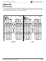
Appendix:
Rear Overlays
Prior to making any connections on the SPP, place the appropriate overlay on the rear of the Precision Panel for
the system type that is being installed. For System12 and System6-based installations, use the overlay called S6/
S12. For System8-based installations, use the overlay called S8.6.
S6/S12
© ELAN Home Systems 2007 • All rights reserved.
S8.6
Page 25
SPP
INSTALLATION MANUAL
ELAN
HOME
SYSTEMS
Notes:
Page 26
© ELAN Home Systems 2007 • All rights reserved.
ELAN
HOME
SYSTEMS
SPP
INSTALLATION MANUAL
Notes:
© ELAN Home Systems 2007 • All rights reserved.
Page 27
SPP
INSTALLATION MANUAL
ELAN
HOME
SYSTEMS
Notes:
Page 28
© ELAN Home Systems 2007 • All rights reserved.
Limited Warranty
ELAN HOME SYSTEMS L.L.C. ("ELAN") warrants the SPP Precision Panel to be free from defects in materials
and workmanship for the period of two years (2 years) from date of purchase. If within the applicable
warranty period above purchaser discovers that such item was not as warranted above and promptly notifies
ELAN in writing, ELAN shall repair or replace the item at the company's option. This warranty shall not apply
(a) to equipment not manufactured by ELAN, (b) to equipment which shall have been installed by other than an
ELAN authorized installer, (c) to installed equipment which is not installed to ELAN's specifications, (d) to equipment which shall have been repaired or altered by others than ELAN, (e) to equipment which shall have been
subjected to negligence, accident, or damage by circumstances beyond ELAN's control, including, but not
limited to, lightning, flood, electrical surge, tornado, earthquake, or other catastrophic events beyond ELAN's
control, or to improper operation, maintenance or storage, or to other than normal use of service. With respect
to equipment sold by, but not manufactured by ELAN, the warranty obligations of ELAN shall in all respects
conform to the warranty actually extended to ELAN by its supplier. The foregoing warranties do not cover
reimbursement for labor, transportation, removal, installation or other expenses which may be incurred in connection with repair or replacement.
Except as may be expressly provided and authorized in writing by ELAN, ELAN shall not be subject to any other
obligations or liabilities whatsoever with respect to equipment manufactured by ELAN or services rendered by
ELAN.
THE FOREGOING WARRANTIES ARE EXCLUSIVE AND IN LIEU OF ALL OTHER EXPRESSED AND IMPLIED
WARRANTIES EXCEPT WARRANTIES OF TITLE, INCLUDING BUT NOT LIMITED TO IMPLIED WARRANTIES
OF MERCHANTABILITY AND FITNESS FOR A PARTICULAR PURPOSE.
ATTENTION: TO OUR VALUED CONSUMERS
To ensure that consumers obtain quality pre-sale and after-sale support and service, ELAN Home
Systems products are sold exclusively through authorized dealers. ELAN products are not sold
online. The warranties on ELAN products are NOT VALID if the products have been purchased
from an unauthorized dealer or an online E-tailer. To determine if your ELAN reseller is
authorized, please call ELAN Home Systems at (859) 269-7760.
®
1300 E. New Circle Rd. Ste. 150 Lexington, KY 40509
www.elanhomesystems.com
P/N 9900878 REV:B