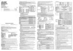
1
Inverter with built-in power regeneration function,
achieving great braking capability and reduction
in wiring length/space saving
The FR-A701 series, which is a high functional inverter FR-A700 series equipped with power
regeneration function, achieving great braking capability is now available. This compact body inverter
with variety of advanced technology attained high performance suitable for lift operation, line control,
etc. It contributes to high performance of machine equipment which generate regeneration torque such
as elevator, centrifugal separator, various testing machine, winding machine, etc.
Power regeneration
Energy flow at regeneration
FR-A701
Power
supply
1
• Standard
3
specifications
IM
• Outline
AC reactor
(FR-HAL equivalent)
Features
• Features
5
Dimension
Drawings
Inverter and power regeneration converter are integrated into one body to enclosure and it is easy to perform enclosure designing
Regeneration energy is returned
to power supply in this section.
FR-A
•The number of main circuit wires is down to approx. 40% and the installation area in case of 7.5K is down to approx. 60% as
compared to the conventional common converter stand-alone type. Reduction in wiring-length/space is enabled.
•In consideration of intercompatibility, installation size is kept the same as the conventional model (FR-A201 series).
•Since a braking circuit is built-in, it is not necessary to consider to select a braking unit.
360
Comparison (7.5K)
250
90
50
220
•Power regeneration provides great braking power by returning
regeneration energy from the motor to the power supply.
• Terminal Connection
Diagram
• Terminal Specification 10
Model configuration
:Installation area
FR-CV-7.5K
FR-A720-7.5K
FR - A721 - 5.5K
260
300
200V class
A741
400V class
155
555
100
Applied motor
(kW)
Three-phase
200V class
FR-A721Three-phase
400V class
FR-A741-
Main circuit wiring
: 6 lines only for input/output
Installation area ratio
: approx. 60%
High function/high performance elements of inverter are employed
FR-A
The inverter was developed based on the FR-A700 and is
equipped with the highest level of driving performance, long life
parts, life diagnostic function, network connection*2,
environmental friendly*1, easy operation*2, and easy maintenance.
*1: The EMC filter, which was built-in to FR-A700 series, is not available for this series.
*2: Because the FR Configurator has not worked with the FR-A701 series, a USB connector can not be used.
7.5
11
Symbol Applicable motor capacity
5.5K
55K
15 18.5 22
Indicate capacity
(kW)
30
37
45
55
300
200
• Protective
100
50
30
: Available models
• Option and
10
10
20
30
40
50
60
70
Peripheral Devices
80
• Precautions for
•Overhead crane
Operation/Selection
• Precautions for
FR-A
As compared with the combination of the conventional system
(inverter+power regeneration converter+AC reactor), total costreduction can be achieved. Since regeneration energy is returned
to the power supply, less heat is generated as compared to the
resistor driving method, and energy saving effect can be expected.
Trolley line
Electric
room
Motor
Operation
panel
IM
IM
Hoisting
motor
Traveling
motor
Traveling
motor
G
33
Peripheral Device
Selection
Trolley line
Overseas standard/EU restriction of the use of certain
hazardous substances (RoHS) directive compliance
Crane
IM
G
Traveling
wheel
• Warranty
37
Rail
FR-A
This product is certified by UL and cUL.
Complies with EN (LVD) standards. (400V class only)
Programmable
controller
FR-A701
W
• Service
• International 38
FA Center
Wide variety of lineup
FR-A
Wide variations from 5.5kW to 55kW for the 200V class and
400V class each are available.
1
26
Short time permissible regeneration power (kW)
•Multilevel car parking tower
Total cost-reduction can be achieved
24
Functions
(sec)
Applications
Motor
FR-A
Regenerative braking torque has enough allowance for
regeneration; 100% torque continuous and 150% torque 60s.
5.5
Main circuit wiring
: 16 lines for input/output
Installation area ratio
: approx. 100%
Power supply
Great braking capability by power regeneration function
30K
37K
45K
55K
• Parameter List 13
Operation time
A721
~
470
Symbol Voltage class
FR-CVL-7.5K
Motor
11K
15K
18.5K
22K
7.5K
5.5K
500
FR-A721-7.5K
Power supply
Explanation
Characteristic
2
Standard Specifications
Rating
200V class
Type FR-A721-
K
5.5
7.5
11
15
18.5
22
30
37
45
55
5.5
7.5
11
15
18.5
22
30
37
45
55
Rated capacity (kVA) *2
9.2
12.6
17.6
23.3
29
34
44
55
67
82
Rated current (A)
24
33
46
61
76
90
115
145
175
215
Output
Applicable motor capacity (kW) *1
150% 60s, 200% 3s (inverse time characteristics)
Overload current rating *3
surrounding air temperature 50°C
Voltage *4
Three-phase 200 to 240V
Power supply
Regenerative braking torque
100% continuous 150% 60s
Rated input
AC voltage/frequency
Three-phase 200 to 220V 50Hz, 200 to 240V 60Hz
Permissible AC voltage fluctuation
170 to 242V 50Hz,170 to 264V 60Hz
±5%
Permissible frequency fluctuation
Power supply capacity (kVA) *5
12
17
20
28
34
Protective structure (JEM 1030) *6
41
52
66
80
100
Open type (IP00)
Cooling system
Forced air cooling
Approx. mass (kg)
20
22
33
35
50
52
69
87
90
120
5.5
7.5
11
15
18.5
22
30
37
45
55
5.5
7.5
11
15
18.5
22
30
37
45
55
Rated capacity (kVA) *2
9.1
13
17.5
23.6
29
32.8
43.4
54
65
84
Rated current (A)
12
17
23
31
38
44
57
71
86
110
52
66
80
100
65
80
83
115
400V class
Type FR-A741-
K
Output
Applicable motor capacity (kW) *1
150% 60s, 200% 3s (inverse time characteristics)
Overload current rating *3
surrounding air temperature 50°C
Voltage *4
Three-phase 380 to 480V
Power supply
Regenerative braking torque
100% continuous 150% 60s
Rated input
AC voltage/frequency
Three-phase 380 to 480V 50Hz/60Hz
Permissible AC voltage fluctuation
323 to 528V 50Hz/60Hz
±5%
Permissible frequency fluctuation
Power supply capacity (kVA) *5
12
17
20
28
Protective structure *6
41
Open type (IP00)
Cooling system
Approx. mass (kg)
34
Forced air cooling
25
26
37
40
48
49
*1. The applicable motor capacity indicated is the maximum capacity applicable for use of the Mitsubishi 4-pole standard motor.
*2. The rated output capacity indicated assumes that the output voltage is 220V for 200V and 440V for 400V class.
*3. The % value of the overload current rating indicated is the ratio of the overload current to the inverter's rated output current. For repeated duty, allow time
for the inverter and motor to return to or below the temperatures under 100% load.
*4. The maximum output voltage does not exceed the power supply voltage. The maximum output voltage can be changed within the setting range. However,
the pulse voltage value of the inverter output side voltage remains unchanged at about 2 that of the power supply.
*5. The power supply capacity varies with the value of the power supply side inverter impedance (including those of the input reactor and cables).
*6. FR-DU07:IP40 (except for the PU connector)
3
Common Specifications
Soft-PWM control/high carrier frequency PWM control (selectable from among V/F control, advanced magnetic flux vector control and
real sensorless vector control) / vector control *1
0.2 to 400Hz (The maximum frequency is 120Hz under real sensorless vector control and vector control *1.)
Output frequency range
0.015Hz/0 to 60Hz (terminal 2, 4: 0 to 10V/12bit)
Frequency Analog input
0.03Hz/0 to 60Hz (terminal 2, 4: 0 to 5V/11bit, 0 to 20mA/about 11bit, terminal 1: 0 to ±10V/12bit)
setting
0.06Hz/0 to 60Hz (terminal 1: 0 to ±5V/11bit)
resolution
0.01Hz
Digital input
Within ±0.2% of the max. output frequency (25°C±10°C)
Frequency Analog input
accuracy
Within 0.01% of the set output frequency
Digital input
Voltage/frequency characteristics Base frequency can be set from 0 to 400Hz Constant torque/variable torque pattern or adjustable 5 points V/F can be selected
150% 0.3Hz (under real sensorless vector control or vector control)
Starting torque
Manual torque boost
Torque boost
Acceleration/deceleration time 0 to 3600s (acceleration and deceleration can be set individually), linear or S-pattern acceleration/deceleration mode, backlash
setting
measures acceleration/deceleration can be selected.
Operation frequency (0 to 120Hz), operation time (0 to 10s), operation voltage (0 to 30%) variable
DC injection brake
Operation current level can be set (0 to 220% adjustable), whether to use the function or not can be selected
Stall prevention operation level
Torque limit value can be set (0 to 400% variable)
Torque limit level
• Terminal 2, 4: 0 to 10V, 0 to 5V, 4 to 20mA (0 to 20mA) can be selected• Terminal 1: -10 to +10V, -5 to +5V can be selected
Frequency Analog input
setting
Input using the setting dial of the operation panel or parameter unit
Digital input
signal
Four-digit BCD or 16 bit binary (when used with option FR-A7AX)
Forward and reverse rotation or start signal automatic self-holding input (3-wire input) can be selected.
Start signal
You can select any twelve signals using Pr. 178 to Pr. 189 (input terminal function selection) from among multi speed selection, remote setting,
stop-on-contact, second function selection, third function selection, terminal 4 input selection, JOG operation selection, selection of
automatic restart after instantaneous power failure, flying start, external thermal relay input, PU operation/external inter lock signal , external
DC injection brake operation start, PID control enable terminal, brake opening completion signal, PU operation/external operation
switchover, load pattern selection forward rotation reverse rotation boost, V/F switching, load torque high-speed frequency, S-pattern
Input signals
acceleration/deceleration C switchover, pre-excitation, output stop, start self-holding selection, control mode changing, torque limit selection,
start-time tuning start external input, torque bias selection 1, 2 *1, P/PI control switchover, forward rotation command, reverse rotation
command, inverter reset, PTC thermistor input, PID forward reverse operation switchover, PU-NET operation switchover, NET-external
operation switchover, command source switchover, conditional position pulse train sign *1, conditional position droop pulse clear *1, and
magnetic flux decay output shutoff.
100kpps
Pulse train input
Maximum/minimum frequency setting, frequency jump operation, external thermal relay input selection, polarity reversible operation,
automatic restart after instantaneous power failure operation, electronic bypass operation, forward/reverse rotation prevention, remote
setting, brake sequence, second function, third function, multi-speed operation, original operation continuation at instantaneous power
Operational functions
failure, stop-on-contact control, load torque high speed frequency control, droop control, regeneration avoidance, slip compensation,
operation mode selection, offline auto tuning function, online auto tuning function, PID control, computer link operation (RS-485),
motor end orientation*1, pre-excitation, notch filter, easy gain tuning, speed feed forward, and torque bias*1
You can select any signals using Pr. 190 to Pr. 196 (output terminal function selection) from among inverter running, inverter running/start
command on, up-to-frequency, instantaneous power failure/undervoltage, overload warning, output frequency (speed) detection, second
output frequency (speed) detection, third output frequency (speed) detection, electronic thermal relay function pre-alarm, PU operation
mode, inverter operation ready 1, 2, output current detection, zero current detection, PID lower limit, PID upper limit, PID forward rotation
reverse rotation output, electronic bypass MC1, electronic bypass MC2, electronic bypass MC3, orientation complete*1, orientation
error*1, brake opening request, fan fault output, heatsink overheat pre-alarm, deceleration at an instantaneous power failure, PID control
Operating status
activated, during retry, PID output interruption, position control preparation ready*1, life alarm, power savings average value update
timing, current average monitor, fault output 1, 2, 3 (power-off signal), maintenance timer alarm, remote output, forward rotation output*1,
reverse rotation output*1, low speed output, torque detection, regenerative status output *1, start-time tuning completion, in-position
completion*1, alarm output and fault output. Open collector output (5 points), relay output (2 points) and alarm code of the inverter can be
output (4 bit) from the open collector.
In addition to the above, you can select any signals using Pr. 313 to Pr. 319 (extension output terminal function selection) from among control
When used with the
circuit capacitor life, main circuit capacitor life, cooling fan life, inrush current limit circuit life. (only positive logic can be set for extension
FR-A7AY, FR-A7AR
(option)
terminals of the FR-A7AR)
50kpps
Pulse train output
You can select any signals using Pr. 54 FM terminal function selection (pulse train output) and Pr. 158 AM terminal function selection (analog
output) from among output frequency, motor current (steady or peak value), output voltage, frequency setting, operation speed, motor
torque, converter output voltage (steady or peak value), electronic thermal relay function load factor, input power, output power, load
Pulse/analog output
meter, motor excitation current, reference voltage output, motor load factor, power saving effect, PID set point, PID measured value,
motor output, torque command, torque current command, and torque monitor.
Output frequency, motor current (steady or peak value), output voltage, frequency setting, running speed,motor torque, overload,
converter output voltage (steady or peak value), electronic thermal relay function load factor, input power, output power, load meter,
motor excitation current, cumlative energization time, actual operation time, motor load factor, cumulative power, energy saving effect,
Operating status cumulative saving power, PID set point, PID measured value, PID deviation, inverter I/O terminal monitor, input terminal option
PU
(FR-DU07/
monitor*2, output terminal option monitor*2, option fitting status*3, terminal assignment status*3, torque command, torque current
FR-PU07/
command, feed back pulse*1,motor output
FR-PU04)
Fault definition is displayed during the fault occurs, the output voltage/current/frequency/cumulative energization time right before the
Fault definition
fault occurs and past 8 fault definitions are stored.
Interactive guidance Function (help) for operation guide*3
Overcurrent during acceleration, overcurrent during constant speed, overcurrent during deceleration, overvoltage during acceleration,
overvoltage during constant speed, overvoltage during deceleration, inverter protection thermal operation, motor protection thermal
operation, heatsink overheat, instantaneous power failure occurrence, undervoltage, input phase failure, motor overload, output side
earth (ground) fault overcurrent, output short circuit, main circuit element overheat, output phase failure, external thermal relay
operation*5, PTC thermistor operation*5, option alarm, parameter error, PU disconnection, retry count excess*5, CPU alarm, operation
panel power supply short circuit, 24VDC power output short circuit, output current detection value excess*5, inrush current limit circuit
Protective/warning function
alarm, communication alarm (inverter), opposite rotation deceleration error*5, analog input error, fan fault, overcurrent stall prevention,
overvoltage stall prevention, electronic thermal relay function prealarm, PU stop, maintenance timer alarm*2*5, parameter write error,
copy operation error, operation panel lock, parameter copy alarm, speed limit indication, signal loss detection*1*5, speed deviation
large*1*5, overspeed*1*5, excessive position error*1*5, encoder phase error*1*5, regeneration converter overcurrent, regeneration
converter circuit fault, regeneration converter transistor protection thermal, brake sequence error*5
-10°C to +50°C (non-freezing)
Ambient temperature
90%RH maximum (non-condensing)
Ambient humidity
-20°C to +65°C
Storage temperature*4
Indoors (without corrosive gas, flammable gas, oil mist, dust and dirt etc.)
Atmosphere
*1
*2
*3
*4
*5
Standard
Specifications
Outline
Dimension
Drawings
Terminal Connection
Diagram
Terminal Specification
Explanation
Parameter
List
Instructions
Warranty
Maximum 1000m above sea level, 5.9m/s2 or less
Available only when the option (FR-A7AP) is mounted.
Can be displayed only on the operation panel (FR-DU07).
Can be displayed only on the parameter unit (FR-PU07/FR-PU04).
Temperature applicable for a short period in transit, etc.
This protective function does not function in the initial status.
Altitude/vibration
Inquiry
Environment
Indication
Options
Protective
Functions
Output signals
Operation specifications
Control specifications
Features
Control method
4
Outline Dimension Drawings
FR-A721-5.5K, 7.5K
FR-A741-5.5K, 7.5K
10
425
454
470
2-φ10 hole
2.3
190
250
270
Inverter Type
D1
D2
FR-A721-5.5K, 7.5K
FR-A741-5.5K, 7.5K
163
168
90
85
100
D1
170
D2
205
234
(Unit: mm)
540
575
600
2- φ10 hole
15
FR-A721-11K, 15K
FR-A741-11K, 15K
220
300
3.2
10
10
294
Inverter Type
FR-A721-11K, 15K
FR-A741-11K, 15K
D1
D2
213
224
64
53
125
D1
169
D2
255
284
5
(Unit: mm)
15
2- φ12 hole
Features
FR-A721-18.5K, 22K
FR-A741-18.5K, 22K
W1
W
Standard
Specifications
Outline
Dimension
Drawings
3.2
10
12
535
575
600
FAN
320
FR-A721-18.5K, 22K
FR-A741-18.5K, 22K
D1
D2
W
W1
W2
W3
219
238
84
65
390
360
290
260
345
315
370
340
130
Terminal Connection
Diagram
Terminal Specification
Explanation
Inverter Type
D1
190
D2
W2
Parameter
List
W3
(Unit: mm)
15
2- φ12 hole
Protective
Functions
FR-A721-30K
FR-A741-30K
350
450
Options
700
635
Instructions
12
10
675
FAN
340
D1
D2
240.5
252.5
82.5
70.5
Warranty
Inverter Type
FR-A721-30K
FR-A741-30K
145
D1
195
D2
405
Inquiry
430
(Unit: mm)
6
15
FR-A721-37K, 45K
FR-A741-37K, 45K
2- φ14 hole
3.2
368
Inverter Type
FR-A721-37K, 45K
FR-A741-37K, 45K
163
D1
205
D2
370
470
405
15
14
630
670
700
FAN
D1
D2
257.5
281.5
93.5
69.5
450
(Unit: mm)
15
FR-A721-55K
FR-A741-55K
2- φ14 hole
15
14
480
600
830
900
870
FAN
3.2
405
Inverter Type
FR-A721-55K
FR-A741-55K
D1
D2
312
324.5
76
64
190
D1
215
D2
555
580
(Unit: mm)
7
Heatsink protrusion procedure
Features
When encasing the inverter in an enclosure, the generated heat amount in an enclosure can be greatly reduced by installing
the heatsink portion of the inverter outside the enclosure.
When installing the inverter in a compact enclosure, etc., this installation method is recommended.
Protrusion of heatsink
Standard
Specifications
Panel cutting
Cut the panel of the enclosure according to the inverter capacity.
H2
H3
C
FR-A721-5.5K, 7.5K
FR-A741-5.5K, 7.5K
240
190
454
434
12
8
M8
FR-A721-11K, 15K
FR-A741-11K, 15K
290
220
575
548
17
10
M8
FR-A721-18.5K, 22K
376
290
575
546
17
12
M10
FR-A741-18.5K, 22K
346
260
575
546
17
12
M10
FR-A721-30K
FR-A741-30K
436
350
675
646
17
12
M10
FR-A721-37K, 45K
FR-A741-37K, 45K
456
370
670
641
17
12
M12
FR-A721-55K
FR-A741-55K
586
480
870
841
17
12
M12
Parameter
List
H1
Protective
Functions
H
Options
W1
Instructions
W
Warranty
Inverter Type
Inquiry
W1
W
H2
Terminal Connection
Diagram
Terminal Specification
Explanation
H
H1
Outline
Dimension
Drawings
H3
4-C screw
8
Shift and removal of a rear side installation frame
One installation frame is attached to each of the upper and lower parts of the inverter. Change the position of the
rear side installation frame on the upper and lower sides of the inverter to the front side as shown on the right.
When changing the installation frames, make sure that the installation orientation is correct.
Shift
Upper
installation
frame
Lower installation frame
Shift
Installation of the inverter
Push the inverter heatsink portion outside the enclosure and fix the enclosure and inverter with upper and lower
installation frame.
Enclosure
Inside the
enclosure Exhausted air
Inverter
Installation
frame
Cooling
wind
D1
Inverter Type
FR-A721-5.5K, 7.5K
FR-A741-5.5K, 7.5K
FR-A721-11K, 15K
FR-A741-11K, 15K
FR-A721-18.5K, 22K
FR-A741-18.5K, 22K
FR-A721-30K
FR-A741-30K
FR-A721-37K, 45K
FR-A741-37K, 45K
FR-A721-55K
FR-A741-55K
D1
100
125
130
145
163
190
Dimension of the outside of the
enclosure
CAUTION
· Having a cooling fan, the cooling section which comes out of the enclosure can not be used in the environment of water
drops, oil, mist, dust, etc.
· Be careful not to drop screws, dust, etc. into the inverter and cooling fan section.
9
Terminal Connection Diagram
P/+
Output stop
Reset
Terminal 4 input selection
(Current input selection)
Selection of automatic restart
after instantaneous
power failure
Contact input common
24VDC power supply
(Common for external power supply transistor)
Frequency setting
potentiometer
1/2W1kΩ
*5
C2
RH
Relay output 2
A2
RL
JOG *2
RUN
*4. Terminal input specifications
can be changed by analog
input specifications
switchover (Pr. 73, Pr. 267).
Set the voltage/current input
switch in the OFF position to
select voltage input (0 to 5V/0
to10V) and ON to select
current input (4 to 20mA).
2
1
RT
SU
MRS
IPF
RES *3
*5. It is recommended to use 2W1kΩ
when the frequency setting signal
is changed frequently.
Standard
Specifications
Overload
FU
Frequency detection
CS PTC
SD
SE
PU
connector
USB
connector
+
- Indicator
(Frequency meter, etc.)
Moving-coil type
1mA full-scale
FM
SD
Calibration
resistor *7
AM
5
TXD+
4 to 20mADC (Initial value)
0 to 5VDC selected *4
0 to 10VDC
TXD-
(+) Analog signal output
(0 to 10VDC)
(-)
RS-485 terminals
Data transmission
RXD+
RXD-
Option connector 1
SG
Option connector 2
Option connector 3
using Pr.291.
*9. Because the FR Configurator has not
worked with the FR-A701 series, a USB
connector can not be used.
*8
*9
Open collector output common
Sink/source common
*7. It is not necessary when *8. FM terminal can be
used for pulse train
calibrating the indicator
output of open
from the operation panel.
collector output
PC
4
Connector
for plug-in option
connection
Terminal functions
Up to frequency vary with the output
terminal assignment
Instantaneous (Pr. 190 to Pr. 194)
power failure
OL
AU
0 to ±10VDC (Initial value)
1
0 to ±5VDC selected *4
Auxiliary (+)
input (-)
Terminal
4 input (+)
(Current (-)
input)
Open collector output
Running
Terminal Connection
Diagram
Terminal Specification
Explanation
B2
RM
AU
Outline
Dimension
Drawings
A1
input switch
4 2
10E(+10V)
ON
OFF
10(+5V)
0 to 5VDC (Initial value)
2 0 to 10VDC selected
*4
0 to 20mADC
5
(Analog common)
3
Terminal functions
Relay output 1 vary with the output
(Fault output) terminal assignment
(Pr. 195, Pr. 196)
STOP
*4 Voltage/current
Frequency setting signal (Analog)
B1
Parameter
List
Second function selection
Relay output
Protective
Functions
Jog mode
STR
C1
Options
Low speed
STF
SINK
Middle
speed
*6. Do not connect any options to P/+ and
N/-.
Control circuit
SOURCE
Control input signals (No voltage input allowed)
Forward
Terminal functions vary with
rotation
the input terminal
start
assignment (Pr. 178 to Pr. 189) Reverse
rotation
start
Start selfholding selection
High speed
Multi-speed
selection
Earth (Ground)
Main circuit
Earth
(Ground)
Motor
IM
Instructions
*1
*1. To supply power to the
control circuit separately,
remove the jumper across
R1/L11 and S1/L21.
U
V
W
R1/L11
S1/L21
Jumper
*3. AU terminal can be
used as PTC input
terminal.
*6
R/L1
S/L2
T/L3
Three-phase AC
power supply
*2. JOG terminal can be used
as pulse train input terminal.
Use Pr. 291 to select
JOG/pulse.
N/-
*6
MC
MCCB
Terminating
resistor VCC
Data reception
GND
Warranty
Control circuit terminal
Features
Sink logic
Main circuit terminal
5V (Permissible load
current 100mA)
CAUTION
⋅ To prevent a malfunction caused by noise, separate the signal cables more than 10cm from the power cables. Also separate the main circuit wire
of the input side and output side.
⋅ After wiring, wire offcuts must not be left in the inverter.
Inquiry
Wire offcuts can cause an alarm, failure or malfunction. Always keep the inverter clean.
When drilling mounting holes in an enclosure etc., take care not to allow chips and other foreign matter to enter the inverter.
· Set the voltage/current input switch correctly. Different setting may cause a fault, failure or malfunction.
10
Terminal Specification Explanation
Type
Terminal Symbol
Terminal Name
DC terminal
Description
Connect to the commercial power supply.
Connect a three-phase squirrel-cage motor.
Connected to the AC power supply terminals R/L1 and S/L2. To retain the fault display and
fault output, remove the jumpers from terminals R/L1-R1/L11 and S/L2-S1/L21 and apply
external power to these terminals.
Do not turn off the power supply for control circuit (R1/L11, S1/L21) with the main circuit
power (R/L1, S/L2, T/L3) on. Doing so may damage the inverter. The circuit should be
configured so that the main circuit power (R/L1, S/L2, T/L3) is also turned off when the
power supply for control circuit (R1/L11, S1/L21) is off.
Power supply capacity for the 15K or less is 90VA and for the 18.5K or more is 100VA.
Do not connect an option directly to P/+, N/-
Earth (Ground)
For earthing (grounding) the inverter chassis. Must be earthed (grounded).
STF
Forward rotation start
STR
Reverse rotation start
Turn on the STF signal to start forward
rotation and turn it off to stop.
Turn on the STR signal to start reverse
rotation and turn it off to stop.
Main circuit
R/L1, S/L2, T/L3 AC power input
U, V, W
Inverter output
R1/L11, S1/L21
P/+, N/-
STOP
RH, RM, RL
JOG
RT
MRS
Contact input
RES
AU
Control circuit/input signals
CS
SD
PC
10E
10
Frequency setting
2
4
1
5
11
Power supply for control
circuit
Start self-holding
selection
Multi-speed selection
When the STF and STR signals are turned on
simultaneously, the stop command is given.
Turn on the STOP signal to self-hold the start signal.
Multi-speed can be selected according to the combination of RH, RM and RL signals.
Turn on the JOG signal to select Jog operation (initial setting) and turn on the start signal
(STF or STR) to start Jog operation.
JOG terminal can be used as pulse train input terminal. To use as pulse train input terminal,
Pulse train input
the Pr. 291 setting needs to be changed. (maximum input pulse: 100kpulses/s)
Turn on the RT signal to select second function.
Second function selection When the second function such as "second torque boost" and "second V/F (base
frequency)" are set, turning on the RT signal selects these functions.
Turn on the MRS signal (20ms or more) to stop the inverter output.
Output stop
Use to shut off the inverter output when stopping the motor by electromagnetic brake.
Used to reset fault output provided when fault occurs.
Turn on the RES signal for more than 0.1s, then turn it off.
Reset
Initial setting is for reset always. By setting Pr. 75, reset can be set to enabled only at fault
occurrence. Recover about 1s after reset is cancelled.
Terminal 4 is made valid only when the AU signal is turned on. (The frequency setting signal
Terminal 4 input selection can be set between 4 and 20mADC.)
Turning the AU signal on makes terminal 2 (voltage input) invalid.
AU terminal is used as PTC input terminal (thermal protection of the motor). When using it
PTC input
as PTC input terminal, set the AU/PTC switch to PTC.
Jog mode selection
Selection of automatic
restart after instantaneous
power failure
Contact input common
(sink) (initial setting)
External transistor
common (source)
24VDC power supply
common
External transistor
common (sink)
(initial setting)
Contact input common
(source)
24VDC power supply
When the CS signal is left on, the inverter restarts automatically at power restoration. Note
that restart setting is necessary for this operation. In the initial setting, a restart is disabled.
Common terminal for contact input terminal (sink logic) and terminal FM.
When connecting the transistor output (open collector output), such as a programmable
controller, when source logic is selected, connect the external power supply common for
transistor output to this terminal to prevent a malfunction caused by undesirable currents.
Common output terminal for 24VDC 0.1A power supply (PC terminal).
Isolated from terminals 5 and SE.
When connecting the transistor output (open collector output), such as a programmable
controller, when sink logic is selected, connect the external power supply common for
transistor output to this terminal to prevent a malfunction caused by undesirable currents.
Common terminal for contact input terminal (source logic).
Can be used as 24VDC 0.1A power supply.
When connecting the frequency setting potentiometer at an 10VDC, Permissible load
current 10mA
5VDC, Permissible load
connecting it to terminal 10E.
current 10mA
Inputting 0 to 5VDC (or 0 to 10V, 0 to 20mA) provides the
maximum output frequency at 5V (10V, 20mA) and makes
input and output proportional. Use Pr. 73 to switch from
among input 0 to 5VDC (initial setting), 0 to 10VDC, and 0 Voltage input:
to 20mA.
Input resistance 10kΩ ± 1kΩ
Set the voltage/current input switch in the ON position to
Maximum permissible voltage
select current input (0 to 20mA).
Inputting 4 to 20mADC (or 0 to 5V, 0 to 10V) provides the 20VDC
Current input:
maximum output frequency at 20mA makes input and
output proportional. This input signal is valid only when the Input resistance 245Ω ± 5Ω
AU signal is on (terminal 2 input is invalid). Use Pr. 267 to
Maximum permissible current
switch from among input 4 to 20mA (initial setting), 0 to
5VDC, and 0 to 10VDC. Set the voltage/current input switch 30mA
in the OFF position to select voltage input (0 to 5V/0 to
10V).
Use Pr. 858 to switch terminal functions.
Inputting 0 to ±5 VDC or 0 to ±10VDC adds this signal to terminal 2 or 4 frequency setting
signal. Use Pr. 73 to switch between the input 0 to ±5VDC and 0 to ±10VDC (initial setting).
Use Pr. 868 to switch terminal functions.
Input resistance 10kΩ ± 1kΩ
Maximum permissible voltage ± 20VDC
Common terminal for frequency setting signal (terminal 2, 1 or 4) and analog output terminal
AM. Do not earth (ground).
Frequency setting power initial status, connect it to terminal 10.
Change the input specifications of terminal 2 when
supply
Frequency setting
(voltage)
Frequency setting
(current)
Frequency setting
auxiliary
Frequency setting
common
Up to frequency
OL
Overload warning
IPF
FU
SE
Instantaneous power
failure
Frequency detection
Open collector output
common
Pulse
For meter
FM
NPN open collector
AM
terminals
--------------------
RS-485
Communication
Analog
output
Analog signal output
PU connector
TXD+
Inverter transmission
TXDRXD+
terminal
Inverter reception
RXDSG
terminal
Earth (Ground)
Common terminal for terminals RUN, SU, OL, IPF, FU
Output item: Output frequency (initial setting)
Permissible load current 2mA
1440pulses/s at 60Hz
Signals can be output from the open collector
terminals by setting Pr. 291.
(Maximum output pulse: 50kpulses/s
Permissible load current : 80mA)
Output item: Output frequency (initial setting)
Output signal 0 to 10VDC
Permissible load current 1mA
(load impedance 10kΩ or more) Resolution 8 bit
With the PU connector, communication can be made through RS-485.
(for connection on a 1:1 basis only)
⋅ Conforming standard
: EIA-485 (RS-485)
⋅ Transmission format
: Multidrop link
⋅ Communication speed
: 4800 to 38400bps
⋅ Overall length
: 500m
Features
SU
Standard
Specifications
Inverter running
Outline
Dimension
Drawings
RUN
Terminal Connection
Diagram
Terminal Specification
Explanation
Relay output 2
Select one e.g. output
frequency from monitor items.
(Not output during inverter
reset.)
The output signal is
proportional to the magnitude
of the corresponding
monitoring item.
Parameter
List
(alarm output)
A2, B2, C2
Open collector
Control circuit/output signals
Relay output 1
Description
1 changeover contact output indicates that the inverter protective function has
activated and the output stopped.
Abnormal: No conduction across B-C (Across A-C Continuity),
Normal: Across B-C Continuity (No conduction across A-C)
Contact capacity: 230VAC 0.3A (Power factor = 0.4) 30VDC 0.3A
1 changeover contact output
Contact capacity: 230VAC 0.3A (Power factor = 0.4) 30VDC 0.3A
Switched low when the inverter output frequency is
equal to or higher than the starting frequency (initial
value 0.5Hz). Switched high during stop or DC
injection brake operation. *
Switched low when the output frequency
reaches within the range of ±10% (initial
Permissible load 24VDC
value) of the set frequency. Switched
(27VDC maximum) 0.1A
high during acceleration/deceleration
(A voltage drop is 2.8V
and at a stop. *
maximum when the signal is
Switched low when stall prevention is
on.)
activated by the stall prevention
* Low indicates that the open
function. Switched high when stall
Alarm code
collector output transistor is on
prevention is cancelled. *
(4bit) output
(conducts).
Switched low when an instantaneous
High indicates that the transistor
power failure and under voltage
is off (does not conduct).
protections are activated. *
Switched low when the inverter output
frequency is equal to or higher than
the preset detected frequency and
high when less than the preset
detected frequency. *
Protective
Functions
A1, B1, C1
Terminal Name
With the RS-485 terminals, communication can be made through RS-485.
Conforming standard
: EIA-485 (RS-485)
Transmission format
: Multidrop link
Communication speed
: 300 to 38400bps
Overall length
: 500m
Options
Terminal Symbol
Relay
Type
CAUTION
Instructions
⋅ Set Pr. 73, Pr. 267, and a voltage/current input switch correctly, then input an analog signal in accordance with the setting.
Applying a voltage signal with voltage/current input switch on (current input is selected) or a current signal with switch off (voltage input is selected) could
cause component damage of the inverter or analog circuit of signal output devices.
⋅ The inverter will be damaged if power is applied to the inverter output terminals (U, V, W). Never perform such wiring.
Inquiry
Warranty
⋅
indicates that terminal functions can be selected from Pr.178 to Pr.196 (I/O terminal function selection).
⋅ Terminal names and terminal functions are those of the factory set.
12
Parameter List
For simple variable-speed operation of the inverter, the initial setting of the parameters may be used as they are. Set the
necessary parameters to meet the load and operational specifications. Parameter setting, change and check can be made
from the operation panel (FR-DU07).
REMARKS
⋅ indicates simple mode parameters. (initially set to extended mode)
⋅The shaded parameters in the table allow its setting to be changed during operation even if "0" (initial value) is set in Pr.77 Parameter write selection.
0 to 30%
0.1%
3/2% *1
Maximum frequency
0 to 120Hz
0.01Hz
120Hz
2
Minimum frequency
0 to 120Hz
0.01Hz
0Hz
3
Base frequency
0 to 400Hz
0.01Hz
60Hz
4
Multi-speed setting (high speed)
0 to 400Hz
0.01Hz
60Hz
5
Multi-speed setting (middle speed)
0 to 400Hz
0.01Hz
30Hz
6
Multi-speed setting (low speed)
0 to 400Hz
0.01Hz
10Hz
7
Acceleration time
0 to 3600/360s
0.1/0.01s
5/15s *1
8
Deceleration time
0 to 3600/360s
0.1/0.01s
5/15s *1
9
Electronic thermal O/L relay
0 to 500A
0.01A
Rated
inverter
current
10
11
DC injection brake operation frequency
DC injection brake operation time
0 to 120Hz, 9999
0 to 10s, 8888
0.01Hz
0.1s
3Hz
0.5s
12
DC injection brake operation voltage
0 to 30%
0.1%
4/2% *1
⎯
⎯
13
14
Starting frequency
Load pattern selection
0 to 60Hz
0 to 5
0.01Hz
1
0.5Hz
0
15
Jog frequency
0 to 400Hz
0.01Hz
5Hz
16
Jog acceleration/deceleration time
0 to 3600/360s
0.1/0.01s
0.5s
⎯
⎯
⎯
17
18
19
0, 2, 4
120 to 400Hz
0 to 1000V, 8888, 9999
1
0.01Hz
0.1V
0
120Hz
9999
20
MRS input selection
High speed maximum frequency
Base frequency voltage
Acceleration/deceleration reference
frequency
1 to 400Hz
0.01Hz
60Hz
1
0
22
0 to 400%
0.1%
150%
0 to 200%, 9999
0.1%
9999
Multi-speed setting (4 speed to 7 speed)
0 to 400Hz, 9999
0.01Hz
9999
Multi-speed input compensation selection
Acceleration/deceleration pattern
0, 1
1
0
0 to 5
1
0
0 to 400Hz, 9999
0 to 400Hz, 9999
0 to 400Hz, 9999
0 to 400Hz, 9999
0 to 400Hz, 9999
0 to 400Hz, 9999
0, 1 to 9998
0 to 100%
0 to 400Hz
0.01Hz
0.01Hz
0.01Hz
0.01Hz
0.01Hz
0.01Hz
1
0.1%
0.01Hz
9999
9999
9999
9999
9999
9999
0
10%
6Hz
0 to 400Hz, 9999
0.01Hz
9999
21
23
24 to 27
⎯
28
⎯
29
Frequency
jump
Multi-speed
setting
Basic function
Torque boost
1
DC
injection
brake
Initial Value
Jog
operation
Minimum
Setting
Increment
Acceleration/
deceleration
time
Setting Range
0
Frequency
detection
⎯
13
Name
Parameter
Stall
prevention
Func
tion
31
32
33
34
35
36
37
41
42
43
Acceleration/deceleration time
increments
Stall prevention operation level
(torque limit level )
Stall prevention operation level
compensation factor at double speed
selection
Frequency jump 1A
Frequency jump 1B
Frequency jump 2A
Frequency jump 2B
Frequency jump 3A
Frequency jump 3B
Speed display
Up-to-frequency sensitivity
Output frequency detection
Output frequency detection for reverse
rotation
0, 1
Customer
Setting
Frequency monitoring reference
1
0.01A
0 to 500A
57
Restart coasting time
0, 0.1 to 5s, 9999
0.1s
9999
58
Restart cushion time
0 to 60s
0.1s
1s
⎯
⎯
59
60
Remote function selection
Energy saving control selection
0, 1, 2, 3
0, 4
1
1
0
0
61
Reference current
0 to 500A, 9999
0.01A
9999
62
Reference value at acceleration
0 to 220%, 9999
0.1%
9999
63
Reference value at deceleration
0 to 220%, 9999
0.1%
9999
64
Starting frequency for elevator mode
0 to 10Hz, 9999
0.01Hz
9999
⎯
65
0 to 5
1
0
⎯
66
0.01Hz
60Hz
67
68
69
Retry selection
Stall prevention operation reduction
starting frequency
Number of retries at fault occurrence
Retry waiting time
Retry count display erase
1
0.1s
1
0
1s
0
⎯
71
Applied motor
1
0
⎯
⎯
⎯
72
73
74
1
1
1
2
1
1
⎯
75
0 to 3, 14 to 17
1
14
⎯
⎯
⎯
⎯
76
77
78
PWM frequency selection
Analog input selection
Input filter time constant
Reset selection/disconnected PU
detection/PU stop selection
Fault code output selection
Parameter write selection
Reverse rotation prevention selection
0, 1, 2
0, 1, 2
0, 1, 2
1
1
1
0
0
0
Motor constants
restart
Current monitoring reference
Automatic
56
Automatic acceleration/
deceleration
60Hz
Rated
inverter
current
Retry
0.01Hz
0 to 400Hz
0 to 10, 101 to 110
0 to 10s
0
0 to 8, 13 to 18, 30, 33, 34,
40, 43, 44, 50, 53, 54
0 to 15
0 to 7, 10 to 17
0 to 8
79
80
Operation mode selection
0, 1, 2, 3, 4, 6, 7
Motor capacity
81
Number of motor poles
82
83
84
90
91
92
93
Motor excitation current
Rated motor voltage
Rated motor frequency
Speed control gain (advanced magnetic
flux vector)
Motor constant (R1)
Motor constant (R2)
Motor constant (L1)
Motor constant (L2)
0.4 to 55kW, 9999
2, 4, 6, 8, 10, 12, 14, 16,
18, 20, 9999
0 to 500A, 9999
0 to 1000V
10 to 120Hz
94
Motor constant (X)
95
96
Online auto tuning selection
Auto tuning setting/status
89
0 to 200%, 9999
0 to 50Ω, 9999
0 to 50Ω, 9999
0 to 50Ω(0 to 1000mH), 9999
0 to 50Ω(0 to 1000mH), 9999
0 to 500Ω(0 to 100%),
9999
0 to 2
0, 1, 101
1
0
0.01kW
9999
1
9999
0.01A
0.1V
0.01Hz
9999
200V/400V *4
60Hz
0.1%
9999
0.001Ω
0.001Ω
0.001Ω (0.1mH)
0.001Ω (0.1mH)
9999
9999
9999
9999
0.01Ω (0.1%)
9999
1
1
0
0
Features
55
1
Standard
Specifications
FM terminal function selection
0
Outline
Dimension
Drawings
54
1
Terminal Connection
Diagram
Terminal Specification
Explanation
DU/PU main display data selection
5s
9999
9999
9999
150%
0Hz
30Hz
9999
Parameter
List
52
0 to 3600/360s
0 to 3600/360s, 9999
0 to 30%, 9999
0 to 400Hz, 9999
0 to 220%
0 to 400Hz, 9999
0 to 400Hz
0 to 500A, 9999
0, 5 to 8, 10 to 14, 17 to 20, 22
to 25, 32 to 35, 50 to 57, 100
1 to 3, 5 to 8, 10 to 14, 17, 18,
21, 24, 32 to 34, 50, 52, 53
0 to 400Hz
Customer
Setting
Protective
Functions
Second acceleration/deceleration time
Second deceleration time
Second torque boost
Second V/F (base frequency)
Second stall prevention operation current
Second stall prevention operation frequency
Second output frequency detection
Second electronic thermal O/L relay
Initial Value
Options
Second function
44
45
46
47
48
49
50
51
Minimum
Setting
Increment
0.1/0.01s
0.1/0.01s
0.1%
0.01Hz
0.1%
0.01Hz
0.01Hz
0.01A
Instructions
Setting Range
Warranty
Name
Inquiry
Parameter
Monitor function
Func
tion
14
PU connector
communication
Third function
Adjustable 5 points V/F
Func
tion
Parameter
Name
100
101
102
103
104
105
106
107
108
109
110
111
112
113
114
115
116
117
118
119
120
121
122
123
124
V/F1(first frequency)
V/F1(first frequency voltage)
V/F2(second frequency)
V/F2(second frequency voltage)
V/F3(third frequency)
V/F3(third frequency voltage)
V/F4(fourth frequency)
V/F4(fourth frequency voltage)
V/F5(fifth frequency)
V/F5(fifth frequency voltage)
Third acceleration/deceleration time
Third deceleration time
Third torque boost
Third V/F (base frequency)
Third stall prevention operation current
Third stall prevention operation frequency
Third output frequency detection
PU communication station number
PU communication speed
PU communication stop bit length
PU communication parity check
Number of PU communication retries
PU communication check time interval
PU communication waiting time setting
PU communication CR/LF selection
0 to 400Hz, 9999
0 to 1000V
0 to 400Hz, 9999
0 to 1000V
0 to 400Hz, 9999
0 to 1000V
0 to 400Hz, 9999
0 to 1000V
0 to 400Hz, 9999
0 to 1000V
0 to 3600/360s, 9999
0 to 3600/360s, 9999
0 to 30%, 9999
0 to 400Hz, 9999
0 to 220%
0 to 400Hz
0 to 400Hz
0 to 31
48, 96, 192, 384
0, 1, 10, 11
0, 1, 2
0 to 10, 9999
0, 0.1 to 999.8s, 9999
0 to 150ms, 9999
0, 1, 2
Minimum
Setting
Increment
0.01Hz
0.1V
0.01Hz
0.1V
0.01Hz
0.1V
0.01Hz
0.1V
0.01Hz
0.1V
0.1/0.01s
0.1/0.01s
0.1%
0.01Hz
0.1%
0.01Hz
0.01Hz
1
1
1
1
1
0.1s
1
1
Initial Value
9999
0V
9999
0V
9999
0V
9999
0V
9999
0V
9999
9999
9999
9999
150%
0
60Hz
0
192
1
2
1
9999
9999
1
125
Terminal 2 frequency setting gain frequency
0 to 400Hz
0.01Hz
60Hz
⎯
126
127
Terminal 4 frequency setting gain frequency
0 to 400Hz
0.01Hz
60Hz
PID control automatic switchover frequency
0.01Hz
9999
128
PID action selection
0 to 400Hz, 9999
10, 11, 20, 21, 50, 51, 60,
129
130
131
132
133
134
135
136
137
138
PID proportional band
PID integral time
PID upper limit
PID lower limit
PID action set point
PID differential time
Electronic bypass sequence selection
MC switchover interlock time
Start waiting time
Bypass selection at a fault
Automatic switchover frequency from
Bypass
PID operation
⎯
1
10
0.1%
0.1s
0.1%
0.1%
0.01%
0.01s
1
0.1s
0.1s
1
100%
1s
9999
9999
9999
9999
0
1s
0.5s
0
0 to 60Hz, 9999
0.01Hz
9999
0.01Hz
1Hz
0 to 400Hz
141
Backlash acceleration stopping time
0 to 360s
142
Backlash deceleration stopping frequency
0 to 400Hz
143
Backlash deceleration stopping time
0 to 360s
⎯
144
Speed setting switchover
145
PU display language selection
0 to 7
148
149
150
151
152
Stall prevention level at 0V input
Stall prevention level at 10V input
Output current detection level
Output current detection signal delay time
Zero current detection level
153
Zero current detection time
Backlash
Backlash acceleration stopping frequency
measures
140
PU
inverter to bypass operation
61
0.1 to 1000%, 9999
0.1 to 3600s, 9999
0 to 100%, 9999
0 to 100%, 9999
0 to 100%, 9999
0.01 to 10.00s, 9999
0, 1
0 to 100s
0 to 100s
0, 1
Current detection
139
15
Setting Range
⎯
154
⎯
⎯
⎯
155
156
157
Voltage reduction selection during stall
prevention operation
RT signal function validity condition selection
Stall prevention operation selection
OL signal output timer
0.1s
0.5s
0.01Hz
1Hz
0.1s
0.5s
1
4
1
0
0 to 220%
0 to 220%
0 to 220%
0 to 10s
0 to 220%
0.1%
0.1%
0.1%
0.1s
0.1%
150%
200%
150%
0s
5%
0 to 1s
0.01s
0.5s
1
1
1
1
0.1s
0
0
0s
0, 2, 4, 6, 8, 10, 102, 104,
106, 108, 110
0, 1
0, 10
0 to 31, 100, 101
0 to 25s, 9999
Customer
Setting
Func
tion
Parameter
⎯
158
Name
Setting Range
Minimum
Setting
Increment
Initial Value
1
1
0.01Hz
9999
1
0
1
0
Customer
Setting
18, 21, 24, 32 to 34, 50, 52,
Features
1 to 3, 5 to 8, 10 to 14, 17,
AM terminal function selection
0s
0%
165
Stall prevention operation level for restart
0 to 220%
0.1%
150%
166
Output current detection signal retention time
0 to 10s, 9999
0.1s
0.1s
1
0
Cumulative
Output terminal function assignment
Input terminal function assignment
User group
monitor clear
⎯
⎯
167
Output current detection operation
selection
0, 1
168
169
Parameter for manufacturer setting. Do not set.
170
Watt-hour meter clear
0, 10, 9999
1
9999
171
Operation hour meter clear
0, 9999
1
9999
172
173
User group registered display/batch clear
User group registration
9999, (0 to 16)
0 to 999, 9999
1
1
0
9999
174
User group clear
0 to 999, 9999
1
9999
178
STF terminal function selection
1
60
179
STR terminal function selection
1
61
180
181
182
183
RL terminal function selection
RM terminal function selection
RH terminal function selection
RT terminal function selection
0 to 9, 12 to 20, 22 to 28,
42 to 44, 62, 64 to 69, 74,
9999
1
1
1
1
0
1
2
3
184
AU terminal function selection
0 to 9, 12 to 20, 22 to 28,
42 to 44, 62 to 69, 74, 9999
1
4
185
186
187
188
189
JOG terminal function selection
CS terminal function selection
MRS terminal function selection
STOP terminal function selection
RES terminal function selection
0 to 9, 12 to 20, 22 to 28,
42 to 44, 62, 64 to 69, 74,
9999
1
1
1
1
1
5
6
24
25
62
190
RUN terminal function selection
1
0
191
SU terminal function selection
1
1
192
IPF terminal function selection
1
2
193
OL terminal function selection
1
3
194
FU terminal function selection
1
4
195
ABC1 terminal function selection
1
99
196
ABC2 terminal function selection
1
9999
0 to 9, 12 to 20, 22 to 28,
42 to 44, 60, 62, 64 to 69,
74, 9999
0 to 9, 12 to 20, 22 to 28,
42 to 44, 61, 62, 64 to 69,
74, 9999
0 to 6, 8, 10 to 20, 25 to 28,
30 to 36, 39, 41 to 47, 64,
70, 84, 90 to 99, 100 to
106, 108, 110 to 116, 120,
125 to 128, 130 to 136,
139, 141 to 147, 164, 170,
184, 190 to 199, 9999
0 to 6, 8, 10 to 20, 25 to 28,
30 to 36, 39, 41 to 47, 64,
70, 84, 90, 91,
94 to 99, 100 to 106, 108,
110 to 116, 120,
125 to 128, 130 to 136,
139, 141 to 147, 164, 170,
184, 190, 191, 194 to 199,
9999
Outline
Dimension
Drawings
0.1s
0.1%
Terminal Connection
Diagram
Terminal Specification
Explanation
163
164
Parameter
List
0
Protective
Functions
1
Current
162
Options
0, 1, 9999
Frequency setting/key lock operation selection 0, 1, 10, 11
Automatic restart after instantaneous
0, 1, 2, 10, 11, 12
power failure selection
First cushion time for restart
0 to 20s
First cushion voltage for restart
0 to 100%
Instructions
User group read selection
0 to 10Hz, 9999
Warranty
160
161
from bypass to inverter operation
Inquiry
⎯
⎯
Automatic switchover frequency range
Automatic restart
function
159
detection
⎯
Standard
Specifications
53
16
Initial Value
0.01Hz
9999
1
1
1
0
0 to 100%
0.1%
100%
0 to 100%
0.1%
75%
1
1
Parameter
Name
Multi-speed setting (8 speed to 15 speed)
0 to 400Hz, 9999
Soft-PWM operation selection
Analog input display unit switchover
Terminal 1 added compensation amount
0, 1
0, 1
240
241
⎯
242
⎯
243
⎯
244
(terminal 4)
Cooling fan operation selection
245
Rated slip
0 to 50%, 9999
0.01%
9999
246
Slip compensation time constant
0.01 to 10s
0.01s
0.5s
1
9999
0.1s
9999
1
1
Slip
⎯
⎯
compensation
Multi-speed
setting
Setting Range
232 to
239
247
(terminal 2)
Terminal 1 added compensation amount
Constant-power range slip compensation
selection
0, 1
0, 9999
0 to 100s, 1000 to 1100s,
250
Stop selection
⎯
251
Output phase loss protection selection
8888, 9999
0, 1
252
Override bias
0 to 200%
0.1%
50%
253
Override gain
0 to 200%
0.1%
150%
255
256
257
258
259
261
262
263
264
265
Life alarm status display
Inrush current limit circuit life display
Control circuit capacitor life display
Main circuit capacitor life display
Main circuit capacitor life measuring
Power failure stop selection
Subtracted frequency at deceleration start
Subtraction starting frequency
Power-failure deceleration time 1
Power-failure deceleration time 2
Power failure deceleration time
(0 to 15)
(0 to 100%)
(0 to 100%)
(0 to 100%)
0, 1
0, 1, 2, 11, 12
0 to 20Hz
0 to 120Hz, 9999
0 to 3600/ 360s
0 to 3600/ 360s, 9999
1
1%
1%
1%
1
1
0.01Hz
0.01Hz
0.1/0.01s
0.1/0.01s
0
100%
100%
100%
0
0
3Hz
60Hz
5s
9999
0.01Hz
60Hz
1
1
0
9999
1
0
266
0 to 400Hz
switchover frequency
Terminal 4 input selection
0, 1, 2
Monitor decimal digits selection
0, 1, 9999
Parameter for manufacturer setting. Do not set.
Stop-on contact/load torque high-speed
0, 1, 2, 3
frequency control selection
⎯
⎯
⎯
267
268
269
⎯
270
Load torque high speed
frequency control
Power failure stop
Life check
Frequency
compensation
function
⎯
271
High-speed setting maximum current
0 to 220%
0.1%
50%
272
Middle-speed setting minimum current
0 to 220%
0.1%
100%
273
Current averaging range
0 to 400Hz, 9999
0.01Hz
9999
274
Current averaging filter time constant
1 to 4000
1
16
0.1%
9999
1
9999
Stop-on
contact control
17
Minimum
Setting
Increment
Func
tion
275
276
Stop-on contact excitation current lowspeed multiplying factor
PWM carrier frequency at stop-on contact
0 to 1000%, 9999
0 to 9, 9999
Customer
Setting
⎯
299
RS-485 communication
Orientation control
Encoder
feedback
331
restarting
RS-485 communication station number
332
RS-485 communication speed
333
334
335
336
337
RS-485 communication stop bit length
RS-485 communication parity check selection
RS-485 communication retry count
RS-485 communication check time interval
RS-485 communication waiting time setting
Communication operation command
338
339
340
341
342
343
350 *2
351 *2
352 *2
353 *2
354 *2
355 *2
356 *2
357 *2
358 *2
359 *2
360 *2
361 *2
362 *2
363 *2
364 *2
365 *2
366 *2
367 *2
368 *2
369 *2
374
S-pattern
acceleration/
deceleration C
376 *2
source
Communication speed command source
Communication startup mode selection
RS-485 communication CR/LF selection
Communication EEPROM write selection
Communication error count
Stop position command selection
Orientation speed
Creep speed
Creep switchover position
Position loop switchover position
DC injection brake start position
Internal stop position command
Orientation in-position zone
Servo torque selection
Encoder rotation direction
16 bit data selection
Position shift
Orientation position loop gain
Completion signal output delay time
Encoder stop check time
Orientation limit
Recheck time
Speed feedback range
Feedback gain
Number of encoder pulses
Overspeed detection level
Encoder signal loss detection enable/
disable selection
9999
0.1%
0.01s
1
1
1
0%
0.3s
0
0
0
1
0
0 to 200%
0.1%
100%
0, 1, 9999
1
0
0 to 31(0 to 247)
3, 6, 12, 24,
1
0
1
96
1
1
1
0.1s
1
1
2
1
0s
9999
1
0
1
1
1
1
1
1
0.01Hz
0.01Hz
1
1
1
1
1
1
1
1
1
0.1
0.1s
0.1s
1s
0.1s
0.01Hz
0.1
1
0.01Hz
0
0
1
0
0
9999
2Hz
0.5Hz
511
96
5
0
5
1
1
0
0
1
0.5s
0.5s
9999
9999
9999
1
1024
140Hz
1
0
0 to 100%
0 to 1s
0, 1, 2, 10, 11
0, 1, 10, 11, 20, 21, 100
0, 3, 5 to 8, 11
0 to 2
48, 96, 192, 384
0, 1, 10, 11
0, 1, 2
0 to 10, 9999
0 to 999.8s, 9999
0 to 150ms, 9999
0, 1
0, 1, 2
0, 1, 2, 10, 12
0, 1, 2
0, 1
⎯
0, 1, 9999
0 to 30Hz
0 to 10Hz
0 to 16383
0 to 8191
0 to 255
0 to 16383
0 to 255
0 to 13
0, 1
0 to 127
0 to 16383
0.1 to 100
0 to 5s
0 to 5s
0 to 60s, 9999
0 to 5s, 9999
0 to 400Hz, 9999
0 to 100
0 to 4096
0 to 400Hz
0, 1
380
Acceleration S-pattern 1
0 to 50%
1%
0
381
Deceleration S-pattern 1
0 to 50%
1%
0
382
Acceleration S-pattern 2
0 to 50%
1%
0
383
Deceleration S-pattern 2
0 to 50%
1%
0
Features
Standard
Specifications
294
0.01Hz
Outline
Dimension
Drawings
⎯
selection
UV avoidance voltage gain
Rotation direction detection selection at
3Hz
130%
0.3s
0.3s
6Hz
0.3s
0
Terminal Connection
Diagram
Terminal Specification
Explanation
293
Droop
⎯
control
⎯
⎯
286
287
288
291
292
0 to 30Hz, 9999
Customer
Setting
Parameter
List
285
0 to 30Hz
0 to 220%
0 to 2s
0 to 5s
0 to 30Hz
0 to 5s
0, 1
Initial Value
Protective
Functions
Brake opening frequency
Brake opening current
Brake opening current detection time
Brake operation time at start
Brake operation frequency
Brake operation time at stop
Deceleration detection function selection
Overspeed detection frequency
(Speed deviation excess detection
frequency)
Droop gain
Droop filter time constant
Droop function activation selection
Pulse train I/O selection
Automatic acceleration/deceleration
Acceleration/deceleration separate
Minimum
Setting
Increment
0.01Hz
0.1%
0.1s
0.1s
0.01Hz
0.1s
1
Options
278
279
280
281
282
283
284
Setting Range
Instructions
Name
Warranty
Parameter
Inquiry
Brake sequence function
Func
tion
18
control
Pulse
Orientation
train input
Func
tion
Position control
Second motor constants
Setting Range
Minimum
Setting
Increment
Initial Value
384
Input pulse division scaling factor
0 to 250
1
0
385
Frequency for zero input pulse
0 to 400Hz
0.01Hz
0
386
Frequency for maximum input pulse
0 to 400Hz
0.01Hz
60Hz
Orientation selection
Orientation speed gain (P term)
Orientation speed integral time
Orientation speed gain (D term)
Orientation deceleration ratio
Position command source selection
Command pulse scaling factor numerator
Command pulse scaling factor
0, 1, 2
0 to 1000
0 to 20.0s
0 to 100.0%
0 to 1000
0, 2
0 to 32767
1
1
0.001s
0.1%
1
1
1
0
60
0.333s
1%
20
0
1
1
1
0 to 150sec-1
0 to 100%
1sec-1
1%
25sec-1
0%
0 to 50s
0.001s
0s
0.001s
1pulse
1K
1
1
1
0s
100pulse
40K
0
1
9999
1
9999
1
0.01kW
1
0.01A
0.1V
0.01Hz
0.001Ω
0.001Ω
0.001Ω
(0.1mH)
0.001Ω
(0.1mH)
0.01Ω (0.1%)
1
9999
9999
9999
9999
200V/400V *4
60Hz
9999
9999
393 *2
396 *2
397 *2
398 *2
399 *2
419 *2
420 *2
421 *2
19
Name
Parameter
denominator
422 *2
Position loop gain
423 *2
Position feed forward gain
Position command acceleration/
424 *2
425 *2
426 *2
427 *2
428 *2
429 *2
430 *2
deceleration time constant
Position feed forward command filter
In-position width
Excessive level error
Command pulse selection
Clear signal selection
Pulse monitor selection
0 to 32767
450
Second applied motor
451
453
454
455
456
457
458
459
Second motor control method selection
Second motor capacity
Number of second motor poles
Second motor excitation current
Rated second motor voltage
Rated second motor frequency
Second motor constant (R1)
Second motor constant (R2)
0 to 5s
0 to 32767pulse
0 to 400K, 9999
0 to 5
0, 1
0 to 5, 9999
0 to 8, 13 to 18, 30, 33, 34,
40, 43, 44, 50, 53, 54, 9999
10, 11, 12, 20, 9999
0.4 to 55kW, 9999
2, 4, 6, 8, 10, 9999
0 to 500A, 9999
0 to 1000V
10 to 120Hz
0 to 50Ω, 9999
0 to 50Ω, 9999
460
Second motor constant (L1)
0 to 50Ω (0 to 1000mH), 9999
461
Second motor constant (L2)
0 to 50Ω (0 to 1000mH), 9999
462
463
Second motor constant (X)
Second motor auto tuning setting/status
0 to 500Ω (0 to 100%), 9999
0, 1, 101
9999
9999
9999
0
Customer
Setting
⎯
Communication
⎯
0
0
0
0
0
0
0
0
0
0
0
0
0
0
0
0
0
0
0
0
0
0
0
0
0
0
0
0
0
0
0
0
497
Remote output data 2
0 to 4095
1
0
503
Maintenance timer
0(1 to 9998)
1
0
504
Maintenance timer alarm output set time
0 to 9998, 9999
1
9999
505
516
Speed setting reference
S-pattern time at a start of acceleration
1 to 120Hz
0.1 to 2.5s
0.01Hz
0.1s
60Hz
0.1s
0.1 to 2.5s
0.1s
0.1s
0.1 to 2.5s
0.1s
0.1s
0.1 to 2.5s
0.1s
0.1s
0 to 999.8s, 9999
0.1s
9999
0, 1
1
0
0, 1, 9999
1
9999
1, 2, 3
1
2
517
518
519
539
547
548
549
550
551
S-pattern time at a completion of
acceleration
S-pattern time at a start of deceleration
S-pattern time at a completion of
deceleration
Modbus-RTU communication check time
interval
Features
1
1
1
1
1
1
1
1
1
1
1
1
1
1
1
1
1
1
1
1
1
1
1
1
1
1
1
1
1
1
1
1
Standard
Specifications
0 to 9999
0 to 9999
0 to 9999
0 to 9999
0 to 9999
0 to 9999
0 to 9999
0 to 9999
0 to 9999
0 to 9999
0 to 9999
0 to 9999
0 to 9999
0 to 9999
0 to 9999
0 to 9999
0 to 9999
0 to 9999
0 to 9999
0 to 9999
0 to 9999
0 to 9999
0 to 9999
0 to 9999
0 to 9999
0 to 9999
0 to 9999
0 to 9999
0 to 9999
0 to 9999
0, 1, 10, 11
0 to 4095
Outline
Dimension
Drawings
0
Terminal Connection
Diagram
Terminal Specification
Explanation
0.1s
Parameter
List
0 to 360.0s
Protective
Functions
deceleration time
First position feed amount lower 4 digits
First position feed amount upper 4 digits
Second position feed amount lower 4 digits
Second position feed amount upper 4 digits
Third position feed amount lower 4 digits
Third position feed amount upper 4 digits
Fourth position feed amount lower 4 digits
Fourth position feed amount lower 4 digits
Fifth position feed amount lower 4 digits
Fifth position feed amount upper 4 digits
Sixth position feed amount lower 4 digits
Sixth position feed amount upper 4 digits
Seventh position feed amount lower 4 digits
Seventh position feed amount upper 4 digits
Eighth position feed amount lower 4 digits
Eighth position feed amount upper 4 digits
Ninth position feed amount lower 4 digits
Ninth position feed amount upper 4 digits
Tenth position feed amount lower 4 digits
Tenth position feed amount upper 4 digits
Eleventh position feed amount lower 4 digits
Eleventh position feed amount upper 4 digits
Twelfth position feed amount lower 4 digits
Twelfth position feed amount upper 4 digits
Thirteenth position feed amount lower 4 digits
Thirteenth position feed amount upper 4 digits
Fourteenth position feed amount lower 4 digits
Fourteenth position feed amount upper 4 digits
Fifteenth position feed amount lower 4 digits
Fifteenth position feed amount upper 4 digits
Remote output selection
Remote output data 1
Options
Digital position control sudden stop
Customer
Setting
Instructions
S-pattern acceleration/
deceleration D
⎯
465 *2
466 *2
467 *2
468 *2
469 *2
470 *2
471 *2
472 *2
473 *2
474 *2
475 *2
476 *2
477 *2
478 *2
479 *2
480 *2
481 *2
482 *2
483 *2
484 *2
485 *2
486 *2
487 *2
488 *2
489 *2
490 *2
491 *2
492 *2
493 *2
494 *2
495
496
Initial Value
Setting Range
Warranty
output
Maintenance
Remote
Conditional position feed function
464 *2
Minimum
Setting
Increment
Name
Parameter
Parameter for manufacturer setting. Do not set.
Protocol selection
NET mode operation command source
selection
PU mode operation command source
selection
Inquiry
Func
tion
20
value monitor
Name
Setting Range
Minimum
Setting
Increment
Initial Value
555
Current average time
0.1 to 1.0s
0.1s
1s
556
Data output mask time
0.0 to 20.0s
0.1s
0s
0.01A
inverter
1
1
current
0
0
0.1%
9999
0.1s
1
0.1s
0.01Hz
9999
0
1s
0Hz
557
Current average value monitor signal
output reference current
Rated
0 to 500A
⎯
⎯
563
564
Energization time carrying-over times
Operating time carrying-over times
(0 to 65535)
(0 to 65535)
569
Second motor speed control gain
0 to 200%, 9999
571
574
575
576
Holding time at a start
Second motor online auto tuning
Output interruption detection time
Output interruption detection level
0.0 to 10.0s, 9999
0, 1
0 to 3600s, 9999
0 to 400Hz
577
Output interruption cancel level
900 to 1100%
0.1%
1000%
Acceleration time at a restart
Regeneration avoidance frequency gain
Tuning data unit switchover
Control method selection
Pre-excitation selection
Constant power range torque
0 to 3600s,9999
0 to 200%
0, 1
0 to 5, 9 to 12, 20
0, 1
0.1s
0.1%
1
1
1
5s
100%
0
20
0
1
0
0, 1, 3 to 6
600 to 1400%
600 to 1400%
0, 1, 2
0 to 120Hz
1
1%
1%
1
0.01Hz
0
1000%
1000%
0
60Hz
PID control
⎯
⎯
Torque
Adjustment function
Easy gain
tuning
Torque limit
Speed limit
command
⎯
⎯
⎯
⎯
⎯
21
Parameter
Second
motor
constants
Current average
Func
tion
611
665
684
800
802 *2
803
0, 1
804
805
806
807
808
characteristic selection
Torque command source selection
Torque command value (RAM)
Torque command value (RAM,EEPROM)
Speed limit selection
Forward rotation speed limit
809
Reverse rotation speed limit
0 to 120Hz, 9999
0.01Hz
9999
810
811
812
813
814
815
816
817
Torque limit input method selection
Set resolution switchover
Torque limit level (regeneration)
Torque limit level (3rd quadrant)
Torque limit level (4th quadrant)
Torque limit level 2
Torque limit level during acceleration
Torque limit level during deceleration
0, 1
0, 1, 10, 11
0 to 400%, 9999
0 to 400%, 9999
0 to 400%, 9999
0 to 400%, 9999
0 to 400%, 9999
0 to 400%, 9999
1
1
0.1%
0.1%
0.1%
0.1%
0.1%
0.1%
0
0
9999
9999
9999
9999
9999
9999
818
Easy gain tuning response level setting
1 to 15
1
2
819
Easy gain tuning selection
0 to 2
1
0
Speed control P gain 1
Speed control integral time 1
Speed setting filter 1
Speed detection filter 1
Torque control P gain 1
Torque control integral time 1
Torque setting filter 1
Torque detection filter 1
Model speed control gain
Speed control P gain 2
Speed control integral time 2
Speed setting filter 2
Speed detection filter 2
Torque control P gain 2
Torque control integral time 2
Torque setting filter 2
Torque detection filter 2
0 to 1000%
0 to 20s
0 to 5s, 9999
0 to 0.1s
0 to 200%
0 to 500ms
0 to 5s, 9999
0 to 0.1s
0 to 1000%
0 to 1000%, 9999
0 to 20s, 9999
0 to 5s, 9999
0 to 0.1s, 9999
0 to 200%, 9999
0 to 500ms, 9999
0 to 5s, 9999
0 to 0.1s, 9999
1%
0.001s
0.001s
0.001s
1%
0.1ms
0.001s
0.001s
1%
1%
0.001s
0.001s
0.001s
1%
0.1ms
0.001s
0.001s
60%
0.333s
9999
0.001s
100%
5ms
9999
0s
60%
9999
9999
9999
9999
9999
9999
9999
9999
820
821
822
823 *2
824
825
826
827
828
830
831
832
833 *2
834
835
836
837
Customer
Setting
functions
Free
parameter
Energy saving monitor
878
879
880
881
882
Speed feed forward control/model
adaptive speed control selection
Speed feed forward filter
Speed feed forward torque limit
Load inertia ratio
Speed feed forward gain
Regeneration avoidance operation selection
883
Regeneration avoidance operation level
0.01s
0
1
20Hz
150%
0, 1
1
0
0, 1, 2
1
0
0 to 1s
0 to 400%
0 to 200 times
0 to 1000%
0, 1, 2
0.01s
0.1%
0.1
1%
1
300 to 800V
0.1V
0s
150%
7
0%
0
DC380V/
DC760V *4
886
Regeneration avoidance at deceleration
detection sensitivity
Regeneration avoidance compensation
frequency limit value
Regeneration avoidance voltage gain
888
Free parameter 1
0 to 9999
1
9999
889
Free parameter 2
0 to 9999
1
9999
891
892
Cumulative power monitor digit shifted times
Load factor
0 to 4, 9999
30 to 150%
1
0.1%
893
Energy saving monitor reference (motor
capacity)
0.1 to 55kW
0.01kW
9999
100%
Inverter
rated
capacity
884
885
894
895
896
897
898
899
Control selection during commercial
power-supply operation
Power saving rate reference value
Power unit cost
Power saving monitor average time
Power saving cumulative monitor clear
Operation time rate (estimated value)
0 to 5
1
0
0.01Hz
6Hz
0 to 200%
0.1%
100%
0 to 10Hz, 9999
0, 1, 2, 3
0, 1, 9999
0 to 500, 9999
0, 1 to 1000h, 9999
0, 1, 10, 9999
0 to 100%, 9999
1
0
1
0.01
1h
1
0.1%
9999
9999
9999
9999
9999
Features
Fault definition
0.01s
1
1
0.01Hz
0.1%
Standard
Specifications
0 to 5s
0 to 6, 9999
0, 1
0 to 120Hz
0 to 200%
150%
Outline
Dimension
Drawings
AM output filter
Terminal 1 function assignment
Input phase loss protection selection
Speed limit
OLT level setting
0.1%
Terminal Connection
Diagram
Terminal Specification
Explanation
0 to 400%
Parameter
List
Torque monitoring reference
9999
9999
9999
9999
9999
9999
9999
9999
9999
100%
0
1s
100%
0
9999
9999
0
0
150%
1.5Hz
Customer
Setting
Protective
Functions
875
0 to 3, 9999
600 to 1400%, 9999
600 to 1400%, 9999
600 to 1400%, 9999
0 to 5s, 9999
0 to 5s, 9999
0 to 10V, 9999
0 to 400%, 9999
0 to 400%, 9999
0 to 200%
0, 1
0 to 100s
0 to 100%
0, 1, 4, 9999
0 to 500A, 9999
0 to 500A, 9999
0 to 60
0, 1, 2, 3
0 to 400%
0 to 400Hz
Initial Value
Options
867
868
872
873 *2
874
Torque bias selection
Torque bias 1
Torque bias 2
Torque bias 3
Torque bias filter
Torque bias operation time
Torque bias balance compensation
Fall-time torque bias terminal 1 bias
Fall-time torque bias terminal 1 gain
Analog input offset adjustment
Brake operation selection
Speed deviation time
Excitation ratio
Terminal 4 function assignment
Torque current
Second motor torque current
Notch filter time constant
Notch filter depth
Torque detection
Low speed detection
Minimum
Setting
Increment
1
1%
1%
1%
0.001s
0.01s
0.1V
1%
1%
0.1%
1
0.1s
1%
1
0.01A
0.01A
1
1
0.1%
0.01Hz
Instructions
866
Setting Range
Warranty
Functions
840 *2
841 *2
842 *2
843 *2
844 *2
845 *2
846 *2
847 *2
848 *2
849
850
853 *2
854
858
859
860
862
863
864
865
877
Regeneration
avoidance function
Control system
Protective
⎯
⎯
Name
Parameter
Inquiry
Indication
function
Additional function
Torque bias
Func
tion
22
Calibration parameters
Func
tion
Clear
*1
*2
*3
*4
23
parameter
PU
⎯
Parameter
C0
(900)*3
C1
(901)*3
C2
(902)*3
C3
(902)*3
125
(903)*3
C4
(903)*3
C5
(904)*3
C6
(904)*3
126
(905)*3
C7
(905)*3
C12
(917)*3
C13
(917)*3
C14
(918)*3
C15
(918)*3
C16
(919)*3
C17
(919)*3
C18
(920)*3
C19
(920)*3
C38
(932)*3
C39
(932)*3
C40
(933)*3
C41
(933)*3
989
990
991
Pr.CL
ALLC
Er.CL
PCPY
Setting Range
Minimum
Setting
Increment
Initial Value
FM terminal calibration
⎯
⎯
⎯
AM terminal calibration
⎯
⎯
⎯
Name
Terminal 2 frequency setting bias
frequency
0 to 400Hz
0.01Hz
0Hz
Terminal 2 frequency setting bias
0 to 300%
0.1%
0%
Terminal 2 frequency setting gain
frequency
0 to 400Hz
0.01Hz
60Hz
Terminal 2 frequency setting gain
0 to 300%
0.1%
100%
Terminal 4 frequency setting bias
frequency
0 to 400Hz
0.01Hz
0Hz
Terminal 4 frequency setting bias
0 to 300%
0.1%
20%
Terminal 4 frequency setting gain
frequency
0 to 400Hz
0.01Hz
60Hz
Terminal 4 frequency setting gain
0 to 300%
0.1%
100%
Terminal 1 bias frequency (speed)
0 to 400Hz
0.01Hz
0Hz
Terminal 1 bias (speed)
0 to 300%
0.1%
0%
Terminal 1 gain frequency (speed)
0 to 400Hz
0.01Hz
60Hz
Terminal 1 gain (speed)
0 to 300%
0.1%
100%
Terminal 1 bias command (torque/
magnetic flux)
0 to 400%
0.1%
0%
Terminal 1 bias (torque/magnetic flux)
0 to 300%
0.1%
0%
Terminal 1 gain command (torque/
magnetic flux)
0 to 400%
0.1%
150%
Terminal 1 gain (torque/magnetic flux)
0 to 300%
0.1%
100%
Terminal 4 bias command (torque/
magnetic flux)
0 to 400%
0.1%
0%
Terminal 4 bias (torque/magnetic flux)
0 to 300%
0.1%
20%
Terminal 4 gain command (torque/
magnetic flux)
0 to 400%
0.1%
150%
Terminal 4 gain (torque/magnetic flux)
0 to 300%
0.1%
100%
1
1
1
1
1
1
1
58
0
0
0
0
Parameter for manufacturer setting. Do not set.
PU buzzer control
0, 1
PU contrast adjustment
0 to 63
Parameter clear
0, 1
All parameter clear
0, 1
Faults history clear
0, 1
Parameter copy
0, 1, 2, 3
Differ according to capacities. (7.5K or less/11K or more)
Setting can be made only when the FR-A7AP is mounted.
The parameter number in parentheses is the one for use with the parameter unit (FR-PU07/FR-PU04).
Differs according to the voltage class. (200V class/400V class)
Customer
Setting
Protective Functions
When an alarm occurs in the inverter, the protective function is activated bringing the inverter to an alarm stop and the PU
display automatically changes to any of the following fault or alarm indications.
Display
Operation panel lock
Appears when operation was tried during operation panel lock.
Parameter write error
Appears when an error occurred during parameter writing.
to
Copy operation error
Appears when an error occurred during parameter copying.
to
Error
Appears when the RES signal is on or the PU and inverter can not make normal communication.
Features
Description
Appears when the cumulative energization time has exceeded the maintenance output timer set
value.
on the operation panel was pressed during external operation.
Parameter copy
Displays when parameters are copied between the FR-A701 series and FR-A700 series 75K or
more.
Speed limit display
(output during speed limit)
Displays if the speed limit level is exceeded during torque control.
Fan fault
Appears when the cooling fan remains stopped when operation is required or when the speed has
decreased.
Standard
Specifications
Parameter
List
Appears when an overcurrent occurred during acceleration.
Appears when an overcurrent occurred during constant speed operation.
Appears when an overcurrent occurred during deceleration and at a stop.
Appears when an overvoltage occurred during
deceleration and at a stop.
Protective circuit may activate even if the
regeneration converter is not activated due to
power supply failure (Input phase failure and
instantaneous power failure)
Protective
Functions
Appears when an overvoltage occurred during
acceleration.
Appears when an overvoltage occurred during
constant speed operation.
Appears when the electronic thermal relay function for inverter element protection was activated.
Options
Overcurrent trip during
acceleration
Overcurrent trip during
constant speed
Overcurrent trip during
deceleration or stop
Regenerative overvoltage
trip during acceleration
Regenerative overvoltage
trip during constant speed
Regenerative overvoltage
trip during deceleration or
stop
Inverter overload trip
(electronic thermal relay
function) *1
Motor overload trip
(electronic thermal relay
function) *1
Outline
Dimension
Drawings
Appears when
Maintenance signal output
Terminal Connection
Diagram
Terminal Specification
Explanation
Appears when the electronic thermal O/L relay has reached 85% of the specified value.
Appears when the electronic thermal relay function for motor protection was activated.
Fin overheat
Appears when the heatsink overheated.
Instantaneous power failure
protection
Appears when an instantaneous power failure occurred at an input power supply.
Undervoltage
Appears when the main circuit DC voltage became low.
Input phase loss
Appears if one of the three phases on the inverter input side opened.
Stall prevention
Appears when the output frequency drops to 0.5Hz as a result of deceleration due to the excess
motor load.
Output side earth (ground)
fault overcurrent
Appears when an earth (ground) fault occurred on the Inverter’s output side.
Output phase loss
Appears if one of the three phases on the inverter output side opened.
External thermal relay
operation *6 *8
Appears when the external thermal relay connected to the terminal OH is activated.
PTC thermistor operation *8
Appears when the motor overheat status is detected for 10s or more by the external PTC
thermistor input connected to the terminal AU.
Instructions
*4
Alarm
*5
Appears during overvoltage stall prevention. Appears while the regeneration avoidance function is
activated.
PU stop
*8
Fault
Appears during overcurrent stall prevention.
Warranty
Stall prevention
(overcurrent)
Stall prevention
(overvoltage)
Electronic thermal relay
function prealarm
Inquiry
*3
Warnings
*2
Error Message
Function Name
24
Function Name
Option fault
Appears when torque command by the plug-in option is selected using Pr. 804 and no plug-in
option is mounted.
Communication option fault
Appears when a communication line error occurs in the communication option.
Option fault
Parameter storage device
fault
PU disconnection
*5
Appears if a contact fault or the like of the connector between the inverter and communication
option occurs or if a communication option is fitted to the connector 1 or 2.
(1 to 3 indicate connector numbers for connection of the plug-in option .
Appears when operation of the element where parameters stored became abnormal. (control
circuit board)
Appears when a communication error between the PU and inverter occurred, the communication
interval exceeded the permissible time during the RS-485 communication with the PU connecter,
or communication errors exceeded the number of retries during the RS-485 communication.
Retry count excess *8
Appears when the operation was not restarted within the set number of retries.
Parameter storage device
fault
Appears when operation of the element where parameters stored became abnormal. (main circuit
board)
CPU fault
Appears during the CPU and peripheral circuit errors occurred.
Operation panel power
supply short circuit, RS-485
terminal power supply short
circuit
24VDC power output short
circuit
Output current detection
value exceeded *8
Fault
Description
to
/
/
Appears when the RS-485 terminal power supply or operation panel power supply was shorted.
Appears when terminals PC-SD were shorted.
Appears when output current exceeded the output current detection level set by the parameter.
Inrush resistor overheat
Appears when the resistor of the inrush current limit circuit overheated.
Communication error
(inverter)
Appears when a communication error occurred during the RS-485 communication with the RS-485
terminals.
Appears when 30mA or more is input or a voltage (7.5V or more) is input with the terminal 2/4 set
to current input.
Analog input fault
Display
Overspeed occurrence *7 *8 Indicates that the motor speed has exceeded the overspeed setting level (Pr.374).
Speed deviation excess
detection *7 *8
Stops the inverter output if the motor speed is increased or decreased under the influence of the
load etc. during vector control and cannot be controlled in accordance with the speed command
value.
Open cable detection *7 *8
Stops the inverter output if the encoder signal is shut off.
Position error large *7 *8
Indicates that the difference between the position command and position feedback exceeded the
reference.
Brake sequence error *8
The inverter output is stopped when a sequence error occurs during use of the brake sequence
function (Pr.278 to Pr.285).
Encoder phase error *7 *8
When the rotation command of the inverter differs from the actual motor rotation direction detected
from the encoder, the inverter output is stopped. (detected only during tuning is performed in the
"rotation mode" of offline auto tuning)
Converter overcurrent
Appears when an overcurrent occurred in the converter side circuit.
Power supply fault
Appears when power supply frequency fault is detected, input voltage phase is not detected, etc.
Converter transistor
protection thermal operation Appears when the electronic thermal relay for converter output element protection was activated.
(electronic thermal)
The speed may not decelerate during low speed operation if the rotation direction of the speed
Opposite rotation
command and the estimated speed differ when the rotation is changing from forward to reverse or
deceleration alarm
from reverse to forward under real sensorless vector control. At this time, the inverter output is
stopped if the rotation direction will not change, causing overload.
25
Internal circuit fault
Appears when an internal circuit error occurred.
Converter circuit fault
Appears when a fault is detected in the converter side circuit.
*1.
Resetting the inverter initializes the internal thermal integrated data of the electronic thermal relay function.
*2.
The error message shows an operational error. The inverter output does not trip.
*3.
Warnings are messages given before fault occur. The inverter output does not trip.
*4.
Alarm warns the operator of failures with output signals. The inverter output does not trip.
*5.
When a fault occurs, the inverter trips and a fault signal is output.
*6.
The external thermal operates only when the OH signal is set in Pr.178 to Pr.189 (input terminal function selection).
*7.
Appears when the FR-A7AP (option) is fitted.
*8.
This protective function does not function in the initial status.
to
Option and Peripheral Devices
Option List
Name
Type
Vector control
Vector control with encoder can be performed.
FR-A7AX
The main spindle can be stopped at a fixed position
(orientation) in combination with a pulse encoder.The motor
speed is sent back and the speed is maintained constant.
Standard
Specifications
FR-A7AP
⋅ This input interface sets the high frequency accuracy of
the inverter using an external BCD or binary digital signal.
⋅ BCD code 3 digits
⋅ BCD code 4 digits
⋅ Binary 12 bits
⋅ Binary 16 bits
Relay output
Communication
Extension outputs
Extension inputs
Thermistor interface
FR-A7AY
FR-A7AR
⋅ Output any three output signals available with the inverter
as standard from the relay contact terminals.
FR-A7AZ
⋅ This option extends monitors such as motor torque,
torque command, etc. to output ±10V.
⋅ High precision operation can be performed by using high
resolution analog input (16 bit).
⋅ The fluctuation of torque generated can be reduced by
detecting the motor temperature using the motor with
thermistor.
CC-Link communication
FR-A7NC
LONWORKS communication
FR-A7NL
DeviceNet communication
FR-A7ND
PROFIBUS-DP communication
FR-A7NP
SSCNET III communication
FR-A7NS
Parameter unit (8 languages)
⋅ This option adds 2 different signals that can be monitored
at the terminals AM0 and AM1, such as the output
frequency, output voltage and output current.
⋅ 20mADC or 10VDC meter can be connected.
Outline
Dimension
Drawings
Digital output
Extension analog output
Shared among all
models
Parameter
List
Plug-in Type
⋅ Output signals provided with the inverter as standard are
selected to output from the open collector.
Terminal Connection
Diagram
Terminal Specification
Explanation
16-bit digital input
Applicable Inverter
⋅ This option allows the inverter to be operated or
monitored or the parameter setting to be changed from a
computer or programmable controller.
FR-PU07
FR-PU04
Interactive parameter unit with LCD display
FR-PU07BB
This parameter unit enables parameter setting without
connecting the inverter to power supply.
Protective
Functions
Orientation/encoder feedback
Applications, Specifications, etc.
Features
By fitting the following options to the inverter, the inverter is provided with more functions.
Three plug-in options can be fitted at a time. (more than two same options and communication options can not be fitted)
Shared among all
models
Shared among all
Parameter unit with battery
pack
models
(200V class will be
FR-ADP
FRV7CBL
Connection cable for the inverter and encoder for
Mitsubishi vector control dedicated motor (SF-V5RU).
indicates a cable length. (5m, 15m, 30m)
FR-BIF(H)
For radio noise reduction (connect to the input side)
FR- BLF
For line noise reduction
SF
EMC Directive(EN61800-5-1) compliant noise filter.
(European Directive compliant)
FR-ASF
Surge voltage suppression filter
Filter for suppressing surge voltage on motor
FR-BMF
Options
indicates a cable length. (1m, 3m, 5m)
Connector to connect the operation panel (FR-DU07) and
connection cable
Shared among all
models
Instructions
Radio noise filter
Line noise filter
EMC Directive compliant
noise filter
Cable for connection of operation panel or parameter unit
400V: According to
capacities
400V: According to
capacities
Warranty
Mitsubishi vector control dedicated
motor (SF-V5RU)
FR-CB20
400V: For the 5.5K
to 37K
Inquiry
Stand-alone Shared
available soon)
Parameter unit connection
cable
Operation panel connection
connector
Cable for encoder
26
Others
FR Series Manual Controller/Speed Controller
Name
*
27
Type
Applications, Specifications, etc.
Manual controller
FR-AX
For independent operation. With frequency meter,
frequency potentiometer and start switch.
DC tach. follower
FR-AL
For synchronous operation (1.5VA) by external signal (0 to
5V, 0 to 10V DC) *
Three speed selector
FR-AT
For three speed switching, among high, middle and low
speed operation (1.5VA) *
Motorized speed setter
FR-FK
For remote operation. Allows operation to be controlled
from several places (5VA) *
Ratio setter
FR-FH
For ratio operation. Allows ratios to be set to five inverters.
(3VA)*
Speed detector
FR-FP
For tracking operation by a pilot generator (PG) signal
(3VA) *
Master controller
FR-FG
Master controller (5VA) for parallel operation of multiple
(maximum 35) inverters. *
Soft starter
FR-FC
For soft start and stop. Enables acceleration/deceleration in
parallel operation (3VA) *
Deviation detector
FR-FD
For continuous speed control operation. Used in
combination with a deviation sensor or synchro (5VA) *
Preamplifier
Pilot generator
FR-FA
Used as an A/V converter or arithmetic amplifier (3VA) *
QVAH-10
For tracking operation. 70V/35VAC 500Hz (at 2500r/min)
Deviation sensor
YVGC-500WNS
For continuous speed control operation (mechanical
deviation detection) Output 90VAC/90°
Frequency setting
potentiometer
WA2W 1kΩ
For frequency setting. Wire-wound 2W 1kΩ type B
characteristic
Frequency meter
YM206NRI
1mA
Dedicated frequency meter (graduated to 120Hz). Movingcoil type DC ammeter
Calibration resistor
RV24YN
10kΩ
For frequency meter calibration.
Carbon film type B characteristic
Applicable Inverter
Shared among all
models
Rated power consumption. The power supply specifications of the FR series manual controllers and speed controllers are 200VAC 50Hz, 220V/220VAC 60Hz, and 115VAC 60Hz.
Stand-alone Option
Name (type)
Specifications, Structure, etc.
Connection diagram
Features
Outline dimension
FR-BIF
Red WhiteBlue
Green
R
Three-phase
AC power supply
S
Capacitor type filter
FR-BIF
29
Capacitor type
filter
Earth Inverter
FR-BIF
(Ground)
φ 4.3 hole
4
41
Standard
Specifications
300
T
29
58
(Note) 1.Connect to the inverter input side. Connect the filter directly
to the inverter input terminal.
2.Since long connection wire reduces effect, the wire length
should be minimized. Make sure to perform earthing with
resistance of 100Ω or less.
7
44
MCCB
R/L1
S/L2
T/L3
Terminal Connection
Diagram
Terminal Specification
Explanation
Common mode filter
(Note) 1. Each phase should be wound at least 3 times (4T, 4 turns) in the same
direction. (The greater the unmber of turns, the more effective result is
obtained.)
2.When the thickness of the wire prevents winding, use at least 4 in series
and ensure that the current passes through each phase in the same
direction.
3.Can be used on the output side in the same way as the input side.
35
2.3
80
7
31.5
130
85
Common mode filter
FR- BLF
Inverter
Power
supply
φ7
Outline
Dimension
Drawings
(Unit: mm)
Outline dimension
FR-BLF
160
180
Parameter
List
(Unit: mm)
This noise filter complies with the European EMC Directive. (400V class)
Outline dimension
400V
compliant)
1.8
4.7
5.9
9.4
16
19
51
76
108
156
156
156
(Unit: mm)
Measures against leakage currents
Take the following measures to prevent a peripheral device malfunction or electric shock accident
from occurring due to a leakage current.
1. Ground (earth) the EMC filter before connecting the power supply.
In that case, make certain that grounding (earthing) is securely performed via the grounding
(earthing) part of the panel.
2. Select the earth leakage circuit breaker or earth leakage relay in consideration of the EMC filter's
leakage current *.
When the leakage current of the EMC filter is too large to use the earth leakage circuit breaker or
earth leakage relay, securely perform grounding (earthing) as described in 1.
* The leakage current indicated is equivalent to one-phase of three-phase three wire
connection power supply.
For a three-phase, three-wire, delta-connection power supply, the value is about three times
greater than the indicated.
Some noise filters available on the market have small leakage current, although they are not
European Directive compliant.
Options
(European Directive
D
38
60
60
80
80
80
Instructions
SF
360
530
600
700
770
920
W
D
Warranty
Noise filter
H
213
253
303
327
450
467
Leakage current
reference value
(mA)
Inquiry
compliant
W
FR-A741-5.5K, 7.5K
FR-A741-11K, 15K
FR-A741-18.5K, 22K
FR-A741-30K
FR-A741-37K, 45K
FR-A741-55K
Approx. Mass
(kg)
H
EMC Directive
SF1174B
SF1175
SF1176
SF1177
SF1178
SF1179
Outline Dimension
Applicable inverter
type
Protective
Functions
Noise filter type
28
Name (type)
Specifications, Structure, etc.
When driving the 400V class motor by the inverter, this filter suppresses the surge voltage generates at the motor terminal.
This can be appliced to FR-A741-5.5K to 37K.
This can be applied to the non insulation-enhanced motor.
Specifications
Connection diagram
Type FR-BMF-H K
7.5
Applicable inverter capacity *1
5.5
Rated current (A)
15
7.5
11
15
17
18.5
31
37
22
37
71
150% 60s, 200% 0.5s
(inverse-time characteristics)
Rated input AC voltage *2
Three phase 380 to 480V
MCCB
MC
Three-phase
AC power supply
Within
100m Motor
IM
TH0
TH1
OFF
MC
Maximum frequency *2
120Hz
2kHz or less *3
Protective structure
(JEM 1030)
Open type (IP00)
Cooling system
Self-cooling
Maximum wiring length
100m or less
9.5
X
Y
Z
MC
PWM carrier frequency
5.5
U
V
W
T*
323 to 528V
Ambient temperature
FR-BMF
Inverter
R
S
T
ON
Approximate mass (kg)
Environment
30
43
Overload current rating *2
Permissible AC voltage
fluctuation *2
*1
*2
*3
*4
22
* Install a step-down transformer.
11.5
19
-10°C to +50°C (non-freezing)
Ambient humidity
90%RH maximum (non-condensing)
Atmosphere
Indoors (free from corrosive gas, flammable gas, oil
mist, dust and dirt)
Altitude/vibration
Maximum 1,000m above sea level, 5.9m/s2 or less *4
The applied motor capacity indicated is the maximum capacity applicable for use of the Mitsubishi 4-pole standard motor.
The capacity depends on the specifications of the inverter (400V class) connected.
The setting of Pr. 72 PWM frequency selection should be 2kHz or less.
When using with the filter pack installed on the rear panel, do not install this combination on moving objects or places that have vibrations
(exceeding 1.96m/s2).
Outline dimension
FR-BMF-H7.5K
FR-BMF-H15K, H22K
230
208
195
150
4-M5
260
230
195
180
2-φ6 hole
75
45
4-M8
13.5
2-φ10 hole
100
50 31
4-M4
Surge voltage
suppression filter
FR-BMF-H
K
Rating
plate
Earth terminal Terminal layout
(M6)
TH0TH1
X Y Z
33
10
10
Crimping terminal 5.5-4
Red White Blue
(U) (V) (W)
Isolation cap color
Main terminal block (M4)
Crimping terminal 8-6
Main terminal block (M5)
Control terminal block (M3)
Control terminal block (M3)
2.3
2.3
2.3
2.3
10
6
7.5
6
Red White Blue
(U) (V) (W)
Isolation cap color
420
370
7.5
80
60
Earth terminal (M5)
205
165
Rating
plate
149.5
Terminal layout
TH0TH1
X Y Z
325
245
325
340
138
245
285
380
480
500
457
6-M5
FR-BMF-H37K
245
550
525
2-φ10 hole
Earth terminal
(M8)
Rating
plate
Terminal layout
X Y Z
12.5
450
TH0TH1
2.3
Red White Blue
(U) (V) (W)
Isolation cap color
Crimping terminal 22-6
10
80
130
Main terminal block (M6)
Control terminal block (M3)
(Unit: mm)
29
Dedicated cable option
Specifications, Structure, etc.
Features
Name (type)
For dedicated motor
Inverter side
Encoder side connector
N/MS3057-12A
F-DPEVSB 12P
N/MS3106B20-29S
0.2mm
Standard
Specifications
A P clip for earthing (grounding) a
shielded cable is provided.
11mm
Earth (Ground) wire
60mm
L
Cable for encoder
FR-V7CBL
Positioning keyway
Encoder
A
PA2
B
PB1
C
PB2
D
PZ1
F
PZ2
G
A
M
B
C
N
L
T
K
S
P
D
R
E
J
H
Outline
Dimension
Drawings
PA1
G
F
N/MS3106B20-29S
(As viewed from wiring side)
PG
S
SD
R
Type
Length L (m)
FR-V7CBL5
5
FR-V7CBL15
15
FR-V7CBL30
30
2mm2
(Note) When a cable of 30m length or more is required,
consult our sales office.
Terminal Connection
Diagram
Terminal Specification
Explanation
Inverter (FR-A7AP)
Cable selection specifications
Parameter
List
If connection cables are not available, make cables according to the following table.
When connecting terminals PG and SD to encoder on motor, make parallel connection or use larger gauge cables.
(Use cables of 0.2mm2 to wire other terminals.)
5m or less
10m or less
15m or less
20m or less
30m or less
50m or less
100m or less
Optional Encoder
Dedicated Cable
FR-V7CBL5
FR-V7CBL15
FR-V7CBL30
*Available on request,
please consult us.
Cable specifications for terminals PG and SD
Using larger gauge cable
Wiring 0.2mm2 cables
2 parallels or more
2 parallels or more
4 parallels or more
4 parallels or more
6 parallels or more
0.4mm2 or more
0.75mm2 or more
Protective
Functions
Wiring
Distance
1.25mm2 or more
6 parallels or more
Straight Plug N/MS3106B20-29S
1-1/4-18UNEF-2B
18.3
1-3/16-18UNEF-2A
φ37.3
φ23
φ37.3
Positioning keyway
33.7
9.5
9.5
Effective screw length
55.6
Instructions
18.3
Angle Plug N/MS3108B20-29S
1-3/16-18
UNEF-2A
60.7
77
φ23
Warranty
Effective screw length
(Note) This angle type connector is not optional. Please obtain it separately.
Cable Clamp N/MS3057-12A
23.8
10.3
1-3/16-18UNEF-2B
1.6
34.9
37.3
φ10
Inquiry
1-1/4-18UNEF-2B
Options
Encoder connector (Manufactured by Japan Aviation Electronics Industry,Limited) for reference
φ19
maximum allowable
cable diameter
4
(Unit: mm)
30
Peripheral devices/cable size list
Voltage
200V
class
400V
class
*1
*2
*3
*4
Recommended
Motor Output
(kW) *1
Applicable
Inverter Type
Moulded Case Circuit Breaker (MCCB) *2
or Earth Leakage Current Breaker (ELB)
Input Side Magnetic
Contactor *3
R, S, T
U, V, W
5.5
FR-A721-5.5K
50AF 40A
S-N20, N21
5.5
5.5
7.5
FR-A721-7.5K
50AF 50A
S-N25
14
8
11
FR-A721-11K
100AF 75A
S-N35
14
14
Cable Size (mm2) *4
15
FR-A721-15K
100AF 100A
S-N50
22
22
18.5
FR-A721-18.5K
225AF 125A
S-N50
38
38
22
FR-A721-22K
225AF 150A
S-N65
38
38
30
FR-A721-30K
225AF 175A
S-N80
60
60
37
FR-A721-37K
225AF 225A
S-N125
80
80
45
FR-A721-45K
400AF 300A
S-N150
100
100
100
55
FR-A721-55K
400AF 350A
S-N180
100
5.5
FR-A741-5.5K
30AF 20A
S-N11, N12
2
2
7.5
FR-A741-7.5K
30AF 30A
S-N20
3.5
3.5
11
FR-A741-11K
50AF 40A
S-N20
5.5
5.5
15
FR-A741-15K
50AF 50A
S-N20
8
8
18.5
FR-A741-18.5K
100AF 60A
S-N25
14
8
22
FR-A741-22K
100AF 75A
S-N25
14
14
30
FR-A741-30K
100AF 100A
S-N50
22
22
37
FR-A741-37K
225AF 125A
S-N50
22
22
45
FR-A741-45K
225AF 150A
S-N65
38
38
55
FR-A741-55K
225AF 175A
S-N80
60
60
Selections for use of the Mitsubishi 4-pole standard motor with power supply voltage of 200VAC(200V class)/400VAC(400V class) 50Hz.
Select the MCCB according to the power supply capacity.
Install one MCCB per inverter.
MCCB
INV
IM
For installations in the United States or Canada, use the appropriate UL and cUL listed class RK5, class T type
MCCB
INV
IM
fuse or UL489 molded case circuit breaker (MCCB).
For details, refer to the Insturuction Mannual.
Magnetic contactor is selected based on the AC-1 class. The electrical durability of magnetic contactor is 500,000 times. When the magnetic contactor is used for
emergency stop during motor driving, the electrical durability is 25 times.
When using the MC for emergency stop during motor driving or using on the motor side during commercial-power supply operation, select the MC with class AC-3 rated
current for the motor rated current.
Cable
The cable size is that of the cable (HIV cable (600V class 2 vinyl-insulated cable) etc.) with continuous maximum permissible temperature of 75°C. Assumes that the
surrounding air temperature is 50°C or less and the wiring distance is 20m or less.
CAUTION
When the breaker on the inverter primary side trips, check for the wiring fault (short circuit), damage to internal parts of the inverter,
etc. Identify the cause of the trip, then remove the cause and power on the breaker.
31
Selection of rated sensitivity current of earth (ground) leakage current breaker
Leakage current example of
three-phase induction motor
during the commercial
power supply operation
Ig1
Ign
Leakage currents (mA)
Leakage currents (mA)
100
80
60
40
20
0
2 3.5 8 142238 80150
5.5
30 60 100
Selection example (in the case of the above figure)
Breaker Designed For
Harmonic and Surge
Suppression
1. 0
0. 7
0. 5
0. 3
0. 2
0. 1
1. 5 3. 7 7. 5 15223755
2. 2 5.5 1118. 53045
Motor capacity (kW)
(Three-phase three-wire delta
connection 400V60Hz)
(Totally-enclosed fan-cooled
type motor 400V60Hz)
80
60
40
20
0
2 3.5 8 142238 80150
5.5
30 60 100
Cable size (mm2)
leakage currents (mA)
Leakage current example of threephase induction motorduring the
commercial power supply operation
2. 0
1. 0
0. 7
0. 5
0. 3
0. 2
0. 1
Standard
Specifications
Note: 1. Install the earth leakage current breaker (ELB) on the input side of the inverter.
2. In the
connection earthed-neutral system, the sensitivity current is purified
against an earth (ground) fault in the inverter output side. Earthing (Grounding)
must conform to the requirements of national and local safety regulations and
electrical codes. (NEC section 250, IEC 536 class 1 and other applicable
standards)
2. 0
Example of leakage current per 1km during
the commercial power supply operation
when the CV cable is routed in metal conduit
100
Igm
(200V 60Hz)
Cable size (mm2)
120
Ig2
Igi
(200V 60Hz)
120
3φ
IM 200V
5.5kW
Inverter
Leakage current
Ig1 (mA)
Leakage current
Ign (mA)
Leakage current
Igi (mA)
Leakage current
Ig2 (mA)
Motor leakage
current
Igm (mA)
Total leakage
current (mA)
Rated sensitivity
current (mA)
(≥ Ig × 10)
33 ×
5m
1,000m
Standard
Breaker
=0.17
0 (without noise filter)
1
33 ×
40m
1,000m
=1.32
0.29
2.78
6.00
30
100
1. 5 3. 7 7. 5 15223755
2. 2 5.5 1118. 53045
Motor capacity (kW)
Protective
Functions
Example of leakage current of
cable path per 1km during the
commercial power supply operation
when the CV cable is routed in
metal conduit
Noise
filter
Outline
Dimension
Drawings
Rated sensitivity current: IΔn≥10 × {(Ig1+Ign+Igi+3 × (Ig2+Igm)}
Ig1, Ig2 : Leakage currents in wire path during commercial power supply
operation
Ign
: Leakage current of inverter input side noise filter
Igm
: Leakage current of motor during commercial power supply operation
Igi
: Inverter unit leakage current
5.5mm2 × 40m
Features
ELB
Rated sensitivity current: IΔn≥10 × (Ig1+Ign+lgi+Ig2+Igm)
Standard breaker
leakage currents (mA)
Warranty
Instructions
Options
For " " connection, the amount of leakage current is appox.1/3 of the above value.
Inquiry
⋅
5.5mm2 × 5m
Terminal Connection
Diagram
Terminal Specification
Explanation
⋅ Breaker designed for harmonic and surge suppression
Example
Parameter
List
When using the earth leakage current breaker with the
inverter circuit, select its rated sensitivity current as
follows, independently of the PWM carrier frequency.
32
Precautions for Operation/Selection
Precautions for use of the inverter
Avoid hostile environment where oil mist, fluff, dust particles, etc.
Safety Precautions
To operate the inverter correctly and safely, be sure to read the
"instruction manual" before starting operation.
This product has not been designed or manufactured for use with
any equipment
conditions.
or
system
Installation
operated
under
life-threatening
are suspended in the air, and install the inverter in a clean place or
put it in an ingress-protected "enclosed" enclosure. When placing
the inverter in an enclosure, determine the cooling system and
enclosure dimensions so that the ambient temperature of the
inverter is within the permissble value. (refer to page 4 for the
specified value)
Please contact our sales office when you are considering using this
Do not install the inverter on wood or other combustible material as
product in special applications such as passenger mobile, medical,
aerospace, nuclear, power or undersea relay equipment or system.
it will be hot locally.
Install the inverter in the vertical orientation.
Although this product is manufactured under strict quality control,
safety devices should be installed when a serious accident or loss
is expected by a failure of this product.
The load used should be a three-phase induction motor only.
Operation
Setting
The inverter can be operated as fast as a maximum of 400Hz by
parameter setting. Therefore, incorrect setting can cause a danger.
Set the upper limit using the maximum frequency limit setting
function.
A magnetic contactor (MC) provided on the input side should not be
A setting higher than the initial value of DC injection brake
used to make frequent starts and stops. It could cause the inverter
to fail.
operation voltage or operation time can cause motor overheat
(electronic thermal relay trip).
At the inverter alarm occurrence, the protective function activates to
stop output. However, at this time, the motor cannot be brought to
a sudden stop. Hence, provide a mechanical stopping/holding
mechanism for the machine/equipment which requires an
emergency stop.
It will take time for the capacitor to discharge after shutoff of the
inverter power supply. When accessing the inverter for inspection,
wait for at least 10 minutes after the power supply has been
switched off, and check to make sure that there are no residual
voltage using a tester or the like.
Wiring
Application of power to the output terminals (U, V, W) of the inverter
will damage the inverter. Therefore, fully check the wiring and
sequence to ensure that wiring is correct, etc. before powering on.
Do not use P/+ and N/-. Do not short the frequency setting power
supply terminal 10 and common terminal 5 or the terminal PC and
terminal SD.
Power supply
This inverter has a built-in AC reactor (FR-HAL) and a circuit type
specified in Harmonic suppression guideline in Japan is threephase bridge (capacitor smoothed) and with reactor (AC side).
(Refer to page 36)
A DC reactor (FR-HEL) can not be connected to the inverter.
33
Real sensorless vector control
Make sure to perform offline auto tuning before performing real
sensorless vector control.
The carrier frequencies are selectable from among 2k, 6k, 10k,
14kHz for real sensorless vector control.
Torque control can not be performed in the low speed (approx.
10Hz or less) regeneration range and with light load at low speed
(approx. 20% or less of rated torque at approx. 5Hz or less).
Choose vector control.
Performing pre-excitation (LX signal and X13 signal) under torque
control may start the motor running at a low speed even when the
start command (STF or STR) is not input. The motor may run also
at a low speed when the speed limit value=0 with a start command
input. Perform pre-excitation after making sure that there will be no
problem in safety if the motor runs.
Do not switch between the STF (forward rotation command) and
STR (reverse rotation command) during operation under torque
control. Overcurrent shut-off error (E.OC ) or opposite rotation
deceleration error (E.11) occurs.
When the inverter is likely to start during motor coasting under real
sensorless vector control, set to make frequency search of
automatic restart after instantaneous power failure valid (Pr. 57 ≠
"9999", Pr. 162 = "10").
Enough torque may not be generated in the ultra-low speed range
less than approx. 2Hz when performing real sensorless vector
control.
The guideline of speed control range is as shown below.
Driving:
1:200 (2, 4, 6 poles)
Can be used at 0.3Hz or more at rated 60Hz
1:30 (8, 10 poles)
Can be used at 2Hz or more at rated 60Hz
Regeneration: 1:12 (2 to 10 poles)
Can be used at 5Hz or more at rated 60Hz
Precautions for selection
Features
Inverter capacity selection
When operating a special motor or more than one motor in parallel
with a single inverter, select the inverter capacity so that 1.1 times
the total rated motor current is less than the rated output current of
the inverter.
For the vector control dedicated motor (SF-V5RU(H)), the inverter
Acceleration/deceleration times
Outline
Dimension
Drawings
inverter are restricted by the overload current rating of that inverter.
Generally the torque characteristic is less than when the motor is
started by a commercial power supply. When torque boost
adjustment, advanced magnetic flux vector, real sensorless vector
or vector control cannot provide enough starting torque, select the
inverter of one rank higher capacity or increase the capacities of
both the motor and inverter.
Terminal Connection
Diagram
Terminal Specification
Explanation
The start and acceleration characteristics of the motor driven by the
Parameter
List
Starting torque of the motor
Standard
Specifications
one or two ranks higher than the motor in capacity needs to be
selected depending on the motor capacity.
Refer to the FR-A700 series catalog in which the motor
specifications and outline dimension drawings.
The acceleration/deceleration time of the motor depends on the
motor-generated torque, load torque and load inertia moment
(GD2).
When the torque limit function or stall prevention function is
Protective
Functions
activated
during
acceleration/deceleration,
increase
the
acceleration/deceleration time as the actual time may become
longer.
To decrease the acceleration/deceleration time, increase the torque
Options
boost value (setting of a too large value may activate the stall
prevention function at a start, resulting in longer acceleration time),
use the advanced magnetic flux vector control, real sensorless
vector control or vector control, or increase the inverter and motor
capacities.
Power transfer mechanism
(reduction gear, belt, chain, etc.)
Instructions
When an oil-lubricated gear box, speed change/reduction gear or
Warranty
similar device is used in the power transfer system, note that
continuous operation at low speed only may deteriorate oil
lubrication, causing seizure. When performing fast operation at
higher than 60Hz, fully note that such operation will cause strength
shortage due to the noise, life or centrifugal force of the power
transfer mechanism.
Instructions for overload operation
When performing operation of frequent start/stop of the inverter,
Inquiry
rise/fall in the temperature of the transistor element of the inverter
will repeat due to a repeated flow of large current, shortening the
life from thermal fatigue. Since thermal fatigue is related to the
amount of current, the life can be increased by reducing current at
locked condition, starting current, etc. Decreasing current may
increase the life. However, decreasing current will result in
insufficient torque and the inverter may not start. Therefore, choose
the inverter which has enough allowance for current.
34
Precautions for Peripheral Device Selection
Installation and selection of moulded
case circuit breaker
Install a moulded case circuit breaker (MCCB) on the power
receiving side to protect the wiring of the inverter input side. For
MCCB selection, refer to page 31 since it depends on the inverter
power supply side power factor (which changes depending on the
power supply voltage, output frequency and load). Especially for a
completely electromagnetic MCCB, one of a slightly large capacity
must be selected since its operation characteristic varies with
harmonic currents. (Check it in the data of the corresponding
breaker.) As an earth leakage current breaker, use the Mitsubishi
earth leakage current breaker designed for harmonics and surge
sppression. (Refer to page 32.)
When installing a moulded case circuit breaker on the output side of
the inverter, contact each manufacturer for selection of the moulded
case circuit breaker.
Handling of primary side magnetic
contactor
For operation via external terminal (terminal STF or STR used),
provide an input side MC to prevent an accident caused by a natural
restart at power recovery after a power failure, such as an
instantaneous power failure, and to ensure safety for maintenance
work. Do not use this magnetic contactor to make frequent starts and
stops. (The switching life of the inverter input circuit is about
1,000,000 times. ) For parameter unit operation, an automatic restart
after power failure is not made and the MC cannot be used to make a
start. Note that the primary side MC may be used to make a stop but
the regenerative brake specific to the inverter does not operate and
the motor is coasted to a stop.
Handling of the secondary side
magnetic contactor
Switch the magnetic contactor between the inverter and motor only
when both the inverter and motor are at a stop. When the magnetic
contactor is turned on while the inverter is operating, overcurrent
protection of the inverter and such will activate. When an MC is
provided to switch to a commercial power supply, for example, it is
recommended to use bypass operation Pr.135 to Pr.139.
Thermal relay installation
The inverter has an electronic thermal relay function to protect the
motor from overheating. However, when running multiple motors
with one inverter or operating a multi-pole motor, provide a thermal
relay (OCR) between the inverter and motor. In this case, set the
electronic thermal relay function of the inverter to 0A. And for the
setting of the thermal relay, add the line-to line leakage current
(refer to page 36) to the current value on the motor rating plate.
For low-speed operation where the cooling capability of the motor
reduces, it is recommended to use a thermal protector or
thermistor-incorporated motor.
Measuring instrument on the output side
When the inverter-to-motor wiring length is large, especially in the
400V class, small-capacity models, the meters and CTs may
generate heat due to line-to-line leakage current. Therefore,
choose the equipment which has enough allowance for the current
rating.
To measure and display the output voltage and output current of the
inverter, it is recommended to use the terminal AM-5, FM-SD output
function of the inverter.
Disuse of power factor improving capacitor
(power capacitor)
The power factor improving capacitor and surge suppressor on the
inverter output side may be overheated or damaged by the
harmonic components of the inverter output. Also, since an
excessive current flows in the inverter to activate overcurrent
protection, do not install a capacitor or surge suppressor.
35
Wire thickness and wiring distance
When the wiring length between the inverter and motor is long, use
thick wires so that the voltage drop of the main circuit cable is 2% or
less especially at low frequency output. (A selection example for
the wiring distance of 20m is shown on page 31)
Especially at a long wiring distance, the maximum wiring length
should be within 500m since the overcurrent protection function
may be misactivated by the influence of a charging current due to
the stray capacitances of the wiring.
(The overall wiring length for connection of multiple motors should
be within 500m.)
The wiring length shold be 100m maximum for vector control.
Use the recommended connection cable when installing the
operation panel away from the inverter unit or when connecting the
parameter unit.
For remote operation via analog signal, wire the control cable
between the operation box or operation signal and inverter within
30m and away from the power circuits (main circuit and relay
sequence circuit) to prevent induction from other devices.
When using the external potentiometer instead of the parameter
unit to set the frequency, use a shielded or twisted cable, and do
not earth (ground) the shield, but connect it to terminal 5 as shown
below.
(3)
Shielded cable
(3)
10 (10E)
10 (10E)
(2)
(2)
2
2
(1)
(1)
5
Frequency setting Twisted cable
potentiometer
5
Frequency setting
potentiometer
Earth (Ground)
When the inverter is run in the low acoustic noise mode, more
leakage currents occur than in the non-low acoustic noise mode
due to high-speed switching operation. Be sure to use the inverter
and motor after grounding (earthing) them. In addition, always use
the earth (ground) terminal of the inverter to earth (ground) the
inverter. (Do not use the case and chassis)
Noise
When performing low-noise operation at higher carrier frequency,
electromagnetic noise tends to increase. Therefore, refer to the
following measure example and consider taking the measures.
Depending on the installation condition, the inverter may be
affected by noise in a non-low noise (initial) status.
The noise level can be reduced by decreasing the carrier
frequency (Pr.72).
As measures against AM radio broadcasting noise and sensor
malfunction, common mode filter produces an effect.
As measures against induction noise from the power cable of
the inverter, providing a distance of 30cm (at least 10cm) or
more and using a twisted pair shielded cable as a signal cable
produces an effect. Do not earth (ground) shield but connect it
to signal common cable.
Example of noise reduction techniques
Install common mode filter (FR-BLF)
on inverter input side.
Decrease
Enclosure carrier frequency
Inverter
power
supply
Install capacitor type FR-BIF filter
on inverter input side.
Separate inverter and power
line by more than 30cm (at
least 10cm) from sensor circuit.
Control
power
supply
Do not earth (ground)
enclosure directly.
FRBLF
Inverter
FRBIF
Power
supply
for sensor
Do not earth (ground) control cable.
FRBLF
Install common mode filter (FR-BLF)
on inverter output side.
IM Motor
Use 4-core cable for motor
power cable and use one
cable as earth (ground) cable.
Use a twisted pair shielded cable
Sensor
Do not earth (ground) shield but
connect it to signal common cable.
For compliance to the "Harmonic suppression guideline for consumers
Leakage currents
who receive high voltage or special high voltage"
Target
Capacity
To-earth (ground) leakage currents
Type
Influence and Measures
Influence
and
measures
⋅ Leakage currents may flow not only into the inverter's own line
but also into the other lines through the earth (ground) cable,
etc.These leakage currents may operate earth (ground) leakage
circuit breakers and earth leakage relays unnecessarily.
Countermeasures
⋅ If the carrier frequency setting is high, decrease the Pr. 72
PWM frequency selection setting.
Note that motor noise increases. Select Pr. 240 Soft-PWM
operation selection to make the sound inoffensive.
⋅ By using earth leakage circuit breakers designed for
harmonic and surge suppression in the inverter's own line
and other line, operation can be performed with the carrier
frequency kept high (with low noise).
Inverter
Motor
⋅ Harmonic content: found in Table 1.
Motor
C
Table 1:Harmonic content (values of the fundamental current is 100%)
Line leakage current
Influence and Measures
⋅
Influence
and
measures
⋅
⋅
Power
supply
MC
Thermal relay
Inverter
7th
11th
13th
17th
19th
23rd
25th
38
14.5
7.4
3.4
3.2
1.9
1.7
1.3
Features
* The FR-A701 series has a built-in AC reactor corresponding to the FR-
This leakage current flows via a static capacitance between
the inverter output cables.
The external thermal relay may be operated unnecessarily
by the harmonics of the leakage current. When the wiring
length is long (50m or more) for the 400V class smallcapacity model (7.5kW or less), the external thermal relay is
likely to operate unnecessarily because the ratio of the
leakage current to the rated motor current increases.
Countermeasures
Use Pr.9 Electronic thermal O/L relay.
If the carrier frequency setting is high, decrease the Pr. 72
PWM frequency selection setting.
Note that motor noise increases. Select Pr.240 Soft-PWM
operation selection to make the sound inoffensive.
To ensure that the motor is protected against line-to-line
leakage currents, it is recommended to use a temperature
sensor to directly detect motor temperature.
MCCB
Undesirable
current path
5th
Motor
IM
Parameter
List
⋅
Reactor
Used (AC side)
HAL.
Table 2:Rated capacities and outgoing harmonic currents of inverter-driven motors
Rated
Applic
Current
able
[A]
Motor
(kW) 200V 400V
5.5
19.1 9.55
7.5
25.6 12.8
11
36.9 18.5
15
49.8 24.9
18.5 61.4 30.7
22
73.1 36.6
30
98.0 49.0
37
121 60.4
45
147 73.5
55
180 89.9
Fundamental
Rated
Wave Current
Converted
Capacity
from 6.6kV
(kVA)
(mA)
579
776
1121
1509
1860
2220
2970
3660
4450
5450
6.77
9.07
13.1
17.6
21.8
25.9
34.7
42.8
52.1
63.7
Outgoing Harmonic Current Converted from
6.6kV(mA)
(No reactor, 100% operation ratio)
5th 7th 11th 13th 17th 19th 23rd 25th
220.0 83.96 42.85 19.69 18.53 11.00 9.843 7.527
294.9 112.5 57.42 26.38 24.83 14.74 13.19 10.09
426.0 162.5 82.95 38.11 35.87 21.30 19.06 14.57
573.4 218.8 111.7 51.31 48.29 28.67 25.65 19.62
706.8 269.7 137.6 63.24 59.52 35.34 31.62 24.18
843.6 321.9 164.3 75.48 71.04 42.18 37.74 28.86
1129 430.7 219.8 101.0 95.04 56.43 50.49 38.61
1391 530.7 270.8 124.4 117.1 69.54 62.22 47.58
1691 645.3 329.3 151.3 142.4 84.55 75.65 57.85
2071 790.3 403.3 185.3 174.4 103.6 92.65 70.85
Protective
Functions
Leakage
breaker
Type
Outgoing harmonic current = fundamental wave current (value converted
from received power voltage) × operation ratio × harmonic content
during 30 minutes
C
NV2
Calculation of outgoing harmonic current
⋅ Operation ratio:Operation ratio = actual load factor ×operation time ratio
C
Leakage
breaker
Undesirable
current path
Threephase
400V
Options
NV1
Power
supply
All
capacities
Make a judgment based on “Harmonic suppression
guideline for consumers who receive high voltage or
special high voltage” issued by the Japanese Ministry
of Economy, Trade and Industry (formerly Ministry of
International Trade and Industry) in September 1994
and take measures if necessary. For calculation
method of power supply harmonics, refer to materials
below.
Reference materials
⋅ “Harmonic suppression measures of the inverter”
Jan. 2004 JEMA :Japan Electrical Manufacturer’s
Association
⋅ “Calculation method of harmonic current of the
general-purpose inverter used by specific
consumers”
JEM-TR201 (revised in Dec. 2003): Japan
Electrical Manufacturer’s Association
Standard
Specifications
Threephase
200V
Measures
Outline
Dimension
Drawings
Input
Power
Supply
Terminal Connection
Diagram
Terminal Specification
Explanation
Capacitances exist between the inverter I/O cables, other cables
and earth and in the motor, through which a leakage current flows.
Since its value depends on the static capacitances, carrier
frequency, etc., low acoustic noise operation at the increased
carrier frequency of the inverter will increase the leakage current.
Therefore, take the following measures. Select the earth leakage
current breaker according to its rated sensitivy current,
independently of the carrier frequency setting.
Line-to-line static
capacitances
Line-to-line leakage currents path
Instructions
Harmonic suppression guideline in Japan
Warranty
Harmonic currents flow from the inverter to a power receiving point via a
power transformer. The harmonic suppression guideline was established
to protect other consumers from these outgoing harmonic currents.
The three-phase 200V input specifications 3.7kW or less are
previously covered by "Harmonic suppression guideline for household
appliances and general-purpose products" and other models are
covered by "Harmonic suppression guideline for consumers who
receive high voltage or special high voltage". However, the generalpurpose inverter has been excluded from the target products covered
by "Harmonic suppression guideline for household appliances and
general-purpose products" in January 2004. Later, this guideline was
repealed on September 6, 2004. All capacities of all models are now
target products of "Harmonic suppression guideline for consumers who
receive high voltage or special high voltage".
⋅ "Harmonic suppression guideline for consumers who receive high
Inquiry
voltage or special high voltage"
This guideline sets forth the maximum values of harmonic currents
outgoing from a high-voltage or especially high-voltage consumer who
will install, add or renew harmonic generating equipment. If any of the
maximum values is exceeded, this guideline requires that consumer to
take certain suppression measures.
36
Warranty
1. Gratis warranty period and coverage
[Gratis warranty period]
Note that an installation period of less than one year after installation in your company or your customer's premises or a
period of less than18 months (counted from the date of production) after shipment from our company, whichever is shorter,
is selected.
[Coverage]
(1) Diagnosis of failure
As a general rule, diagnosis of failure is done on site by the customer.
However, Mitsubishi or Mitsubishi service network can perform this service for an agreed upon fee upon the customer's
request.
There will be no charges if the cause of the breakdown is found to be the fault of Mitsubishi.
(2) Breakdown repairs
There will be a charge for breakdown repairs, exchange replacements and on site visits for the following four conditions,
otherwise there will be a charge.
1)Breakdowns due to improper storage, handling, careless accident, software or hardware design by the customer.
2)Breakdowns due to modifications of the product without the consent of the manufacturer.
3)Breakdowns resulting from using the product outside the specified specifications of the product.
4)Breakdowns that are outside the terms of warranty.
Since the above services are limited to Japan, diagnosis of failures, etc. are not performed abroad.
If you desire the after service abroad, please register with Mitsubishi. For details, consult us in advance.
2. Exclusion of opportunity loss from warranty liability
Regardless of the gratis warranty term, compensation to opportunity losses incurred to your company or your customers by
failures of Mitsubishi products and compensation for damages to products other than Mitsubishi products and other
services are not covered under warranty.
3. Repair period after production is discontinued
Mitsubishi shall accept product repairs for seven years after production of the product is discontinued.
4. Terms of delivery
In regard to the standard product, Mitsubishi shall deliver the standard product without application settings or adjustments
to the customer and Mitsubishi is not liable for on site adjustment or test run of the product.
37
Features
International FA Center
UK FA Center
European FA Center
Korean
FA Center
Beijing FA Center
North American FA Center
Standard
Specifications
Central and Eastern Europe
FA Center
Tianjin FA Center
Shanghai FA Center
Guangzhou FA Center
Taiwan FA Center
Hong Kong FA Center
Outline
Dimension
Drawings
Thailand FA Center
ASEAN FA Center
MITSUBISHI ELECTRIC ASIA PTE, LTD.
307 Alexandra Road #05-01/02, Mitsubishi Electric Building,
Singapore 159943
TEL. +65-6470-2480 FAX. +65-6476-7439
Hong Kong FA Center
Korean FA Center
European FA Center
MITSUBISHI ELECTRIC AUTOMATION KOREA CO., LTD.
B1F,2F, 1480-6, Gayang-Dong, Gangseo-Gu, Seoul, 157-200,
Korea
TEL. +82-2-3660-9607 FAX. +82-2-3664-0475
MITSUBISHI ELECTRIC EUROPE B. V. GERMAN BRANCH
Gothaer Strasse 8, D-40880 Ratingen, Germany
TEL. +49-2102-486-0 FAX. +49-2102-486-1120
Beijing FA Center
MITSUBISHI ELECTRIC EUROPE B. V. UK BRANCH
Travellers Lane, Hatfield, Hertfordshire, AL10 8XB, UK.
TEL. +44-1707-276100 FAX. +44-1707-278695
Tianjin FA Center
MITSUBISHI ELECTRIC AUTOMATION (SHANGHAI) LTD.
TIANJIN OFFICE
B-2 801/802, Youyi Building, No.50 Youyi Road, Hexi District,
Tianjin, China 300061
TEL +86-22-2813-1015 FAX. +86-22-2813-1017
Shanghai FA Center
MITSUBISHI ELECTRIC AUTOMATION (SHANGHAI) LTD.
4/F Zhi Fu Plazz, No.80 Xin Chang Road, Shanghai, China
200003
TEL. +86-21-6121-2460 FAX. +86-21-6121-2424
Instructions
UK FA Center
Thailand FA Center
MITSUBISHI ELECTRIC AUTOMATION (THAILAND) CO., LTD.
Bang-Chan Industrial Estate No.111, Soi Serithai 54,
T.Kannayao, A.Kannayao, Bangkok 10230
TEL. +66-2-906-3238 FAX. +66-2-906-3239
Guangzhou FA Center
Warranty
MITSUBISHI ELECTRIC AUTOMATION (SHANGHAI) LTD.
BEIJING OFFICE
9F Office Tower 1, Henderson Center, 18 Jianguomennei
Avenue, Dongcheng District, Beijing, China 100005
TEL. +86-10-6518-8830 FAX. +86-10-6518-8030
Options
MITSUBISHI ELECTRIC AUTOMATION (Hong Kong) LTD.
10th Floor, Manulife Tower, 169 Electric Road, North Point, Hong Kong
TEL.+852-2887-8870 FAX. +852-2887-7984
MITSUBISHI ELECTRIC AUTOMATION (SHANGHAI) LTD.
GUANGZHOU OFFICE
Rm.1609, North Tower, The Hub Center, No.1068, Xing Gang
East Road, Haizhu District, Guangzhou, China 510335
TEL. +86-20-8923-6713 FAX. +86-20-8923-6715
Central and Eastern Europe FA Center
Inquiry
Taiwan FA Center
SETSUYO ENTERPRISE CO., LTD.
6F No.105, Wu Kung 3rd RD, Wu-Ku Hsiang Taipei Hsien,
248, Taiwan
TEL. +886-2-2299-2499 FAX. +886-2-2299-2509
Protective
Functions
North American FA Center
MITSUBISHI ELECTRIC AUTOMATION, INC.
500 Corporate Woods Parkway, Vernon Hills, IL60061 U.S.A
TEL. +1-847-478-2100 FAX. +1-847-478-0327
Parameter
List
Terminal Connection
Diagram
Terminal Specification
Explanation
ASEAN FA Center
MITSUBISHI ELECTRIC EUROPE B.V. CZECH BRANCH
Avenir Business Park, Radlicka 714/113a,158 00 Praha 5, Czech
Republic
TEL. +420-251-551-470 FAX. +420-251-551-471
38