1
SPECIFICATIONS
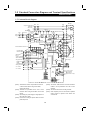
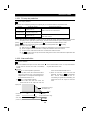
1.6.7 Reset Signal (Terminal RES)
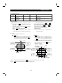
Used to reset the alarm stop state established by the
Operation is enabled within 0.2 seconds after the terminals
protective function of the inverter activated. The reset
RES and SD are disconnected.
signal immediately sets the control circuit to the initial
The reset terminal is used to reset the inverter alarm stop
(cold) state, e.g. initializes the electronic thermal relay and
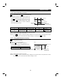
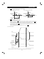
state. If the reset terminal is connected, then disconnected
built-in brake resistor overheat protection circuit. It shuts
while the inverter is operating, the motor may be restarted
off the inverter output at the same time. During reset, the
during coasting (refer to the following timing chart) and the
inverter output is kept shut off. To give this reset input,
output may be shut off by overvoltage.
connect terminals RES and SD for more than 0.1 second.
Note that frequent resetting will make the electronic
When the connection time is long, the PU displays the
thermal relay and brake resistor overheat protection
initial screen, which is not a fault.
invalid.
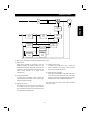
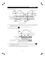
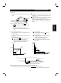
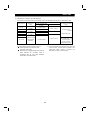
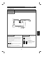
Motor speed
There is strong
possibility of inverter
output shut-off if
motor is restarted
during coasting.
Coasting
Coasting time
ON
Across RES-SD
Coasting to stop
(Indicates motor speed)
ON
ON
Across STF (STR)-SD
Approximately 0.2s
Approximately 0.2s
T
T: Must be greater than the time
required for coasting to stop.
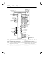
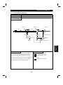
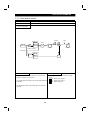
Reset Input Timing Chart During Normal Operation
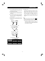
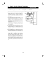
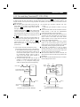
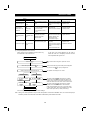
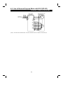
1.6.8 External Transistor Common (Terminal PC)
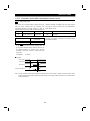
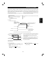
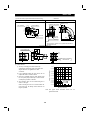
When the transistor output (open collector) of a
Inverter
PC
programmable controller (PC) having an external power
supply is input to the inverter, supply external interface
PC
DC12/24V
power to prevent a fault from occurring due to leakage
Photo-coupler
currents as shown below.
By connecting as shown in the right figure, the external
power is supplied to the photocoupler in the inverter as
Y00
Photocoupler
STF
indicated by the dotted lines. Since terminal SD is not
External
power
supply
connected, no power is supplied to the photocoupler from
the control power supply of the inverter.
Inverter control
power supply
SD
0V
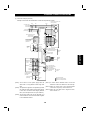
Terminal PC Connection Example
25