1
• Features
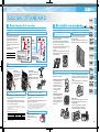
Highly reliable inverter!
(1)
Compact yet equipped with highest level of function/performance!!
Safety stop function
The FR-D700 series is compliant to the EU
Machinery Directive without the addition of
previously required external devices.
Operation of an external Emergency
Stop device results in a highly reliable
immediate shutoff of the D700's output to
the motor.
This safety stop function conforms to the
following standards.
(1)
Provided by the user (present)
Emergency stop
FR-D700
Safety function
is equipped
•Magnetic contactor (MC)
•Emergency stop wiring
For conventional model...
model
Two MCs were necessary
EN954-1 Category 3
IEC60204-1 Stop Category 0
*
Emergency stop
Only one MC is enough
with safety stop function!
¥High cost
¥Maintenance of two MCs was
necessary
¥Installation space was necessary
¥Cost reduction
¥Maintenance of one MC
¥Installation space is reduced
150%/1Hz high starting torque by General
-purpose magnetic flux vector control
General-purpose magnetic flux vector control and auto
tuning function are available.
It ensures operation that requires high starting torque,
such as transfer machine including conveyer, hoist, lift,
etc., washing machine, and agitators.
•High torque 150%/1Hz and 200%/3Hz (3.7K or less) are
achieved with slip compensation function.
•Auto tuning
Many kinds of motors can be optimally controlled with
Mitsubishi original "non-rotation " auto tuning function.
(R1 constants tuning)
(2)
Brake resistor can be connected
A brake transistor is built-in to the 0.4K or more.
Connecting an optional brake resistor increases
regeneration capability.
It is useful for deceleration time reduction of a machine
with a large inertia, such as fan, and operation of lift, etc.
(example: conveyer)
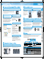
*: Main circuit terminal is screw terminal.
by inserting wires treated
with bar terminal (max.
diameter 1.5mm)
Capable of wiring without
a bar terminal.
(3)
section inside prevents contact fault
by vibration.
is unnecessary
•Maintenance
Screw retightening is unnecessary.
(3)
Long-life design
(4)
•The design life of the cooling fan has been extended to 10
•Degrees of deterioration of main circuit capacitor, control
years*1. The life of the fan can be further extended utilizing the
it’s ON/OFF control.
•The design life of the capacitors has been extended to 10
years by the adoption of a capacitor endures 5000 hours at
105˚C surrounding air temperature*1,*2.
circuit capacitor, and inrush current limit circuit can be
monitored.
•Trouble can be avoided with the self-diagnostic alarm*4 that is
output when the life span is near.
*1: Surrounding air temperature : annual average 40˚C (free from corrosive gas,
flammable gas, oil mist, dust and dirt) Since the design life is a calculated value, it is
not a guaranteed value.
*2: Output current : 80% of the inverter rated current
(5)
•Life indication of critical components
Components
Guideline of the FR-D700 Life
10 years
Cooling fan
10 years
Main circuit smoothing capacitor
10 years
Printed board smoothing capacitor
1
*4: If any one of main circuit capacitor, control circuit capacitor, inrush current restriction
circuit or cooling fan reaches the output level, an alarm is output. Capacity of the main
circuit capacitor can be measured by setting parameter at a stop and turning the
power from off to on. Measuring the capacity enables alarm to be output.
The cooling fan outputs alarm by using fan speed detection.
Guideline of JEMA*3
2 to 3 years
5 years
5 years
*3: Excerpts from "Periodic check of the transistorized inverter" of JEMA (Japan Electrical
Manufacture's Association)
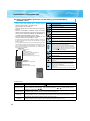
• Option and peripheral devices 24
Enhanced function
(example: hoist)
Leading life check function
• Terminal connection
diagram
11
• Terminal specification
explanation
(example: automated storage)
(example:
industrial washing machine)
New functions and useful functions from superior models
support all sorts of applications.
(example: automobile production line)
7
• Protective 23
functions
With spring terminals, the wiring became easier and more secure.
reliable
•Highly
Spring structure in terminal contact
• Outline dimension drawings
• Parameter list 16
Spring clamp terminal (control circuit terminal)
wiring
•Easy
Wiring is completed only
• Standard 5
specifications
• Operation panel 13
• Parameter unit
*: Approved safety relay unit
(2)
1
• For a pressing machine and
Regeneration avoidance function
fan rotated faster than the set
speed due to the effect of
another fan, a trip is less likely
to occur by automatically
increasing frequency at
regeneration.
excitation control
•Optimum
This control enables the motor
efficiency to its optimum. More
energy saving is possible in
applications with variable load
torque characteristic such as
fan and pump.
failure-time deceleration-to-stop function
•Power
The motor can be decelerated to a stop when a power
failure or undervoltage occur to prevent the motor from
coasting.
For fail-safe of machine tool, etc., it is effective to stop
the motor when a power failure occurs.
• Precautions for operation/selection 27
• Precautions for peripheral device selection
• FR-D700 Series
Specification 32
Difference List
• Warranty
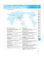
• International
FA Center
(example: pressing machine)
33
(example: spindle)
• Entering position detection signal of dancer roll to use
Dancer control
PID control enables tension control by dancer roll.
• Traverse function for wind-up drum of spinning
Traverse function
(example: air-conditioning fan)
machine and wiredrawing machine prevents
unevenness and deformation at thread winding.
Password function
Registering 4-digit password can limit
parameter read/write.
It is effective for parameter setting
protection.
(example: pump)
(example: textile machine)
(example: wiredrawing machine)
2
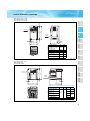
The operation panel of the inverter can not be removed.
A parameter unit connection cable (FR-CB20 ) is
separately necessary.
Parameter unit FR-PU07 (option)
An optional parameter unit (FR-PU07) can be connected as well.
A parameter unit connection cable (FR-CB20
) is separately necessary.
•Setting such as direct input method with a numeric
keypad, operation status indication, and help
function are usable.
Eight languages can be displayed.
•Parameter setting values of maximum of three
inverters can be stored.
•A battery pack type (FR-PU07BB(-L)) allows
parameter setting and parameter copy without
powering on the inverter. (available soon)
Acceleration/deceleration
pattern setting
Acceleration/deceleration
time setting
Features
Outline
Dimension
Drawings
Optional enclosure surface operation panel (FR-PA07) can be
connected. In addition, an operation panel for the FR-E500
series can be connected.
(4)
Setting wizard function (example: acceleration/deceleration time setting)
Enclosure surface operation panel
FR-PA07 (option)
Terminal Connection
Diagram
Terminal Specification
Explanation
Connecting a personal computer and the inverter via RS-485
communication enables setting with wizard (interactive)
function of the FR Configurator (inverter setup software).
In addition, a parameter setting can be converted from the FRS500 series to the FR-D700 series by "Convert" function.
"Graph" function displays monitor data in waveform.
(3)
Since a cover can be fitted
after wiring, wiring work is
easily done.
(1)
RoHS Directive compliant
Human and environment-friendly inverter in compliant with
RoHS Directive.
Compliance to the EMC Directive of European Norm is easier.
•EMC filter integrated type will be added to the line (to be released).
•Noise filter option which is compatible with EMC Directive
RoHS Directive requires member nations to guarantee that new electrical and electronic
equipment sold in the market after July 1, 2006 do not contain lead, cadmium, mercury,
hexavalent chromium, polybrominated biphenyl (PBB) and polybrominated diphenyl ether
(PBDE) flame retardants.
<G> mark indicating RoHS Directive compliance is printed on the package.
(2)
EMC Directive compliant noise filter
(3)
(EN61800-3 2nd Environment Category C3) is available.
Complies with UL, cUL,EN (LVD) standards
(4)
Protective
Functions
Easy setting from
a personal computer using
the FR Configurator (option)
A cooling fan is provided on top
of the inverter of all capacities
requiring a cooling fan (1.5K or
more).
A cooling fan can be easily
replaced without disconnecting
main circuit wires.
Filter pack FR-BFP2 (option)
Power factor improving DC reactor, zero phase reactor, and
capacitative filter (radio noise filter), are frequently-used units
for an air conditioning application. The filter pack combines
those three units are available as an option.
Options
(2)
Combed shaped wiring cover
(2)
Operation panel
Parameter unit
Setting dial is the feature of Mitsubishi inverters.
•Displayed numbers can be jumped by turning the setting dial quickly, and numbers
can be changed one by one by turning it slowly, enabling speedy parameter setting.
•The nonslip setting dial is easier to turn.
Easy replacement of cooling fan
Standard
Specifications
(1)
Parameter
List
Quick setup with the setting dial
To use a parameter unit with battery pack (FR-PU07BB) outside Japan,
order a “FR-PU07BB-L” (parameter unit type indicated on the package
has L at the end).
Instructions
(1)
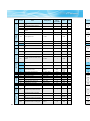
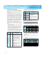
The lineup of three phase 200V/400V class goes to 15K.
inverter protocol and Modbus-RTU
•Mitsubishi
Communication speed of RS-485 has been improved
•For a use in harsh environment, special unit with board coating is also available. Please contact our sales representative.
•For the FR-D700 series, North American (NA), EU (EC), and Chinese (CHT) specifications also are supported.
*: This catalog explains based on the Japanese specifications.
Consult our sales office for specifications of each country.
(communication at 38.4kbps is available)
"Multi command mode" has been added to Mitsubishi inverter protocol
(data processing time of the inverter has been reduced to 1/4)
Supports Modbus RTU
(1)
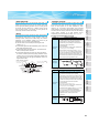
Easily replaceable compact body
Installation size is the same as that of the FR-S500 series which
is the smallest model of the Mitsubishi inverter.
(2)
F R-D 740
Symbol
1
2
4
Side by side installation saves space
Space can be saved by side by side no clearance installation*.
*: Use the inverter at the surrounding air temperature of 40˚C or less.
Power
Supply
Voltage
100V class
200V class
400V class
Inverter Type
Three phase
200V
Three phase
400V
128mm
Single phase
200V *
Single phase
100V *
3
FR-D740-0.4K
FR-S540E-0.4K
FR-D700 Series
Specification
Difference List
Parameter list display
Enhanced communication function
Symbol
None
S
W
-0. 4K -
Number of Power Phases
Three-phase input
Single-phase input
Single-phase input
(double voltage output)
Inverter Capacity
0.1
0.2
Symbol
Warranty
International
FA Center
(5)
Inverter Capacity
Indicate capacity
0.1K to 15K
"kW".
0.4
0.75
1.5
2.2
Symbol
None
C
3.7
5.5
Protective Structure
Enclosed-type structure IP20
Totally enclosed structure IP40
7.5
11
15
Enclosed structure (IP20)
FR-D720- K
FR-D740- K
Totally-enclosed structure (IP40)
Enclosed structure (IP20)
Totally-enclosed structure (IP40)
FR-D720S- K
Enclosed structure (IP20)
FR-D710W- K
Enclosed structure (IP20)
*: Output of the single-phase 200V and single-phase 100V input models is three-phase 200V.
:Available models
:Models to be released
:Not available
4
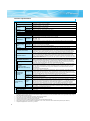
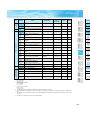
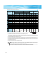
Standard specifications
Rating
z Three-phase 200V power supply
Model FR-D720-
K(-C)∗6
Model FR-D720-
-NA
0.1
008
0.2
014
0.4
025
0.75
042
1.5
070
2.2
100
3.7
165
5.5
238
7.5
318
0.1
0.2
0.4
0.75
1.5
2.2
3.7
5.5
7.5
Rated capacity (kVA)∗2
0.3
0.6
1.0
1.7
2.8
4.0
6.6
9.5
12.7
Rated current (A)
0.8
1.4
2.5
4.2
7.0
10.0
16.5
23.8
31.8
12.0
17.0
Output
Applicable motor capacity (kW)∗1
Overload current rating∗3
150% 60s, 200% 0.5s (inverse-time characteristics)
Power supply
Voltage∗4
Three-phase 200 to 240V
Rated input AC voltage/frequency
Three-phase 200 to 240V 50Hz/60Hz
Permissible AC voltage fluctuation
170 to 264V 50Hz/60Hz
Permissible frequency fluctuation
±5%
Power supply capacity (kVA)∗5
0.4
0.7
Protective structure (JEM1030)
2.1
4.0
5.5
9.0
Enclosed type (IP20). IP40 for totally enclosed structure series.
Cooling system
Approximate mass (kg)
1.2
Self-cooling
Forced air cooling
0.5
0.5
0.8
1.0
1.4
1.4
1.8
0.4
012
012
0.4
0.75
022
022
0.75
1.5
036
036
1.5
2.2
050
050
2.2
3.7
080
080
3.7
5.5
120
120
5.5
7.5
160
160
7.5
Applicable motor capacity (kW)∗1
0.4
0.75
1.5
2.2
3.7
5.5
7.5
Rated capacity (kVA)∗2
0.9
1.7
2.7
3.8
6.1
9.1
12.2
Rated current (A)
1.2
2.2
3.6
5.0
8.0
12.0
16.0
3.6
3.6
z Three-phase 400V power supply
Output
Model FR-D740-
K(-C)∗6
Model FR-D740-
-NA
Model FR-D740-
-EC
Model FR-D740-
K-CHT
Overload current rating∗3
150% 60s, 200% 0.5s (inverse-time characteristics)
Power supply
Voltage∗4
Three-phase 380 to 480V
Rated input AC voltage/frequency
Three-phase 380 to 480V 50Hz/60Hz
Permissible AC voltage fluctuation
325 to 528V 50Hz/60Hz
Permissible frequency fluctuation
±5%
Power supply capacity (kVA)∗5
Protective structure (JEM1030)
Cooling system
Approximate mass (kg)
1.5
2.5
4.5
5.5
9.5
12.0
17.0
Enclosed type (IP20). IP40 for totally enclosed structure series.
Self-cooling
1.3
1.3
Forced air cooling
1.4
1.5
1.5
3.3
3.3
∗1
The applicable motor capacity indicated is the maximum capacity applicable for use of the Mitsubishi 4-pole standard motor.
∗2
The rated output capacity indicated assumes that the output voltage is 230V for three-phase 200V class and 440V for three-phase 400V class.
∗3
The % value of the overload current rating indicated is the ratio of the overload current to the inverter's rated output current. For repeated duty, allow time for
the inverter and motor to return to or below the temperatures under 100% load.
∗4
The maximum output voltage does not exceed the power supply voltage. The maximum output voltage can be changed within the setting range. However,
the pulse voltage value of the inverter output side voltage remains unchanged at about 2 that of the power supply.
5
∗5
The power supply capacity varies with the value of the power supply side inverter impedance (including those of the input reactor and cables).
∗6
Totally enclosed structure series ends with -C.
0.75
042
042
0.75
1.5
070
070
1.5
2.2
100
100
2.2
Applicable motor capacity (kW)∗1
0.1
0.2
0.4
0.75
1.5
2.2
Rated capacity (kVA)∗2
0.3
0.6
1.0
1.7
2.8
4.0
Rated current (A)
0.8
1.4
2.5
4.2
7.0
10.0
150% 60s, 200% 0.5s (inverse-time characteristics)
Three-phase 200 to 240V
Rated input AC voltage/frequency
Single-phase 200 to 240V 50Hz/60Hz
Permissible AC voltage fluctuation
170 to 264V 50Hz/60Hz
Permissible frequency fluctuation
±5%
Protective structure (JEM1030)
2.3
4.0
5.2
Enclosed type (IP20).
Cooling system
Approximate mass (kg)
1.5
Self-cooling
0.5
Forced air cooling
0.5
0.9
1.1
1.5
2.0
z Single-phase 100V power supply
0.1
008
0.2
014
0.4
025
0.75
042
Applicable motor capacity (kW)∗1
0.1
0.2
0.4
0.75
Rated capacity (kVA)∗2
0.3
0.6
1.0
1.7
Rated current (A)
0.8
1.4
2.5
4.2
Overload current rating∗3
Voltage
Power supply
150% 60s, 200% 0.5s
(inverse-time characteristics)
Three-phase 200 to 230V∗6, ∗7
Rated input AC voltage/frequency
Single-phase 100 to 115V 50Hz/60Hz
Permissible AC voltage fluctuation
90 to 132V 50Hz/60Hz
Permissible frequency fluctuation
±5%
Power supply capacity (kVA)∗5
0.5
Protective structure (JEM1030)
1.5
2.5
Enclosed type (IP20).
Cooling system
Approximate mass (kg)
0.9
Options
Output
Model FR-D710W-
K
Model FR-D710W-
-NA
Operation panel
Parameter unit
0.9
Parameter
List
0.5
Instructions
Power supply capacity (kVA)∗5
Self-cooling
0.6
0.7
0.9
1.4
∗1
The applicable motor capacity indicated is the maximum capacity applicable for use of the Mitsubishi 4-pole standard motor.
∗2
The rated output capacity indicated assumes that the output voltage is 230V.
∗3
The % value of the overload current rating indicated is the ratio of the overload current to the inverter's rated output current. For repeated duty, allow time for
the inverter and motor to return to or below the temperatures under 100% load. If the automatic restart after instantaneous power failure function (Pr. 57) or
FR-D700 Series
Specification
Difference List
Power supply
Voltage∗4
Protective
Functions
Overload current rating∗3
Standard
Specifications
0.4
025
025
0.4
Outline
Dimension
Drawings
0.2
014
014
0.2
Terminal Connection
Diagram
Terminal Specification
Explanation
0.1
008
008
0.1
Output
Model FR-D720S-
K
Model FR-D720S-
-NA
Model FR-D720S-
-EC
Model FR-D720S-
K-CHT
Features
z Single-phase 200V power supply
level and load of 100% or more may not be available.
∗4
The maximum output voltage does not exceed the power supply voltage. The maximum output voltage can be changed within the setting range. However,
the pulse voltage value of the inverter output side voltage remains unchanged at about 2 that of the power supply.
∗5
The power supply capacity varies with the value of the power supply side inverter impedance (including those of the input reactor and cables).
∗6
For single-phase 100V power input model, the maximum output voltage is twice the amount of the power supply voltage and cannot be exceeded.
∗7
In a single-phase 100V power input model, the output voltage may fall down when the load is heavy, and larger output current may flow compared to a three-
Warranty
International
FA Center
power failure stop function (Pr. 261) is set and power supply voltage is low while load becomes bigger, the bus voltage decreases to power failure detection
phase input model. Use the motor with less load so that the output current is within the rated motor current range.
6
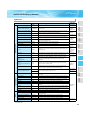
Common specifications
Soft-PWM control/high carrier frequency PWM control (V/F control, General-purpose magnetic flux vector control,
and Optimum excitation control are available)
0.2 to 400Hz
Output frequency range
0.06Hz/60Hz (terminal2, 4: 0 to 10V/10bit)
0.12Hz/60Hz (terminal2, 4: 0 to 5V/9bit)
Frequency setting Analog input
0.06Hz/60Hz (terminal4: 0 to 20mA/10bit)
resolution
0.01Hz
Digital input
Within ±1% of the max. output frequency (25°C ±10°C)
Analog input
Frequency
accuracy
Within 0.01% of the set output frequency
Digital input
Base frequency can be set from 0 to 400Hz. Constant-torque/variable torque pattern can be selected
Voltage/frequency characteristics
150% or more (at 1Hz)...when General-purpose magnetic flux vector control and slip compensation is set
Starting torque
Manual torque boost
Torque boost
0.1 to 3600s (acceleration and deceleration can be set individually),
Acceleration/deceleration time setting
Linear and S-pattern acceleration/deceleration modes are available.
0.1K, 0.2K ... 150%,
0.4K, 0.75K ... 100%,
Regenerative∗1
1.5K ... 50%,
Braking torque
2.2K or more ... 20%
DC injection brake Operation frequency (0 to 120Hz), operation time (0 to 10s), and operation voltage (0 to 30%) can be changed
Operation current level (0 to 200%), and whether to use the function or not can be selected
Stall prevention operation level
Two terminals
Terminal 2: 0 to 10V and 0 to 5V are available
Frequency setting Analog input
Terminal 4: 0 to 10V, 0 to 5V, and 4 to 20mA are available
signal
Digital input and frequency setting increments can be entered from operation panel or parameter unit.
Digital input
Forward and reverse rotation or start signal automatic self-holding input (3-wire input) can be selected.
Start signal
Following signals can be assigned to Pr. 178 to Pr.182 (input terminal function selection): multi-speed selection, remote
setting, second function selection, terminal 4 input selection, JOG operation selection, PID control valid terminal,
external thermal input, PU-External operation switchover, V/F switchover, output stop, start self-holding selection,
Input signal (five terminals)
forward rotation, reverse rotation command, inverter reset, PU-NET operation switchover, External-NET operation
switchover, command source switchover, inverter operation enable signal, and PU operation external interlock.
Maximum/minimum frequency setting, frequency jump operation, external thermal relay input selection, automatic
restart after instantaneous power failure operation, forward/reverse rotation prevention, remote setting, second
function, multi-speed operation, regeneration avoidance, slip compensation, operation mode selection, offline auto
Operational functions
tuning function, PID control, computer link operation (RS-485), Optimum excitation control, power failure stop, speed
smoothing control, Modbus-RTU
Following signals can be assigned to Pr.190 and Pr.192 (output terminal function selection): inverter operation, up-toOutput signal
Open collector output (one terminal) frequency, overload alarm, output frequency detection, regenerative brake prealarm, electronic thermal relay function
prealarm, inverter operation ready, output current detection, zero current detection, PID lower limit, PID upper limit,
Relay output (one terminal)
PID forward/reverse rotation output, fan alarm∗2, heatsink overheat pre-alarm, deceleration at an instantaneous
power failure, PID control activated, PID output interruption, during retry, life alarm, current average value monitor,
Operating status
remote output, alarm output, fault output, fault output 3, and maintenance timer alarm.
Following signals can be assigned to Pr.54 FM terminal function selection: output frequency, output current (steady),
output voltage, frequency setting, converter output voltage, regenerative brake duty, electronic thermal relay function
For meter
load factor, output current peak value, converter output voltage peak value, reference voltage output, motor load
Pulse train output
factor, PID set point, PID measured value, output power, PID deviation, motor thermal load factor, and inverter
(MAX 2.4kHz: one terminal)
thermal load factor.
Pulse train output (1440 pulses/s/full scale)
Following operating status can be displayed: output frequency, output current (steady), output voltage, frequency
setting, cumulative energization time, actual operation time, converter output voltage, regenerative brake duty,
Operating status electronic thermal relay function load factor, output current peak value, converter output voltage peak value, motor
Operation panel
load factor, PID set point, PID measured value, PID deviation, inverter I/O terminal monitor, output power, cumulative
power, motor thermal load factor, inverter thermal load factor, and PTC thermistor resistance.
Parameter unit
Fault definition is displayed when a fault occurs. Past 8 fault definitions (output voltage/current/frequency/cumulative
Fault definition
(FR-PU07)
energization time right before the fault occurs) are stored.
Indication
Operation specifications
Control specifications
Control method
Interactive
guidance
Function (help) for operation guide ∗3
Environment
Overcurrent during acceleration, overcurrent during constant speed, overcurrent during deceleration, overvoltage
during acceleration, overvoltage during constant speed, overvoltage during deceleration, inverter protection thermal
Protective
operation, motor protection thermal operation, heatsink overheat, input phase loss ∗4 ∗5, output side earth (ground)
fault overcurrent at start∗4, output phase loss, external thermal relay operation ∗4, PTC thermistor operation∗4,
function
Protective/warning
parameter error, PU disconnection, retry count excess ∗4, CPU fault, brake transistor alarm, inrush resistance
function
overheat, analog input error, stall prevention operation, output current detection value exceeded ∗4, safety circuit fault
Fan alarm∗2, overcurrent stall prevention, overvoltage stall prevention, PU stop, parameter write error, regenerative
Warning
brake prealarm ∗4, electronic thermal relay function prealarm, maintenance output ∗4, undervoltage, operation panel
function
lock, password locked, inverter reset, safety stop
-10°C to +50°C maximum (non-freezing) (-10°C to +40°C for totally-enclosed structure feature) ∗6
Surrounding air temperature
90%RH or less (non-condensing)
Ambient humidity
-20°C to +65°C
Storage temperature∗7
Indoors (without corrosive gas, flammable gas, oil mist, dust and dirt etc.)
Atmosphere
Maximum 1000m above sea level, 5.9m/s 2 or less at 10 to 55Hz (directions of X, Y, Z axes)
Altitude/vibration
∗1 The braking torque indicated is a short-duration average torque (which varies with motor loss) when the motor alone is decelerated from 60Hz in the
shortest time and is not a continuous regenerative torque. When the motor is decelerated from the frequency higher than the base frequency, the average
deceleration torque will reduce. Since the inverter does not contain a brake resistor, use the optional brake resistor when regenerative energy is large. A
brake unit (FR-BU2) may also be used.
∗2 As the 0.75K or less are not provided with the cooling fan, this alarm does not function.
∗3 This operation guide is only available with option parameter unit (FR-PU07).
∗4 This protective function does not function in the initial status.
∗5 This protective function is available with the three-phase power input specification model only.
∗6 When using the inverters at the surrounding air temperature of 40°C or less, the inverters can be installed closely attached (0cm clearance).
∗7 Temperatures applicable for a short time, e.g. in transit.
7
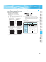
Outline Dimension Drawings
Standard
Specifications
5
Features
zFR-D720-0.1K to 0.75K
zFR-D720S-0.1K to 0.75K
zFR-D710W-0.1K to 0.4K
Outline
Dimension
Drawings
Terminal Connection
Diagram
Terminal Specification
Explanation
Rating
plate
4
5
5
56
D1
D
FR-D720-0.1K, 0.2K
FR-D720S-0.1K, 0.2K
FR-D710W-0.1K
D
D1
80.5
10
FR-D710W-0.2K
110.5
10
FR-D720-0.4K
112.5
42
FR-D720-0.75K
132.5
62
FR-D720S-0.4K
FR-D710W-0.4K
142.5
42
FR-D720S-0.75K
162.5
62
Parameter
List
Inverter Type
Operation panel
Parameter unit
68
(Unit: mm)
Protective
Functions
118
128
1-φ5 hole
Instructions
5
Options
zFR-D720-1.5K to 3.7K
zFR-D740-0.4K to 3.7K
zFR-D720S-1.5K
zFR-D710W-0.75K
FAN *
FR-D700 Series
Specification
Difference List
128
118
2-φ5 hole
5
5
5
Warranty
International
FA Center
Rating
plate
W1
D1
W
D
∗ FR-D740-0.4K, 0.75K, FR-D710W-0.75K are not provided with the cooling fan.
Inverter Type
W
W1
FR-D720-1.5K, 2.2K
FR-D740-1.5K
FR-D740-0.4K, 0.75K
FR-D740-2.2K
FR-D720S-1.5K
108
96
FR-D740-3.7K
D1
135.5
60
129.5
54
155.5
60
165.5
FR-D710W-0.75K
FR-D720-3.7K
D
170
158
149.5
54
142.5
66.5
(Unit: mm)
8
6
zFR-D720S-2.2K
FAN
150
138
2-φ5 hole
Rating
plate
5
6
5
128
60
145
140
(Unit: mm)
6
zFR-D720-5.5K, 7.5K
zFR-D740-5.5K, 7.5K
FAN
150
138
2-φ5 hole
Rating
plate
10
6
5
208
220
68
155
(Unit: mm)
9
zParameter unit (option) (FR-PU07)
<Panel cut dimension drawing>
Features
<Outline drawing>
25.05
(11.45)
*1
40
40
Standard
Specifications
(14.2)
2.5
83
Air-bleeding
hole
51
50
*1
4-R1
26.5
4-φ4 hole
(Effective depth of the
installation screw hole 5.0)
M3 screw *2
Operation panel
Parameter unit
26.5
Terminal Connection
Diagram
Terminal Specification
Explanation
57.8
67
56.8
135
Outline
Dimension
Drawings
*1
*1
When installing the FR-PU07 on the enclosure, etc., remove screws or fix the screws to the FR-PU07 with M3 nuts.
Select the installation screw whose length will not exceed the effective depth of the installation screw hole.
(Unit: mm)
zParameter unit with battery pack (option) (FR-PU07BB (-L))
Parameter
List
80.3
∗1
∗2
<Outline drawing>
8.2
46.7
Protective
Functions
83
46.7
44.7
(Unit: mm)
zEnclosure surface operation panel (option) (FR-PA07)
<Outline drawing>
Warranty
International
FA Center
FR-D700 Series
Specification
Difference List
Instructions
135
Options
6
18
<Panel cut dimension drawing>
22
68
36
45
11
20
22
59
15.5
24
2-M3 screw
(Unit: mm)
10
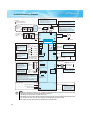
Terminal Connection Diagram
*1. DC reactor (FR-HEL)
When connecting a DC reactor, remove the
jumper across P1 and P/+
Single-phase 100V power input model is not
compatible with DC reactor.
Sink logic
Main circuit terminal
Control circuit terminal
Single-phase power input
MCCB
*7 A brake transistor is not built-in to the
0.1K and 0.2K.
Brake unit
(Option)
MC
Single-phase
AC power
supply
R/L1
S/L2
*1
*8
PR N/*7
P/+
P1
*6
MC
R/L1
S/L2
T/L3
Three-phase
AC power
supply
*8 Brake resistor (FR-ABR, MRS type, MYS
type)
Install a thermal relay to prevent an
overheat and burnout of the brake resistor.
(The brake resistor can not be connected
to the 0.1K and 0.2K.)
R
Earth
(Ground)
Jumper
MCCB
*6 Terminal P1 is not available for singlephase 100V power input model.
Earth
(Ground)
Motor
U
V
W
IM
Main circuit
Earth (Ground)
Control circuit
supply, take care not to
short across terminals
PC and SD.
Contact input common
24VDC power supply
Relay output
C
STF
B
STR
RM
SD
Open collector output
RUN
SINK
RL
Running
Frequency setting signals (Analog)
*4 It is recommended to
use 2W1kΩ when the
frequency setting signal
is changed frequently.
3
Frequency
setting
potentiometer
1/2W1kΩ
*4
1
Calibration resistor
10(+5V)
+
2 0 to 5VDC *3
(0 to 10VDC)
2
4 4 to 20mADC
0 to 5VDC
0 to 10VDC *5
*5 Terminal input specifications can be changed by analog
input specifications switchover (Pr. 267). Set the
voltage/current input switch in the "V" position to select
voltage input (0 to 5V/0 to10V) and "I" (initial value) to
select current input (4 to 20mA).
To use terminal 4 (initial setting is current input), set "4"
in any of Pr.178 to Pr.182 (input terminal function
selection) to assign the function, and turn ON AU signal.
Safety stop signal
Safe stop input (Line 1)
Safe stop input (Line 2)
Common terminal
Shorting
wire
V
-
SD
PU
connector
Indicator
(Frequency meter, etc.)
Moving-coil type
1mA full-scale
FM
5(Analog common)
Terminal 4
(+)
input
(Current (-)
input)
Terminal functions vary by
Pr. 190 RUN terminal function
selection
Open collector output common
Sink/source common
SE
PC *2
(Common for external power supply transistor)
*3 Terminal input specifications
can be changed by analog
input specifications
switchover (Pr. 73).
Terminal 10 and terminal 2
are used as PTC input
terminal (Pr. 561).
Terminal functions vary
by Pr. 192 A,B,C terminal
function selection
Relay output
(Fault output)
A
RH
SOURCE
Control input signals (No voltage input allowed)
Forward
Terminal functions vary rotation start
with the input terminal Reverse
assignment (Pr. 178 to rotation start
Pr. 182)
High
speed
Multi-speed selection Middle
speed
*2 When using terminals PCLow
SD as a 24VDC power
speed
*9
*9 It is not necessary when
calibrating the indicator
from the operation panel.
I
Voltage/current
input switch *5
S1
SO
S2
SC
Safety monitor output *10
*10 Common terminal of
terminal SO is terminal SC.
(Connected to terminal SD
inside of the inverter.)
Note
y To prevent a malfunction caused by noise, separate the signal cables more than 10cm from the power cables. Also
separate the main circuit wire of the input side and the output side.
y After wiring, wire offcuts must not be left in the inverter.
Wire offcuts can cause an alarm, failure or malfunction. Always keep the inverter clean. When drilling mounting holes
in an enclosure etc., take care not to allow chips and other foreign matter to enter the inverter.
y The output of the single-phase power input specification is three-phase 200V.
11
Terminal Specification Explanation
Contact input
STF
Forward rotation start
STR
RH, RM, RL
Reverse rotation start
SD
PC
10
Frequency setting
Control circuit/input signal
Earth (Ground)
2
4
PTC
Control circuit/output signal
Safety stop signal
Communication
Pulse Open collector Relay thermistor
5
Multi-speed selection
Contact input common
(sink) (initial setting)
A, B, C
Relay output (fault output)
RUN
Inverter running
FM
—
S1
S2
SO
SC
Turn on the STF signal to start forward rotation and turn it off to stop. When the STF and STR signals
are turned on simultaneously,
Turn on the STR signal to start reverse rotation and turn it off to stop. the stop command is given.
Multi-speed can be selected according to the combination of RH, RM and RL signals.
Common terminal for contact input terminal (sink logic) and terminal FM.
When connecting the transistor output (open collector output), such as a programmable controller,
when source logic is selected, connect the external power supply common for transistor output to this
terminal to prevent a malfunction caused by undesirable currents.
Common output terminal for 24VDC 0.1A power supply (PC terminal).
24VDC power supply common
Isolated from terminals 5 and SE.
When connecting the transistor output (open collector output), such as a programmable controller,
External transistor common
when sink logic is selected, connect the external power supply common for transistor output to this
(sink) (initial setting)
terminal to prevent a malfunction caused by undesirable currents.
Contact input common (source) Common terminal for contact input terminal (source logic).
24VDC power supply
Can be used as 24VDC 0.1A power supply.
5VDC
Frequency setting power
Used as power supply when connecting potentiometer for frequency setting
permissible load
supply
(speed setting) from outside of the inverter.
current 10mA
Inputting 0 to 5VDC (or 0 to 10V) provides the maximum output
Input resistance 10kΩ ± 1kΩ
frequency at 5V (10V) and makes input and output proportional.
Frequency setting (voltage)
Permissible maximum voltage
Use Pr. 73 to switch between input 0 to 5VDC (initial setting) and 0
20VDC
to 10VDC input.
Inputting 0 to 20mADC (or 0 to 5V / 0 to 10V) provides the
Voltage input:
maximum output frequency at 20mA makes input and output
Input resistance 10kΩ ± 1kΩ
proportional. This input signal is valid only when the AU signal is
Permissible maximum voltage
Frequency setting (current) on (terminal 2 input is invalid). Use Pr. 267 to switch from among
20VDC
input 4 to 20mA (initial setting), 0 to 5VDC and 0 to 10VDC. Set the Current input:
voltage/current input switch in the "V" position to select voltage
Input resistance 233Ω ± 5Ω
Maximum permissible current 30mA.
input (0 to 5V/0 to 10V).
Frequency setting common Common terminal for the frequency setting signals (terminals 2 or 4). Do not earth (ground).
PTC thermistor input
SE
For connecting PTC thermistor output.
Adaptive PTC thermistor
When PTC thermistor protection is valid (Pr. 561 ≠ "9999"), terminal resistance:
2 is not available for frequency setting.
500Ω to 30kΩ
1 changeover contact output indicates that the inverter fault occurs.
Fault: discontinuity across B-C (continuity across A-C), Normal: continuity across B-C (discontinuity
across A-C) Contact capacity 230VAC 0.3A (power factor = 0.4) 30VDC 0.3A
Switched low when the inverter output frequency is equal to or
Permissible load 24VDC
higher than the starting frequency (initial value 0.5Hz). Switched
(Maximum 27VDC) 0.1A
high during stop or DC injection brake operation.
(a voltage drop is 3.4V maximum
(Low is when the open collector output transistor is ON (conducts).
when the signal is on)
High is when the transistor is OFF (does not conduct).)
Open collector output common Common terminal of terminal RUN and FU.
For meter
PU connector
Features
For earthing (grounding) the inverter chassis. Must be earthed (grounded).
External transistor common
(source)
10
2
Standard
Specifications
DC reactor connection
Outline
Dimension
Drawings
P/+, P1 ∗
Terminal Connection
Diagram
Terminal Specification
Explanation
Brake unit connection
Operation panel
Parameter unit
P/+, N/-
Parameter
List
Inverter output
Brake resistor connection
Protective
Functions
U, V, W
P/+, PR
Options
AC power input
Description
Connect to the commercial power supply. Keep these terminals open when using the high power
factor converter (FR-HC) or power regeneration common converter (FR-CV).
∗ When using single-phase power input, terminals are R/L1 and S/L2.
Connect a three-phase squirrel-cage motor.
Connect a brake resistor (FR-ABR, MRS type, MYS type) across terminals P/+ and PR.
(The brake resistor can not be connected to the 0.1K and 0.2K.)
Connect the brake unit (FR-BU2), power regeneration common converter (FR-CV) or high power
factor converter (FR-HC).
Remove the jumper across terminals P/+-P1 and connect a DC reactor.
Single-phase 100V power input model is not compatible with DC reactor.
∗ Terminal P1 is not available for single-phase 100V power input model.
Select one e.g. output frequency from monitor items. (Not output
during inverter reset.) The output signal is proportional to the
magnitude of the corresponding monitoring item.
Permissible load current 1mA
1440 pulses/s at 60Hz
With the PU connector, RS-485 communication can be made.
· Conforming standard: EIA-485 (RS-485)
· Transmission format: Multi-drop link
· Communication speed: 4800 to 38400bps
· Overall extension: 500m
Instructions
Main circuit
R/L1, S/L2,
T/L3 ∗
Terminal Name
FR-D700 Series
Specification
Difference List
Terminal
Symbol
Warranty
International
FA Center
Type
S1/S2 are safe stop signals for use with in conjunction with an approved external safety unit. Both S1/
S2 must be used in dual channel form. Inverter output is shutoff depending on shorting/opening
between S1 and SC, S2 and SC.
Safe stop input (Line 2)
Remove the shorting wire before using between S1, S2 and SC terminals.
This is a status signal for the safety related input signals.
Low indicates 'safe state' and high is 'drive enable or fault detected'. If high is indicated when both S1 and S2 are
Safety monitor output
open, refer to Safety stop function instruction manual (BCN-A211508-000) for diagnostics and repair action.
(open collector output)
(Low is when the open collector output transistor is ON (conducts). High is when the transistor is OFF
(does not conduct).)
Output shutoff terminal common Common terminal for terminals S1, S2 and SO. Connected to terminal SD inside of the inverter.
Safe stop input (Line 1)
Note
y Set Pr. 267 and a voltage/current input switch correctly, then input an analog signal in accordance with the setting. Applying
a voltage with voltage/current input switch in "I" position (current input is selected) or a current with switch in "V" position
(voltage input is selected) could cause component damage of the inverter or analog circuit of output devices.
y The inverter will be damaged if power is applied to the inverter output terminals (U, V, W). Never perform such wiring.
y
indicates that terminal functions can be selected using Pr. 178 to Pr. 182, Pr. 190, Pr. 192 (I/O terminal function selection).
y Terminal names and terminal functions are those of the factory set.
12
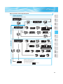
Explanation of the Operation Panel
The operation panel cannot be removed from the inverter.
Operation mode indication
PU: Lit to indicate PU operation mode.
EXT: Lit to indicate External operation mode.
(Lit at power-ON at initial setting.)
NET: Lit to indicate Network operation mode.
PU, EXT: Lit to indicate External/PU
combined operation mode 1, 2.
These turn OFF when command source is
not on operation panel.
Operating status display
Lit or flicker during inverter operation. ∗
∗ On: Indicates
that
forward
rotation
operation is being performed.
Slow flickering (1.4s cycle):
Reverse rotation operation
Fast flickering (0.2s cycle):
When
was pressed or the
start command was given, but the
Unit indication
Hz: Lit to indicate frequency.
(Flickers when the set frequency
monitor is displayed.)
A: Lit to indicate current.
(Both "Hz" and "A" turn off when other
than the above is displayed.)
Monitor (4-digit LED)
Shows the frequency, parameter number,
etc.
Setting dial
(Setting dial: Mitsubishi inverter dial)
Used to change the frequency setting
and parameter values.
Press to display the following.
y Displays the set frequency in the
monitor mode
y Present set value is displayed during
calibration
y Displays the order in the faults history
mode
Mode switchover
Used to change each setting mode.
Parameter setting mode indication
Lit to indicate parameter setting mode.
Monitor indication
Lit to indicate monitoring mode.
Stop operation
Used to stop Run command.
Fault can be reset when protective
function is activated (fault).
Operation mode switchover
Used to switch between the PU and
External operation mode.
When using the External operation mode
(operation using a separately connected
frequency setting potentiometer and start
signal), press this key to light up the EXT
indication.
(Press
simultaneously (0.5s) or
the operation mode.
Pressing for a while (2s) can lock
operation.
change Pr. 79 setting to change to combined
mode .)
PU: PU operation mode
EXT: External operation mode
Cancels PU stop also.
Determination of each setting
If pressed during operation, monitor
changes as below;
Start command
The rotation direction can be selected by
setting Pr. 40.
Pressing
simultaneously changes
Running frequency
Output current
Output voltage
13
operation can not be made.
yWhen the frequency command is less
than the starting frequency.
yWhen the MRS signal is input.
Features
Basic operation of the operation panel
Operation mode switchover
PU operation mode
(output frequency monitor)
Value change
and frequency flicker.
Frequency setting has been
written and completed!!
Output current monitor
STOP
Output voltage monitor
Operation panel
Parameter unit
(Example)
Protective
Functions
Parameter and a setting value
flicker alternately.
Parameter write is completed!!
All parameter
clear
Faults history clear
Initial value
change list
FR-D700 Series
Specification
Difference List
Parameter clear
Instructions
(Example)
Value change
Faults history
Options
Display the
present setting
Parameter setting mode
Warranty
International
FA Center
Parameter setting
Parameter
List
Monitor/frequency setting
PU Jog operation mode
Terminal Connection
Diagram
Terminal Specification
Explanation
Outline
Dimension
Drawings
Standard
Specifications
At powering ON (External operation mode)
[Operation for displaying faults history]
Past eight faults can be displayed.
(The latest fault is ended by ".".)
When no fault history exists,
is displayed.
14
Explanations of Parameter unit
Parameter unit (FR-PU07), parameter unit with battery pack (FR-PU07BB(-L)
(available soon))
y The parameter unit is a convenient tool for inverter setting
such as direct input method with a numeric keypad,
operation status indication, and help function.
y Eight languages can be displayed.
y Parameter setting values of maximum of three inverters can
be stored.
y With the FR-PU07BB(-L), parameter check and setting
change can be made without connecting a power supply to the
inverter. Use AA nickel hydride batteries, AA alkali batteries, or
AC adapter separately available as power supply.
y Since the shape is specially designed for portable use, it is
easy to work with the FR-PU07BB(-L) in hand.
Key
Description
Use for parameter setting
Press to choose the parameter setting mode.
First priority monitor is displayed.
In the initial setting, the output frequency is displayed.
Operation cancel key
Used to display the function menu.
A variety of functions can be used on the function menu.
Used to shift to the next item in the setting or monitoring mode.
to
Used to enter a frequency, parameter number or set value.
Inverter operates in the external operation mode.
∗ The parameter unit connection cable FR-CB20
is required for connecting to
the inverter. (Parameter unit connection cable FR-CB203(3m) is enclosed
Used to select the PU operation mode to display the frequency
setting screen.
with FR-PU07BB(-L).)
∗ To use a parameter unit with battery pack (FR-PU07BB) outside Japan, order
y Used to keep on increasing or decreasing the running
frequency. Hold down to vary the frequency.
y Press either of these keys on the parameter setting mode
screen to change the parameter setting value sequentially.
y On the selecting screen, these keys are used to move the cursor.
y Hold down
and press either of these keys to advance
or return the display screen one page.
a "FR-PU07BB-L" (parameter unit type indicated on the package has L at the
end). Since enclosed batteries may conflict with laws in countries to be used
(new EU Directive on batteries and accumulators, etc.), batteries are not
enclosed with an FR-PU07BB-L.
POWER lamp
Lit when the power turns on.
Monitor
Forward rotation command key.
Liquid crystal display
(16 characters 4 lines with backlight)
Interactive parameter setting
Trouble shooting guidance
Monitor (frequency, current, power, etc.)
Reverse rotation command key.
y Stop command key.
y Used to reset the inverter when an alarm occurs.
y Used to write a set value in the setting mode.
y Used as a clear key in the all parameter clear or alarm history
clear mode.
ALARM lamp
Lit to indicate an inverter alarm
occurrence.
y Used as a decimal point when entering numerical value.
y Used as a parameter number read key in the setting mode.
y Used as an item select key on the menu screen such as
parameter list or monitoring list.
y Used as an alarm definition display key in the alarm history
display mode.
y Used as a command voltage read key in the calibration mode.
Operation keys
(Refer to the table on the right)
FR-PU07
FR-PU07BB(-L)
z Main functions
Function
Monitor
Description
6 types of monitors appear by simply pressing
.
For PU operation mode and External/PU combined operation mode (Pr.79 = "3"), frequency setting is available.
Frequency setting
Settings is performed by the direct setting, which sets frequency directly by
sets frequency continuously by
Parameter Setting
to
, and the step setting, which
.
Reading parameter and changing setting values are easily done. To change the setting value of an parameter, specify
the parameter number, or select a parameter from the functional parameter list.
FR-PU07 (PU07BB) reads parameter settings of an inverter, and stores three different parameter settings.
Batch copy
FR-PU07 (PU07BB) can also copy the stored parameter setting to another inverter of the same series, or verify its
stored parameter setting against the parameter setting stored in an inverter.
Operation
Switching between External operation mode [EXT] and PU operation mode [PU] is easy.
Start/stop is enabled during PU operation mode and External/PU operation mode (Pr.79 = "3").
∗ Available function differs by the inverter. Please refer to the instruction manual of the inverter and the parameter unit.
15
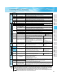
Parameter List
Parameter
Name
Number
Unit
Initial
Range
Value
Application
Set when you want to increase a
starting torque under V/F control,
or when the motor with a load will
0
Torque boost
0.1%
6%/4%/3%∗
0 to 30%
not rotate, resulting in an alarm
[OL] and a trip [OC1].
∗
Initial values differ according to the
inverter capacity. (0.75K or less/
1.5K to 3.7K/5.5K, 7.5K)
1
Maximum frequency
0.01Hz
120Hz
0 to 120Hz
2
Minimum frequency
0.01Hz
0Hz
0 to 120Hz
3
Base frequency
0.01Hz
60Hz
0 to 400Hz
Terminal Connection
Diagram
Terminal Specification
Explanation
classified as extended mode can be displayed.
Operation panel
Parameter unit
Both the parameters classified as simple mode and the parameters
Parameter
List
0
Parameters classified as simple mode can be displayed.
Set when the maximum output
frequency need to be limited.
Set when the minimum output
frequency need to be limited.
Set when the rated motor
Protective
Functions
(initial value)
frequency is 50Hz.
Options
9999
Outline
Dimension
Drawings
Description
Pr. 160
Standard
Specifications
POINT
Only simple mode parameters are displayed by the initial setting of Pr. 160 Extended function display selection. Set Pr.
160 Extended function display selection as required.
Features
For simple variable-speed operation of the inverter, the initial setting of the parameters may be used as they are. Set the
necessary parameters to meet the load and operational specifications. Parameter setting, change and check can be made
from the operation panel. For details of parameters, refer to the instruction manual.
This catalog explains based on the Japanese specifications.
Check the motor rating plate.
7
speed)
Acceleration time
60Hz
0 to 400Hz
0.01Hz
30Hz
0 to 400Hz
0.01Hz
10Hz
0 to 400Hz
0.1s
5s/10s∗
0 to 3600s
Set when changing the preset
speed in the parameter with a
terminal.
Acceleration/deceleration time can
be set.
∗
8
Deceleration time
0.1s
5s/10s∗
0 to 3600s
Initial values differ according to the
inverter capacity. (3.7K or less/
5.5K, 7.5K)
9
79
125
126
160
Electronic thermal O/L
relay
Operation mode
selection
Terminal 2 frequency
setting gain frequency
Terminal 4 frequency
setting gain frequency
Extended function
display selection
Instructions
6
(middle speed)
Multi-speed setting (low
0.01Hz
Rated
0.01A
inverter
The inverter protects the motor
0 to 500A
from overheat.
0, 1, 2, 3, 4, 6,
Set the rated motor current.
Select the start command location
current
1
0
0.01Hz
60Hz
7
and frequency setting location.
Frequency for the maximum value
0 to 400Hz
of the potentiometer (5V initial
FR-D700 Series
Specification
Difference List
5
(high speed)
Multi-speed setting
Warranty
International
FA Center
4
Multi-speed setting
value) can be changed.
Frequency for the maximum
0.01Hz
60Hz
0 to 400Hz
current input (20mA initial value)
can be changed.
Parameter which can be read from
1
9999
0, 9999
the operation panel and parameter
unit can be restricted.
16
z Extended mode parameter
REMARKS
y indicates simple mode parameters.
y The shaded parameters in the table allow its setting to be changed during operation even if "0" (initial value) is set in Pr. 77
Parameter write selection.
brake
DC injection
Basic functions
Function
JOG
operation
—
—
Acceleration/
deceleration time
Stall
setting
Multi-speed
prevention
—
—
—
0.1%
0.01Hz
0.01Hz
0.01Hz
0.01Hz
0.01Hz
0.01Hz
0.1s
0.1s
9
Electronic thermal O/L relay
0 to 500A
0.01A
10
DC injection brake operation frequency
0 to 120Hz
11
DC injection brake operation time
12
Initial
Value
Customer
Setting
Paramete
6/4/3% ∗1
120Hz
0Hz
60Hz
60Hz
30Hz
10Hz
5/10s ∗2
5/10s ∗2
Rated
inverter
current
0
1
2
3
4
5
6
7
8
0.01Hz
3Hz
10
0 to 10s
0.1s
0.5s
11
DC injection brake operation voltage
0 to 30%
0.1%
6/4% ∗3
12
13
14
Starting frequency
Load pattern selection
0 to 60Hz
0 to 3
0.01Hz
1
0.5Hz
0
13
14
15
Jog frequency
0 to 400Hz
0.01Hz
5Hz
15
16
Jog acceleration/deceleration time
0 to 3600s
0.1s
0.5s
16
17
18
19
MRS input selection
High speed maximum frequency
Base frequency voltage
0, 2, 4
120 to 400Hz
0 to 1000V, 8888, 9999
1
0.01Hz
0.1V
0
120Hz
9999
17
18
19
20
Acceleration/deceleration reference
frequency
1 to 400Hz
0.01Hz
60Hz
20
22
Stall prevention operation level
0 to 200%
0.1%
150%
22
23
Stall prevention operation level
compensation factor at double speed
0 to 200%, 9999
0.1%
9999
23
24
25
26
Multi-speed setting (speed 4)
Multi-speed setting (speed 5)
Multi-speed setting (speed 6)
0 to 400Hz, 9999
0 to 400Hz, 9999
0 to 400Hz, 9999
0.01Hz
0.01Hz
0.01Hz
9999
9999
9999
24
25
26
27
Multi-speed setting (speed 7)
0 to 400Hz, 9999
0.01Hz
9999
27
1
0
29
0, 1, 2
0 to 400Hz, 9999
0 to 400Hz, 9999
0 to 400Hz, 9999
0 to 400Hz, 9999
0 to 400Hz, 9999
0 to 400Hz, 9999
0, 0.01 to 9998
0, 1
0 to 100%
0 to 400Hz
1
0.01Hz
0.01Hz
0.01Hz
0.01Hz
0.01Hz
0.01Hz
0.001
1
0.1%
0.01Hz
0
9999
9999
9999
9999
9999
9999
0
0
10%
6Hz
30
31
32
33
34
35
36
37
40
41
42
0 to 400Hz, 9999
0.01Hz
9999
43
30
31
32
33
34
35
36
37
40
41
42
Frequency jump
Minimum
Setting
Increments
0 to 30%
0 to 120Hz
0 to 120Hz
0 to 400Hz
0 to 400Hz
0 to 400Hz
0 to 400Hz
0 to 3600s
0 to 3600s
—
detection
Setting Range
Torque boost
Maximum frequency
Minimum frequency
Base frequency
Multi-speed setting (high speed)
Multi-speed setting (middle speed)
Multi-speed setting (low speed)
Acceleration time
Deceleration time
29
Frequency
Name
0
1
2
3
4
5
6
7
8
—
—
—
17
Parameter
43
Acceleration/deceleration pattern
selection
Regenerative function selection
Frequency jump 1A
Frequency jump 1B
Frequency jump 2A
Frequency jump 2B
Frequency jump 3A
Frequency jump 3B
Speed display
RUN key rotation direction selection
Up-to-frequency sensitivity
Output frequency detection
Output frequency detection for reverse
rotation
0, 1, 2
9
Minimum
Setting
Increments
Initial
Value
0 to 3600s
0 to 3600s, 9999
0 to 30%, 9999
0 to 400Hz, 9999
0.1s
0.1s
0.1%
0.01Hz
5/10s ∗2
9999
9999
9999
0 to 200%, 9999
0.1%
9999
0.01A
9999
1
0
1
1
Frequency monitoring reference
0 to 500A, 9999
0, 5, 8 to 12, 14, 20,
23 to 25, 52 to 55, 61,
62, 64, 100
1 to 3, 5, 8 to 12, 14, 21,
24, 52, 53, 61, 62
0 to 400Hz
0.01Hz
56
Current monitoring reference
0 to 500A
0.01A
60Hz
Rated
inverter
current
Automatic
restart
functions
57
Restart coasting time
0, 0.1 to 5s, 9999
0.1s
9999
58
Restart cushion time
0 to 60s
0.1s
1s
—
—
—
59
60
65
0, 1, 2, 3
0, 9
0 to 5
1
1
1
0
0
0
—
66
0.01Hz
60Hz
—
67
68
69
70
Remote function selection
Energy saving control selection
Retry selection
Stall prevention operation reduction
starting frequency
Number of retries at fault occurrence
Retry waiting time
Retry count display erase
Special regenerative brake duty
1
0.1s
1
0.1%
0
1s
0
0%
—
71
Applied motor
1
0
71
—
—
—
72
73
74
1
1
1
1
1
1
72
73
74
—
75
1
14
—
—
—
77
78
79
80
82
PWM frequency selection
Analog input selection
Input filter time constant
Reset selection/disconnected PU
detection/PU stop selection
Parameter write selection
Reverse rotation prevention selection
Operation mode selection
Motor capacity
Motor excitation current
0, 1, 2
0, 1, 2
0, 1, 2, 3, 4, 6, 7
0.1 to 7.5kW, 9999
0 to 500A, 9999
1
1
1
0.01kW
0.01A
83
Rated motor voltage
0 to 1000V
0.1V
0
0
0
9999
9999
200V/400V
84
90
96
117
118
119
120
121
122
123
Rated motor frequency
Motor constant (R1)
Auto tuning setting/status
PU communication station number
PU communication speed
PU communication stop bit length
PU communication parity check
Number of PU communication retries
PU communication check time interval
PU communication waiting time setting
10 to 120Hz
0 to 50Ω , 9999
0, 11, 21
0 to 31 (0 to 247)
48, 96, 192, 384
0, 1, 10, 11
0, 1, 2
0 to 10, 9999
0, 0.1 to 999.8s, 9999
0 to 150ms, 9999
0.01Hz
0.001Ω
1
1
1
1
1
1
0.1s
1
60Hz
9999
0
0
192
1
2
1
0
9999
124
PU communication CR/LF selection
0, 1, 2
1
1
124
0 to 400Hz
0.01Hz
60Hz
125
0 to 400Hz
0.01Hz
60Hz
126
—
125
—
126
Terminal 2 frequency setting gain
frequency
Terminal 4 frequency setting gain
frequency
0 to 400Hz
0 to 10, 101 to 110
0.1 to 600s
0
0 to 30%
0, 1, 3, 13, 23, 40, 43,
50, 53
0 to 15
0, 1, 10, 11
0 to 8
0 to 3, 14 to 17
∗4
Features
Standard
Specifications
55
Outline
Dimension
Drawings
FM terminal function selection
Terminal Connection
Diagram
Terminal Specification
Explanation
54
Operation panel
Parameter unit
DU/PU main display data selection
Parameter
List
52
48
Paramete
Protective
Functions
51
Second acceleration/deceleration time
Second deceleration time
Second torque boost
Second V/F (base frequency)
Second stall prevention operation
current
Second electronic thermal O/L relay
Customer
Setting
Options
44
45
46
47
Setting Range
44
45
46
47
48
51
52
54
55
56
57
58
59
60
65
66
67
68
69
70
75
Instructions
Name
FR-D700 Series
Specification
Difference List
Parameter
Warranty
International
FA Center
PU connector communication
Motor constants
Retry
Monitor functions
Second functions
Function
18
77
78
79
80
82
83
84
90
96
117
118
119
120
121
122
123
Parameter
Setting Range
Minimum
Setting
Increments
Initial
Value
Customer
Setting
Paramete
0 to 400Hz, 9999
0.01Hz
9999
127
128
129
130
131
132
133
134
PID control automatic switchover
frequency
PID action selection
PID proportional band
PID integral time
PID upper limit
PID lower limit
PID action set point
PID differential time
0, 20, 21, 40 to 43
0.1 to 1000%, 9999
0.1 to 3600s, 9999
0 to 100%, 9999
0 to 100%, 9999
0 to 100%, 9999
0.01 to 10s, 9999
1
0.1%
0.1s
0.1%
0.1%
0.01%
0.01s
0
100%
1s
9999
9999
9999
9999
128
129
130
131
132
133
134
145
PU display language selection
0 to 7
1
0
145
—
146 ∗5
150
Built-in potentiometer switching
Output current detection level
Output current detection signal delay
time
Zero current detection level
Zero current detection time
Stall prevention operation selection
OL signal output timer
Extended function display selection
Frequency setting/key lock operation
selection
0, 1
0 to 200%
1
0.1%
1
150%
146
150
0 to 10s
0.1s
0s
151
0 to 200%
0 to 1s
0 to 31, 100, 101
0 to 25s, 9999
0, 9999
0.1%
0.01s
1
0.1s
1
5%
0.5s
0
0s
9999
152
153
156
157
160
0, 1, 10, 11
1
0
161
Current
detection
PID operation
127
151
161
Current detection
functions
—
Automatic restart
—
—
—
152
153
156
157
160
assignment
Cumulative
Input terminal function
monitor clear
—
—
19
Name
PU
Function
162
Automatic restart after instantaneous
power failure selection
0, 1, 10, 11
1
1
162
165
Stall prevention operation level for
restart
0 to 200%
0.1%
150%
165
166
Output current detection signal
retention time
0 to 10s, 9999
0.1s
0.1s
166
167
Output current detection operation
selection
0, 1
1
0
167
168
169
Parameter for manufacturer setting. Do not set.
170
Watt-hour meter clear
0, 10, 9999
1
9999
170
171
Operation hour meter clear
0, 9999
1
9999
171
178
STF terminal function selection
1
60
178
179
STR terminal function selection
1
61
179
180
181
RL terminal function selection
RM terminal function selection
1
1
0
1
180
181
182
RH terminal function selection
1
2
182
0 to 5, 7, 8, 10, 12,
14, 16, 18, 24, 25,
60, 62, 65 to 67, 9999
0 to 5, 7, 8, 10, 12,
14, 16, 18, 24, 25,
61, 62, 65 to 67, 9999
0 to 5, 7, 8, 10, 12,
14, 16, 18, 24, 25,
62, 65 to 67, 9999
168
169
Setting Range
A,B,C terminal function selection
232
233
234
235
236
237
238
239
240
241
244
Multi-speed setting (speed 8)
Multi-speed setting (speed 9)
Multi-speed setting (speed 10)
Multi-speed setting (speed 11)
Multi-speed setting (speed 12)
Multi-speed setting (speed 13)
Multi-speed setting (speed 14)
Multi-speed setting (speed 15)
Soft-PWM operation selection
Analog input display unit switchover
Cooling fan operation selection
245
Rated slip
0 to 50%, 9999
0.01%
9999
Slip compensation time constant
0.01 to 10s
0.01s
0.5s
246
0, 9999
1
9999
247
1
0
0.1s
9999
1
1
1%
1%
1%
1
1
1
0
100%
100%
100%
0
0
1
0
1
1
0
9999
267
268
269
0.01
0
295
Stop selection
—
251
255
256
257
258
259
260
Output phase loss protection selection
Life alarm status display
Inrush current limit circuit life display
Control circuit capacitor life display
Main circuit capacitor life display
Main circuit capacitor life measuring
PWM frequency automatic switchover
261
Power failure stop selection
0, 1, 2
—
—
—
267
268
269
—
295
Terminal 4 input selection
0, 1, 2
Monitor decimal digits selection
0, 1, 9999
Parameter for manufacturer setting. Do not set.
0, 0.01, 0.10, 1.00,
Magnitude of frequency change setting
10.00
Outline
Dimension
Drawings
190
Terminal Connection
Diagram
Terminal Specification
Explanation
Operation panel
Parameter unit
9999
9999
9999
9999
9999
9999
9999
9999
1
0
1
Parameter
List
0.01Hz
0.01Hz
0.01Hz
0.01Hz
0.01Hz
0.01Hz
0.01Hz
0.01Hz
1
1
1
192
Protective
Functions
99
Options
250
Life diagnosis
—
247
1
232
233
234
235
236
237
238
239
240
241
244
245
249
250
Instructions
246
Standard
Specifications
192
0, 1
0 to 100s,
1000 to 1100s,
8888, 9999
0, 1
(0 to 15)
(0 to 100%)
(0 to 100%)
(0 to 100%)
0, 1 (2, 3, 8, 9)
0, 1
stop
0
Paramete
RUN terminal function selection
249
Power failure
1
Customer
Setting
190
—
Password
Initial
Value
0, 1, 3, 4, 7, 8, 11 to 16,
25, 26, 46, 47, 64, 70,
80, 90, 91, 93, 95, 96,
98, 99, 100, 101, 103,
104, 107, 108,
111 to 116, 125, 126,
146, 147, 164, 170, 180,
190, 191, 193, 195,
196, 198, 199, 9999
0, 1, 3, 4, 7, 8, 11 to 16,
25, 26, 46, 47, 64, 70,
80, 90, 91, 95, 96, 98,
99, 100, 101, 103, 104,
107, 108, 111 to 116,
125, 126, 146, 147, 164,
170, 180, 190, 191, 195,
196, 198, 199, 9999
0 to 400Hz, 9999
0 to 400Hz, 9999
0 to 400Hz, 9999
0 to 400Hz, 9999
0 to 400Hz, 9999
0 to 400Hz, 9999
0 to 400Hz, 9999
0 to 400Hz, 9999
0, 1
0, 1
0, 1
Constant-power range slip
compensation selection
Earth (ground) fault detection at start
—
Minimum
Setting
Increments
Features
Name
FR-D700 Series
Specification
Difference List
Slip
compensation
—
—
—
Parameter
Warranty
International
FA Center
Multi-speed setting
Output terminal function assignment
Function
251
255
256
257
258
259
260
261
Password lock level
1 to 6, 101 to 106, 9999
1
9999
296
297
Password lock/unlock
1000 to 9999 (0 to 5,
9999)
1
9999
297
—
298
0 to 32767, 9999
1
9999
298
—
299
Frequency search gain
Rotation direction detection selection
at restarting
0, 1, 9999
1
0
299
function
296
20
constant
Output
Remote
Second motor
RS-485 communication
Function
time monitor
Current average
Communication
Maintenance
—
PID
338
339
340
342
Minimum
Setting
Increments
Initial
Value
0, 1
1
0
338
0, 1, 2
1
0
339
0, 1, 10
1
0
340
0, 1
1
0
342
Name
Communication operation command
source
Communication speed command
source
Communication startup mode selection
Communication EEPROM write
selection
Setting Range
Customer
Setting
Paramete
343
Communication error count
—
1
0
343
450
Second applied motor
0, 1, 9999
1
9999
450
495
Remote output selection
0, 1, 10, 11
1
0
495
496
Remote output data 1
0 to 4095
1
0
496
502
Stop mode selection at communication
error
0, 1, 2
1
0
502
503
Maintenance timer
0 (1 to 9998)
1
0
503
504
Maintenance timer alarm output set
time
0 to 9998, 9999
1
9999
504
549
Protocol selection
0, 1
1
0
549
551
PU mode operation command source
selection
2, 4, 9999
1
9999
551
555
Current average time
0.1 to 1s
0.1s
1s
555
556
Data output mask time
0 to 20s
0.1s
0s
556
557
Current average value monitor signal
output reference current
0 to 500A
0.01A
561
563
564
571
PTC thermistor protection level
Energization time carrying-over times
Operating time carrying-over times
Holding time at a start
0.5 to 30kΩ , 9999
(0 to 65535)
(0 to 65535)
0 to 10s, 9999
575
Output interruption detection time
0 to 3600s, 9999
576
Output interruption detection level
0 to 400Hz
0.01Ω
1
1
0.1s
Rated
inverter
current
9999
0
0
9999
561
563
564
571
0.1s
1s
575
0.01Hz
0Hz
576
557
900 to 1100%
0.1%
1000%
577
0 to 3600s, 9999
0 to 200%
0.1s
0.1%
9999
0
611
653
—
665
Acceleration time at a restart
Speed smoothing control
Regeneration avoidance frequency
gain
0 to 200%
0.1%
100
665
Input phase loss protection selection
0, 1
1
0
872
0, 1, 2
1
0
882
0.1V
400VDC/
780VDC ∗4
883
0.01Hz
6Hz
885
0.1%
100%
886
functions
Output interruption cancel level
611
653
872 ∗7
882
function
Protective
577
—
—
Regeneration avoidance
21
operation
—
—
—
—
Parameter
883
885
886
Regeneration avoidance operation
selection
Regeneration avoidance operation
level
Regeneration avoidance compensation
frequency limit value
Regeneration avoidance voltage gain
300 to 800V
0 to 10Hz, 9999
0 to 200%
0 to 4, 9999
1
9999
FM terminal calibration
—
—
—
Terminal 2 frequency setting bias
frequency
0 to 400Hz
0.01Hz
0Hz
Terminal 2 frequency setting bias
0 to 300%
0.1%
0%
Terminal 2 frequency setting gain
frequency
0 to 400Hz
0.01Hz
60Hz
Terminal 2 frequency setting gain
0 to 300%
0.1%
100%
Terminal 4 frequency setting bias
frequency
0 to 400Hz
0.01Hz
0Hz
Terminal 4 frequency setting bias
0 to 300%
0.1%
20%
Terminal 4 frequency setting gain
frequency
0 to 400Hz
0.01Hz
60Hz
Terminal 4 frequency setting gain
0 to 300%
0.1%
100%
Frequency setting voltage bias
frequency (built-in potentiometer)
0 to 400Hz
0.01Hz
0
Frequency setting voltage bias (built-in
potentiometer)
0 to 300%
0.1%
0
Frequency setting voltage gain
frequency (built-in potentiometer)
0 to 400Hz
0.01Hz
60Hz
Frequency setting voltage gain (built-in
potentiometer)
0 to 300%
0.1%
100%
PU buzzer control
PU contrast adjustment
0, 1
0 to 63
1
1
1
58
Pr.CL
Parameter clear
0, 1
1
0
ALLC
All parameter clear
0, 1
1
0
Er.CL
Faults history clear
0, 1
1
0
Pr.CH
Initial value change list
—
—
—
(903) ∗6
C4
Calibration parameters
(903) ∗6
C5
(904) ∗6
C6
(904) ∗6
126
(905) ∗6
C7
(905) ∗6
C22
(922) ∗5∗6
C23
(922) ∗5∗6
C24
(923) ∗5∗6
C25
Clear parameters
PU
(923) ∗5∗6
990
991
Differ according to capacities.
6%: 0.75K or less
4%: 1.5K to 3.7K
3%: 5.5K, 7.5K
Differ according to capacities.
5s: 3.7K or less
10s: 5.5K, 7.5K
Differ according to capacities.
6%: 0.1K, 0.2K
4%: 0.4K to 7.5K
∗4
The initial value differs according to the voltage class. (100Vclass, 200V class / 400V class)
∗5
Set this parameter when calibrating the operation panel built-in potentiometer for the FR-E500 series operation panel (PA02) connected with
cable.
The parameter number in parentheses is the one for use with the operation panel (PA02) for the FR-E500 series or parameter unit (FR-PU04/
FR-PU07).
∗6
∗7
Features
Cumulative power monitor digit shifted
times
Standard
Specifications
891
Outline
Dimension
Drawings
9999
Terminal Connection
Diagram
Terminal Specification
Explanation
1
Operation panel
Parameter unit
0 to 9999
Parameter
List
Free parameter 2
Protective
Functions
889
Paramete
888
889
891
C0
(900)
C2
(902)
C3
(902)
125
(903)
C4
(903)
C5
(904)
C6
(904)
126
(905)
C7
(905)
C22
(922)
C23
(922)
C24
Options
9999
Customer
Setting
Instructions
1
(902) ∗6
125
Initial value change list
Initial
Value
0 to 9999
(902) ∗6
C3
∗3
Minimum
Setting
Increments
Free parameter 1
C0
∗2
Setting Range
888
(900) ∗6
C2
∗1
Name
(923)
C25
(923)
990
991
Pr.CL
ALLC
FR-D700 Series
Specification
Difference List
—
Parameter
Warranty
International
FA Center
Free
parameter
Function
Available only for the three-phase power input specification model.
22
Er.CL
Pr.CH
Protective Functions
When a fault occurs, the inverter trips and the PU display automatically changes to any of the following fault or alarm indications.
Alarms
∗4
Warnings
∗3
Error message
∗2
Function Name
Description
Operation panel lock
Appears when operation was tried during operation panel lock.
Password locked
Appears when a password restricted parameter is read/written.
Parameter write error
Appears when an error occurred during parameter writing.
Inverter reset
Appears when the RES signal is on.
Stall prevention (overcurrent)
Appears during overcurrent stall prevention.
Stall prevention (overvoltage)
Appears during overvoltage stall prevention. Appears while the regeneration avoidance function is activated.
Regenerative brake prealarm ∗7
Appears if the regenerative brake duty reaches or exceeds 85% of the Pr. 70 Special regenerative brake duty
value. If the regenerative brake duty reaches 100%, a regenerative overvoltage (E. OV_) occurs.
Electronic thermal relay function prealarm
Appears when the electronic thermal O/L relay has reached 85% of the specified value.
PU stop
Appears when
Display
to
on the operation panel was pressed during external operation.
Maintenance signal output ∗7
Appears when the cumulative energization time has exceeded the maintenance output timer set value.
Undervoltage
Appears when the main circuit power became low voltage.
Fan alarm
Appears when the cooling fan remains stopped when operation is required or when the speed has
decreased.
Overcurrent trip during acceleration
Appears when an overcurrent occurred during acceleration.
Overcurrent trip during constant speed
Appears when an overcurrent occurred during constant speed operation.
Overcurrent trip during deceleration
or stop
Appears when an overcurrent occurred during deceleration and at a stop.
Regenerative overvoltage trip during
Appears when an overvoltage occurred during acceleration.
acceleration
Regenerative overvoltage trip during
Appears when an overvoltage occurred during constant speed operation.
constant speed
Fault
∗5
Regenerative overvoltage trip during
Appears when an overvoltage occurred during deceleration and at a stop.
deceleration or stop
Inverter overload trip
(electronic thermal relay function)
Appears when the electronic thermal relay function for inverter element protection was activated.
Motor overload trip
(electronic thermal relay function) ∗1
Appears when the electronic thermal relay function for motor protection was activated.
Fin overheat
Appears when the heatsink overheated.
Input phase loss ∗7 ∗8∗9
Appears if one of the three phases on the inverter input side opened. It may function if phase-tophase voltage of the three-phase power input becomes largely unbalanced.
Stall prevention
Appears when the output frequency drops to 1Hz as a result of deceleration due to the excess motor load.
Brake transistor alarm detection
This function stops the inverter output if an alarm occurs in the brake circuit, e.g. damaged brake
transistors. In this case, the inverter must be powered off immediately.
Output side earth (ground) fault
overcurrent at start ∗7
Appears when an earth (ground) fault occurred on the inverter's output side. (detects only at a start)
Output phase loss
If one of the three phases (U, V, W) on the inverter's output side (load side) is lost during inverter
operation (except during DC injection brake operation and when output frequency is under 1Hz),
inverter stops the output.
External thermal relay operation∗6 ∗7 Appears when the external thermal relay connected to the OH signal was activated.
∗1
∗2
∗3
∗4
∗5
∗6
∗7
∗8
∗9
23
PTC thermistor operation ∗7
Appears when resistance of PTC thermistor connected between terminal 2 and terminal 10 is more
than the value set in Pr. 561 PTC thermistor protection level.
Parameter storage device fault
Appears when operation of the element where parameters stored became abnormal. (control board)
PU disconnection
Appears when a communication error between the PU and inverter occurred, the communication
interval exceeded the permissible time during the RS-485 communication with the PU connector, or
communication errors exceeded the number of retries during the RS-485 communication.
Retry count excess ∗7
Appears when the operation was not restarted within the set number of retries.
CPU fault
Appears during the CPU and peripheral circuit errors occurred.
Output current detection value
exceeded ∗7
Appears when output current exceeded the output current detection level set by the parameter.
Inrush current limit circuit fault
Appears when the resistor of the inrush current limit circuit overheated.
Analog input fault
Appears if voltage(current) is input to terminal 4 when the setting in Pr.267 Terminal 4 input selection and
the setting of voltage/current input switch are different.
Safety circuit fault
Appears when safety circuit is malfunctioning.
Resetting the inverter initializes the internal thermal integrated data of the electronic thermal relay function.
The error message shows an operational error. The inverter output is not shut off.
Warnings are messages given before fault occur. The inverter output is not shut off.
Alarms warn the operator of failures with output signals. The inverter output is not shut off.
When faults occur, the protective functions are activated to inverter trip and output the fault signals.
The external thermal operates only when the OH signal is set in Pr. 178 to Pr. 182 (input terminal function selection).
This protective function does not function in the initial status.
Protective function activates when Pr.872 Input phase loss protection selection = "1".
This protective function is available with the three-phase power input specification model only.
/
Option and Peripheral Devices
Option list
FR-PA07
Parameter unit connection cable
FR-CB20
DIN rail attachment
FR-UDA01 to 03
AC reactor
FR-HAL
DC reactor
FR-HEL
This operation panel enables inverter operation and monitoring of frequency,
etc. from the enclosure surface
Cable for connection of operation panel or parameter unit
indicates a cable length. (1m, 3m, 5m)
Shared among
all models
Attachment for installation on DIN rail
Compatible with
the 3.7K or less
For harmonic current reduction and inverter input power factor improvement
(total power factor approx. 88%)
For harmonic current reduction and inverter input power factor improvement
(total power factor approx. 93%)
According to
capacities
EMC Directive compliant noise filter FR-E5NF
EMC Directive (EN61800-3 C3) compliant noise filter
400V: According
to capacities
Radio noise filter
For radio noise reduction (connect to the input side)
Line noise filter
FR-BIF(H)
FR- BSF01
FR- BLF
For line noise reduction
Filter pack
FR-BFP2
Combination of power factor improving DC reactor, zero phase reactor, and
capacitative filter
Brake resistor
MRS type,
MYS type
For increasing the regenerative braking capability (permissible duty 3%/6%ED)
High-duty brake resistor
Brake unit
Resistor unit
Discharging resistor
Power regeneration common
converter
Stand-alone reactor dedicated for
the FR-CV
High power factor converter
For increasing the regenerative braking capability (permissible duty 10%/
6%ED)
For increasing the braking capability of the inverter (for high-inertia load or
FR-BU2
negative load)
FR-BR
Brake unit, electrical-discharge resistor and resistor unit are used in
GZG, GRZG type
combination
FR-CV
FR-CVL
Unit which can return motor-generated braking energy back to the power
supply in common converter system
FR-HC
The high power factor converter switches the converter section on/off to
reshape an input current waveform into a sine wave, greatly suppressing
harmonics. (Used in combination with the standard accessory.)
Surge voltage suppression filter
Filter for suppressing surge voltage on motor
FR-BMF
FR series manual controller/
speed controller
DC tach. follower
Three speed selector
Motorized speed setter
Ratio setter
Speed detector
Master controller
Soft starter
Deviation detector
Preamplifier
Pilot generator
Others
Deviation sensor
Frequency setting potentiometer
Analog frequency meter
(64mm × 60mm)
Calibration resistor
FR Configurator SW3(VFD setup
software)
Three-phase
power input
model:
compatible with
0.4K or bigger
capacity
200V: For the
0.4K or more
FR-ABR
FR-ASF
Manual controller
Shared among
all models
For the 0.4K or
more
Standard
Specifications
Enclosure surface operation panel
Outline
Dimension
Drawings
This parameter unit enables parameter setting without connecting the inverter
to power supply.
Terminal Connection
Diagram
Terminal Specification
Explanation
FR-PU07BB(-L)
Operation panel
Parameter unit
Parameter unit with battery pack
Shared among
all models
Shared among
all models
(Available soon)
Parameter
List
Interactive parameter unit with LCD display
Protective
Functions
FR-PU07
FR-PU04
Options
Parameter unit (8 languages)
Applicable
Inverter
According to
capacities
400V: According
to capacities
400V: For the
5.5K or more
For independent operation. With frequency meter, frequency potentiometer and
start switch.
FR-AL
For synchronous operation (1.5VA) by external signal (0 to 5V, 0 to 10V DC)∗
For three speed switching, among high, middle and low speed operation
FR-AT
(1.5VA)∗
For remote operation. Allows operation to be controlled from several places
FR-FK
(5VA)∗
FR-FH
For ratio operation. The ratios of five inverters can be set (3VA)∗
FR-FP
For tracking operation by a pilot generator (PG) signal (3VA)∗
Master controller (5VA) for parallel operation of multiple (maximum 35)
FR-FG
inverters.∗
Shared among
For soft start and stop. Enables acceleration/deceleration in parallel operation
all models
FR-FC
(3VA)∗
For continuous speed control operation. Used in combination with a deviation
FR-FD
sensor or synchro (5VA)∗
FR-FA
Used as an A/V converter or arithmetic amplifier (3VA)∗
QVAH-10
For tracking operation. 70V/35VAC 500Hz (at 2500r/min)
For continuous speed control operation (mechanical deviation detection)
YVGC-500W-NS
Output 90VAC/90ºC
WA2W 1kΩ
For frequency setting. Wire-wound 2W 1kΩ type B characteristic
Dedicated frequency meter (graduated to 120Hz). Moving-coil type DC
YM206NRI 1mA
ammeter
RV24YN 10kΩ
For frequency meter calibration. Carbon film type B characteristic
Shared among
FR-SW3-SETUPSupports an inverter startup to maintenance.
all models
WE
FR-AX
Instructions
Applications, Specifications, etc.
FR-D700 Series
Specification
Difference List
Type
Warranty
International
FA Center
Stand-alone shared
Name
Features
By fitting the following options to the inverter, the inverter is provided with more functions.
∗ Rated power consumption. The power supply specifications of the FR series manual controllers and speed controllers are 200VAC 50Hz, 220V/220VAC 60Hz,
and 115VAC 60Hz.
24
Peripheral devices/cable size list
Single-Phase 100V Single-phase 200V
Three-phase 400V
Three-Phase 200V
Inverter type
∗1
Motor
Output
(kW)
Moulded Case Circuit Breaker (MCCB)∗1
or Earth Leakage Current Breaker (ELB)∗2
Magnetic
Contactor (MC)∗3
Reactor connection
Reactor connection
Without
With
Without
With
HIV Cables,
etc. (mm2)∗5
Reactor
R/L1,
S/L2, U, V, W
T/L3∗4
FR-HAL
FR-HEL
FR-D720-0.1K
0.1
30AF 5A
30AF 5A
S-N10
S-N10
2
2
0.4K ∗7
0.4K ∗7
FR-D720-0.2K
0.2
30AF 5A
30AF 5A
S-N10
S-N10
2
2
0.4K ∗7
0.4K ∗7
FR-D720-0.4K
0.4
30AF 5A
30AF 5A
S-N10
S-N10
2
2
0.4K
0.4K
FR-D720-0.75K
0.75
30AF 10A
30AF 5A
S-N10
S-N10
2
2
0.75K
0.75K
FR-D720-1.5K
1.5
30AF 15A
30AF 10A
S-N10
S-N10
2
2
1.5K
1.5K
FR-D720-2.2K
2.2
30AF 20A
30AF 15A
S-N10
S-N10
2
2
2.2K
2.2K
FR-D720-3.7K
3.7
30AF 30A
30AF 30A
S-N20, S-N21
S-N10
3.5
3.5
3.7K
3.7K
S-N20, S-N21 S-N20, S-N21
FR-D720-5.5K
5.5
50AF 50A
50AF 40A
5.5
5.5
5.5K
5.5K
FR-D720-7.5K
7.5
100AF 60A
50AF 50A
S-N25
S-N20, S-N21
14
8
7.5K
7.5K
FR-D740-0.4K
0.4
30AF 5A
30AF 5A
S-N10
S-N10
2
2
H0.4K
H0.4K
FR-D740-0.75K
0.75
30AF 5A
30AF 5A
S-N10
S-N10
2
2
H0.75K
H0.75K
FR-D740-1.5K
1.5
30AF 10A
30AF 10A
S-N10
S-N10
2
2
H1.5K
H1.5K
FR-D740-2.2K
2.2
30AF 15A
30AF 10A
S-N10
S-N10
2
2
H2.2K
H2.2K
FR-D740-3.7K
3.7
30AF 20A
30AF 15A
S-N10
S-N10
2
2
H3.7K
H3.7K
FR-D740-5.5K
5.5
30AF 30A
30AF 20A
S-N20, S-N21
S-N11, S-N12
3.5
2
H5.5K
H5.5K
FR-D740-7.5K
7.5
30AF 30A
30AF 30A
S-N20, S-N21 S-N20, S-N21
3.5
3.5
H7.5K
H7.5K
FR-D720S-0.1K
0.1
30AF 5A
30AF 5A
2
2
0.4K ∗7
0.4K ∗7
FR-D720S-0.2K
0.2
30AF 5A
30AF 5A
S-N10
S-N10
2
2
0.4K ∗7
0.4K ∗7
FR-D720S-0.4K
0.4
30AF 10A
30AF 10A
S-N10
S-N10
2
2
0.75K ∗7
0.75K ∗7
FR-D720S-0.75K
0.75
30AF 15A
30AF 10A
S-N10
S-N10
2
2
1.5K ∗7
1.5K ∗7
FR-D720S-1.5K
1.5
30AF 20A
30AF 20A
S-N10
S-N10
2
2
2.2K ∗7
2.2K ∗7
FR-D720S-2.2K
2.2
30AF 40A
30AF 30A
S-N20, S-N21
S-N10
3.5
2
3.7K ∗7
3.7K ∗7
FR-D710W-0.1K
0.1
30AF 10A
30AF 5A
S-N10
S-N10
2
2
0.75K ∗6, ∗7
— ∗8
FR-D710W-0.2K
0.2
30AF 10A
30AF 10A
S-N10
S-N10
2
2
1.5K ∗6, ∗7
— ∗8
FR-D710W-0.4K
0.4
30AF 15A
30AF 15A
S-N10
S-N10
2
2
2.2K ∗6, ∗7
— ∗8
FR-D710W-0.75K
0.75
30AF 30A
30AF 20A
S-N10
S-N10
3.5
2
3.7K ∗6, ∗7
— ∗8
S-N10
S-N10
Select an MCCB according to the inverter power supply capacity.
Install one MCCB per inverter.
MCCB
INV
IM
MCCB
INV
IM
∗2
For installations in the United States or Canada, use the class T type fuse certified by the UL and cUL.
∗3
Magnetic contactor is selected based on the AC-1 class. The electrical durability of magnetic contactor is 500,000 times. When the magnetic contactor is
used for emergency stop during motor driving, the electrical durability is 25 times.
When using the MC for emergency stop during motor driving or using on the motor side during commercial-power supply operation, select the MC with
class AC-3 rated current for the motor rated current.
∗4
When using single-phase power input, terminals are R/L1 and S/L2.
∗5
The cable size is that of the cable (HIV cable (600V class 2 vinyl-insulated cable) etc.) with continuous maximum permissible temperature of 75°C.
Assumes that the surrounding air temperature is 50°C or less and the wiring distance is 20m or less.
∗6
When connecting a single-phase 100V power input model to a power transformer (50kVA or more), install an AC reactor (FR-HAL) so that the performance
is more reliable.
∗7
The power factor may be slightly lower.
∗8
Single-phase 100V power input model is not compatible with DC reactor.
Note
y When the inverter capacity is larger than the motor capacity, select an MCCB and a magnetic contactor according to
the inverter type and cable and reactor according to the motor output.
y When the breaker on the inverter primary side trips, check for the wiring fault (short circuit), damage to internal parts
of the inverter, etc. Identify the cause of the trip, then remove the cause and power on the breaker.
25
Selecting the rated sensitivity current for the earth leakage current breaker
100
80
60
40
20
0
60
40
20
0
2 3.5 8 142238 80150
5.5
30 60100
Features
Standard
Specifications
(Note) 1 Install the earth leakage breaker (ELB) on the input side of the inverter.
2 In the
connection earthed-neutral system, the sensitivity current is blunt
against an earth (ground) fault in the inverter output side. Earthing (Grounding)
must conform to the requirements of national and local safety regulations and
electrical codes. (NEC section 250, IEC 536 class 1 and other applicable
standards)
0.75 2.2 5.5 11 20
0.4
1.5 3.7 7.5 15
Motor capacity (kW)
Example of leakage current of threephase induction motor during the
commercial power supply operation
(Totally-enclosed fan-cooled
type motor 400V60Hz)
1. 0
0. 7
0. 5
0. 3
0. 2
1.5
2.2
1
3
Leakage current
Ig2 (mA)
Standard Breaker
5m
× 66 ×
Leakage current
Ign (mA)
Leakage current Igi
(mA)
Motor leakage
current Igm (mA)
Total leakage
current (mA)
Rated sensitivity
current (mA) (≥ Ig ×
10)
2. 0
0. 1
Leakage current
Ig1 (mA)
= 0.11
1000m
0 (without noise filter)
1
1
3
connection))
Outline
Dimension
Drawings
Igm
Breaker Designed for
Harmonic and Surge
Suppression
0.1 0.2
leakage currents (mA)
leakage currents (mA)
Example of leakage current per 1km during
the commercial power supply operation
when the CV cable is routed in metal conduit
(Three-phase three-wire delta
connection 400V60Hz)
80
Ig2
Igi
(in the case of the above figure (400V class
0.1
0.07
0.05
0.03
0.02
Cable size (mm2)
100
Ign
zSelection example
1.0
0.7
0.5
0.3
0.2
2 3.5 8 142238 80150
5.5
30 60 100
120
Ig1
Terminal Connection
Diagram
Terminal Specification
Explanation
120
3φ
IM 400V
2.2kW
Inverter
(200V 60Hz)
Leakage currents (mA)
Leakage currents (mA)
(200V 60Hz)
Noise
filter
Operation panel
Parameter unit
Example of leakage current
of three-phase induction motor
during the commercial
power supply operation
Example of leakage current of
cable path per 1km during the
commercial power supply operation
when the CV cable is routed in
metal conduit
ELB
5.5mm2 × 60m
Parameter
List
y
Breaker designed for harmonic and surge suppression
Rated sensitivity current IΔn≥10×(Ig1+Ign+Igi+Ig2+Igm)
Standard breaker
Rated sensitivity current IΔn≥10×{Ig1+Ign+Igi+3X(Ig2+Igm)}
Ig1, Ig2: Leakage currents in wire path during commercial power supply
operation
Ign
: Leakage current of inverter input side noise filter
Igm
: Leakage current of motor during commercial power supply operation
Igi
: Leakage current of inverter unit
5.5mm2 × 5m
60m
× 66 ×
= 1.32
1000m
0.36
2.79
6.15
30
100
Protective
Functions
y
Example
Options
When using the earth leakage current breaker with the
inverter circuit, select its rated sensitivity current as follows,
independently of the PWM carrier frequency.
3.7 7.5 15
5.5 11 20
Cable size (mm )
Motor capacity (kW)
For " " connection, the amount of leakage current is appox.1/3 of the above value.
Warranty
International
FA Center
FR-D700 Series
Specification
Difference List
Instructions
2
26
Precautions for Operation/Selection
Precautions for use of the inverter
Installation
z Avoid hostile environment where oil mist, fluff, dust particles,
Safety Precautions
z To operate the inverter correctly and safely, be sure to read the
"instruction manual" before starting operation.
z This product has not been designed or manufactured for use
with any equipment or system operated under life-threatening
conditions.
z Please contact our sales office when you are considering using
this product in special applications such as passenger mobile,
medical,
aerospace,
nuclear,
power
or
undersea
relay
equipment or system.
z Although this product is manufactured under strict quality
control, safety devices should be installed when a serious
accident or loss is expected by a failure of this product.
z The load used should be a three-phase induction motor only.
Operation
not be used to make frequent starts and stops. It could cause
the inverter to fail.
z However, at this time, the motor cannot be brought to a sudden
stop. Hence, provide a mechanical stopping/holding mechanism
for the machine/equipment which requires an emergency stop.
z It will take time for the capacitor to discharge after shutoff of the
When accessing the inverter for
inspection, wait for at least 10 minutes after the power supply
has been switched off, and check to make sure that there are no
residual voltage using a tester or the like.
Wiring
z Application of power to the output terminals (U, V, W) of the
inverter will damage the inverter. Therefore, fully check the
wiring and sequence to ensure that wiring is correct, etc. before
powering on.
z The terminals P/+, PR, P1, N/- are provided for connection of a
dedicated option. Connect only a dedicated option. Do not short
the frequency setting power supply terminal 10 and common
terminal 5 or the terminal PC and terminal SD.
Power supply
z When the inverter is connected
under a large-capacity power
transformer (500kVA or more
transformer) or when a power
capacitor is to be switched over,
1500
Power
supply
system 1000
capacity
(kVA)
500
Range
requiring
installation
of the reactor
an excessive peak current may
flow in the power input circuit,
0
Wiring length (m)
10
damaging the inverter.
To prevent this, always install an optional AC reactor (FR-HAL).
When connecting a single-phase 100V power input model to a
power transformer (50kVA or more), install an AC reactor (FRHAL) so that the performance is more reliable.
z If a surge voltage occurs in the power supply system, this surge
energy may flow into the inverter, causing the inverter to display
overvoltage protection (E.OV
) and come to an inverter trip. To
prevent this, always install an optional AC reactor (FR-HAL).
27
place or put it in an ingress-protected "enclosed" enclosure.
When placing the inverter in an enclosure, determine the
cooling system and panel dimensions so that the surrounding
air temperature of the inverter is within the permissible value.
(refer to page 7 for the specified value)
z Do not install the inverter on wood or other combustible material
as it will be hot partly.
z Install the inverter in the vertical orientation.
Setting
z The inverter can be operated as fast as a maximum of 400Hz by
parameter setting. Therefore, incorrect setting can cause a
danger. Set the upper limit using the maximum frequency limit
setting function.
z A magnetic contactor (MC) provided on the input side should
inverter power supply.
etc. are suspended in the air, and install the inverter in a clean
z A setting higher than the initial value of DC injection brake
operation voltage or operation time can cause motor overheat
(electronic thermal relay error).
z Do not set Pr. 70 Special regenerative brake duty except for using
the optional brake resistor. This function is used to protect the
brake resistor from overheating. Do not set the value exceeding
permissible duty of the brake resistor.
Precautions for selection
Power transfer mechanism
Features
(reduction gear, belt, chain, etc.)
Inverter capacity selection
lubrication, causing seizure. When performing fast operation at
output current of the inverter.
higher than 60Hz, fully note that such operation will cause
strength shortage due to the noise, life or centrifugal force of the
Starting torque of the motor
power transfer mechanism.
z The start and acceleration characteristics of the motor driven by
the inverter are restricted by the overload current rating of that
Instructions for overload operation
inverter. Generally the torque characteristic is less than when
z When performing operation of frequent start/stop of the inverter,
the motor is started by a commercial power supply. If torque
rise/fall in the temperature of the transistor element of the
boost adjustment or general-purpose magnetic flux vector
inverter will repeat due to a repeated flow of large current,
control cannot provide enough torque when a large starting
shortening the life from thermal fatigue. Since thermal fatigue is
torque is necessary, select the inverter of one rank higher
related to the amount of current, the life can be increased by
capacity or increase the capacities of both the motor and
reducing current at locked condition, starting current, etc.
inverter.
Decreasing current may increase the life. However, decreasing
current will result in insufficient torque and the inverter may not
Acceleration/deceleration times
start. Therefore, choose the inverter which has enough
z The acceleration/deceleration time of the motor depends on the
allowance for current.
Outline
Dimension
Drawings
continuous operation at low speed only may deteriorate oil
1.1 times the total rated motor current is less than the rated
Terminal Connection
Diagram
Terminal Specification
Explanation
or similar device is used in the power transfer system, note that
parallel with a single inverter, select the inverter capacity so that
Operation panel
Parameter unit
z When operating a special motor or more than one motor in
Standard
Specifications
z When an oil-lubricated gear box, speed change/reduction gear
the load (J).
z When the stall prevention function is activated during
acceleration/deceleration,
increase
the
acceleration/
Parameter
List
motor-generated torque, load torque and moment of inertia of
z To decrease the acceleration/deceleration time, increase the
torque boost value (setting of a too large value may activate the
stall prevention function at a start, longer the acceleration time),
Protective
Functions
deceleration time as the actual time may become longer.
use the general-purpose magnetic flux vector control or
Options
increase the inverter and motor capacities. To decrease the
deceleration time, it is necessary to add optional brake resistor
MRS type, MYS type, FR-ABR (for the 0.4K or more), the brake
unit (FR-BU2), power regeneration common converter (FR-CV),
Warranty
International
FA Center
FR-D700 Series
Specification
Difference List
Instructions
or a similar device to absorb braking energy.
28
Precautions for Peripheral Device Selection
Installation and selection of moulded
case circuit breaker
Install a moulded case circuit breaker (MCCB) on the power
receiving side to protect the wiring of the inverter input side. For
MCCB selection, refer to page 25 since it depends on the inverter
power supply side power factor (which changes depending on the
power supply voltage, output frequency and load). Especially for a
completely electromagnetic MCCB, one of a slightly large capacity
must be selected since its operation characteristic varies with
harmonic currents. (Check it in the data of the corresponding
breaker.) As an earth leakage current breaker, use the Mitsubishi
earth leakage current breaker designed for harmonics and surge
suppression. (Refer to page 26)
When installing a moulded case circuit breaker on the output side
of the inverter, contact each manufacturer for selection of the
moulded case circuit breaker.
Handling of the inverter input side
magnetic contactor
z For operation via external terminal (terminal STF or STR used),
provide an input side MC to prevent an accident caused by a
natural restart at power recovery after a power failure, such as
an instantaneous power failure, and to ensure safety for
maintenance work. Do not use this magnetic contactor to make
frequent starts and stops. (The switching life of the inverter input
circuit is about 1,000,000 times.) For parameter unit operation,
an automatic restart after power failure is not made and the MC
cannot be used to make a start. Note that the primary side MC
may be used to make a stop but the regenerative brake specific
to the inverter does not operate and the motor is coasted to a
stop.
z Installation of a magnetic contactor on the primary side is
recommended. Since when cycle operation or heavy-duty
operation is performed with an optional brake resistor
connected, overheat and burnout of the electrical-discharge
resistor can be prevented if a regenerative brake transistor is
damaged due to insufficient heat capacity of the electricaldischarge resistor and excess regenerative brake duty. In this
case, shut-off the magnetic contactor when fault occurs and
inverter trips.
Handling of the inverter output side
magnetic contactor
Switch the magnetic contactor between the inverter and motor
only when both the inverter and motor are at a stop. When the
magnetic contactor is turned on while the inverter is operating,
overcurrent protection of the inverter and such will activate. When
an MC is provided for switching to the commercial power supply,
for example, switch it on/off after the inverter and motor have
stopped.
Thermal relay installation
The inverter has an electronic thermal relay function to protect the
motor from overheating. However, when running multiple motors
with one inverter or operating a multi-pole motor, provide a thermal
relay (OCR) between the inverter and motor. In this case, set the
electronic thermal relay function of the inverter to 0A. And for the
setting of the thermal relay, add the line-to line leakage current
(refer to page 30) to the current value on the motor rating plate.
For low-speed operation where the cooling capability of the motor
reduces, it is recommended to use a thermal relay protector
incorporated motor.
29
Measuring instrument on the output
side
When the inverter-to-motor wiring length is large, especially in the
400V class, small-capacity models, the meters and CTs may
generate heat due to line-to-line leakage current. Therefore,
choose the equipment which has enough allowance for the current
rating.
Disuse of power factor improving
capacitor (power capacitor)
The power factor improving capacitor and surge suppressor on the
inverter output side may be overheated or damaged by the
harmonic components of the inverter output. Also, since an
excessive current flows in the inverter to activate overcurrent
protection, do not install a capacitor or surge suppressor. For
power factor improvement, use a DC reactor.
Wire thickness and wiring distance
When the wiring length between the inverter and motor is long,
use thick wires so that the voltage drop of the main circuit cable is
2% or less especially at low frequency output. (A selection
example for the wiring distance of 20m is shown on page 25)
Especially at a long wiring distance, the maximum wiring length
should be within the length in the table below since the overcurrent
protection function may be misactivated by the influence of a
charging current due to the stray capacitances of the wiring.
(The overall wiring length for connection of multiple motors should
be within the value in the table below.)
Pr. 72 Setting
0.1K
(carrier frequency)
100V
200m
1 or less 200V
400V
—
100V
30m
2 to 15 200V
400V
—
0.2K
0.4K
0.75K
1.5K
2.2K
3.7K or
more
200m
300m
500m
500m
500m
500m
—
200m
200m
300m
500m
500m
100m
200m
300m
500m
500m
500m
—
30m
100m
200m
300m
500m
When using the automatic restart after instantaneous power failure
function with wiring length exceeding below, select "without
frequency search" (Pr.162 = "1, 11").
Motor Capacity
0.1K
0.2K
0.4K or more
Wiring Length
20m
50m
100m
Use the recommended connection cable when connecting the
parameter unit.
For remote operation via analog signal, wire the control cable
between the operation box or operation signal and inverter within
30m and away from the power circuits (main circuit and relay
sequence circuit) to prevent induction from other devices.
When using the external potentiometer instead of the parameter
unit to set the frequency, use a shielded or twisted cable, and do
not earth (ground) the shield, but connect it to terminal 5 as shown
below.
(3)
(2)
(1)
Frequency setting Twisted
potentiometer
cable
10
2
5
(3)
Shielded cable
(2)
(1)
Frequency setting
potentiometer
10
2
5
Earth (Ground)
carrier frequency of the inverter will increase the leakage current.
inverter. (Do not use the case and chassis)
Therefore, take the following measures. Select the earth leakage
current breaker according to its rated sensitivity current,
independently of the carrier frequency setting. (Refer to page 26)
following measure example and consider taking the measures.
Type
Influence and Measures
y Leakage currents may flow not only into the inverter's
Depending on the installation condition, the inverter may be
own line but also into the other line through the earth
affected by noise in a non-low noise (initial) status.
(ground) cable, etc. These leakage currents may
z The noise level can be reduced by decreasing the carrier
operate earth (ground) leakage circuit breakers and
earth leakage relays unnecessarily.
frequency (Pr. 72).
z As measures against AM radio broadcasting noise, radio noise
filter FR-BIF produces an effect.
z As measures against sensor malfunction, line noise filter FR-
z Countermeasures
Influence and
measures
y If the carrier frequency setting is high, decrease the Pr.
72 PWM frequency selection setting.
Note that motor noise increases. Select Pr. 240 Soft-
BSF01, FR-BLF produces an effect.
PWM operation selection to make the sound inoffensive.
z As measures against induction noise from the power cable of
y By using earth leakage circuit breakers designed for
the inverter, an effect is produced by putting a distance of 30cm
harmonic and surge suppression in the inverter's own
(at least 10cm) or more and using a twisted pair shielded cable
line and other line, operation can be performed with the
as a signal cable. Do not earth (ground) shield but connect it to
carrier frequency kept high (with low noise).
signal common cable.
Inverter
FR- BLF
FR- BSF01
on inverter input side.
Decrease
Enclosure carrier frequency
Inverter
power
supply
Install capacitor type FR-BIF filter
on inverter input side.
Separate inverter and power
line by more than 30cm (at
least 10cm) from sensor circuit.
Control
power
supply
Do not earth (ground)
enclosure directly.
FRBSF01
Inverter
FRBIF
Power
supply
for sensor
FRBSF01
Install common mode filter
on inverter output side.
FR- BLF
FR- BSF01
Undesirable
current path
Use a twisted pair shielded cable
Sensor
C
NV2
IM Motor
Use 4-core cable for motor
power cable and use one
cable as earth (ground) cable.
Motor
C
Leakage
breaker
Motor
C
Leakage
breaker
Line leakage current
Type
Options
Install common mode filter
NV1
Power
supply
Protective
Functions
Noise reduction examples
Influence and Measures
• This leakage current flows via a static capacitance
Do not earth (ground) shield but
connect it to signal common cable.
between the inverter output cables.
Do not earth (ground) control cable.
• The external thermal relay may be operated
Instructions
electromagnetic noise tends to increase. Therefore, refer to the
To-earth (ground) leakage currents
unnecessarily by the harmonics of the leakage current.
When the wiring length is long (50m or more) for the
400V class model, the external thermal relay is likely to
operate unnecessarily because the ratio of the leakage
current to the rated motor current increases.
Influence and
measures
z Countermeasures
• Use Pr.9 Electronic thermal O/L relay.
• If the carrier frequency setting is high, decrease the Pr.
72 PWM frequency selection setting.
Note that motor noise increases. Select Pr. 240 Soft-PWM
operation selection to make the sound inoffensive.
To ensure that the motor is protected against line-to-
FR-D700 Series
Specification
Difference List
When performing low-noise operation at higher carrier frequency,
Warranty
International
FA Center
Noise
Standard
Specifications
frequency, etc., low acoustic noise operation at the increased
earth (ground) terminal of the inverter to earth (ground) the
Outline
Dimension
Drawings
Since its value depends on the static capacitances, carrier
the inverter and motor before use. In addition, always use the
Terminal Connection
Diagram
Terminal Specification
Explanation
and earth and in the motor, through which a leakage current flows.
due to high-speed switching operation. Be sure to earth (ground)
Operation panel
Parameter unit
Capacitances exist between the inverter I/O cables, other cables
leakage currents occur than in the non-low acoustic noise mode
Parameter
List
When the inverter is run in the low acoustic noise mode, more
Features
Leakage currents
line leakage currents, it is recommended to use a
temperature sensor to directly detect motor
temperature.
MCCB
Undesirable
current path
Power
supply
MC
Thermal relay
Motor
IM
Inverter
Line-to-line static
capacitances
Line-to-line leakage currents path
30
zHarmonic suppression guideline
For compliance to "Harmonic suppression guideline of the
transistorized inverter (input current of 20A or less) for consumers
other than specific consumers" published by JEMA.
Harmonic currents flow from the inverter to a power receiving point
via a power transformer. The harmonic suppression guideline was
established to protect other consumers from these outgoing
Input
harmonic currents.
Power
The three-phase 200V input specifications 3.7kW or less, single-
Supply
phase 200V input specifications 2.2kW or less, single-phase 100V
Single-
Target
Connect the AC reactor or DC reactor
phase
input specifications 0.75kW or less are previously covered by
Countermeasures
Capacity
0.75kW or less
recommended in a catalog or an
100V
"Harmonic suppression guideline for household appliances and
instruction manual.
Reference materials
Single-
general-purpose products" and other models are covered by
phase
"Harmonic suppression guideline for consumers who receive high
2.2kW or less
y "Harmonic suppression guideline of the
general-purpose inverter (input current of
200V
voltage or special high voltage". However, the transistorized
20A or less)"
Three-
inverter has been excluded from the target products covered by
phase
"Harmonic suppression guideline for household appliances and
JEM-TR226 (revised in Dec. 2003): Japan
3.7kW or less
Electrical Manufacturer's Association
200V
general-purpose products" in January 2004 and "Harmonic
suppression guideline for household appliances and generalpurpose products" was repealed on September 6, 2004.
All capacity and all models of general-purpose inverter used by
specific consumers are covered by "Harmonic suppression
zCalculation of outgoing harmonic current
Outgoing harmonic current = fundamental wave current (value converted
from received power voltage) × operation ratio × harmonic content
yOperation ratio: Operation ratio = actual load factor operation
guideline for consumers who receive high voltage or special high
time ratio during 30 minutes
voltage".
yHarmonic content: Found in Table.
y "Harmonic suppression guideline for consumers who receive high
voltage or special high voltage"
This guideline sets forth the maximum values of harmonic currents
outgoing from a high-voltage or especially high-voltage consumer
who will install, add or renew harmonic generating equipment. If any
of the maximum values is exceeded, this guideline requires that
consumer to take certain suppression measures.
Users who use models other than the target models are not covered
by the guideline. However, we ask to connect an AC reactor or a DC
reactor as before to the users who are not covered by the guideline.
For compliance to the harmonic suppression guideline for
consumers who receive high voltage or special high voltage
Input
Power
Supply
Table 1: Harmonic Contents (Values at the fundamental current of 100%)
Three-phase
bridge
(Capacitor
smoothing)
Single-phase
bridge
(Capacitor
smoothing)
∗
Reactor
5th
Not used
Used
(AC side)
Used
(DC side)
Used
(AC, DC sides)
Not used
65
41
8.5
7.7
4.3
3.1
2.6
1.8
38
14.5
7.4
3.4
3.2
1.9
1.7
1.3
30
13
8.4
5.0
4.7
3.2
3.0
2.2
28
9.1
7.2
4.1
3.2
2.4
1.6
1.4
50
24
5.1
4.0
1.5
1.4
⎯
⎯
6.0
3.9
1.6
1.2
0.6
0.1
⎯
⎯
Used
(AC side)*
7th 11th 13th 17th 19th 23rd 25th
The harmonic contents for "single-phase bridge/with reactor" in the table
1 are values when the reactor value is 20%. Since a 20% reactor is large
Target
Countermeasures
Capacity
and considered to be not practical, harmonic contents when a 5% reactor
is used is written in the technical data JEM-TR201 of The Japan
Make a judgment based on "Harmonic
Electrical Manufacturers'
suppression guideline for consumers who
Association and this value is recommended for calculation for the actual
receive high voltage or special high voltage"
practice.
issued by the Japanese Ministry of Economy,
September 1994 and take measures if
100V
necessary. For calculation method of power
supply harmonics, refer to materials below.
Single-phase
200V
All
Reference materials
Three-phase
capacities
y "Harmonic suppression measures of the
200V
inverter"
Three-phase
Jan. 2004 Japan Electrical Manufacturer's
400V
Association
y "Calculation method of harmonic current of
the general-purpose inverter used by
specific consumers"
JEM-TR201 (revised in Dec. 2003): Japan
Electrical Manufacturer's Association
Japan Electrical Manufacturer's Association
31
Inverter Drive
Rated
Current [A]
0.4
0.75
1.5
2.2
3.7
5.5
7.5
200V 400V
Rated Capacity (kVA)
Single-phase
Table 2: Rated Capacities and Outgoing Harmonic Currents for Three-phase
Fundamental Wave Current
Converted from 6.6kV (mA)
International Trade and Industry) in
Applied
Motor kW
Trade and Industry (formerly Ministry of
Outgoing Harmonic Current Converted from
6.6kV (mA)
(No reactor, 100% operation ratio)
5th
7th
11th 13th 17th 19th 23rd 25th
1.61
0.81
49
0.57 31.85 20.09 4.165 3.773 2.107 1.519 1.274 0.882
2.74
1.37
83
0.97 53.95 34.03 7.055 6.391 3.569 2.573 2.158 1.494
5.50
2.75
167
1.95 108.6 68.47 14.20 12.86 7.181 5.177 4.342 3.006
7.93
3.96
240
2.81 156.0 98.40 20.40 18.48 10.32 7.440 6.240 4.320
13.0
6.50
394
4.61 257.1 161.5 33.49 30.34 16.94 12.21 10.24 7.092
19.1
9.55
579
6.77 376.1 237.4 49.22 44.58 24.90 17.95 15.05 10.42
25.6
12.8
776
9.07 504.4 318.2 65.96 59.75 33.37 24.06 20.18 13.97
FR-D700 Series Specification Difference List
Indicator Output
Terminal Function
Traverse Function
Pr.592 to Pr.597
CHT Specification
Sink logic
Sink logic
Source logic
Sink logic
SD
SD
PC
SD
FM (Digital output)
AM (Analog output)
AM (Analog output)
AM (Analog output)
60Hz
60Hz
50Hz
50Hz
9999
0
9999
0
Pr.54 FM terminal function
selection,
Pr.900 FM terminal
calibration
Without
9999
8888
9999
1
1
1
0
9999
9999
0
1
1
Pr.158 AM terminal function Pr.158 AM terminal function Pr.158 AM terminal function
selection,
selection,
selection,
Pr.901 AM terminal
Pr.901 AM terminal
Pr.901 AM terminal
calibration
calibration
calibration
Without
With
Features
Standard
Specifications
+, -
Outline
Dimension
Drawings
P, N
Terminal Connection
Diagram
Terminal Specification
Explanation
L1, N
Operation panel
Parameter unit
R, S
Parameter
List
L1, L2, L3
Protective
Functions
R, S, T
Options
Main Circuit Terminal
Name
AC Power Input
Three-phase Input
Single-phase Input
Brake Unit
Connection
Control Terminal Logic
Initial Setting
Control Terminal
Contact Input Common
Terminal
Initial Setting
Monitor Output
Terminal For Indicator
Parameter
Pr.3, Pr.4, Pr.20,
Pr.55, Pr.66, Pr.84,
Pr.125, Pr.126, Pr.903,
Pr.905, Pr.923
Initial Value
Pr.19 Initial Value
Pr.145 Initial Value
Pr.160 Initial Value
Pr.249 Initial Value
EC Specification
With
Instructions
Applicable Capacity
Type
NA Specification
FR-D720-008 to 318-NA
FR-D740-012 to 160-EC
FR-D740-012 to 160-NA
FR-D740-0.4K to 7.5K-CHT
FR-D720S-008 to 100-NA FR-D720S-008 to 100-EC FR-D720S-0.1K to 2.2K-CHT
FR-D710W-008 to 042-NA Type : Rated current value Type : Rated capacity (kW)
Type : Rated current value
FR-D700 Series
Specification
Difference List
Japanese Specification
FR-D720-0.1K to 7.5K
FR-D740-0.4K to 7.5K
FR-D720S-0.1K to 2.2K
FR-D710W-0.1K to 0.75K
Type : Rated capacity (kW)
Warranty
International
FA Center
Item
32
Warranty
1. Gratis warranty period and coverage
[Gratis warranty period]
Note that an installation period of less than one year after installation in your company or your customer's premises or a
period of less than18 months (counted from the date of production) after shipment from our company, whichever is shorter,
is selected.
[Coverage]
(1) Diagnosis of failure
As a general rule, diagnosis of failure is done on site by the customer.
However, Mitsubishi or Mitsubishi service network can perform this service for an agreed upon fee upon the customer's
request.
There will be no charges if the cause of the breakdown is found to be the fault of Mitsubishi.
(2) Breakdown repairs
There will be a charge for breakdown repairs, exchange replacements and on site visits for the following four conditions
even in gratis warranty period, otherwise there will be no charge.
1)Breakdowns due to improper storage, handling, careless accident, software or hardware design by the customer.
2)Breakdowns due to modifications of the product without the consent of the manufacturer.
3)Breakdowns resulting from using the product outside the specified specifications of the product.
4)Breakdowns that are outside the terms of warranty.
Since the above services are limited to Japan, diagnosis of failures, etc. are not performed abroad.
If you desire the after service abroad, please register with Mitsubishi. For details, consult us in advance.
2. Exclusion of opportunity loss from warranty liability
Regardless of the gratis warranty term, compensation to opportunity losses incurred to your company or your customers by
failures of Mitsubishi products and compensation for damages to products other than Mitsubishi products and other
services are not covered under warranty.
3. Repair period after production is discontinued
Mitsubishi shall accept product repairs for seven years after production of the product is discontinued.
4. Terms of delivery
In regard to the standard product, Mitsubishi shall deliver the standard product without application settings or adjustments
to the customer and Mitsubishi is not liable for on site adjustment or test run of the product.
33
Standard
Specifications
Features
International FA Center
UK FA Center
European FA Center
Korean
FA Center
Beijing FA Center
North American FA Center
Tianjin FA Center
Shanghai FA Center
Guangzhou FA Center
Taiwan FA Center
Outline
Dimension
Drawings
Central and Eastern Europe
FA Center
Thailand FA Center
MITSUBISHI ELECTRIC AUTOMATION, INC.
500 Corporate Woods Parkway, Vernon Hills, IL60061 U.S.A
TEL. +1-847-478-2100 FAX. +1-847-478-0327
zTaiwan FA Center
zASEAN FA Center
MITSUBISHI ELECTRIC ASIA PTE, LTD.
307 Alexandra Road #05-01/02, Mitsubishi Electric Building,
Singapore 159943
TEL. +65-6470-2480 FAX. +65-6476-7439
Options
zNorth American FA Center
Protective
Functions
Parameter
List
Operation panel
Parameter unit
ASEAN FA Center
Terminal Connection
Diagram
Terminal Specification
Explanation
Hong Kong FA Center
zBeijing FA Center
zEuropean FA Center
MITSUBISHI ELECTRIC EUROPE B. V. GERMAN BRANCH
Gothaer Strasse 8, D-40880 Ratingen, Germany
TEL. +49-2102-486-0 FAX. +49-2102-486-1120
zUK FA Center
MITSUBISHI ELECTRIC EUROPE B. V. UK BRANCH
MITSUBISHI ELECTRIC AUTOMATION (SHANGHAI) LTD. Travellers Lane, Hatfield, Hertfordshire, AL10 8XB, UK.
TEL. +44-1707-276100 FAX. +44-1707-278695
BEIJING OFFICE
9F Office Tower 1, Henderson Center, 18 Jianguomennei
zThailand FA Center
Avenue, Dongcheng District, Beijing, China 100005
MITSUBISHI ELECTRIC AUTOMATION (THAILAND) CO., LTD.
TEL. +86-10-6518-8830 FAX. +86-10-6518-8030
Bang-Chan Industrial Estate No.111, Soi Serithai 54,
zTianjin FA Center
T.Kannayao, A.Kannayao, Bangkok 10230
MITSUBISHI ELECTRIC AUTOMATION (SHANGHAI) LTD. TEL. +66-2-906-3238 FAX. +66-2-906-3239
TIANJIN OFFICE
B-2 801/802, Youyi Building, No.50 Youyi Road, Hexi District, zGuangzhou FA Center
MITSUBISHI ELECTRIC AUTOMATION (SHANGHAI) LTD.
Tianjin, China 300061
GUANGZHOU OFFICE
TEL +86-22-2813-1015 FAX. +86-22-2813-1017
Rm.1609, North Tower, The Hub Center, No.1068, Xing Gang
zShanghai FA Center
East Road, Haizhu District, Guangzhou, China 510335
TEL. +86-20-8923-6713 FAX. +86-20-8923-6715
MITSUBISHI ELECTRIC AUTOMATION (SHANGHAI) LTD.
4/F Zhi Fu Plazz, No.80 Xin Chang Road, Shanghai, China
zCentral and Eastern Europe FA Center
200003
MITSUBISHI ELECTRIC EUROPE B.V. CZECH BRANCH
TEL. +86-21-6121-2460 FAX. +86-21-6121-2424
Avenir Business Park, Radlicka 714/113a,158 00 Praha 5, Czech
Republic
TEL. +420-251-551-470 FAX. +420-251-551-471
FR-D700 Series
Specification
Difference List
MITSUBISHI ELECTRIC AUTOMATION KOREA CO., LTD.
B1F,2F, 1480-6, Gayang-Dong, Gangseo-Gu, Seoul, 157-200,
Korea
TEL. +82-2-3660-9607 FAX. +82-2-3664-0475
Warranty
International
FA Center
zKorean FA Center
Instructions
zHong Kong FA Center
SETSUYO ENTERPRISE CO., LTD.
6F No.105, Wu Kung 3rd RD, Wu-Ku Hsiang Taipei Hsien, MITSUBISHI ELECTRIC AUTOMATION (Hong Kong) LTD.
248, Taiwan
10th Floor, Manulife Tower, 169 Electric Road, North Point, Hong Kong
TEL. +886-2-2299-2499 FAX. +886-2-2299-2509
TEL.+852-2887-8870 FAX. +852-2887-7984
34