1
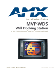
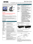
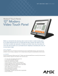
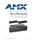
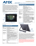
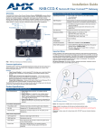
Quick Start Guide
MVP-7500 Modero Wireless Touch Panel (Firmware version G4)
For more detailed installation, configuration, programming, file transfer, and
operating instructions refer to the MVP-7500 and MVP-8400 Modero
ViewPoint Touch Panels Instruction Manual, available on-line at
www.amx.com.
MVP-7500 Panels Specifications (Cont.)
Panel LCD
Parameters:
•
•
•
•
•
•
•
•
External
Components:
• Docking Station Interface Connector: Metallic strip connector located
on the bottom of the MVP provides communication and power between
the MVP and the optional docking station.
• LEDs: Two sets of NetLinx programmable LEDs (support On, Off,
and Blink).
• Mini-USB Connector: 5-pin mini-USB connector used for programming
and touch panel file transfer to and from the PC.
• Stylus slot: Illuminated slot where the included stylus can be stored,
located on the left side of the MVP.
• Power Connector: 6mm barrel-style power jack - accepts the power
cord from the PS4.4 power supply (included).
Internal
Components:
• Wireless Interface card: Provides 802.11b (Type I) wireless connectivity
between the panel and a Wireless Access Point (WAP).
• IR Emitters: Transmit IR over 20 feet (6.10 m) from the panel.
• Internal Buzzer: Emits a Piezo electric tone.
• Battery Compartment: Houses up to two MVP-BP battery packs (one
MVP-BP is included with the panel).
External Buttons:
• Nine external programmable pushbuttons (four located on the left of the
LCD and five located on the right)
• All of these buttons are user-programmable to activate other
commands (context-sensitive for each page).
Power Modes:
• ON: Panel is fully functional.
• STANDBY: Panel uses low power, the LCD/backlight is shutdown,
LEDs still function. Panel resumes the ON mode in ~ 1 second.
• OFF: On-board programs not running, touch screen still powered, LED
not functional. Panel resumes the ON mode in ~ 30 seconds.
Operating/Storage
Environments:
•
•
•
•
Included
Accessories
• MVP-7500 Modero Wireless Touch Panel (Firmware version G4)
Quick Start Guide (93-5965-01)
• MVP-BP battery (FG5965-20)
• PS4.4 Power Supply (13.5 VDC) (FG423-44)
• Stylus
Optional
Accessories:
•
•
•
•
•
•
•
•
FIG. 1 MVP-7500 Wireless Touch Panel (FG5965-01)
ATTENTION!
Verify the NetLinx Master Firmware is build 117 or greater for the ME260 and
NI-Series Controllers. Verify the TPDesign4 program being used is Version 2.2
or higher. Earlier versions of the Master firmware and TPD4 software are
incompatible with these panels.
Overview
The AMX MVP-7500 panel (FG5965-01) uses an internal wireless compact flash
card to communicate with a NetLinx Master via an off-the-shelf 802.11b Wireless
Access Point. MVP units utilize a 7.5" Color Passive LCD to display a 640 x 480
pixel image using over 4000 colors and features programmable firmware that
can be upgraded via either the wireless card or the mini-USB port. The
MVP-7500 panel also features nine programmable external pushbuttons and two
sets of display LEDs. These panels are configured to operate on a standard
802.11b wireless network. On the 4 available IR channels, this panel utilizes both
AMX IR frequencies (38 KHz or 455 KHz) and 2 additional user-defined IR
libraries.
User programmable
pushbuttons (9)
Mini-USB connector
User
programmable
Stylus LED
(side panel)
User programmable
status LED
(front panel)
Panel type: TFT Color Passive-Matrix
Aspect ratio: 4 x 3
Brightness: 120 cd/m2
Channel transparency: 8-bit Alpha blending
Contrast ratio: 20:1
Display colors: 4096 colors (12-bit color depth)
Dot/pixel pitch: 0.23 mm
Screen Resolution: 640 x 480 pixels (HV) @ 60 Hz frame frequency
Operating Temperature: 0° C (32° F) to 40° C (104° F)
Operating Humidity: 20% - 85% RH
Storage Temperature: -20° C (-4° F) to 60° C (140° F)
Storage Humidity: 5% - 85% RH
CB-MVPWDS Conduit Box (FG037-10)
CC-USB (Type A) to Mini-B 5-Wire programming cable (FG10-5965)
MVP-BP battery (FG5965-20) (additional/spare)
MVP-KS Kickstand (FG5965-12)
MVP-STYLUS three pack (FG5965-30)
MVP-TDS Table Top Docking Station (FG5965-10)
MVP-WDS Wall/Flush Mount Docking Station (FG5965-11)
Upgrade Compact Flash (factory programmed with firmware):
NXA-CFSP128M - 128 MB compact flash card (FG2116-36)
NXA-CFSP256M - 256 MB compact flash card (FG2116-37)
NXA-CFSP512M - 512 MB compact flash card (FG2116-38)
NXA-CFSP1GB - 1 GB compact flash card (FG2116-39)
Connections and Wiring
Stylus
(fits within
slot on side
panel)
PWR connector
Docking station
interface connector
FIG. 2 MVP-7500 Touch Panel component locations
Specifications
MVP-7500 Panels Specifications
Dimensions (HWD):
• 7.09" x 10.47" x 1.47" (18.00 cm x 26.60 cm x 3.73 cm)
Power:
• Full draw: 1.0 A @ 12 VDC
• Full On and charging up to two MVP-BP batteries: 3.0 A @ 12 VDC
Battery Duration:
(per battery)
• 4 hours Normal use (25% On state, 25% Standby, and 50% Sleep).
• 2 hours Continuous use (continuous On state).
Memory:
• 64 MB SDRAM
• 64 MB Compact Flash (upgradable to 1 GB) - factory programmed
Weight:
• Stand-alone panel: 1.85 lbs (0.84 kg)
• Panel with one battery: 2.25 lbs (1.02 kg)
• Panel with two batteries: 2.65 lbs (1.20 kg)
Screen Resolution:
• 640 x 480 pixels (HV) @ 60 Hz frame frequency
Viewing Angle:
• Horizontal: + 55° (left and right) from center
• Vertical: + 25° (up from center) and -35° (down from center)
The PS4.4 Power Supply (with barrel connector) provides power to the
MVP-7500 panel either directly (via the power connector located on the lower
right-side of the panel) or indirectly (by routing incoming power through the
Docking Station’s MVP Interface Connector).
•
Once the MVP is connected to a docking station; charging priority is
first given to any MVP-BP battery packs found within the MVP-7500
and then to any other batteries inserted into the docking station’s
battery charging compartments.
USB Connection
This panel uses a standard version 1.1 Type A to Mini-B 5-Wire USB cable to
provide communication between the touch panel and the PC. This
communication is used to transfer IR data, firmware KIT files, and TPD4 touch
panel files.
WARNING: Although firmware upgrades can be done over wireless Ethernet; it
is strongly recommended that firmware KIT files be transferred over a direct USB
connection and only when the panel is connected to a power supply. If battery
power or wireless connection fails during a firmware upgrade, the panel flash file
system may become corrupted.
Panel Calibration, Setup, and System Connection
1.
2.
3.
4.
5.
6.
7.
8.
4.
Press down and hold both the bottom-left and the bottom-right
pushbuttons simultaneously for10 seconds to open the Calibration page.
Calibrate the panel by pressing over the two cross-hairs. When done, a
"Calibration Successful..." message appears.
Press anywhere on the screen to return to the Setup page.
From the Setup page, touch the Protected Setup button and enter the
panel password into the on-screen keypad. Factory default is 1988.
Press the blue Device Number field to open the Device Number
keypad and enter a Device Number value for the panel.
Factory default is 10001.
Press Done when finished entering the device number.
Press the on-screen Reboot button to restart the panel.
From the Setup > Protected Setup page, touch the Wireless
Connection button to open the Wireless Connection page (FIG. 3).
SSID field
Panel
connection
information
Wireless
Compact
Flash Card
connection
info.
From the Service Set Identifier keyboard, enter the SSID name used on
your Wireless Access Point.
5.
Press the Encryption field until it reads WEP64 or WEP128. The
64/128 selection reflects the bit-level of encryption security previously
configured on your target Access Point.
6.
Press the Default Key field until the value matches the identifier value of
the key entered into the Wireless Access Point.
• The panel’s Default Key value must match the Key value being used on
the WAP. For example: Default Key 1 on the panel must match the Key
value selected on the Wireless Access Point. You can select from up to
four keys.
•
7.
Under the title WEP Keys section, touch the Key button that
corresponds to the Default WEP Key number being used on the Wireless
Access Point to launch the WEP Key # keyboard.
8.
Using this keyboard, enter the same Current Key value being used on the
Wireless Access Point.
9.
Click Done when you are finished entering the Current Key for the
selected WEP Key.
Note: If your target Wireless Access Point does not support passphrase key
generation, and has previously been setup with a manually entered WEP KEY,
you will have to manually enter that same WEP key on your panel.
10.
11.
12.
FIG. 3 Wireless Connection page (MVP wireless connectivity page)
Note: The signal strength bargraph should show a connection to a Wireless
Access Point. If there is no signal or IP Address displayed; configuration of your
network could be required.
Configuring the MVP-7500 Panel for Unsecured Access
The MVP panel contains an internal 802.11b (Type I) wireless compact flash
card that is used for communication with 802.11b Wireless Access Points.
1.
Select Protected Setup > Wireless Connection.
2.
Locate the Wireless Settings section of the Wireless Connection page.
Note: The MVP-7500 wireless communication settings are defaulted to an
Open Authentication system. An OPEN system allows the MVP to
communicate with the first available Wireless Access Point.
3.
4.
Touch the Network Name (SSID) field (FIG. 3).
From the Service Set Identifier keyboard, either:
• Enter the SSID name assigned to the specific Wireless Access Point
(case sensitive) or
• Leave this field blank to communicate with the first available Wireless
Access Point.
5.
Verify the Authentication field reads Open (default).
6.
Press the Encryption field until it reads Clear Text (default). The
remaining Wireless Settings fields are then greyed-out and read-only.
7.
Toggle the DHCP/Static field (within the left IP Settings section) until it
reads DHCP.
8.
Touch the Protected Setup button to navigate to the Protected Setup
page.
9.
Press the on-screen Reboot button to both restart the panel and save
your changes.
10. Return to the Secondary Connection page to verify that the signal
strength quality bargraph is On (indicating a signal).
Note: The signal strength bargraph should show a connection to a
Wireless Access Point. If there is no signal or IP Address displayed;
configuration of your network could be required.
Configuring the MVP-7500 Panel for Secured Access
1.
Select Protected Setup > Wireless Connection.
2.
3.
Locate to the Wireless Settings section of the Wireless Connection page.
Touch the Network Name (SSID) field (FIG. 3).
WEP will not work unless the same default key is set on both the
panel and the Wireless Access Point.
13.
Toggle the DHCP/Static field (within the IP Settings section) until it reads
DHCP.
Touch the Protected Setup button to navigate to the Protected Setup
page.
Press the on-screen Reboot button to both restart the panel and save
your changes.
Return to the Secondary Connection page to verify that the link
quality bargraph is On (indicating a signal).
Master Connection Section
The default method used for Master connection is Ethernet.
First - Setup the Master Connection
To configure Ethernet communication:
1.
Under the Master Connection column toggle the Connection Type field
until the word Ethernet is shown.
2.
Press the Mode button:
• URL - Enter the System Number (zero for an unknown System
Number) and the IP/URL of the Master (Master Port Number is defaulted
to 1319).
•
Listen - Add the MVP’s IP Address into the URL List of the Master (using
NetLinx Studio). This mode sets the MVP panel to "listen" for broadcasts
from the Master (using the panel IP from its URL list).
•
Auto - Enter the System Number of the NetLinx Master. This mode
instructs the MVP to search for a Master that uses the same System
Number (assigned within the Master Connection
section) and that resides on the same subnet.
Note: Refer to the Configuring your NetLinx Master for Communication section
of the MVP Wireless Modero Touch Panels Instruction Manual for detailed
Mode parameter information.
Second - Setup the IP Settings (Panel Communication)
Toggle the on-screen DHCP/Static button to select the appropriate setting for
your system.
•
DHCP - With this setting, other settings are greyed-out and do not apply.
Typically the Host Name can be left blank. These fields (“pulled” from the
Ethernet connection) are filled-in by the panel after the unit is rebooted.
•
Static IP - With this setting, you must enter the network information as
provided by your Network Administrator.
Note: When done, press the on-screen Reboot button. (on the Protected
Setup page) after any changes are made to the Communication
Parameters.
AMX Corporation reserves the right to alter specifications without notice at any time.
For full warranty information, refer to the AMX Instruction Manual(s) associated with your Product(s).
036-004-2745 12/03 ©2003
AMX Corporation. All rights reserved. The AMX logo is a trademark of AMX Corporation.
3000 RESEARCH DRIVE, RICHARDSON, TX 75082 • 800.222.0193 • fax 469.624.7153 • technical support 800.932.6993 • www.amx.com
93-5965-01
REV: C