1
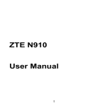
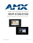
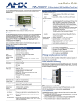
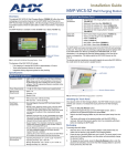
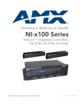
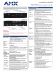
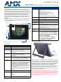
Installation Guide MVP-9000i Modero Wireless Touch Panel with Intercom Overview MVP-9000i Specifications (Cont.) The AMX MVP-9000i-XX Modero Wireless Touch Panel is a mobile device that communicates with a NetLinx Master via a standard 802.11a/b/g Wireless Access Point. Panel to panel communication is enabled via a full duplex VoIP intercom interface with SIP integration. The MVP-9000i utilizes a 9" Color Active LCD to display a 800 x 480 pixel image using over 16.7M colors, offers control via four programmable capacitive touch buttons and a capacitive touch directional pad in addition to its touch screen, and features programmable firmware that can be upgraded via the device’s mini-USB port. The MVP-9000i comes in black (MVP-9000i-GB, FG5967-01) and white (MVP-9000i-GW, FG5967-02). Screen Properties: For detailed installation, configuration, programming, file transfer, and operating instructions, refer to the MVP-9000i Operation/Reference Guide, available on-line at www.amx.com. Directional pad Capacitive touch buttons (4) Status LED Microphone Stylus MicroSD memory card slot Active Screen Area: • 7.75” x 7.40” (196.80 mm x 188.08 mm) • 9" (22.86 cm) diagonal Viewing Angle: • Up/Down/Left/Right: 85/85/85/85 Audio: • Mono speaker: 4 Ohm, 2 Watts 300Hz cutoff frequency Infrared Communication: • IR Transmit only, including AMX 38KHz, AMX 455KHz, and 3rd party IR. Operating/Storage Environments: • • • • • Included Accessories • PS3.0 Power Supply (FG423-30) • Stylus (pre-installed onto the left side of the device) Other AMX Equipment: • • • • • • • • • • Mini-USB connector DC power jack Docking Station interface connector Speaker • Screen resolution: 800 x 480 pixels (HV) @ 60 Hz refresh rate Aspect ratio: 16 x 9 Brightness (luminance): 400 cd/m2 Channel transparency: 8-bit Alpha blending Contrast ratio: 900:1 max. Display colors: 16.7M colors (24-bit color depth) Dot/pixel pitch: 0.246 mm Panel type: TFT Color Active-Matrix (IPS technology) • • • • • • • Operating Temperature: 0° C (32° F) to 40° C (104° F) Battery Charging Temperature: 0° C (32° F) to 30° C (86° F) Operating & Battery Charging Humidity: 20% to 85% RH Storage Temperature: -10° C (-14° F) to 60° C (140° F) Storage Humidity: 5% - 85% RH MVP-TDS-9-GB Black Table Docking Station (FG5967-10) MVP-TDS-9-GW White Table Docking Station (FG5967-11) MVP-WDS-9-GB Black Wall Docking Station (FG5967-12) MVP-WDS-9-GW White Wall Docking Station (FG5967-13) CC-MINIUSB Mini USB to PC Cable Adapter (FG5967-20) MicroSD card - 4GB (FG2116-81) MicroSD card - 8GB (FG2116-82) MVP-BP-9 Replacement Battery Pack (FG5967-21) PS-POE-AT High Power PoE Injector (FG423-81) MVP-STYLUS-52-XX Replacement Stylus, pack of 3 (Black: FG5966-21; White: FG5966-22) Connector Locations FIG. 1 MVP-9000i-GB Touch Panel components Stylus Specifications MVP-9000i Specifications (FG5967-01/02) Dimensions (HWD): • 7.62” x 10.98” x 1.06" (19.35 cm x 27.89 cm x 2.69 cm) Weight: • 3.60 lbs (1.63 kg) Power Requirement • Constant current draw: 1.1 A @ 12 VDC (without charging): • Startup current draw: 1.2 A @ 12 VDC • If panel is mounted onto a TDS or WDS, add 0.1 A to the above figures. Power Requirement Panel while charging battery: (while charging): • Constant current draw: 2.0 A @ 12VDC • If panel is mounted onto a TDS or WDS, add 0.1 A to the above figures. MiicroSD memory card slot Mini-USB port Kickstand DC power jack Minimum power supply required: • PS3.0 Power Supply (FG423-30) • PS-POE-AT High Power PoE Injector (FG423-81) through the Table Docking Station and Wall Docking Station FIG. 2 MVP-9000i-GW Kickstand View, showing connector locations Power Modes: • ON: All necessary modules are powered up and device remains online with the NetLinx Master. • ASLEEP: Only the backlight will be turned off after the user selectable time of inactivity has elapsed. Panel resumes the ON mode in ~ 1 second after being touched. • STANDBY: Power to all components other than the touch screen is turned off after the user selectable time of inactivity has elapsed. Device will turn back on by touching the screen. Re-acquiring a WAP connection may require up to 10 seconds. • SHUTDOWN: Power to all peripherals and components is turned off. The system remains in this mode until it is rebooted. With the unit facing you, the MicroSD card slot (for loading files such as photos), the mini-AB USB port (for programming and downloading firmware) and the DC power jack are located on the lower left side of the device. The connector for the Docking Stations is located on the bottom of the device. The MVP-9000i may be operated while docked in a Table Docking Station or Wall Docking Station, connected via the included power supply, or through battery power. The MVP-9000i supports an Ethernet over USB driver for panel downloads and firmware updates through its mini-USB port instead of through a standard Ethernet port. The mini-USB port may also be used, with an adaptor, with USB memory sticks and USB headphones. Battery Duration: • On: 5 hours; Sleep: 10 hours; Standby: 3 days Certifications: • • • • • Memory: • 4GB internal MicroSD (3.1GB accessible to user) FCC Class B CE IC VCCI C-Tick Warning: Although firmware upgrades can be done over wireless Ethernet; it is strongly recommended that firmware KIT files be transferred over a direct USB connection, or with the unit in the docking station using the wired ENET option, and only when the panel is connected to a power supply. If battery power or wireless connection fails during a firmware upgrade, the panel flash file system may become corrupted. Note: The mini-USB port cannot be used to power the device or charge the battery. Operation and charging must be done through the Docking Station connector or through the power jack. Setup Pages Connection Modes Mode Description Procedures Auto The device connects to the first master that responds. This setting requires that you set the System Number. Setting the System Number: 1. Select the System Number to open the keypad. 2. Set your Master System Number and select Ok. URL The device connects to the specific IP of a master via a TCP connection. This setting requires that you set the Master’s IP. Setting the Master IP: 1. Select the Master IP number to the keyboard. 2. Set your Master IP and select Ok. The panel is equipped with setup pages that allow you to set and configure various features on the panel. Consult the MVP-9000i Operation/Reference Guide for detailed information on the Setup pages. Accessing The Protected Setup Page 1. 2. 3. Press down and hold both the bottom left pushbutton and the directional pad (indicated in FIG. 1) simultaneously for 3-5 seconds. This opens the Setup page. Press the Protected Setup button on the Setup page. This opens a password keypad. Enter the panel password into the keypad (the default is 1988) and select Ok to access the Protected Setup page. Listen The device "listens" for the master to initiate contact. This setting requires you provide the master with the device’s IP. Setting the Panel’s Device Number and Device Name 4. In the Protected Setup page: 1. 2. 3. 4. Press the Device Number field to open the Device Number keypad. Enter a unique Device Number assignment for the panel and press OK. Press the Device Name field to open the Device Name keypad. Enter a unique Device Name assignment for the panel and press OK. Configuring the Panel’s Wireless IP Settings The first step is to configure the wireless communication parameters. This only configures the card to communicate with a target WAP, and it is still necessary to tell the panel which Master it should be communicating with; see Master Connection for more information. Consult the MVP-9000i Modero ViewPoint Touch Panels Operation/Reference Guide for setting the wireless communication using a static IP address. 5. Confirm device IP is on the Master URL list. You can set the Host Name on the device and use it to locate the device on the master. Host Name is particularly useful in the DHCP scenario where the IP address can change. Select the Master Port Number to open the keypad and change this value. The default setting for the port is 1319. Press Ok when finished. Set your Master Port and select Ok. If you have enabled password security on your master, you need to set the username and password within the device. 6. 7. 8. 9. 10. 11. Select the blank field Username to open the keyboard. Set your Username and select Ok. Select the blank field Password to open the keyboard. Set your Master Password and select Ok. Press the Back button twice to return to the Status page. Press the Reboot button to reboot the device and confirm changes. Touch Panel Calibration Wireless Communication Using a DHCP Address In the Protected Setup page, follow these steps: In the Protected Setup page: 1. 2. 1. 2. Select the Network button to open the System Settings page and select the WiFi tab. Toggle the DHCP/Static field until the choice cycles to DHCP. This action causes all fields in the WiFi tab (other than Host Name) to be greyed-out. Consult the MVP-9000i Operation/Reference Guide for setting a Host Name. Configuring the Card’s Wireless Settings This section configures both the communication and security parameters from the internal wireless card to the WAP. Once you have set up the wireless card parameters, you must configure the communication parameters for the target Master; see Master Connection for more information. Consult the MVP-9000i Operation/Reference Guide for configuring the wireless card for unsecured access to the WAP. Configuring The Wireless Card for Secured Access To the WAP In the Protected Setup page: 1. 2. 3. 4. 5. Select the Network button to open the System Settings page. Select the WiFi tab and press the Next button at the bottom of the page. Enter the SSID information automatically by pressing the Site Survey button. Select a secured WAP from within the Wireless Site Survey page, and press the Connect button. Write down the SSID name, Current Key string value, and panel MAC Address information so you can later enter it into the appropriate WAP dialog fields in order to "sync-up" the secure connection. These values must be identically reproduced on the target WAP. Consult the MVP-9000i Operation/Reference Guide for manually entering the SSID information. Master Connection The panel requires you establish the type of connection you want to make between it and your master. In the Protected Setup page: 1. 2. 3. Select the Network button to open the System Settings page. Select the Master tab. Press the listed Mode to toggle through the available connection modes. Select the Calibrate icon. Touch each target on the screen as they appear. Once calibrated, the panel confirms and instructs you to touch the screen to continue. Panel Intercom Configuration To incorporate an intercom-capable panel into your NetLinx system, download the module for the intercom panel from www.amx.com, and include it in your NetLinx project file. For searching purposes, the module manufacturer is AMX and the model is Intercom. Note: The intercom module will only work with AMX intercom-capable panels. Battery Life and Replacement The battery powering the MVP-9000i is designed for upwards of 300 deep discharge rechargings, which can supply 2 to 3 years of regular use. The device should be stored in either a Table Docking Station or Wall Docking Station when not in use to keep it at an optimum charge. The battery has reached its effective end of life after it can no longer hold more than a 70 percent charge. Proper Battery Maintenance NOTE: To insure maximum performance and reliability of your AMX Wireless Touch Panel, please insure that a full charge is performed every 3 months if not used regularly. If a battery is left uncharged beyond this time frame, it may result in premature battery lifespan degradation and will require replacement. NOTE: Charging Lithium Polymer batteries at high temperature will reduce the battery life. Industry guidelines dictate that batteries should not be charged at temperatures above 45° C (113° F). The temperature is determined by a combination of the ambient temperature where the panel is located, plus temperature increases normally occurring inside electronic devices containing batteries. AMX has implemented battery temperature monitoring features to maximize the rate of battery charging, while staying within industry temperature guidelines. Battery charge times will increase in installations where the room temperature is above 25° C (77° F), and may be temporarily suspended at room temperatures above 30° C (86° F). Battery charging will automatically resume once the temperature has fallen to appropriate levels. Minimizing the display backlight intensity and turning off the backlight during periods of non-use will also yield faster charge times. For full warranty information, refer to the AMX Instruction Manual(s) associated with your Product(s). 2/12 ©2012 AMX. All rights reserved. AMX and the AMX logo are registered trademarks of AMX. AMX reserves the right to alter specifications without notice at any time. 3000 RESEARCH DRIVE, RICHARDSON, TX 75082 • 800.222.0193 • fax 469.624.7153 • technical support 800.932.6993 • www.amx.com 93-5967-01 REV: C