1
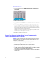
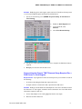
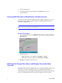
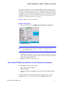
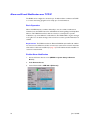
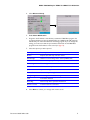
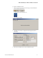
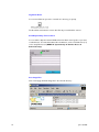
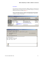
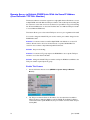
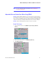
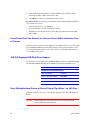
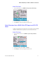
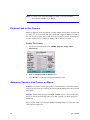
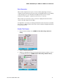
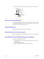
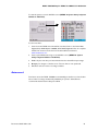
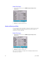
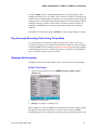
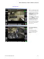
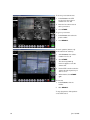
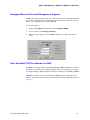
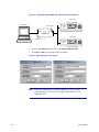
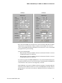
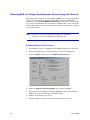
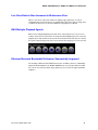
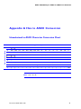
DVMS 1600/800 Duplex
DVMS V2.0 RAS V3.50
Addendum
DVMS 1600/800 Duplex DVMS V2.0 RAS V3.50 Addendum
DVMS Duplex 1600/800 Addendum
This addendum describes new features and options available for DVMS 1600/800 Duplex
embedded firmware version 2.0 and Remote Access Software (RAS) version 3.50.
Note
The DVMS 1600/800 Duplex recorder is referred to as the DVMS
1600/800 throughout this Addendum.
33 DVMS Duplex V2.0 and RAS 3.50 New Features
5 Point-of-Sale Interfacing New Features
Wayne (Dresser) Nucleus® Point-of-Sale (POS) server cash register interface
Generic cash register interface
Configurable incoming POS text size
POS text port escape filter added
More POS devices
18 V2.0 New Features
Single CD for authorities
Alarm and e-mail notification over TCP/IP
Single network IP address for multiple DVMS units
Adjustable Ethernet packet size
Simultaneous live local and live remote viewing
Document 900.0118 Rev 6.00
1
18 V2.0 New Features
200/250 GB IDE drive support
Configurable auto delete
Kalatal® Cyberdome and VCL PTZ support in addition to Vortex and Pelco D
Playback lock to one camera
Automatic switch to live camera on alarm
Administrator password recovery
Playback modifications
Record indicator on front panel enhanced
Add / replace disk drive without having to reformat all drives
Auto record after 60 seconds
Timelapse search options - Autobreak hourly and daily
Play currently recording video in Turbo mode
Autoplay enhanced
9 RAS 3.50 New Features
Multiple RAS user access
RAS compatible with multiple Silent Witness products
PTZ support
Remote password management
Configurable TCP port number
Speed up live images per second
Increased refresh rate in live multiscreen view
RAS multiple playback speeds
Ethernet network bandwidth utilization improved
2
June 10, 2003
DVMS 1600/800 Duplex DVMS V2.0 RAS V3.50 Addendum
5 New Text Insertion and POS Features
Silent Witness continues to focus on being an industry leader in text insertion and
point-of-sale interfacing. The following new features allow our customers to excel in this
area:
Point-of-Sale Interfacing
Wayne (Dresser) Nucleus® Point-of-Sale (POS)
server cash register interface added
Generic cash register interface added
Configurable incoming POS text size
POS text port escape filter added
More POS devices added
Wayne (Dresser) Nucleus Point-of-Sale Server Cash Register Interface
A cash register interface option has been added to store separate transaction data from
up to four cash registers on a single Wayne Nucleus Base 8 Point-of-Sale (POS) server.
Note
For a complete interface procedure, contact [email protected].
Basic Operation
The Wayne Nucleus POS server has a security camera interface option. When the
security camera interface is enabled, the transaction data from all indoor payment
terminals will be sent out over a single RS232C serial port. This data is sent out in real
time and can be mixed with other indoor payment terminal data. This single serial port is
connected to text insertion port number one only on the DVMS 1600/800. By enabling
the Cash Register Option for NU00008-1, the DVMS will separate the transaction data
for individual indoor payment terminals and store the data with a specific live camera video
as specified by the user.
Document 900.0118 Rev 6.00
3
Enable This Feature
1.
Access the Text Parsing screen (MENU ➤ System Setup ➤ Text Ports ➤
Text Parsing).
2.
Enable the Cash Register field.
3.
In the Type field, select NU00008-1 for the Wayne (Dresser) Nucleus Base 8 POS
server.
4.
In the Terminal Mapping area, set a specific port to capture the transaction data
from the individual indoor payment terminals (cash registers). Typically the indoor
payment terminals start at number 2. Number 2 is usually the busiest cash register.
In the screen shot above, port 1 has been set to collect transaction data from indoor
payment terminal 2 and indoor payment terminal 3.
Typically, most convenience stores have two cash registers. It is possible to collect
data from up to four cash registers on one server.
5.
Accept your changes and exit this screen.
Generic Cash Register Interface Allows On-site Programming for
Various Cash Registers and POS Servers
Situation You have a POS text insertion opportunity but must be able to interface to
customers’ POS server or cash register. The problem is that the POS server or cash
register does one of the following:
•
Sends out transaction data with unique start and stop characters
•
Does not use carriage return line feed to end transactions
•
Mixes all transaction data and sends it out one common serial port.
Requirements The following is required to successfully use this feature:
4
•
The data output of the POS device is RS232C, ASCII data or the data from the POS
device must be converted to RS232C, ASCII formatted data.
•
The transaction data must be sent out in real time to record a live camera with the
transaction text.
June 10, 2003
DVMS 1600/800 Duplex DVMS V2.0 RAS V3.50 Addendum
Solution Enable the generic cash register option and use the Text Protocol Setup screen
to set how the DVMS deciphers the data from the POS device.
1.
Access the Text Parsing screen (MENU ➤ System Setup ➤ Text Ports ➤
Text Parsing).
2.
Enable the Cash Register field.
3.
In the Type field, select
Generic.
4.
Select Text Protocol Setup.
5.
Set options on the Text Protocol Setup screen to decipher the POS device data as
required.
6.
Accept your selections and exit this screen.
Determining the Generic TEXT Protocol Setup Required For a
POS Server or Cash Register
Requirements To program the Text Protocol Setup screen you need either or both of
the following:
•
A document describing the POS data output and format
•
A sample collection of transaction data output from the POS server
Solution Ideally you should obtain an actual sample trace of a series of transactions from
the POS server or cash register. Sometimes the documentation does not include all the
information required. In this case:
1.
Insert a data analyzer or PC running Hyperterminal on the output.
2.
Generate several transactions.
Document 900.0118 Rev 6.00
5
3.
Collect the data in a file.
4.
E-mail this information to Silent Witness at [email protected] for
recommendations.
Incoming POS Text Size on Main Monitor Can Be Increased
You can now increase the incoming POS text data to display in a large font size on the
main video monitor, making it easier to read. You can also adjust the text size for
multi-camera display mode.
Note
This does not affect the camera title size.
Enable This Feature
1.
Access the Main Monitor screen (MENU ➤ System Setup ➤ Display Setup ➤
Main Monitor).
2.
Set the text size for:
3.
•
Single camera view (1 x 1). Options are NORMAL or LARGE.
•
Multi-camera view (2 x 2). Options are HALFSIZE or NORMAL.
Accept your changes and exit this screen.
POS Text Port Escape Filter Stores and Displays Transaction Data
Correctly
Situation POS transaction data displays all over the video. Many POS cash registers send
their transaction data out an RS232C serial port using ASCII formatted data to a
transaction printer. Some cash registers include special control characters that cause the
printer to print different parts of the transaction in different font sizes and styles.
6
June 10, 2003
DVMS 1600/800 Duplex DVMS V2.0 RAS V3.50 Addendum
To capture this data and store it in the DVMS 1600/800 a Y cable is typically inserted
between the cash register and the printer. This Y cable parallels off the transmit data line
and signal ground line only. These two lines are connected to the DVMS text insertion
port number one (Pin 14 TXD, Pin 13 GND). When the data is collected by the DVMS
1600/800 it may not line up correctly on the monitor as the control characters cause
carriage returns and line feeds at incorrect locations.
Solution Enable the text port escape filter.
Enable This Feature
1.
Access the Text Ports screen (MENU ➤ System Setup ➤ Text Ports).
2.
Enable Escape Filter.
Note
If the Escape Filter box is grayed out, disable the Cash Register field in
the Text Parsing screen.
By enabling the escape filter, the control characters for the different font sizes and
styles will be deleted, leaving only the transaction data with carriage returns and line
feeds occurring where they should.
3.
Accept your changes and exit this screen.
Three More POS Devices Added to List of Successful Installations
The following POS devices have been added:
•
Wayne (Dresser) Nucleus® Base 8
•
Gilbarco G-SITE®
•
Panasonic® Keystation with RS232C interface board to TM311 Epson® thermal
printer
For additional information regarding interfacing to any of these devices, contact
[email protected] or the text insertion team at [email protected].
Document 900.0118 Rev 6.00
7
18 New Features in V2.0
18 new features have been added in V2.0.
DVMS V2.0
Single CD for authorities
Alarm and e-mail notification over TCP/IP
Single IP address for multiple DVMS units
Adjustable Ethernet packet size
Simultaneous live and remote viewing
200/250 GB IDE drive support
Configurable auto delete
Kalatal® Cyberdome and VCL PTZ support in addition to Vortex and Pelco D
Playback lock to one camera
Automatic switch to live camera on alarm
Administrator password recovery
Playback modifications
Record indicator on front panel enhanced
Add / replace disk drive without having to reformat all drives
Auto record after 60 seconds
Timelapse search options - Autobreak hourly and daily
Play currently recording video in Turbo mode
Autoplay enhanced
8
June 10, 2003
DVMS 1600/800 Duplex DVMS V2.0 RAS V3.50 Addendum
Single CD for Authorities Includes Viewer and Incident Video Clips
For DVMS 1600/800 Duplex units that have the optional CD R/W installed, you can now
burn a single CD with video clips of an incident plus a RAM resident RAS Viewer
application. This CD can be given to a viewing authority for fast response to an incident.
Situation An incident occurs and you need to give a copy of the video to the viewing
authorities for playback purposes as quickly as possible.
Solution
1.
From your DVMS with the optional CD R/W installed, you search and find the video
of the incident.
2.
Burn a single CD disc with the relevant incident video clips, along with the Viewer
software needed by the viewing authority. Total time is less than 30 minutes.
3.
Give this single Evidence CD to the authorities.
You can burn additional copies as required.
Basic Operation
When you create an Evidence CD disc, the RAS Viewer utility is burned to the same CD
as the video clips you need to give to the authorities.
The authorities then take the Evidence CD and insert it into their PC and launch the RAS
Viewer application contained on the CD. This utility launches into RAM on the PC and
does not require being copied onto the PC. This method satisfies requirements where files
are not allowed to be loaded onto the authority’s PC hard drive. Authorities use the RAS
Viewer application to play back any of the clips stored on the same CD disc.
The RAS Viewer is compatible with the Windows® FAT32 format and NTFS format,
making it highly likely that it will execute on almost all PCs with Windows operating
systems.
Document 900.0118 Rev 6.00
9
Alarm and E-mail Notification over TCP/IP
The DVMS can be configured to forward up to 12 different alarm conditions via TCP/IP
to a remote monitoring program and to notify up to 5 e-mail addresses.
Basic Operation
When the DVMS detects a condition defined by a user, the condition notification is
forwarded over the TCP/IP network to an E-Mail Net monitoring utility provided by Silent
Witness. The E-Mail Net interfaces with the customer’s e-mail system to provide
notification to up to five different e-mail addresses. The DVMS will also log the messages
in a log file. You can attach an image of the event from a camera, provided this feature is
enabled.
Requirements The DVMS must have an Ethernet PCMCIA card installed, be enabled
for remote access via Ethernet, and be connected to a network. The customer must have
a PC with an e-mail service installed (see page 12). The E-mail Net must be installed on a
customer’s networked PC.
Enable Alarm Notification
10
1.
Access the Remote Access screen (MENU ➤ System Setup ➤ Remote
Access).
2.
Enable Remote Access.
3.
Set the Method field to IEEE 802.3 (Ethernet).
June 10, 2003
DVMS 1600/800 Duplex DVMS V2.0 RAS V3.50 Addendum
4.
Select Advanced Setup.
5.
Enable Alarm Notification.
6.
Program in the IP Address of the PC that contains the E-Mail Alert program. It is
recommended that you have the default TCP port of 44446 as this will match the
default TCP port of the Silent Witness monitoring program. If you do change this
setting, you must ensure that the port numbers match both in the E-Mail Alert
program and in the IP address on this screen (see page 13).
7.
Select the options you wish reported.
Field option
Description
Motion
Reports start and stop of motion events
Attach Image
Attaches a camera image of the event in JPEG format.
Drive full
If disk drive capacity for timelapse or event is full
Time changed
Time changed
Alarm
Alarm start or stop detected for alarm events
System error
System error type and number
Power UP
Unit has had power applied
Config changed
Unit configuration has been changed
Text
Text event detected
Recording
Start or stop due to operator intervention
Remote connect
A remote user has connected.
8.
Document 900.0118 Rev 6.00
Select Done to activate your changes and exit this screen.
11
Install and Configure the E-Mail Alert Program
Requirements
•
Permanently open E-mail application, either:
•
Microsoft Outlook™ 2002
•
Microsoft Outlook™ 2000
•
Microsoft Outlook™97
Note
If the E-mail application is not open, e-mail alerts will not be forwarded.
When opened, if e-mail alerts were previously enabled, multiple
messages will be forwarded at that time.
•
Permanent network connection to the DVMS units you will monitor from your PC
•
PC running one of the following Windows operating systems:
•
•
Windows® 98, Second Edition
•
Windows NT® 4.0, Service Pack 6a or higher
•
Windows® 2000, Service Pack 2 or higher
•
Windows ®XP Professional
DVMS with alarm notification enabled
After you run the setup program and install the E-Mail Alert application, this application
will be added into the PC Start Menu. The next time the PC restarts, it will automatically
start the E-Mail Alert program. The user will see the E-Mail Alert splash screen for a
couple of seconds and then the program will minimize to the Windows status bar area
located on the lower right corner.
The setup program can be found on the CD that came with the DVMS 1600/800 unit in
the E-Mail Alert 1.0 folder. You can also find the setup program on the Silent Witness web
site at www.silentwitness.com.
To install the E-Mail Alert program:
12
1.
Insert your RAS CD into a Windows based PC that has a CD-ROM drive.
2.
When the RAS auto install window displays, click Cancel, and then Finish to exit.
3.
Using Windows Explorer, navigate to the E-Mail Alert folder, and then click
Setup.exe.
4.
Follow the prompts as required.
June 10, 2003
DVMS 1600/800 Duplex DVMS V2.0 RAS V3.50 Addendum
To configure the E-Mail Alert program:
1.
Maximize the E-Mail Alert program by double-clicking the minimized E-Mail Alert
icon in the Windows status bar area
or double-click the Desktop E-Mail Alert icon
The following screen displays.
2.
Click Setup on the menu bar to configure the monitoring program options as
shown below.
3.
When finished, click Save, and then miniize the E-Mail Alert program.
Document 900.0118 Rev 6.00
13
Log Alarm Event
You can save all alarms reported to a text file in a directory you specify.
The file will be saved with the current date. Each day a new file will be created.
Send Report Daily / Time to Send
You can define a daily time that the DVMS will send an Alarm event log file to up to three
e-mail addresses. To forward immediate alarm notifications, set the e-mail addresses (1-5)
on the Setup Email screen (MENU ➤ System Setup ➤ Remote Access ➤
Advanced Setup).
Save Image Files
Save received jpeg thumbnail image files in the selected directory.
14
June 10, 2003
DVMS 1600/800 Duplex DVMS V2.0 RAS V3.50 Addendum
Server Port
The server port is the TCP port where alarm notification packets are received from the
DVMS. This TCP port must match the port set in the Advanced Setup screen. The factory
default sets both of these to 44446 (see page 11).
After you enable alarm monitoring, the alarm monitoring program forwards messages
received to the e-mail recipients you defined on the DVMS. Examples of typical alarm
notification messages are shown below.
Document 900.0118 Rev 6.00
15
Remote Access to Multiple DVMS Units With the Same IP Address
(User Definable TCP Port Number)
This feature addresses customers request for a single public Internet IP address to access
multiple DVMS units with different TCP port numbers. This is called port forwarding. On
the customer’s router that connects to the Internet, it is possible to set a port forwarding
list. All external RAS users use the same IP address but use a different TCP port number
to access different DVMS units.
This feature allows you to select which TCP ports can cross your organization’s firewall.
You can also change the default TCP port used to match a port number changed on the
DVMS RAS as well.
Situation A customer wants to install multiple DVMS units behind one common IP
address. All units need to be access via the Internet or a private WAN/LAN. The
customer does not want to buy additional public IP addresses.
Solution Use port forwarding.
Situation A customer’s IT group requires the DVMS RAS to use a specific TCP port
number to cross their Internet firewall.
Solution Change the default TCP port number used by the DVMS unit and RAS to the
TCP port number required by the IT group.
Enable This Feature
16
1.
Access the Remote Access screen (MENU ➤ System Setup ➤Remote
Access).
2.
The TCP port number follows the IP Address. You can adjust this from 4096 to
65536. The factory default is 44442 for both the DVMS unit and RAS. For RAS to
communicate with a specific DVMS unit, the port number used must match the port
used by RAS.
June 10, 2003
DVMS 1600/800 Duplex DVMS V2.0 RAS V3.50 Addendum
Note
For a more detailed description of this feature, see User Definable TCP
Port Number for RAS, page 31.
Adjustable Ethernet Packet Sizes When Using PPPoE
Situation When a DVMS is installed for access over the Internet, the Internet Service
Provider (ISP) connection uses Point to Point Protocol over Ethernet (PPPoE). When RAS
tries to connect to the DVMS, the Login screen appears but after log in the DVMS never
responds. The ISP may be restricting the Ethernet packet sizes to less than 1500 bytes.
Solution Reduce the PPPoE packet size until the connection is successful.
Enable This Feature
1.
Access the Remote Access screen (MENU ➤ System Setup ➤Remote
Access).
2.
Ensure that the Method field is set to IEEE 802.3 (Ethernet).
3.
Select Advanced Setup.
Document 900.0118 Rev 6.00
17
4.
Set the PPPoE Packet Size field to less than 1500 bytes. The packet size can be
adjusted from 900 to 1500, in increments of 100.
5.
Select Done to activate your changes and exit this screen.
Recommendation If necessary to use this feature and to obtain the highest possible use
of your network resources:
•
Set the packet size low—say 1000 bytes
•
Connect with RAS to ensure the connection works
•
Gradually increase the packet size to get the largest possible packet size that will
work reliably
Front Panel User Can Select Live Camera Views While a Remote User
is Present
Previous to V2.0, if a remote user was logged in to the DVMS, another user could not dial
in to the DVMS via RAS. Now, front panel operation can be performed while a remote
user is present; thus allowing live camera view selection of individual camera views, 4, 9,
or 16 multiple camera views.
200/250 Gigabyte IDE Disk Drive Support
As of V2.0, you can now install 200 or 250 Gbyte IDE disk drives in your DVMS 1600/800
unit. 200 and 250 Gbyte IDE disk drives officially recognized by Silent Witness are:
IDE disk drive make
Model
200 GB Drives (SWE #140.0084)
Maxtor® 200 GB
6Y200PO
Western Digital® 200 GB
WD2000JB
250 GB Drives (SWE #140.0085)
Maxtor® 250 GB
4A250J0
User Definable Auto Delete of Stored Video Clips After 1 to 365 Days
This feature addresses the needs of the 30-day privacy law in the United Kingdom and
Europe.
Caution
18
When enabled, video clips older than the time period specified will
be inaccessible after that time frame.
June 10, 2003
DVMS 1600/800 Duplex DVMS V2.0 RAS V3.50 Addendum
Enable This Feature
1.
Access the Disk Setup screen (MENU ➤ Storage Setup ➤Disk Setup).
2.
Enable Auto Delete and set the days field to 30.
3.
Select Accept to confirm your changes and exit this screen.
Kalatel Cyberdome Series, RS485 2-Wire PTZ Support and VCL PTZ
Added
In addition to Silent Witness Vortex and Pelco D, it is now possible to interface the DVMS
1600/800 to Kalatel® Cyberdome pan/tilt/zoom cameras and VCL PTZ cameras.
Enable This Feature
1.
Access the Remote Access screen (MENU ➤ System Setup ➤Remote
Access).
2.
Set the Dome Address field to Cam 1, 1, Kalatel.
3.
Select Accept to confirm your changes and exit this screen.
Document 900.0118 Rev 6.00
19
Note
For dome control from the DVMS front panel or remotely from RAS,
ensure that the DVMS is set as “Master.”
Playback Lock to One Camera
When you play back a video clip that has recorded multiple cameras at the same time and
you select one camera to review and then press the left or right arrow button to jump to
the next or previous video clip, you will stay locked on that one camera. Previously the
monitor would revert to a multiscreen display of all the cameras recorded.
Enable This Feature
1.
Access the User Preferences screen (MENU ➤ System Setup ➤User
Preferences).
2.
Enable the Playback Lock to Camera field.
3.
Select Accept to confirm your changes and exit this screen.
Automatic Switch to Live Camera on Alarm
Situation You want to install a panic button in a subway station so that when the panic
button is pressed a remote monitoring system automatically displays a live camera view of
the location.
Solution Activate alarm homing in the DVMS 1600/800 and run a wire from the panic
button to the remote monitoring station to provide a ground to an alarm input of the
DVMS unit.
When the panic button is pressed, the DVMS automatically switches to a live view of the
camera monitoring the area.
20
June 10, 2003
DVMS 1600/800 Duplex DVMS V2.0 RAS V3.50 Addendum
Basic Operation
When an alarm input detects an open or closed condition (depending on how you
configure the alarm input) the main video monitor automatically switches to a live display
of the camera(s) set to record the alarm. If multiple cameras are set to record a
multicamera screen appears—quad (4 x 4), nine (3 x 3), or 16 (4 x 4).
When an alarm is removed, the monitor continues to display the alarm view until an
operator manually changes the live display.
If a single alarm occurs and you are viewing the first alarm camera view and a second alarm
then occurs on a different camera, the monitor shows a multiscreen display that includes
both alarming cameras.
Enable This Feature
1.
Access the General Setup screen (MENU ➤ Event Recording ➤General
Setup).
2.
Enable the Alarm homing field.
3.
Enable the individual alarm inputs and program which cameras you want to record
on the Alarm Events screen (MENU ➤ Event Recording ➤Alarm Events).
Document 900.0118 Rev 6.00
21
4.
Connect the panic button to the appropriate alarm input based on the following:
Alarm Inputs
To set NO/NC, see Alarms.
+5 VDC
10K
Normally Closed (NC).
If open, alarm is
detected.
Normally open (NO).
If closed, alarm is
detected.
Detector
Internal to Duplex
External to Duplex
(Add this functionality
yourself)
Administrator Password Recovery
In the event that the Administrator password has been forgotten and you cannot log on
to your DVMS 1600/800, it is now possible to contact Silent Witness Technical Support
for help in recovering the Administrator password.
Playback Modifications
Additional playback speeds have been added to the jog wheel.
Record Indicator on Front Panel Improved
When recording is enabled, a moving * (asterisk) moves left to right on the LCD display.
Add / Replace Disk Drive Without Having to Format All Disks
V2.0 features a new utility that allow you to:
22
•
Add further drives for increased storage capacity while preserving video stored on
the original drive(s)
•
Re-partition an individual disk drive
•
Replace a single faulty drive without affecting other disk drives
June 10, 2003
DVMS 1600/800 Duplex DVMS V2.0 RAS V3.50 Addendum
To view this option, access the Add Disk screen (MENU ➤ System Setup ➤System
Utilities ➤ Add Disk).
To add a new drive:
1.
Power down the DVMS unit and install the new drive. Refer to the Internal Drive
Upgrade Kit for DVMS Duplex 1600/800 (DV16/8-DUK) Application Note for complete
details. This document can be found on the Silent Witness web site at
www.silentwitness.com.
2.
Power up the DVMS unit and go to the Add Disk screen (MENU ➤ System
Setup ➤System Utilities ➤ Add Disk).
3.
Enable only the new drive you have added and set the desired Event percentage.
4.
Accept your changes to exit this screen. The new drive is now operational.
5.
Exit Menu mode and ensure recording is enabled.
Autorecord
This feature causes the DVMS 1600/800 to automatically put itself in record mode after
60 seconds if recording is inadvertently disabled by an operator. Silent Witness
recommends that this feature always be enabled.
Document 900.0118 Rev 6.00
23
Enable This Feature
1.
Access the User Preferences screen (MENU ➤ System Setup ➤ User
Preferences).
2.
Set the Auto record field to Enabled.
3.
Accept your changes and exit this screen.
Autobreak Hourly and Daily
To ease searching for incidents in timelapse recording mode, single video clip size options
of hourly and daily have been added. Previously the choices were 15 minutes or no
autobreak (one continuous single clip).
Enable This Feature
1.
Access the User Preferences screen (MENU ➤ System Setup ➤ User
Preferences).
2.
Set the Autobreak field to Daily or Hourly.
3.
Accept your changes to exit this screen.
When selected, the DVMS stores timelapse video in individually searchable chunks of
video based on your selection.
24
June 10, 2003
DVMS 1600/800 Duplex DVMS V2.0 RAS V3.50 Addendum
A setting of Daily creates a single daily timelapse clip for each day starting at 12:00
midnight. This allows you to do a simple search for incidences based on a particular day.
Instead of jump searching multiple 15-minute portions of hourly clips (as with the Hourly
setting) a user can scan through a single day clip using turbo mode on the jog wheel. When
viewing an incident, a reviewer can slow down and view the incident as required. If
archiving to a CD-ROM disc is necessary, perform a partial clip archive of the time
required.
Silent Witness recommends a setting of Hourly for systems doing timelapse recording.
Play Currently Recording Video Using Turbo Mode
It is now possible to press PLAY and rotate the jog wheel into turbo mode to view
currently recording video up to within five minutes of the current time. If the Autobreak
interval in a DVMS unit is set to Daily (see Autobreak Hourly and Daily), the review will begin
at 12:00 midnight and you can use turbo fast forward to review all recorded timelapse
video to within five minutes of the current time.
Autoplay Enhancements
Autoplay enhancements have been added to allow easier review when selecting PLAY.
Enable This Feature
1.
Access the User Preferences screen (MENU ➤ System Setup ➤ User
Preferences).
2.
Enable the Auto play field.
3.
Accept your changes to exit this screen.
When enabled, you can put the DVMS into fast forward turbo mode to advance rapidly
through the selected video clip. When the end of the clip is reached, the DVMS
automatically jumps to the next clip and continues reviewing in turbo fast forward mode
Document 900.0118 Rev 6.00
25
without adjusting the jog wheel. This enables you to continuously review all timelapse clips
without jog wheel adjustment. If the DVMS was set for hourly autobreak intervals, you can
scan the entire day into the previous day or for as long as you like.
Note
This feature works best if you enable Playback Lock to One Camera
(see Playback Lock to One Camera).
Note
To jump to a previous clip (User Preferences screen, Clip order field is
set to Chronological), press the
button.
9 RAS V3.50 Feature Additions
The following nine new features were added in RAS V3.50:
RAS V3.50 Features
Multiple RAS user access
RAS compatible with multiple Silent Witness
products
PTZ support
Remote password management
Configurable TCP port number
Speed up live images per second
Increased refresh rate in live multiscreen view
RAS multiple playback speeds
Ethernet network bandwidth utilization improved
Multiple RAS Users
Up to three different PCs with RAS can connect to the same DVMS 1600/800 unit
simultaneously. All three can perform live camera view operations at the same time but
only one can perform system searches or system configuration at a time. No additional
programming is required for this functionality.
26
June 10, 2003
DVMS 1600/800 Duplex DVMS V2.0 RAS V3.50 Addendum
If a local front panel user has entered the configuration menus, no RAS users can log in to
the DVMS unit. Also, if a RAS user has logged in to the DVMS, the local front panel user
can only perform live camera views, the local user cannot perform searches, play back,
configuration changes or reports while at least one remote user is connected.
Three remote users can connect simultaneously, in addition to one front panel local user.
All can perform live camera viewing, including the same camera simultaneously but only
one can do configurations or searches.
RAS Compatible With Multiple Silent Witness Products
A single RAS software package is now compatible with the following Silent Witness
products.
Product
Product software version
compatible with RAS 3.5
Notes
DVMS 1600/800
Duplex
2.0
Configuration files in DVMS 2.0 and later are
encrypted and not compatible with previous
versions.
DVMS
1600/800/400/100
Simplex
1.01G
Some new RAS features to be implemented in a
future release of Simplex software, including:
DVMS 100
2.4
•
•
Multiple playback speeds
Ethernet TCP/IP bandwidth utilization
enhancements
Some new RAS features not currently
implemented, including:
•
•
Multiple playback speeds
Ethernet TCP/IP bandwidth utilization
enhancements
Pan Tilt Zoom (PTZ) Camera Support By RAS
Remote control of PTZ cameras connected to a DVMS 1600/800 is now possible with
RAS for the following cameras:
•
Silent Witness Vortex
•
Pelco® D
•
Kalatel® Cyberdome
Document 900.0118 Rev 6.00
27
Requirements
DVMS 1600/800 running V2.0 and later firmware
28
•
RAS V3.50 or later
•
The PTZ camera must be connected directly to a DVMS 1600/800
•
The DVMS must be enabled for PTZ control in the Remote Access menu.
June 10, 2003
DVMS 1600/800 Duplex DVMS V2.0 RAS V3.50 Addendum
Basic Operation
1.
Click on an individual live camera
view to select it for PTZ control.
2.
In the PTZ Control area, select
Preset, a number from 1 to 99,
then RECALL to go to a user
defined live camera view.
3.
Select Pattern, a number from 1
to 3, then RECALL to execute a
user programmed live camera
view pattern. This feature only
works with Vortex cameras.
4.
Use the controls to move the live
camera view as required and to
zoom in and out.
A red outline indicates the
current camera is selected for
PTZ control.
You can still use the PTZ
controls in multiscreen mode
for the selected live PTZ
camera.
Document 900.0118 Rev 6.00
29
To store a preset camera view:
1.
Select Preset in the PTZ
Control area, then select a
number from 1 to 99.
2.
Move the live camera view to
where you want it.
3.
Click STORE.
To go to a preset view:
1.
Select Preset, then select the
preset number.
2.
Click RECALL.
To store a pattern (feature only
works with Vortex cameras):
1.
Select Pattern, then select a
number from 1 to 3.
2.
Click STORE.
The text Programming
Pattern appears on the live
camera view.
3.
Use the PTZ controls to take the
camera through the pattern you
wish to store.
4.
When finished, click STORE
again.
To execute:
1.
Select Pattern, then the
number.
2.
Click RECALL.
To stop the pattern, click anywhere
on the PTZ control.
30
June 10, 2003
DVMS 1600/800 Duplex DVMS V2.0 RAS V3.50 Addendum
Encrypted Remote Password Management Support
DVMS passwords and privilege levels can now be changed by a user with Administrative
access. The configurations are encrypted when passed across the network to and from
RAS to ensure that passwords remain confidential.
To access this feature:
1.
From the RAS Setup pull-down menu, select Configure DVMS.
2.
Log on, and then select Change Password.
3.
Make the desired changes, then click OK to confirm your changes and exit the
screen.
User Definable TCP Port Number for RAS
Situation A customer wants to install multiple DVMS 1600/800 units behind a common
IP address. The customer’s IT department will use TCP port forwarding to accomplish
this. They will assign a different destination TCP port number for each DVMS 1600/800.
Solution For RAS to connect to these different DVMS units you must program the
different destination TCP port numbers in the Network Connection dialog box as shown
in Figure 3.
Document 900.0118 Rev 6.00
31
Figure 4 Sample Multiple DVMS Units, One Common IP Address
DVMS #1
192.168.1.223:44442
PC with RAS
192.168.1.254
DVMS
1600
Router/firewall
DVMS #2
205.24.56.173
DVMS
1600
192.168.1.224:44443
1.
From the RAS Setup pull-down menu, select Network Connection.
2.
Press Add or Edit to program the TCP port numbers.
Figure 3 Network Connection Screen
Note
32
The factory default TCP port number is 44442. If you do not require
port forwarding, you do not need to change the RAS TCP port or the
DVMS TCP port.
June 10, 2003
DVMS 1600/800 Duplex DVMS V2.0 RAS V3.50 Addendum
DVMS #1
DVMS #2
Both of the above DVMS units are behind the common IP address 205.24.56.173. What
separates them is the Destination TCP port number. In this example, the customer’s
router or firewall will be IP address 205.24.56.173. The Customer’s router or firewall will
be programmed for port forwarding.
In the port forwarding table:
•
When destination TCP port 44442 is detected, the destination IP will be converted
to DVMS #1 IP address 192.168.1.223.
•
When destination TCP port 44443 is detected, the destination IP will be converted
to DVMS #2 IP address 192.168.1.224.
You must also program the DVMS 1600/800 units to decode these TCP destination port
numbers in the Remote Access screen as shown above. The Gateway IP in the DVMS units
is the IP address of the customer’s internal gateway or firewall.
When DVMS #2 is connected to via RAS, it will send its packets to the gateway with the
destination IP of the RAS PC but with a source IP of the DVMS #2 of 192.168.1.224. The
gateway will then convert this source address to 205.24.56.173 before forwarding it on to
the RAS PC.
Document 900.0118 Rev 6.00
33
Reducing RAS Live Display Quality Speeds Up Live Images Per Second
RAS software now instructs the remote DVMS 1600/800 unit to send reduced data sized
images across the network if live display image quality is reduced in the RAS User
Preferences screen (Setup ➤ RAS User Preferences). This allows more live images
per second to be forwarded across the network to the RAS software. It also reduces the
time the RAS software needs to decompress the live images received because the images
are a smaller data size.
Note
This does not affect record quality at the DVMS unit. The DVMS
continues to record at its locally refined compression rate.
Enable and Observe This Feature
34
1.
Launch RAS and connect to a DVMS unit. Press Play to display a live camera view.
2.
Observe the fps (fields per second) and bytes per second on the RAS screen.
3.
From the Setup drop-down menu, select RAS User Preferences.
4.
Reduce the Display (live) Image Quality area, and then click Save.
5.
Stop live video and start again by clicking the Live button twice. This instructs the
DVMS to send reduced data images to the RAS software.
6.
Observe the fps and bytes per second.
7.
Change to multiscreen mode and observe the fps and bytes per second.
June 10, 2003
DVMS 1600/800 Duplex DVMS V2.0 RAS V3.50 Addendum
Live View Refresh Rate Increased in Multiscreen View
When a user selects a live view multiscreen display, image updates per second are
substantially improved. This has been accomplished by reducing the data per image when
a multiscreen view choice is selected in RAS. Record quality is not affected.
RAS Multiple Playback Speeds
RAS now has multiple playback speeds that can be selected by the user. An on-screen
indicator shows the user which is the currently selected fast playback speed. To select the
playback speed, click the fast forward or fast reverse button. Each time these are clicked,
the speed indicated changes. Choices are from 4 to 32 times images per second recorded.
Ethernet Network Bandwidth Utilization Substantially Improved
The handling of Ethernet LAN TCP/IP data has been modified to allow for substantially
higher bandwidth utilization. On DVMS 1600/800 units connected by an Ethernet LAN,
the remote user will notice faster image updates per second and see higher bandwidth
utilization.
Document 900.0118 Rev 6.00
35
36
June 10, 2003
DVMS 1600/800 Duplex DVMS V2.0 RAS V3.50 Addendum
Appendix A Hex to ASCII Conversion
Hexadecimal to ASCII Character Conversion Chart
Most Significant Byte
Least Significant Byte
0
1
2
3
4
5
6
7
8
9
A
B
C
D
E
F
0
NUL
SOH
STX
ETX
EOT
ENQ
ACK
BEL
BS
HT
LF
VT
FF
CR
SO
SI
1
DLE
DC1
DC2
DC3
DC4
NAK
SYN
ETB
CAN
EM
SUB
ESC
FS
GS
RS
US
2
SP
!
“
#
$
%
&
‘
(
)
*
+
,
-
.
/
3
0
1
2
3
4
5
6
7
8
9
:
;
<
=
>
?
4
@
A
B
C
D
E
F
G
H
I
J
K
L
M
N
O
5
P
Q
R
S
T
U
V
W
X
Y
Z
[
\
]
^
_
6
‘
a
b
c
d
e
f
g
h
i
j
k
l
m
n
o
7
p
q
r
s
t
u
v
w
x
y
z
{
|
}
~
DEL
Note
Document 900.0118 Rev 6.00
Hex = 20 = SP.
37
www.silentwitness.com
Toll free: 1.888.289.2288
International: 00800.2020.8080
Silent Witness Enterprises Ltd.
Sales:
1.888.289.2288
Tech Service:1.800.893.9513
Phone:
1.604.574.1526
Fax:
1.604.574.7736
Email:
[email protected]
6554 - 176th Street
Surrey, B.C. V3S 4G5
Canada
For the most current product and software download information,
visit www.silentwitness.com/support/.
Document 900.0118 Rev 6.00 June 10, 2003
Specifications subject to change without notice.
Imperial conversions are approximate.
Gyyr® and Silent Witness® are registered trademarks of Silent Witness Enterprises Ltd. ©2002 Silent Witness Enterprises Ltd. All rights reserved. Printed in Canada.