1
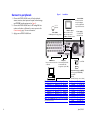
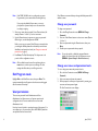
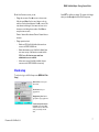
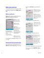
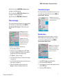
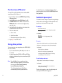
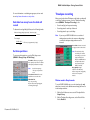
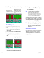
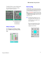
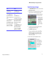
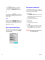
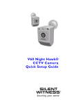
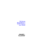
DVMS 1600/800 Duplex Getting Started Guide Warranty and service Important safeguards Read instructions Please read all the safety messages and the contents of this guide carefully before operating the unit. Safety Installation and servicing should be done by certified technicians to conform to all local codes and to maintain your warranty. RISK OF ELECTRIC SHOCK DO NOT OPEN CAUTION: TO REDUCE THE RISK OF ELECTRIC SHOCK, DO NOT REMOVE THE COVER. NO USER-SERVICEABLE PARTS INSIDE REFER SERVICING TO QUALIFIED SERVICE PERSONNEL Subject to the terms and conditions listed on the Product Warranty Card, during the warranty period Silent Witness will repair or replace, at its sole option, free of charge, any defective products returned prepaid. In the event you have a problem with any Silent Witness product, please call Customer Service for assistance or to request a Return Authorization (RA) number. In the U.S.A. and Canada, call 1.800.893.9513, or call +1.604.574.1523. This symbol indicates that dangerous voltage constituting a risk of electric shock is present within this unit. For international, call 00.800.2020.8080. This symbol indicates that important operating and maintenance instructions accompany this unit. Prior authorization must be obtained for all returns, exchanges, or credits. Items shipped to Silent Witness without a clearly identified Return Authorization (RA) number may be refused. WARNING! The DVMS 1600/800 is intended for indoor use. To reduce a risk of fire or electric shock, do not expose this product to rain or moisture. WARNING! This equipment complies with the limits for Class A digital device, pursuant to part 15 of the FCC rules. These limits are designed to provide reasonable protection against harmful interference when the equipment is operated in a commercial environment. This equipment generates, uses, and can radiate radio frequency energy and, if not installed and used in accordance with the instruction manual, may cause harmful interference to radio communications. Operation of this equipment in a residential area is likely to cause harmful interference, in which case the user will be required to correct the interference at his own expense. Be sure to have the model number, serial number, and the nature of the problem outlined for the technical service representative. Regulatory compliance This device complies with Part 15 of the FCC Rules. Operation is subject to the following two conditions: (1) this device may not cause harmful interference, and (2) this device must accept any interference received, including interference that may cause undesired operation. Œ The Œ mark on the product indicates that the system has been tested to, and conforms with, the provisions noted within the 89/336/EEC Electromagnetic Compatibility Directive. DVMS 1600/800 Duplex Getting Started Guide Stop recording alarm - - - - - - - - - - - - - - - - - - 16 Contents Introduction - - - - - - - - - - - - - - - - - - 1 Features - - - - - - - - - - - - - - - - - - - - - - - - 1 Installation - - - - - - - - - - - - - - - - - -2 Before you begin - - - - - - - - Initial installation mandatory steps Connect to peripherals - - - - - Connect remotely - - - - - - - - Programming - - - - - - - - - - - 2 3 4 5 - - - - - - - - - - - - - - - - -5 Enter Program mode - - - - - - - - - - - - - - - - - Exit Program mode - - - - - - - - - - - - - - - - - User permissions - - - - - - - - - - - - - - - - - - - Change user passwords - - - - - - - - - - - - - - - - - 5 6 6 6 Change user names and permission levels - - - - - - - - - 6 Clock setup - - - - - - - - - - - - - - - - - - - - - - - 7 Global system parameters - - - - - - - - - - - - - - - 8 Global user preferences - - - - - - - - - - - - - - - - - 8 Sequence dwell times for monitor outputs - - - - - - - - 8 Video text display - - - - - - - - - - - - - - - - - - - - 9 Transaction text ports - - - - - - - - - - - - - - - - - 9 Pre-event recording - - - - - - - - - - - - - - - - - - -16 Reports - - - - - - - - - - - - - - - - - - - - - - - - -17 Create a report - - - - - - - - - - - - - - - - - - - - 17 Reset to factory defaults - - - - - - - - - - - - - - - -17 Operation - - - - - - - - - - - - - - - - - - 18 Start or stop recording - - - - - - Live monitoring - - - - - - - - - - Control PTZ cameras - - - - - - - Search for clips or images - - - - - Quick report - - - - - - - - - - - Play back the last images - - - - - Save (copy) clips to an archive drive Save (copy) images to a VCR - - - Start sequencing mode - - - - - - View current hard drive capacity - Hot swap the removable drive - - Format the archive drive - - - - - Format the hard drive - - - - - - Reboot (restart) the DVMS - - - - Reset passwords - - - - - - - - - Upgrade the DVMS firmware - - - - - - - - - - - - - -19 -20 -20 -21 -22 -22 -22 -22 -23 -24 -24 -25 -25 -25 -25 -25 Contact information - - - - - - - - - - - - - 25 Remote access - - - - - - - - - - - - - - - - - - - - - Pan, tilt, and zoom (PTZ) control - - - - - - - - - - - -10 Storage drive partitions - - - - - - - - - - - - - - - - 10 Calculate disk space required - - - - - - - - - - - - - -10 Calculate how many hours the disk will record - - - - - -11 Set drive partitions - - - - - - - - - - - - - - - - - - -11 About this manual To make the installation and operation as simple as possible, this Getting Started Guide has the following sections: Installation Describes how to connect the DVMS 1600/800 unit to local peripherals and to a computer (PC) for remote operation. Programming Covers how to do the initial configuration setup. Operation Describes routine daily activities. Timelapse recording - - - - - - - - - - - - - - - - - - 1 Holiday recording times - - - - - - - - - - - - - - - - -13 Event recording - - - - - - - - - - - - - - - - - - - - 3 Image quality, video loss, and system errors - - - - - - - -14 Point of sale interface - - - - - - - - - - - - - - - - - -14 Motion event recording - - - - - - - - - - - - - - - - -15 Text event recording - - - - - - - - - - - - - - - - - -15 Alarm event recording Document 900.0144 Rev 3.00 - - - - - - - - - - - - - - - - -16 For detailed information, please refer to the DVMS 1600/800 Duplex DVMS Reference Guide on your CD or downloadable from the Silent Witness web site. 1 Introduction The DVMS 1600/800 Duplex (referred to as the DVMS 1600/800 throughout this guide) works with a variety of other equipment, including cameras, monitors, alarm inputs and outputs, external storage devices, and ATM/POS interface equipment (text insertion). Advanced features • Up to 60 images per second record speed (DVMS 1600) Up to 30 images per second record speed (DVMS 800) • Real-time operating system • Multi-zone motion detection • Upgradable storage and archive options • High quality image resolution • Multiple languages Features Installation • Up to 16 video channel inputs (the DVMS 800 supports 8) • 3 video monitor outputs • Single digital audio channel, both in and out • Up to 4 text insertion ports for Async ATM/POS interface • PCMCIA card for network or modem connectivity • Up to 4 internal IDE or SCSI hard drive (one removable) • Alarm input/output for external alarm device connectivity • 100BaseT support Operation • Full operation and programming from front panel • Full remote management with Remote Access Software (RAS) • Simultaneous recording and playback • Pan, tilt, and zoom control • Covert setup Installation Before you begin Unpack everything. Check that the items received match those listed on the order form and packing slip. The DVMS 1600/800 box should include, in addition to this Getting Started Guide: ❐ DVMS 1600/800 unit ❐ RAS CD-ROM ❐ DVMS 1600/800 Duplex DVMS Reference Guide ❐ Power cord ❐ Product Warranty card If any parts are missing or damaged, contact the dealer you purchased the DVMS 1600/800 from or call Silent Witness Customer Service (see Warranty and service). 2 June 5, 2003 DVMS 1600/800 Duplex Getting Started Guide Initial installation mandatory steps To ensure maximum system performance, make sure that you complete each step in the proper sequence. 1. 2. 3. Power up the DVMS 1600/800 unit. Set the system to the factory defaults: a. Press MENU on the DVMS 1600/800 front panel, then log in as User 1. b. From the Main Menu, select System Setup, then select Default Settings. c. When the system asks if you wish to proceed, select OK. Format the hard drive: Note Formatting the hard drive will result in permanent loss of all images and other information (for example, text and audio) recorded on the hard drive. a. On the Disk Setup screen (Storage Setup ➤ Disk Setup), select Format All. b. When the system asks if you wish to proceed, select OK. 4. 5. 6. 7. 8. Connect the DVMS 1600/800 unit to all local peripherals (see Connect to peripherals, page 4). (Optional) Connect the DVMS 1600/800 unit to a PC for remote operation. Configure the DVMS 1600/800 unit for desired operation (see Programming, page 5). Format the hard drive again (see step 3 above). To start recording, press REC on the DVMS front panel, then enter a user name and password when prompted. Document 900.0144 Rev 3.00 3 Figure 1 Connect to peripherals 1. 2. 3. Connect the DVMS 1600/800 unit to all local peripherals: cameras, monitors, alarm inputs and outputs, external storage, and ATM/POS interface equipment (see Figure 1). Connect the DVMS 1600/800 unit to a PC running RAS via a modem, null modem, or Ethernet for remote operation. See Connect remotely, page 5 for more information. Apply power to DVMS 1600/800 unit. Installation Audio In/Out Connect audio from microphone. Output connects to RCA audio input of CCTV monitor. 1 to 16 Cameras Video In/Out 16 BNC inputs and looping outputs PCMCIA slot Remote connection via modem or Ethernet Monitor output Mon 1 = Main monitor\ Mon 2 = Spot monitor S-Video = 2nd Main monitor Power supply 115 VAC 60 Hz 230 VAC 50 Hz SCSI port Connect 68-pin SCSI cable to external SCSI disk storage device (total 3 IDs) 1 to 4 ATMs Communications port (DTE) 1-4 Text ports (ATM/ECR/POS), Async, ASCII 1 RS-232 1 RS-485 (Telemetry control, 4-wire) Pin 1 2 3 4 5 6 7 8 Connector Pin Alarm In 1 9 Alarm In 3 10 Ground 11 Alarm In 6 12 Alarm In 8 13 Alarm In 9 14 Alarm In 11 15 Ground 16 Connector Alarm In 14 Alarm In 16 Reserved Alarm Out 1 Alarm Out 2 Alarm In 2 Alarm In 4 Alarm In 5 Pin 17 18 19 20 21 22 23 24 25 Connector Alarm In 7 Ground Alarm In 10 Alarm In 12 Alarm In 13 Alarm In 15 +5 VDC Alarm Out 3 Alarm Out 4 Note For the DVMS 800, pins 6, 7, 9, 10, 19, 20, 21, and 22 are reserved (not used). 4 Pin 1 2 3 4 5 6 7 8 9 10 11 12 13 Connector Ground 232 DTR 232 RTS Ground 232 TX 232 DSR Ground 232 CTS 232 DCD Ground 232 RI 232 RX Ground Pin 14 15 16 17 18 19 20 21 22 23 24 25 Connector ATM 1 RX ATM 1 TX ATM 2 RX ATM 2 TX ATM 3 RX ATM 3 TX ATM 4 RX ATM 4 TX 485 RX+ 485 RX485 TX+ 485 TX- June 5, 2003 DVMS 1600/800 Duplex Getting Started Guide Navigating through the menus Connect remotely Local installation 1. 2. 3. 4. Validate the proper configuration to accept the approved modem or network card that will be used (MENU ➤ System Setup ➤ Remote Access ➤ Method field). Power down the DVMS 1600/800 unit. Insert either an approved modem or network card into the PCMCIA slot of the DVMS 1600/800 unit (see Figure 1). Power up the DVMS 1600/800 unit. Remote installation 1. 2. 3. 4. Enable the DVMS 1600/800 unit for remote access (MENU ➤ System Setup ➤ Remote Access ➤ Method). Enable remote access for at least one user name (MENU ➤ User Permissions). Install RAS software. Connect to the DVMS 1600/800 unit using either an Ethernet connection, dial-up modem connection, or a null modem connection. Front panel control button Function ! (MENU) • • " (FUNCTION) • • Move down through menus OR decrement to a smaller value. Scroll through letters in a text box. # (RECORD) • • • Move left through menus. At a menu selection, cycles value forward. At a sub-menu title, enters sub-menu. $ (PLAY) • • • Move right through the menus. At a menu selection, cycles value backward. Move to different letters in a text box. • • • Select a function for menu change. Confirm a field change. Leave Program mode. Refer to the DVMS 1600/800 Duplex DVMS Reference Guide for complete procedures. Programming After your DVMS 1600/800 unit is connected to all the peripheral equipment, you need to program your system. The following sections describe how to complete the initial system setup tasks. Note Move up through menus OR exit Program mode from the Main Menu. Increment to a larger value OR scroll through letters in a text box. Enter Camera 1 Insert a letter. Camera 2 Delete a letter. Camera 3 Open a Text Entry screen. jog wheel • • The DVMS 1600/800 screens in this Getting Started Guide show the factory default settings. Enter values. Scroll through letters when changing text. Enter Program mode 1. Document 900.0144 Rev 3.00 Press MENU. 5 Note 2. 3. 4. If the DVMS 1600/800 unit is recording when you enter Program mode, you are warned that recording will stop. Silent Witness recommends that you change the default password for each user name. If you previously disabled all user names, you are not prompted for a password and you are not warned that recording is stopping. Change user passwords To change a user password: Select a user name when prompted. Press a Camera button (for example, Camera 1 is User 1) to select a user name. Use the Camera buttons in sequence to enter your password. On first log in, use the default password 1234. 1. Before you set up your system, Silent Witness recommends that you change the default passwords and establish your initial user identification and permissions levels (see Change user names and permission levels, page 6). 3. Press Enter. The Main Menu displays. The Setup menu is the portal to all the configuration screens. Note All the editable screens have an Accept button that you must select to confirm your screen changes. The new settings take effect when you exit Program mode. Exit Program mode Highlight Exit on the Main Menu screen, then press Enter. The system automatically exits Program mode and starts recording again after five minutes of inactivity. 2. 4. Go to the Change Password screen (MENU ➤ Change Password). Press one of the Camera buttons to select a user name (Camera 1 is User 1). Enter a new password using the Camera buttons; then press Enter. Confirm your new password when prompted. Note You can also enable or disable the password function globally (for all users) from the User Preferences screen (MENU ➤ System Setup ➤ User Preferences). Change user names and permission levels To set or change user names and permission levels: 1. 2. 3. Go to the User Permissions screen (MENU ➤ Change Password). Select a user name and enter the password. When prompted, confirm your new password by entering your user name and new password again. The User Permissions screen displays. User permissions There are two password levels: Administrator and User. Administrator level allows access to all system operation and configuration levels. You must enable at least one user with Administrator level. User level access is limited to operational aspects of the system. You can configure up to 16 system users (8 for the DVMS 800) with their own password and user access levels. 6 June 5, 2003 DVMS 1600/800 Duplex Getting Started Guide On the User Permissions screen, you can: • Change the user name. Press ! to move to the user name field, then press Enter. Use the control buttons or the jog wheel to select the desired character. Press $ to move to the next character and change it. User names can be two to six characters, not including the user number. Press Enter to accept the new user name. Select SET to confirm your changes. The system clock changes when you select Accept and exit the Clock Setup screen. Camera 1 button adds a character. Camera 2 button deletes a character. • Change permission levels. • Enable user ID. If this field is disabled, that user has no access to the DVMS 1600/800 unit. • Enable administrative access. If this field is disabled, that user cannot use any of the functions accessed with the MENU button. At least one user must have administrative access enabled. • Allow remote access. If this field is disabled, that user cannot access the DVMS 1600/800 unit remotely. Clock setup To set the clock, go to the Clock Setup screen (MENU ➤ Clock Setup). Date and time: Current system date and time. Clock format: Set for your geographic area. Daylight Saving Time: Enable if appropriate for your geographic area. Text Insertion Synchronization: Enable ONLY if you wish the DVMS 1600/800 unit set to the date and time used by one externally connected device. Document 900.0144 Rev 3.00 7 Global system parameters To set up preferences that apply to the whole system and configure basic hardware, go to the System Setup menu (MENU ➤ System Setup). Global user preferences Configure global user preferences on the User Preferences screen (MENU ➤ System Setup ➤ User Preferences). Language: Choose to have all DVMS screens appear in English, French, Italian, Spanish, or Dutch. Autobreak: Break timelapse recording into 15 minute clips. Remote Bandwidth Throttle: Regulate network bandwidth usage (1 to 250 KBps). MAX = maximum bandwidth. 0 = disables the throttle mechanism. Timelapse modes: Simple: Typically set for 24 hour, 7 day/week recording. You can also specify a business schedule (example: Monday to Friday, 8 hours) to record timelapse and then only record events (motion, alarm, text) in the alternate times. Advanced: Program both normal (day) and alternate (night) recording. For more information on setting timelapse recording, see Timelapse recording, page 11. Sequence dwell times for monitor outputs Setup menu, select Main Monitor to access the Main Monitor screen. Main Monitor: Enable/disable up to 16 connected cameras to display full screen, 2 x 2, 3 x 3, or 4 x 4. Dwell Time: The time the video displays on one camera before moving to the next camera in sequence mode. Accept your changes to go back to the Display Setup menu. Select Spot Monitor to access the Spot Monitor screen. Configure the cameras you wish to appear on the Spot Monitor sequence. Accept your changes to go back to the Display Setup menu. Select Covert Setup to access the Covert Setup screen. Select the cameras that you wish to disable from the main monitor and spot monitor sequence. For example, when you select camera 1, Disabled Camera 1 displays when the Camera 1 button is pressed on the DVMS 1600/800 front panel. Camera 1 will not show as part of the spot monitor sequence. Set the sequencing operation on the Display Setup menu screens (MENU ➤ System Setup ➤ Display Setup). From the Display Full screen display for individual cameras = Press each camera button. Full screen sequence mode: Press FUNCTION and Camera 1 button together. 8 June 5, 2003 DVMS 1600/800 Duplex Getting Started Guide Quad (2 x 2) mode: Press FUNCTION and Camera 4, then press again to start Quad sequencing. Nine (3 x 3) mode: Press FUNCTION and Camera 9, then press again to start Nine page sequencing. Transaction text ports Enter the technical data associated with the input device for each connected port (up to 4) on the Text Ports screen (MENU ➤ System Setup ➤ Text Ports). Hex (4 x 4) mode: Press FUNCTION and Camera 16. Text port: You must enable each connected port before the system accepts information from that port. Video text display Set how the transaction text is displayed on each camera, including video termination, on the Camera Setup screen (MENU ➤ System Setup ➤ Video Inputs). The Camera Setup screen displays. Cash Reg.#: Identifies the cash register to which the camera is mapped. For more information, see Point of sale interface, page 14. Termination: When enabled, DVMS 1600/800 unit automatically detects whether video is present and updates the switcher setup when cameras are present. Remote access Enable remote access if you wish to configure or control the DVMS 1600/800 unit remotely through a modem or network connection. Go to the Remote Access screen (MENU ➤ System Setup ➤ Remote Access). IP Address: You must obtain a unique, fixed IP address from your Network Administrator or Internet Service Provider that is different from any PC connected to your network. To change the text that displays on the video clips: 1. 2. 3. 4. 5. 6. Go to the Camera Title field. Activate the box by pressing Enter, then press " or ! or the jog wheel to change the value. Camera 1 button inserts or appends a letter. Camera 2 button deletes a letter. Press Enter to confirm your changes. In the Position field, select where you wish the title to display on the video clip. In the Text Position field, select where you wish the time and date to appear on the video clip. When you have finished making your selections, select Accept to confirm your changes and exit this screen. To select a 10/100BaseT network interface: 1. 2. 3. 4. Document 900.0144 Rev 3.00 Select IEEE 802.3 (Ethernet) in the Method field. Power down the DVMS 1600/800 unit. Plug in the appropriate network module (specified above) into the rear PCMCIA port. Power up the DVMS 1600/800 unit. 9 Pan, tilt, and zoom (PTZ) control To set up PTZ control for Silent Witness Vortex and Pelco® PTZ cameras that use the Pelco D protocol: 1. 2. 3. 4. 5. 6. Go to the Remote Access screen (MENU ➤ System Setup ➤ Remote Access). In the RS-485 Setup area, set the DVMS Address (1 to 249). Set DVMS is Master when the DVMS controls the dome or DVMS is Slave when an external controller (Quarterback) controls the dome. In the Baud Rate field, select a baud rate that is identical to the operational baud rate of the PTZ camera. In the Dome Address field: a. Select a camera. b. Set the dome address. c. Select the desired protocol (Vortex or Pelco). For detailed information on installing and configuring additional system storage drives, refer to the DVMS 1600/800 Duplex Internal Drive Upgrade Guide. Calculate disk space required To determine how much disk space is required for storing timelapse and event data, use the following two formulas and add the results together to get a total amount of disk space needed. For timelapse: Total hours x Record rate (fps) x 1.26 = Timelapse disk space (GB) Image quality (compression) In this example: 168 hrs x 5 fps x 1.26 = 52.92 (approximately 53 GB) 20 Repeat step 5 for each PTZ camera. For events: Storage drive partitions Image size x Record rate (fps) x number of seconds = Event disk space (bytes) Event space x no. of events per day x no. of days = Total events disk space You can connect up to seven storage devices to the DVMS 1600/800 unit. These can include: In this example: • • Up to four internal hard drives (IDE or SCSI), one of which can be removable An optional storage device (CD-R/W or DVD drive, SCSI drive and tray) in combination with up to three external devices (SCSI or SCSI RAID) Note 10 If you add additional drives or upgrade system drives after the initial system configuration, you must reformat the storage system. This results in permanent, irreversible data (stored video) loss. To avoid reformatting the system, Silent Witness recommends that you add an optional archive drive. 17,500* x 3 fps x 5 secs = 262,500 bytes 262,500 x 500 x 7 = 918,750,000 (or approximately 1 GB) * one field is approximately 350 Kbps. Therefore, the stored image size is field/compression = 350 K/20 = 17,500. For total timelapse and events: Timelapse disk space + total events disk space = Total disk space In this example: 53 GB + 1 GB = approximately 54 GB for one week (168 hours) of timelapse and events recording. Therefore, in this example, one week of recording timelapse and events requires 54 GB hard disk storage space. June 5, 2003 DVMS 1600/800 Duplex Getting Started Guide For more information on calculating storage space, visit our web site at http://www.silentwitness.com/products. Calculate how many hours the disk will record To determine how long disk(s) will last, use the following formula: Disk size x Image quality (compression) / Record rate (fps) = hours 1.26 Timelapse recording After you select the desired Timelapse mode (simple or advanced) on the User Preferences screen, go to the Timelapse Recording screen (MENU ➤ Timelapse Recording) to set: • • • Note For example: (100 GB x 20) /5 Record rate (fps) and compression setting Recording times for each day of the week Recording times for up to ten holidays = 317 hours (or approximately 13 days) 1.26 If you use your DVMS 1600/800 unit as a combined timelapse/event recorder, the event recording settings override the timelapse settings when an event is detected. Record Rate: Low rate = increased storage space and less video detail. Set drive partitions Note The total number of fps recorded by all 16 cameras cannot add up to more than 60 fps for NTSC (50 for PAL). For the DVMS 800, the total fps for all 8 cameras cannot exceed 30 fps for NTSC (25 for PAL). To set storage drive partitions, go to the Disk Setup screen (MENU ➤ Storage Setup ➤ Disk Setup). Event Mode: Allocate a percentage of drive capacity for each drive. The balance of the capacity is allocated to timelapse. Note Image Quality: A higher compression ratio effectively increases storage time. Image quality reduces as the compression increases. Set the drive capacity to 100% if you only use Event mode. Select Archive Drive: Allocate one installed drive as an archive drive. When Disk Full: Stop = Stop recording. Recycle = Start at the beginning again, overwriting oldest images. Motion mode in Simple mode To set the DVMS 1600/800 unit to record a timelapse clip only when there is motion in the defined cameras during the times set in the timelapse calendar: 1. 2. Document 900.0144 Rev 3.00 On the User Preferences screen, set the Timelapse field to Simple Setup. On the Timelapse Recording screen, set the Motion Mode field to Enabled. 11 3. On the Recording screen for each day, set the desired recording times. Example showing 24 hour recording schedule for cameras 1-12 and 8:00 to 17:00 recording schedule for cameras 13 to 16. Example showing 8:00 to 17:00 recording schedule for cameras 1 to 16. 5. You can program the system to use a global record rate or set a record rate for each camera. On the Timelapse Recording screen, click Normal Setup. Note The global rate is common for timelapse VCR-type recording. Typically, 24-hour timelapse mode is equivalent to 5 fps and high density (real-time) timelapse recording is about 15 fps. Disabling the global rate record rate allows you to set the rate (fps) for each camera. If you exceed the total number of fps (DVMS 1600: 60 for NTSC, 50 for PAL; DVMS 800: 30 for NTSC, 25 for PAL), you will see a warning message when you select Accept. If this happens, reduce the individual record rates so the accumulated total is 60/50 (30/25) fps or less. Note Advanced Timelapse mode To program both normal (day) and alternate (night) recording schedules: 1. 2. 3. On the User Preferences screen, set the Timelapse field to Advanced Setup. On the Timelapse Recording screen, click Advanced Setup. Set the desired days and hours for normal and alternate operating parameters (camera rates, image quality, motion mode). Only those cameras in the record sequence are available for remote live viewing via RAS. For example, if you only enable cameras 1-12 in the record sequence, RAS cannot view cameras 13-16. Motion mode in Advanced mode Motion mode uses the Motion Event Setup to record timelapse video only when there is motion in the field of view of the defined camera(s). The motion must meet the detection criteria for size, sensitivity, and direction. Monday to Friday, 8:00 to 17:00, Closed after 17:00, weekends, and holidays. ➜ 4. 12 On the Timelapse Recording screen, set which cameras are to record for each day of the week during normal business hours. June 5, 2003 DVMS 1600/800 Duplex Getting Started Guide You typically use this feature to record motion during the evening and on weekends and store the information in the timelapse storage section, instead of in the event section. Event recording The DVMS 1600/800 unit can detect three event types (motion detection, text inputs, and alarm inputs). When the disk is full (that is, the When Disk Full field on the Disk Setup screen is set to Stop — see Set drive partitions), a system error occurs, or a video signal is lost, the operator can be alerted. Use the Event Recording menu (MENU ➤ Event Recording) to specify how the system responds to these events. Note Note Turn off all cameras to record motion mode (timelapse partition) only. Turn on cameras to record motion clips (event partition). All event types must be enabled prior to use. In the Reset Type field of the Motion Event Setup screen or the Text Event Setup screen, program the event to timed or automatic mode. When you set both timelapse and event recording settings, the event settings override the timelapse settings when an event is detected. Holiday recording times Set recording times for up to 10 holiday dates on the Holiday Setup screen (MENU ➤ Timelapse Recording ➤ Holiday Setup). Document 900.0144 Rev 3.00 13 Image quality, video loss, and system errors 3. To set conditions that are common to all event recording (motion, text, alarm), go to the General Setup screen (MENU ➤ Event Recording ➤ General Setup). Enable Video Loss: System takes action when a lost video signal is detected from an enabled camera. Map the camera input to the appropriate input port: a. On the Camera Setup screen (MENU ➤ System Setup ➤ Video Inputs), select the desired camera(s) in the Camera Enable field (see page 9). b. Select the Cash Register number (1 to 4). This identifies the cash register to which the camera is mapped. 4. Go to the Text Event Setup screen (MENU ➤ Event Recording ➤ Text Events). 5. In the Length field, set a time duration beyond the maximum duration of a typical transaction. Typically this is the time between the cash register opening and closing (for example, nine minutes). Output: DVMS 1600/800 unit sends a signal to an alarm output when it detects video loss or system error. Record Indicator: See Stop recording alarm, page 16. Image Quality: The higher the compression rate, the longer you can record video before filling your storage disk(s). Image quality reduces as the compression increases. Point of sale interface The point of sale interface requires connection to a cash register server that has a single RS232 ASCII text output. This output must have real time generated serial data that contains the transaction of multiple (currently up to four) cash registers. The physical interface between the cash register server and the DVMS 1600/800 unit is via the Text 1 input port. To select a cash register type: 1. 2. Event recording terminates earlier than the time window specified after all the transaction data is received at text port 1. If the end of the transaction data is not received (for example, a cash register drawer is left open), recording stops after the set time duration has elapsed. On the General Setup screen, enable the Cash Register field. In the Type field, select the cash register type. When Cash Register is enabled, the DVMS 1600/800 unit looks for a cash register identification header using data from the cash register server on the Text 1 port. The appropriate camera is then mapped to the incoming text. All other text ports (2 to 4) are disabled. When the Cash Register field is disabled, all DVMS text ports are operational for normal ASCII text input. 14 June 5, 2003 DVMS 1600/800 Duplex Getting Started Guide 6. 7. Select Text Trigger Strings. The Enter Text Trigger Text Port 1 screen appears. a. Use the DVMS front panel buttons (#, $, !, ") to move to the first square you want to assign to zone 1. Press the Camera 1 button to assign that square to zone 1. Move to any additional squares you want to assign to zone 1 and press the Camera 1 button. Press Enter when you complete the motion zone area. b. Repeat for zones 2, 3, and 4. Each zone may have as many squares included as you wish. To fill the whole screen with the same zone assignment, press and hold the Camera number button for that zone, AND press the Camera 16 button. Ensure that Trigger All is enabled. The Camera 5 button erases programmed zones. Note Do not enter specific text strings into the Text 1 to Text 5 fields as the DVMS 1600/800 unit will consider this redundant. c. 4. Motion event recording To enable motion event triggers for each installed camera, go the Motion Event Setup screen (MENU ➤ Event Recording ➤ Motion Events). 1. Specify the record rate, in fields per second, that should be recorded by each camera. When two or more cameras are set to Motion, the record rate is split between them. Reset Type: Auto = System automatically resets immediately after the event. Length: When Reset Type field is set to Timed, you can configure the length of time it takes to reset. 2. 3. Select Accept to activate your changes and exit this screen. Go to the Motion Event Calendar screen (Event Recording ➤ Motion Event Calendar) to schedule when motion event recording is active. Note Testing the effectiveness of the motion triggers is key for optimal disk utilization. Text event recording 1. 2. Use the Text Event Setup screen (MENU ➤ Event Recording ➤ Text Events) to configure transaction text events on a per-port basis. Go to the Text Event Calendar screen (Event Recording ➤ Text Event Calendar) to schedule when text event recording is active. Select Zone Setup to assign screen areas for up to four independent motion zones per camera. On the Zone Layout screen: Document 900.0144 Rev 3.00 15 Alarm event recording 1. 2. Use the Alarm Events Setup screen (MENU ➤ Event Recording ➤ Alarm Events) to indicate how the system reacts to alarm events for the hardwired alarm inputs (1-16) on the back of the DVMS 1600/800 unit. Go to the Alarm Event Calendar screen (Event Recording ➤ Alarm Event Calendar) to schedule when alarm event recording is active. Pre-event recording To record and save data (motion, text, alarm) immediately prior to an event from selected cameras, enable this option on the Pre-event Setup screen (MENU ➤ Event Recording ➤ Pre-event Setup). Enable: When enabled, if the DVMS 1600/800 unit detects an event (alarm, text, or motion), the video recorded before the event—as determined by the Pre-Event setup—is not over-written but is saved along with the video recorded during the event. After the event is reset, the DVMS 1600/800 unit goes back to recording video data in a loop. Stop recording alarm Provide TTL output at an alarm output that is Hi when the DVMS 1600/800 unit is recording and goes LO when the DVMS is not recording any video. To activate the record indicator: 1. Length: The length of time the system records data in a loop. Go to the General Setup screen (MENU ➤ Event Recording ➤ General Setup). Record Rate: Low rate = increased storage space and less video detail. Image Quality: A higher compression ratio effectively increases storage time. Image quality reduces as the compression ratio increases. Note 2. 16 In the Record Indicator field, select None, 1, 2, 3, or 4. The total number of fps recorded by all 16 cameras cannot add up to more than 60 fps for NTSC (50 fps for PAL). For the DVMS 800, the total number of fps recorded by all 8 cameras cannot exceed 30 fps for NTSC (25 fps for PAL). June 5, 2003 DVMS 1600/800 Duplex Getting Started Guide Reports 3. Select Report Criteria Setup. Depending on your choice, one of the following screens appears. Use the Reports menu (MENU ➤ Reports) to: • • • Create text or event reports Run reports Automatically schedule reports Search Data examples: - instances of a certain dollar amount - all transactions over $100.00 between January 1-30 4. 5. Create a report 6. You can specify the search criteria for running reports based on timelapse and event clips. 7. 1. 2. On the Create New Report screen, enter a name for the report in the Title field. In the What kind of report field, enable either Text or Event. Document 900.0144 Rev 3.00 After you set the report criteria, select OK to return to the Create New Report screen. In the When to search field, select the desired start and end time parameters for the system to search. Select Accept, then Enter to return to the Create New Report screen. Select Run a Report. The report you created appears on the Select Reports drop-down list. Reset to factory defaults If you need to reset your system configuration settings back to the factory default settings (for example, if operation becomes erratic) go to the System Setup screen (MENU ➤ System Setup) and select Default Settings. 17 Operation This section describes how to perform the following routine operations: • • • • • • • • • • • • Start or stop recording Monitor video live Operate PTZ cameras Search for clips or images Use the quick report feature Play back the last recorded clip Save clips to an archive drive Start sequencing mode View current hard drive capacity status Hot swap the removable drive Format the archive drive Restart (reboot) the DVMS 1600//800 unit Note These operations can also be done remotely using Remote Access Software (RAS) on a PC connected to the DVMS 1600/800 unit. The following table describes the front panel button functions as they apply to operating activities. Front panel operations Control button Description Cam 1 to 16 Select a specific camera to be displayed on the main output monitor. Operating these buttons overrides the programmed operation of the main monitor. REC Enable and disable (toggle) local recording to the hard drive. PLAY Initiates local playback of latest video information from the hard drive. FUNCTION Activate secondary functions of the keyboard buttons, including: • Accessing multi-screen display modes • Sequencing • Searching • Generating reports without entering Program mode • Removing hot-swappable IDE/SCSI drive + Camera 1 Full screen camera sequence on main monitor + Camera 2 Activate the hot swap function. This allows you to remove the hot-swappable IDE or SCSI drive without having to power down the DVMS 1600/800 unit. + Camera 4 Display 2 x 2 images on main monitor. Activating again selects next group (that is, 5 to 8). + Camera 9 Display 3 x 3 images on main monitor. Activating again selects next group (that is, 10 to 15). + Camera 16 • • + PLAY 18 Live mode: Displays 4 x 4 images on main monitor. Program mode: To set up motion detection zones, press the zone number (1 to 4), then FUNCTION + Camera 16 to fill/remove the zone number selected (1 to 4) in the entire screen. Activate the Search menu. June 5, 2003 DVMS 1600/800 Duplex Getting Started Guide Control button Description (Cont’d) MENU Activate report execution without having to enter the Setup menus. During Playback mode, MENU activates archiving of the clip displaying. Activates the first level menus on the DVMS 1600/800 unit, including the following DVMS configuration options: • Clock setup • Timelapse recording • Event recording • Reports • System operational log • Passwords • Overall system and storage setup Jog/Shuttle Enter ! (MENU) Enter values during Program mode or to provide video data review during Playback mode. During Playback mode, the outer shuttle ring is used for variable speed playback in either forward or reverse. The inner jog wheel allows image-by-image playback in forward or reverse. Select a function for menu change or operation. During playback, it can be used to terminate the Playback function. Navigate up through the menus or increment to a larger value. " (FUNCTION) Navigate down through the menus or decrement to a smaller value. # (RECORD) Navigate left through the menus or select the previous clip during Playback. $ (PLAY) Navigate right through the menus or select the next clip during a Playback. Document 900.0144 Rev 3.00 Start or stop recording Start recording 1. 2. 4. Press REC (#). Select a User ID (Camera buttons 1-16). Default USER ID is 1. Enter your password (Camera buttons 1-4 only). Press Enter. Default password is 1234. 1. 2. 3. Press REC (#). Enter your User ID and password. Press Enter. 3. Stop recording Note The DVMS 1600/800 unit is a duplex recorder. You can play back images without stopping recording. However, recording stops if you enter the menu structure (Program mode) to change system setup options. 19 2. Live monitoring Press FUNCTION + Camera 3 to display the PTZ control menu on the video monitor. When your DVMS 1600/800 unit is connected to one or two video monitors and an amplified speaker, the signals from your cameras and microphone can be monitored live. Saved preset Saved pattern For the main monitor, set how the images display on the screen: Press FUNCTION + to select input from … to display… Camera 1 A single camera Full screen view Camera 4 Any four cameras 2x2 Camera 9 Any nine cameras 3x3 Camera 16 All 16 cameras 4x4 Camera icon = Enter manual camera control. Menu = Access camera menus. Press the Camera icon to enter manual control of a PTZ camera or to return to the PTZ camera menu. To control a PTZ camera, move the camera using the arrow keys: • • • In sequential mode, all active cameras are shown in numerical order. Each camera has an independently set dwell time of 0 to 60 seconds (see Sequence dwell times for monitor outputs, page 8). Control PTZ cameras Press Menu to access the Camera Menu. In Camera Menu you can use: 1. • • Select and display any one of your cameras that is PTZ capable (an asterisk appears next to the camera number on the video monitor). 3. 20 Zoom in = Turn outer jog wheel clockwise. Zoom out = Turn outer jog wheel counterclockwise. Turbo pan = Press and hold an arrow button + Enter at the same time. The Camera 8 button as Enter The ! and " control buttons to move through the menu options Use the following table to set a new preset camera view (Preset) or to store a new defined camera pattern (Pattern). June 5, 2003 DVMS 1600/800 Duplex Getting Started Guide Search for clips or images Preset Pattern 1. Select Preset to set or recall (1 to 100) specific views. Select Pattern to store or execute (1 to 3) viewing patterns. 2. To set a new preset camera view: To store a new defined camera pattern: 1. Press the Camera icon to Press FUNCTION + PLAY, then enter your user name and password when prompted. On the Search screen, enter begin and end dates to search for images (events and/or timelapse) between those dates. Normally used to find particular events during a period of time. enter manual camera control. 1. Select Pattern mode. 2. Define a view using the control buttons. 2. Select a pattern from 1 to 3. 4. Select Preset, then a number from 1 to 100, then select Set. 4. Move the camera through the desired patterns. To view, select the preset number, then press Recall. 5. Press the Camera icon to return to the PTZ Menu. This stores the pattern you have just defined. 3. To play back, select the pattern number, then press Execute. 4. Note The DVMS 1600/800 unit has an Autobreak option that automatically breaks timelapse into 15-minute clips. This makes searching easier, as a search of 1 to 2 hours returns 4 to 8 timelapse clips. 3. Select Store to enter manual PTZ 3. Press the Camera icon to exit mode. The message Programming pattern displays on the monitor. manual camera control. To refine your search, select the desired events and the particular camera(s) you wish to search. Select PLAY to begin the search. To jump to a particular date and time, enable the Time search option and then enter the begin date and time desired. Select PLAY and the images for that period, if available, start to play back. You can also create a report and specify search criteria. Search criteria: - A particular type of clip (events, timelapse) created for a certain time period - Text type information (transactions, withdrawals, voids, over-rings) - A period of time Document 900.0144 Rev 3.00 21 Quick report Save (copy) clips to an archive drive To find information quickly without stopping recording, bypass the Main menu to run a report: After you have configured an archive drive (see Set drive partitions, page 11), save downloaded images to an archive drive: 1. 2. 1. Press FUNCTION + MENU on the front panel. Enter a user name and password when prompted. The message Find the clip(s) you wish to copy: a. Press FUNCTION, then press PLAY. The Search screen displays. b. Press PLAY on the screen. The Review Clips screen displays. c. Select the clips you wish to copy. Move to the desired clip, then press Camera 1. Pressing Camera 1 again de-selects the clip. Do you want to run a quick report or run an existing report? 3. 4. 5. 6. 7. displays. Select Quick to go to the Edit a Report screen. Select Text or Event, then Report Criteria Setup to go to the Report Criteria screen. Enter your desired search criteria. Accept your changes to display the desired video clips. Tag the desired video clips (highlight video clip and press Camera 1), then press Play to view them. Press " or ! to move to the next clip and press Camera 1. Press the Camera 2 button to select all the clips. 2. Play back the last images Archive the clip(s). Press the Camera 3 button to archive the selected clips. An Archive Status screen displays the progress. To cancel the archive operation, press any button. To immediately play back the most recent clip recorded: You can also save images to a removable device in one of three ways: 1. 2. • Press PLAY ($). Enter your User ID and password. The clip begins to play back. Note This feature assumes user preferences/clip order is set to reverse chronological order. This feature plays back the first clip in the review clips list. The clip can be the most current event or it could be the last timelapse clip started up to 15 minutes ago or, if autobreak is disabled, the timelapse clip could have started a week ago. • • During playback of a clip, press FUNCTION and MENU to activate archiving of the clip currently being displayed. Create a report, set up the Run Report to automatically copy to disk, select the report created, and set the time to archive. Use the RAS software to save the clip to a computer disk. The saved clip (if not too large) can then be burned onto a CD-ROM, copied to a Zip disk, or e-mailed. Save (copy) images to a VCR To save video to a VCR: If not in reverse order, pressing PLAY plays back the oldest clip available. 1. 2. 3. 4. 22 Connect the monitor output of the DVMS to the video input on the VCR. Connect the video output of the VCR to the monitor. Use the search options to find the images you want to save. Press Record on the VCR. June 5, 2003 DVMS 1600/800 Duplex Getting Started Guide Start sequencing mode There are three monitor outputs on the DVMS 1600/800 unit: • To start automatic sequencing mode: 1. Two main monitor outputs (composite and S-Video). You can use both these output options at the same time. They work the same way, except that the S-Video has a sharper image and text output. Select the cameras you wish to display and the desired display options on the Display Setup screens (MENU ➤ System Setup ➤ Display Setup ➤ Main Monitor/Spot Monitor). Display options are: • • Full screen individual cameras—press each Camera button (1 – 16). • Full screen sequence mode—press FUNCTION, then Camera 1. • Quad (2 x 2) mode—press FUNCTION, then Camera 4. • Nine (3 x 3) mode—press FUNCTION, then Camera 9. • Hex (4 x 4) mode—press FUNCTION, then Camera 16. One spot monitor output (analog full screen). This output always sequences: • Whichever cameras are selected on the spot monitor screen at the specified dwell rate. You cannot select an individual camera during the sequence and it does not display a multi-screen display. • Whichever cameras are not disabled on the Covert Setup screen. Examples For full sequencing of all 16 cameras, on the main monitor screen enable all cameras in the 1 x 1, 2 x 2, 3 x 3, and 4 x 4 fields. To sequentially display all 16 cameras in only full screen (1 x 1) followed by quad (4 x 4) mode, disable cameras in the 2 x 2 and 3 x 3 fields. To sequentially display only certain cameras in full screen, followed by 2 x 2 mode, then in 4 x 4 mode, but not in 3 x 3 mode: • 2. 3. 4. Document 900.0144 Rev 3.00 Select those cameras you wish to display. For example, to display only cameras 5 to12: • In the 1 x 1 field, deselect cameras 1 to 4 and 13 to 16. • In the 3 x 3 field, deselect 1 and 8. Set the desired dwell time. Accept your changes. Exit Program mode. From the Display Setup menu, press Enter three times. 23 5. Press FUNCTION and Camera 1 to start sequencing. Sequencing will loop through the display options you set. To stop sequencing, press FUNCTION and Camera 1a second time. Hot swap the removable drive The Hot Swap feature permits you to take out a removable, hot swappable recording device (IDE or SCSI) from the DVMS 1600/800 unit without having to power-down the DVMS. To activate this option: To manually sequence, press FUNCTION and either Camera 1, Camera 4, Camera 9, or Camera 16, depending on how you wish the video to display. Example In Quad (2 x 2) mode, press FUNCTION and Camera 4 once to display cameras 1 to 4. Press FUNCTION and Camera 1a second time to display cameras 5 to 8. Pressing these buttons a third time displays cameras 9 to 12, and so on. View current hard drive capacity At any time you can see how full your drives are and how your hard drive capacity is proportioned. Go to the Disks screen (MENU ➤ Storage Setup ➤ Disks). 24 1. 2. 3. 4. 5. 6. 7. Press FUNCTION and Camera 2. This closes the drive and displays the message Remove your hot swap drive now, hit OK after you have inserted a new drive. Power off the front panel drive with the key. Remove the drive. Insert the new drive. Power on the front panel drive with the key. Select OK. The message A new drive was found! Do you wish to format it? displays. Select Cancel if you do not want to overwrite the contents or Format if you want to erase the new drive. WARNING! Failure to properly activate this option may result in damaged image clips. June 5, 2003 DVMS 1600/800 Duplex Getting Started Guide Format the archive drive Upgrade the DVMS firmware The Archive drive is not recycled automatically. To reuse a DVD RAM cartridge or removable disk (hot swappable IDE or SCSI drive), you must format the device before recording any video on it and re-format it after it is full. On the Disk screen (MENU ➤ Storage Setup ➤ Disks), select the Archive Disk and then press Normal Format. Occasionally you may need to upgrade the DVMS firmware to support the latest feature set. Upgrades are available on the Silent Witness web site at http://www.silentwitness.com. To upgrade the DVMS firmware: Note A CD R/W drive does not require formatting. 1. 2. Format the hard drive See page 3. Reboot (restart) the DVMS There is no on/off switch on the DVMS 1600/800 unit. To restart it, disconnect the power cable from either the DVMS 1600/800 unit or from the wall socket. Wait approximately 15 to 20 seconds and power up the DVMS 1600/800 unit by re-connecting the power cable. Reset passwords 3. Download the DVMS 1600 Software (or DVMS 800 Software) to the PC you will use to connect to the DVMS 1600/800 unit for upgrading. Unzip the downloaded DVMS firmware file (dvms1600_firmware_1xx1g.zip or dvms 800_firmware_1xxg.zip). This extracts a file (16il_xxg.bin or 8il_xxg.bin) for sending to the DVMS 1600/800 unit. Refer to the upgrade notes on our web site (http:// www.silentwitness.com) for instructions on how to send this file to the DVMS 1600/800 unit. Contact information Obtain an RA # Call Silent Witness Technical Support at (Return Authorization 1.800.893.9513 Number) Technical Support If you need to reset the passwords for the DVMS 1600/800 unit and CANNOT access the Main Menu, contact Technical Support to either: • Receive a Service Card (a PCMCIA card) that allows you to reset the passwords back to factory defaults. Note • There is a charge for the Service Card. Obtain an RA# to return the unit to Silent Witness Customer Service to have them reset it for you. In North America and International, call 1.800.893.9513. In the UK and Europe, call +44 (0) 208.443.8765. Sales Call Silent Witness Sales at 1.888.289.2288. For International, call 00800.2020.8080. Product Spec Sheets and Literature Available either on the Products section of our web site at http://www.silentwitness.com or call Silent Witness Sales for a hardcopy. 1. xx indicates the firmware version no. Document 900.0144 Rev 3.00 25 www.silentwitness.com Toll free: 1.888.289.2288 International: 00800.2020.8080 Silent Witness Enterprises Ltd. Sales: 1.888.289.2288 Tech Service:1.800.893.9513 Phone: 1.604.574.1526 Fax: 1.604.574.7736 Email: [email protected] 6554 - 176th Street Surrey, B.C. V3S 4G5 Canada Document 900.0144 Rev 3.00 June 5, 2003 Specifications subject to change without notice. Imperial conversions are approximate. Gyyr® and Silent Witness® are registered trademarks of Silent Witness Enterprises Ltd. © 2003 Silent Witness Enterprises Ltd. All rights reserved. Printed in Canada.