1
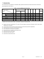
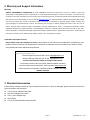
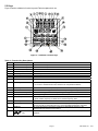
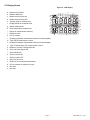
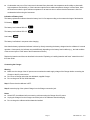
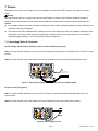
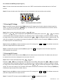
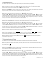
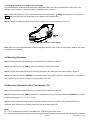
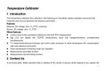
User Guide Multifunction Process Calibrator Model PRC70 1 Introduction This multifunction process calibrator is a handheld, battery-operated instrument that measures and sources electrical and physical parameters. (See Table 1) Table 1 - Source and Measurement Functions Measurement Function Sourcing Function DCI DCV RAMP ON RAMP OFF OHM FREQ PULSE SWITCH TC RTD DCV ● × ● ● ● ● ● ● ● DCI LOOP OFF LOOP ON ● × ● ● ● ● ● ● ● ● × ● ● ● ● ● ● ● OHM FREQ TC RTD SWITCH CONT. ● × ● ● ● ● ● ● ● ● × ● ● × × × ● ● ● × ● ● ● ● ● × × ● × ● ● ● ● ● × × ● × ● ● ● ● ● ● ● ● × ● ● ● ● ● ● ● In addition to the functions listed in Table 1, the calibrator includes the following features: z Measure and source simultaneously. The upper LCD area displays measurement information and the lower section displays source information. z Thermocouple measurement/source terminals and built-in lead connector (with RJ compensation) z Manual step source, auto-step, and sweeping-step source z Room temperature monitoring for all operations z Measurement/source temperature monitoring function z Measurement/source mA% display z Measurement wave-filter function z Measurement manual-hold function Page 2 PRC70-EN-V2.1 12/11 2 Warranty and Support Information Warranty EXTECH INSTRUMENTS CORPORATION (A FLIR COMPANY) warrants this instrument to be free of defects in parts and workmanship for one year from date of shipment (a six month limited warranty applies to sensors and cables). If it should become necessary to return the instrument for service during or beyond the warranty period, contact the Customer Service Department at (781) 890-7440 ext. 210 for authorization or visit our website www.extech.com for contact information. A Return Authorization (RA) number must be issued before any product is returned to Extech. The sender is responsible for shipping charges, freight, insurance and proper packaging to prevent damage in transit. This warranty does not apply to defects resulting from action of the user such as misuse, improper wiring, operation outside of specification, improper maintenance or repair, or unauthorized modification. Extech specifically disclaims any implied warranties or merchantability or fitness for a specific purpose and will not be liable for any direct, indirect, incidental or consequential damages. Extech's total liability is limited to repair or replacement of the product. The warranty set forth above is inclusive and no other warranty, whether written or oral, is expressed or implied. Calibration and Repair Services Extech offers repar and calibration services for the products we sell. Extech also provides NIST certification for most products. Call the Customer Care Department for information on calibration services available for this product. Extech recommends that annual calibrations be performed. Support line (781) 8907440 Technical Support: Extension 200; E-mail: [email protected] Repair & Returns: Extension 210; E-mail: [email protected] Product specifications subject to change without notice For the latest version of this User Guide, Software updates, and other up-to-the-minute product information, visit our website: www.extech.com Extech Instruments Corporation, 285 Bear Hill Road, Waltham, MA 02451 ISO9001 Certified 3 Standard Accessories Ensure that the package contains all of the accessories listed below. If items are damaged, please contact the vendor from which the product was purchased. z Two (2) sets of Industrial Test Leads z One set of standard Test Leads z One (1) set of Alligator clips z User's Guide z Two (2) Fuses 50mA/250V and 63mA/250V Page 3 PRC70-EN-V2.1 12/11 4 Safety Information For the correct and safe use of the instrument, be sure to follow the cautionary notes stated in this manual whenever handling the instrument. Extech Instruments shall not be held liable for any damage resulting from use of the instrument in a manner other than prescribed in the cautionary notes. A Warning identifies conditions and actions that pose hazards to the user; a Caution identifies conditions and actions that may damage the meter or the equipment under test. Refer to Table 2 for the international electric symbols adopted by the calibrator. Table 2 - International Electrical Symbols WARNING INFORMATION EARTH GROUND Warning To avoid possible electric shock or personal injury: z Do not apply more than the rated voltage, as marked on the calibrator, between terminals or between any terminal and earth ground; z Before use, verify the meter’s operation by measuring a known voltage; z Follow all equipment safety procedures; z Do not connect the probe of the test leads with any live power when the other end has been inserted into the current jack; z Do not use the meter if it is damaged. Before using the meter, inspect the case. Look for cracks or missing plastic. Pay particular attention to the insulation surrounding the connectors; z Select the proper function and range for the measurement; z Make sure the battery door is closed and latched before operating the meter; z Remove test leads from the meter before opening the battery door; z Inspect the test leads for damaged insulation or exposed metal. Check test lead continuity. Replace damaged test leads before using the meter; z When using the probes, keep fingers behind the finger guards on the probes; z Connect the common test lead before connecting the live test lead. When disconnecting test leads, disconnect the live test lead first; z Do not use the meter if it operates abnormally. Protection may be impaired. When in doubt, have the meter inspected; z Do not operate this instrument in areas where inflammable or explosive gases or vapor exists. It is extremely hazardous to use the instrument under such environments; z Do not operate the meter near explosive gas, vapor, or dust; z Use only four (4) AAA 1.5V batteries, properly installed in the meter case, to power the meter; z Disconnect the test leads before shifting to different source or measurement functions; z When servicing the meter, use only specified replacement parts. z To avoid false readings, which could lead to possible electric shock or personal injury, replace the batteries as soon as the low battery indicator ( ) appears. Caution To avoid possible damage to meter or to equipment under test: z Disconnect the power and discharge all high-voltage capacitors before testing resistance or continuity. z Use the proper jacks, functions, and ranges for the measurement or source operation. Page 4 PRC70-EN-V2.1 12/11 5 Calibrator Description Refer to Figure 1 1 1. LCD display 2. Digit up/down adjust buttons 2 3. Control keypad 4. Measurement terminals 3 5. Source terminals 4 5 Figure 1 – Meter Description 5.1 Measurement/ Source Terminals Figure 2 shows the calibrator’s measurement /source terminals. Table 3 explains their use. Figure 2 - Measurement/ Source Terminals Table 3 - Measurement/ Source Terminals Terminal 1 2 Function Common (COM) return(-)terminal for all measurement functions Measurement Signals(+):DCV, OHM, FREQ, TC, RTD, SWITCH, and CONT (continuity) 3 Measurement Signal(+):mADC 4 3W Terminal:measurement terminal of the 3W OHM, RTD LOOP Terminal:+24VDC Loop Power Terminal 5 Source Signal:(+)DCmA 6 Source Signals:(-)OHM、RTD 7 8 Common (COM) return(-)terminal for source functions Source Signal(+)DCV, OHM, TC, RTD, XMT, FREQ, CYC, and SWITCH Source Signal:(-)mADC Page 5 PRC70-EN-V2.1 12/11 5.2 Keys Figure 3 lists the calibrator’s function keys and Table 4 explains their use. Figure 3 – Calibrator Function Keys Table 4 – Function Key Descriptions No. Name Function 1~5 6~10 11 12 13 14 15 16 Source value set key Source value set key Measurement ON key Source ON key Power key Backlight Measurement FUNC Key Source FUNC Key Increment source set point Decrement source set point Switch measurement functions ON or OFF Switch source function ON or OFF Switch the power ON or OFF Switch the backlight ON or OFF Select measurement function Select source function 17 TEMP Key Switch room temperature monitoring function ON or OFF In TC source or measurement mode, switch the RJ compensation ON/OFF 18 19 20 21 22 ZERO Key Measurement RANGE Key Source RANGE Key AVG Key 25/100% key Set the source value to zero-point; In pulse source function, set the pulse number. Select measurement range; Measurement mA and percentage shifting. Select source range; Source mA and percentage shifting. Measuring average value 23 24 HOLD Key START Key 25 LOOP Key 26 Key In mA source function, select 25% or 100% manual step output mode. In pulse number, frequency or switch source, set the frequency value. Freeze measured value Source auto-pulse number, switch ON mA auto-stepping or sweeping function. Convert sourced TC temperature and mV, and sourced RTD temperature and Ohms. 24v Loop circuit power: Convert the measured TC temperature and the mV, the measured RTD temperature and the Ohms. In DCmA source mode, select auto-wave; In frequency/pulse source mode, set amplitude Page 6 PRC70-EN-V2.1 12/11 5.3 Display Screen Figure 4 - LCD display a. Battery level indicator b. Measure Mode icon c. Measurement function ON d. Measurement function OFF e. Average value for measurement f. Display HOLD for measured value g. Switch measurement h. Room temperature measurement c d e g f a b I j x l m n r s t u i. Beeper for measurement continuity j. Measured value k. Unit of measure l. Dividing line between measurement and source mode displays h k o q p w y v m. Type of RTD measurement / source n. Dividing line between measurement and source mode displays o. Type of Thermocouple (TC) measurement / source p. Reference Junction Compensation ON q. 24V Loop Power Supply ON r. Source Mode icon s. Source function ON t. Source function OFF u. Set -point for source v. RUN icon for auto-step and auto-sweep w. Unit of measure for setpoint of source x. Not used y. Not used Page 7 PRC70-EN-V2.1 12/11 6 Source/Measurement Preparations Precautions for Safe Use of the Instrument z When using the instrument for the first time, be sure to read the instructions given in Section 4 “Precautions for Safe Use of the Instrument.” z Do not open the instrument’s case. Contact the vendor for service. z In case of failure: Should the instrument begin to emit smoke, give off an unusual odor, or show any other anomaly, immediately switch OFF the POWER. If using an AC Charger, disconnect the plug from the wall outlet. Also switch OFF power to the object under test that is connected to the input terminals. Contact the vendor. z Charger: Use an AC Charger dedicated to the instrument. Avoid placing any load on the Charger; prevent any heatemitting object from coming into contact with the adapter. General Handling Precautions z Before transporting the instrument, switch OFF power to the object under test, and then power off the meter. When using an AC Charger, disconnect the power cord from the wall outlet. Finally, detach all lead cables from the instrument. Use a dedicated carry case when transporting the instrument. z Do not bring any electrified object close to the input terminals, since this may damage the internal circuitry. z Do not apply any volatile chemical to the instrument’s case or operation panel. Do not leave the instrument in contact with any product made of rubber or vinyl for a prolonged period. Be careful not to let a soldering iron or any other heatemitting object come into contact with the operation panel (panel is made of thermoplastic resin). z Before cleaning the instrument’s case or operation panel, disconnect the power cord plug from the wall outlet if using an AC Charger. Use a soft, damp cloth to gently wipe the outer surfaces of the instrument. Water that is allowed into the instrument can result in malfunction. z If using an AC Charger, disconnect the power cord plug from the wall outlet when the meter is not in use. z For handling precautions regarding the batteries, see “Installing or Replacing the Batteries”. z Never use the instrument with the cover of the battery holder opened. Environmental Requirements Use the instrument in locations that meet the following environmental requirements: z Ambient temperature and humidity: Ambient temperature range: 32 to 122oF (0 to 50oC); ambient humidity range: 30 to 80% RH; non-condensing. z Place the instrument on flat and level areas Do not use the instrument in locations that are: z Exposed to direct sunlight or close to any heat source. z Exposed to frequent mechanical vibration. z Close to an electrical noise source, such as high-voltage equipment or motive power sources. z Close to any source of intensive electric or electromagnetic fields. z Exposed to large amounts of grease fumes, hot steam, dust or corrosive gases. z Exposed to unstable areas such as where a risk of explosion due to the presence of flammable gases exists. Notes: z Use the instrument under the following environmental conditions when precise measurements are required: Ambient temperature range: 74oF (23oC) ±5o; ambient humidity range: 20 to 80% RH (non-condensing) z When using the instrument within a temperature range of 32 to 64oF (0 to 18oC) or 82 to 122oF (28 to 50oC), add a value based on the temperature coefficient shown in the “Specifications” section to the given accuracy rating. z When using the instrument at an ambient humidity of 30% or lower, prevent electrostatic charges from being produced by using an antistatic mat or other alternative means. Page 8 PRC70-EN-V2.1 12/11 z Condensation may occur if the instrument is relocated from places with low temperature and humidity to places with high temperature and humidity, or if the instrument experiences a sudden temperature change. In these cases, leave the instrument under the given ambient temperature for at least one hour to ensure that the instrument is free from condensation before using the instrument. Indication of Battery Level The battery replacement indicator shows the battery level in five steps according to the measured voltage of the batteries. Full battery: The battery level is below 50% full: The battery level is below 25% full: Low battery: The battery icon flashes in sequence when charging. Note that the battery replacement indicator is driven by directly measuring the battery voltage when the calibrator is in actual operation. Consequently, the indicator may read differently depending on the battery load condition (e.g., the load condition of the source output or on/off state of the measurement function). Replace the batteries and fuses as described in the section “Replacing or installing batteries and fuses” toward the end of this User Guide. Connecting the Charger Warning z Make sure the voltage of the AC power source matches the rated supply voltage of the Charger before connecting the Charger to the AC power source. z Do not use a Charger other than the dedicated, supplied Charger. z Do not charge non Ni-Cd, Ni-MH batteries. Step 1: Ensure that the calibrator is OFF. Step 2: Insert the plug of the optional Charger into the Charger connection jack. Notes: z Switch OFF the calibrator before connecting or disconnecting the Charger from AC power. z Unplug the Charger from the Charger connection jack of the calibrator when discharging. z Do not charge the calibrator without batteries installed. Page 9 PRC70-EN-V2.1 12/11 Switching Power ON Press the power key once to switch ON the calibrator. Press and hold the power key for 2 seconds to switch OFF the calibrator. Switching MEASURE Mode ON and OFF The measurement function defaults to the OFF state each time the calibrator is switched ON. z Use the MEASURE (ON) key to switch the MEASURE mode ON/OFF. z If the MEASURE function is not needed and therefore switched OFF, power to the measurement circuit is also switched OFF within the calibrator. Thus, battery power is saved. z Turning off the MEASURE function causes the on-screen measured value to switch off and the “OFF” indicator to appear. z To resume measurement when the MEASURE function is off, press the MEASURE (ON) key again. Automatic Power OFF When the calibrator is running on battery power, and no key is pressed for approximately ten minutes, the calibrator switches OFF automatically. The automatic power-off time can be programmed or set to the factory default state, see the “Programming the Global Settings” section. Switching the LCD Backlight ON and OFF Press the backlight key to switch ON the backlight; press again to switch it OFF. Battery life is shortened by backlight overuse. Notes: The backlight automatically switches OFF after 30 seconds. The time can be programmed or reset to the factory default condition, see the “Programming the Global Settings” section. Page 10 PRC70-EN-V2.1 12/11 7 Source The calibrator can source a DC voltage, DC current, resistance, thermocouple, RTD, frequency, pulse signal or contact output. Warning To avoid electrical shock, do not apply more than the rated voltage, as marked on the calibrator, between terminals or between any terminal and earth ground. Always use the calibrator in locations with a voltage to ground value below 30V. Caution z Do not apply voltage to the output terminals for ranges other than 4-20mA simulating transmitter outputs. Otherwise, the internal circuitry may be damaged. z The instrument has been calibrated without taking into account the voltage drop due to the resistance component of the lead cables. Care must be taken therefore when drawing a load current since the voltage drop due to the resistance component (approximately 0.1 Ω) of the lead cables induces a slight error. 7.1 Connecting Cables to Terminals For DC voltage, thermocouple, frequency, pulse or contact output (see Figure 5) Step 1: Connect the black lead cable for source to the COM output terminal and the red lead cable to the “VhzTcmA-” output terminal. Step 2: Connect the other ends of the cables to the input of equipment under test ensuring the polarities are correct. Figure 5 - Sourcing DC voltage, TC, frequency, pulse and contact output For DC current (see Figure 6) Step 1: Connect the black lead cable for source to the “VhzTcmA-” output terminal and the red lead cable to the ‘’mA+’’ output terminal. Step 2: Connect the other ends of the cables to the input of equipment under test ensuring correct polarity. Figure 6 - Sourcing DC Current Page 11 PRC70-EN-V2.1 12/11 For resistance and RTD signal (see Figure 7) Step 1: Connect the two black lead cables for source to the ‘’ΩRTD’’ terminal and the red lead cable to the “VhzTcmA-” terminal. Step 2: Connect the other ends of the cables to the input of equipment under test ensuring correct polarity. Figure 7 - Sourcing Resistances and RTD 7.2 Sourcing DC Voltage Step 1: Using the Function selector switch (FUNC) select the DC voltage source function, select the desired range from 100mV, 1V, and 10V by pressing the〔RANGE〕key. The default value, the unit of the selected source function, and the range is displayed in the lower area of the LCD. Step 2: Set the output value digit by digit using the 〔S〕/〔T〕keys. Each pair of 〔S〕/〔T〕keys corresponds to each digit of the LCD reading. Each press of the 〔S〕/〔T〕key increases or decreases the digit. Increasing the digit from 9 or decreasing it from 0 causes the digit to overflow or underflow, allowing the output value to be set without interruption. Holding down the 〔S〕/〔T〕key changes the digit in question quickly. The value will not change if it is increased or decreased to the Maximum or Minimum value. Pressing the (ZERO) key initializes the output set point to the default value (0). Step 3: Pressing the (ON) key causes the indicator on the LCD to change from ‘’OFF‘’ to ‘’ON ‘’. The calibrator sources the preset DC voltage between the output terminals. Step 4: To switch OFF the output, press the (ON) key again. The’’ OFF ‘’ icon appears on the LCD and no signals are sourced between the terminals. 7.3 Sourcing DC Current Step 1: Using the Function selector switch (FUNC) select the desired source function 20mA. The default value and unit of the selected source function is displayed in the lower area of the LCD. Step 2: Set the output value digit by digit using〔S〕/〔T〕keys. Each pair of〔S〕/〔T〕keys corresponds to each digit of the LCD reading. Each press of the〔S〕/〔T〕key increases or decreases the digit. Increasing the digit from 9 or decreasing it from 0 causes the digit to overflow or underflow, allowing the output value to be set without interruption. Holding down the〔S〕/〔T〕key continuously changes the digit in question quickly. The value won’t change if it is increased or decreased to the Maximum or Minimum value. Pressing the (ZERO) key initializes the output set point to the default value (0). Step 3: Pressing the (ON) key causes the indicator on the LCD to change from ‘’OFF‘’ to ‘’ON ‘’. The calibrator sources the preset DC voltage between the output terminals. Step 4: To switch OFF the output, press the (ON) key again. The OFF icon appears on the LCD. Page 12 PRC70-EN-V2.1 12/11 7.3.1 Manually Set 25%, 100% 4–20 mA Function The source can be set within the 4–20 mA current range. Step 1: In DC current mode, press the〔25%100%〕key to display “25%SET” on the lower part of the screen, and press again to display “100%SET”. The default source values will be shown. Step 2: Using each pair of 〔S〕/〔T〕output setting keys, set the signal in a step-by-step manner. In the 25% set point condition, the signal can be set in 4 mA increments or decrements in the sequential order 4-8-12-16-20 by each press of the key. In the 100% set point condition, the signal can set in 16 mA increments or decrements by each press of the key. Pressing the (ZERO) key initializes the signal set point to the default value (4.00). Step 3: Pressing the (ON) key causes the indicator on the LCD to change from ‘’OFF‘’ to ‘’ON ‘’. The calibrator sources the preset 4–20 mA current signal between the output terminals. Step 4: To switch OFF the output, press the (ON) key again. The’’ OFF ‘’appears on the LCD and no signals are sourced between the terminals. 6.3.2 Auto-stepping and auto-sweeping 4-20mA function The user can set a 4–20 mA range in which to auto-step or auto-sweep. 80 seconds are required to finish a 4-20mA cycle in auto-sweeping mode and 20 seconds are required for auto-stepping mode. Step 1: In the DC current mode, press the 〔 〕key to display the auto-stepping mode icon “ the screen; press again to display the auto-sweeping mode icon “ ” on the lower part of ”. The default source value will display. Step 2: Pressing the (ON) key causes the indicator on the LCD to change from ‘’OFF‘’ to ‘’ON ‘’. The calibrator sources the default 4–20 mA current signal between the output terminals. Step 3: Pressing the (START) key starts the auto-stepping or the auto-sweeping mode. The “RUN” icon is displayed in the lower part of the LCD. Step 4: Pressing the (START) key again stops the auto-stepping or the auto-sweeping mode. The “RUN” icon switches OFF. Step 5: Pressing the (ON) key cancels the sourcing and the ‘’OFF’’ icon is displayed on the screen. No signals are sourced between the terminals. Notes: z Press the (START) key again to continue the auto-stepping or the auto-sweeping mode after stopping them; The “RUN” icon is displayed on the lower part of the screen. z The ability to use the (START) key to start mA auto-stepping and auto-sweeping mode is only available when the source function is in the ON state. z Starting the mA auto-sweeping mode switches OFF the measurement mode. The mA auto-stepping mode and the measurement function cannot run simultaneously. Page 13 PRC70-EN-V2.1 12/11 7.3.3 mA% display In the mA source mode, press the (RANGE) key to convert the preset source value to mA% mode (shown on the lower part of the LCD) as described in the following equation. 100 (current measured value mA-4mA) mA % = % 16 mA Press the (RANGE) key to return to the current preset value (shown on the lower part of the LCD). Notes: Increment/decrement setting functionality is not available in mA% mode. Press the (RANGE) key again to return to the source set mode. 7.3.4 4-20 mA simulate transmitter source Connect the calibrator and loop power as shown in Figure 8. Operate as described in the DC current Source section. Figure 8 - 4-20 mA simulation transmitter source 7.4 Sourcing Resistance z The calibrator sources a resistance signal by receiving the resistance-measuring current (I) supplied from the device being calibrated (such as a resistance meter) and then delivering the voltage (V) proportional to the preset resistance (R) between the output terminals, and thus producing the equivalent resistance R =V/I. Consequently, the calibrator sources the signal correctly only for devices that use this method of measurement. z The allowable range of the resistance measuring current that the calibrator receives from a resistance measuring device under calibration is rated as 0.1 to 3 mA. To ensure accuracy, the resistance measuring current from the device under calibration is strictly confined within the range. See the “Specifications” section. z Any resistance signal being sourced does not include the resistance component of the lead cables. The whole resistance, when measured at the ends of the lead cables for sourcing, is found by adding the resistance of the lead cables (approximately 0.1 ohm) to the sourced resistance signal. For the sourcing of precise resistance signals, use a three-wire or a four-wire connection. z If capacitance between the terminals of a device under calibration is greater than 0.1µF, the calibrator may fail to source correct resistance signals. Step 1: Using the function selector switch (FUNC), select the Ohm mode. Using the (RANGE) key, select the range. The selected function, the default range source value, and the unit are shown in the lower part of the LCD. Step 2: Set the output value, digit by digit, using each pair of〔S〕/〔T〕keys. Each pair of〔S〕/〔T〕keys corresponds to each digit of the LCD reading. Each press of the〔S〕/〔T〕key increases or decreases the digit. Increasing the digit from 9 or decreasing it from 0 causes the digit to overflow or underflow, allowing the output value to be set without interruption. Holding down the〔S〕/〔T〕key changes the digit in question quickly. The Page 14 PRC70-EN-V2.1 12/11 value won’t change if it is increased or decreased to the Maximum or Minimum value. Pressing the (ZERO) key initializes the output set point to the default value (0). Figure 9 - Connection method based on three-wire and four-wire Step 3: Pressing the (ON) key causes the SOURCE indicator on the LCD to change from ‘’OFF‘’ to ‘’ON ‘’. The calibrator sources the preset resistance value between the output terminals. Step 4: To switch OFF the output, press the (ON) key again. The ‘’OFF‘’ icon appears on the LCD and no signals are sourced between the terminals. The connection method based on three-wire and four-wire is shown in Figure 9: 7.5 Simulate Sourcing TC (Thermocouple Temperature) Note that the calibrator is designed to include an internal temperature sensor. To calibrate a device without using external 0oC reference junction temperature compensation, use the RJ sensor function. The “RJ-ON” icon appears on the middle part of the screen when activated. If the RJ function is not used, an external 0oC reference will be required. Step 1: Using the function selector key (FUNC), select the TC source function. Using the (RANGE) key select the desired thermocouple type (K, E, J, T, B, N, R, S). The selected function, the default range source value, and the unit of measure are shown in the lower part of the LCD. Step 2: Set the output value digit by digit using each pair of〔S〕/〔T〕keys. Each press of the〔S〕/〔T〕key increases or decreases the digit. Increasing the digit from 9 or decreasing it from 0 causes the digit to overflow or underflow, allowing the output value to be set without interruption. Holding down the〔S〕/〔 T〕key changes the digit in question quickly. The value won’t change if it is increased or decreased to the Maximum or Minimum value. Pressing the (ZERO) key initializes the output set point to the default value. Step 3: Pressing the (ON) key causes the SOURCE indicator on the LCD to change from OFF to ON. A thermoelectromotive force based on the temperature detected by the RJ sensor develops between the output terminals. Step 4: To switch OFF the output, press the (ON) key again. The ‘’OFF‘’ icon appears on the LCD and no signals sourced between the terminals. Note: If the reference junction compensation is not needed, press the〔RJ-ON〕key to switch it OFF. With the RJ compensation switched OFF, the calibrator will only source an accurate value when external 0oC reference junction compensation is used. Page 15 PRC70-EN-V2.1 12/11 7.5.1 Temperature (TC) Monitor Function The calibrator offers a temperature monitor function convenient for observing the voltage value sourced between the output terminals in TC source mode. In the TC source mode, press the (START) key and the LCD will show the voltage value sourced between the output terminals (this value varies in response to the changes of the reference junction compensation). Press the (START) key again and the LCD will show the preset temperature value. 7.6 Sourcing RTD Temperature z First, the calibrator sources a resistance signal by receiving the resistance-measuring current (I) supplied from the device being calibrated (such as a resistance meter) and then delivering the voltage (V) proportional to the preset resistance (R) between the output terminals, and thus producing the equivalent resistance R =V/I. Consequently, the calibrator sources the signal correctly only for such devices that employ this method of measurement. z The allowable range of the resistance measuring current that the calibrator receives from a resistance measuring device under calibration is rated as 0.1 to 3 mA. To ensure accuracy, the resistance measuring current from the device under calibration is strictly confined within this range. For further details, see the “Specifications” section. z Sourced resistance signals do not include the resistance component of the lead cables. The entire resistance, when measured at the ends of the lead cables for sourcing, is given by adding the resistance of the lead cables (approximately 0.1 ohms) to the sourced resistance signal. For the sourcing of precise resistance signals, use three-wire or four-wire connections. Step 1: Using the function key (FUNC), select the RTD function. Using the (RANGE) key, select a RTD range (PT100, PT200, PT500, PT1000, Cu10, Cu50). The selected function, the default range source value, and the unit of measure are shown in the lower area of the LCD. Step 2: Set the output value digit by digit using each pair of〔S〕/〔T〕keys. Each press of the〔S〕/〔T〕key increases or decreases the digit. Increasing the digit from 9 or decreasing it from 0 causes the digit to overflow or underflow, allowing the output value to be set without interruption. Holding down the〔S〕/〔 T〕key changes the digit in question quickly. And the value won’t change if it is increased or decreased to the Maximum or Minimum value. Pressing the (ZERO) key initializes the output set point to the default value (0). Step 3: Pressing the (ON) key causes the SOURCE indicator on the LCD to change from ‘’OFF‘’ to ‘’ON ‘’. The calibrator sources the preset resistance value between the output terminals. Step 4: To switch OFF the output, press (ON) again. The ‘’OFF‘’ icon appears on the LCD and no signals are sourced between the terminals. The connection methods based on three-wire and four-wire are shown in Figure 9. Note: The RTD source function is unavailable if the TC /RTD measurement function is ON. 7.6.1 Temperature Monitor Function The calibrator offers a temperature monitor function for easily observing the resistance value sourced between the output terminals. In the RTD source mode, press the (START) key and the LCD will show the resistance value sourced between the output terminals. Press (START) again and the LCD will show the preset temperature value. Page 16 PRC70-EN-V2.1 12/11 7.7 Sourcing Frequency The calibrator can source a constant pulse signal according to the preset frequency and amplitude. Step 1: Using the function selector switch (FUNC), select the frequency source function. The LCD shows the default frequency value (10 Hz) and the frequency symbol in the lower LCD area. Step 2: Using the (RANGE) key, select a frequency range (100Hz, 1KHz, 10Hz, 100KHz). The selected function, the default range source value, and the unit of measure are shown in the lower area of the LCD. Step 3: Set the output value digit by digit using each pair of〔S〕/〔T〕output setting keys. Each pair of〔S〕/〔T〕keys corresponds to each digit of the LCD reading. Each press of the〔S〕/〔T〕key increases or decreases the digit. Increasing the digit from 9 or decreasing it from 0 causes the digit to overflow or underflow, allowing the output value to be set without interruption. Holding down the〔S〕/〔T〕key changes the digit quickly. The value won’t change if it is increased or decreased to the Maximum or Minimum value. Step 4: Pressing the〔VPEAK〕key once switches to the amplitude setting mode. The LCD shows a reading of 1V. Step 5: Set the output value digit by digit using each pair of〔S〕/〔T〕output setting keys. Each pair of〔S〕/〔T〕keys corresponds to each digit of the LCD reading. Each press of the〔S〕/〔T〕key increases or decreases the digit. Increasing the digit from 9 or decreasing it from 0 causes the digit to overflow or underflow, allowing the output value to be set without interruption. Holding down the〔S〕/〔T〕key changes the digit quickly. The value won’t change if it is increased or decreased to the Maximum or Minimum value. Step 6: To re-enter the frequency set mode and set the frequency, press the〔FREQ〕key. Step 7: Pressing the (ON) key causes the SOURCE indicator on the LCD to change from ‘’OFF‘’ to ‘’ON ‘’. The calibrator sources constant pulse signals between its output terminals according to preset frequency and amplitude. Step 8: To switch OFF the output, press the (ON) key again. The ‘’OFF‘’ icon appears on the LCD and no signals are sourced between the terminals. 7.8 Sourcing a Number of Pulses The calibrator can source a preset number of pulse signal according to the preset frequency and amplitude. Step 1: Using the function selector switch (FUNC), select the pulse source function. The LCD shows the default value (10 Hz) and the pulse icon . Step 2: Using the (RANGE) key, select a frequency range. The selected function, the default range source value, and the unit of measure are shown in the lower portion of the LCD. Step 3: Set the output value digit by digit using each pair of〔S〕/〔T〕output setting keys. Each pair of〔S〕/〔T〕keys corresponds to each digit of the LCD reading. Each press of the〔S〕/〔T〕key increases or decreases the digit. Increasing the digit from 9 or decreasing it from 0 causes the digit to overflow or underflow, allowing the output value to be set without interruption. Holding down the〔S〕/〔T〕key changes the digit quickly. The value won’t change if it is increased or decreased to the Maximum or Minimum value. Page 17 PRC70-EN-V2.1 12/11 Step 4: Pressing the〔VPEAK〕key once switches to the amplitude setting mode. The LCD shows a reading of 1V. Step 5: Set the output value digit by digit using each pair of 〔S〕/〔T〕output setting keys. Each pair of〔S〕/〔T〕keys corresponds to each digit of the LCD reading. Each press of the〔S〕/〔T〕key increases or decreases the digit. Increasing the digit from 9 or decreasing it from 0 causes the digit to overflow or underflow, allowing the output value to be set without interruption. Holding down the〔S〕/〔T〕key changes the digit quickly. The value won’t change if it is increased or decreased to the Maximum or Minimum value. Step 6: Press the (CYC) key to enter the pulse number set mode; the LCD will show the default value (1 CYC). Step 7: Set the output value digit by digit using each pair of〔S〕/〔T〕output setting keys. Each pair of〔S〕/〔T〕keys corresponds to each digit of the LCD reading. Each press of the〔S〕/〔T〕key increases or decreases the digit. Increasing the digit from 9 or decreasing it from 0 causes the digit to overflow or underflow, allowing the output value to be set without interruption. Holding down the〔S〕/〔T〕key changes the digit quickly. The value won’t change if it is increased or decreased to the Maximum or Minimum value. Step 8: To re-enter the frequency set mode, press the〔FREQ〕key. Step 9: Pressing the (ON) key causes the SOURCE indicator on the LCD to change from ‘’OFF‘’ to ‘’ON ‘’, and the calibrator sources low level signals between its output terminals. Step 10: Press the (START) key to allow the calibrator to source the set number of pulses according to the preset frequency and amplitude, the LCD will show the “RUN” icon. Step 11: When source is complete, the calibrator automatically switches the output OFF and ceases operation. The “RUN” symbol also switches OFF. Step 12: To switch OFF the output manually, press the (ON) key again. The ‘’OFF‘’ icon appears on the LCD and no signals will be sourced between the terminals. Notes: z The frequency range of the pulse can only be changed by pressing (RANGE) in the frequency set mode. z When the “RUN” symbol switches OFF, the user can change the frequency and amplitude when the source function is in ‘’ON ‘’ or ‘’OFF‘’. z During the pulse sourcing process, pressing the (START) key causes the calibrator to switch the output OFF; the “RUN” icon switches OFF also. Press the (START) key again to restart the sourcing function. z Restarting the pulse output requires that the source function be in the ‘’ON ‘’state. Page 18 PRC70-EN-V2.1 12/11 7.9 Sourcing Contact Output Switch the output terminals ON or OFF using the contact output function. The contact-switching device is an FET. Step 1: Using the function key (FUNC), select the contact output source function. The LCD shows the default value (10Hz) and the “ “ switch symbol. Step 2: Using the (RANGE) key, select a frequency (100Hz, 1KHz, 10 KHz, 100KHz). Step 3: Set the output value digit by digit using each pair of〔S〕/〔T〕output setting keys. Each pair of〔S〕/〔T〕keys corresponds to each digit of the LCD reading. Each press of the〔S〕/〔T〕key increases or decreases the digit. Increasing the digit from 9 or decreasing it from 0 causes the digit to overflow or underflow, allowing the output value to be set without interruption. Holding down the〔S〕/〔T〕key changes the digit quickly. The value won’t change if it is increased or decreased to the Maximum or Minimum value. Step 4: Pressing the (ON) key causes the SOURCE indicator on the LCD to change from ‘’OFF‘’ to ‘’ON ‘’. Step 5: To switch the output OFF, press the (ON) key again. The ‘’OFF‘’ icon appears on the LCD and signals sourced between its terminals will be switched OFF. Notes: z The contact output source function is unavailable if the frequency measurement function is ON. z The amplitude and pulse number cannot be set when in the contact output mode. z The contact output is polarized. Generally, connect the positive polarity with the high (H) jack of the calibrator and the negative polarity with the low (L) jack. z Note that the maximum allowable current for the contact output is 50mA. 7.10 Zero-off function For any DC voltage, DC current, Resistance (ohms), TC (thermocouple) or RTD range, pressing the (ZERO) key initializes the preset source value. In the frequency, pulse, and contact output modes, the (ZERO) key is unavailable. Page 19 PRC70-EN-V2.1 12/11 8 Measurement The calibrator measures DC voltage, DC current, resistance, thermocouple, RTD, frequency, continuity, switch and pressure. Warning z In applications where the calibrator is used together with the supplied test lead cables for measurement, the allowable voltage to ground of the input terminals is 60V maximum. To avoid electrical shock, do NOT use the calibrator at voltages exceeding the maximum voltage to ground. z The allowable voltage to ground when the supplied thermocouple convertor is attached to the input terminals is 60V peak maximum. To avoid electrical shock, do not use the terminal adapter for measuring circuit voltage exceeding the maximum voltage to ground. Notes: z When switching the calibrator ON, the measurement function is in the OFF mode to save battery power. Press the (ON) key to enable the desired function. z When in the mA source mode and using the auto-sweeping mode, the measurement function cannot be started by pressing the (ON) key (the LCD will indicate the “NO. OP” error). z Using the〔HOLD〕key, the measured value can be frozen on the display. z Switch OFF the MEASURE mode by pressing the (ON) key when the meter is be unused for a period of time. The measured value shown on the LCD switches OFF and power to the internal measuring circuit is switched OFF. This saves on battery power. z The LCD shows all dashes “- - - - -“on the upper area when the range is changed by the user. If the input is over loaded (over range), the measured value on the LCD indicates “oL”. 8.1 Connecting Cables to Terminals For DC voltage, Ohm, frequency, continuity, or switch mode (Figure 11) Step 1: Connect the black test lead cable for measurement to the “COM” input terminal and the red test lead cable to the ”VHzTc ΩRTD” input terminal. Figure 11 - Measuring DC voltage, ohms, frequency, continuity and switch Step 2: Connect the other end of the cables to the terminal points of the equipment under test while ensuring that the polarities are correct. Page 20 PRC70-EN-V2.1 12/11 For DC current signals (refer to Figure 12) Step 1: Connect the black test lead cable for measurement to the “COM” input terminal and the red test lead cable to the “mA” input terminal. Step 2: Connect the other end of the cable to the measuring terminals of the equipment under test ensuring that the polarities are correct. Figure 12 - Measuring DC current For thermocouple signals (refer to Figure 13) Step 1: Connect the thermocouple convertor to the input terminals. Step 2: Connect between the TC terminals. The positive output lead wire of the thermocouple to the H terminal of the thermocouple convertor and the negative output lead wire of the thermocouple to the L terminal. Figure 13 - Measuring TC (thermocouple temperature) Three wire connection method for RTD signals (Figure 14) Step 1: Connect one black lead cable for measurement to the “COM” input terminal and another black lead to the “3W” terminal. Connect the red lead cable to the “VHzTcΩRTD” input terminal. Step 2: Connect the three clips of the cables to the measuring terminals of the equipment under test ensuring that the polarities are correct. Figure 14 - RTD signal with 3w method Page 21 PRC70-EN-V2.1 12/11 z z Warning Before connecting the calibrator to the device under test, switch OFF the power to the device. Do not apply voltage or current exceeding the allowable voltage (60 V) or current (55 mA). Exceeding the limits will endanger instrument and also create a risk of personal injury due to electrical shock. z Mistaking the H voltage input terminal for the mA current input terminal, and vice versa, when wiring, is extremely dangerous. Take great care in making connections and always double check the accuracy of the connection configuration. z The current input terminals are equipped with a built-in current input protection fuse. Over-current input to the terminals will cause the fuse to blow. If the fuse is blown, replace it following specified ratings. For details on fuse replacement, see the “Replacing the battery and fuse” section. Warning Wiring or operational errors can lead to damage to the instrument and personal injury due to electrical shock. Exercise the utmost care when carrying out the measurement tasks. 8.2 Measuring DC Voltage Step 1: Ensure that the test lead cables are not connected to the instrument or device under test. Step 2: Using the function key (FUNC), select the DC Voltage measurement function. Step 3: Connect the test lead cables to the terminals of the instrument under test. Step 4: Using the (RANGE) key, select a range from 50mV, 500mV, 5V, 50V. The selected function, the measured value, and the unit of measure are shown in the upper area of the LCD. 8.3 Measuring DC Current Step 1: Ensure that the test lead cables are not connected to the instrument or device under test. Step 2: Using the function key (FUNC), select the DC Current measurement function. Step 3: Connect the test lead cables to the measuring terminals of the instrument under test. Step 4: The selected function, the measured value, and the unit of measure are shown in the upper area of the LCD. 87.3.1 mA % Display In the mA measurement mode, pressing the (RANGE) key converts the measured value to the mA% mode (shown on the upper area of the LCD). See the equation below. 100 (current measured value mA-4mA) mA %= % 16 mA Press the (RANGE) key again to return to the measured value, shown on the upper area of the LCD. Page 22 PRC70-EN-V2.1 12/11 8.3.2 Using the Calibrator as a 24-V Loop Power Supply This function helps to switch ON a 24V loop power supply connected in line with the measured DC current circuit. The calibrator can be used as a loop power supply for calibrating 2-wire converters: Step 1: When the calibrator is in the current measurement mode, pressing the〔LOOP〕key causes the LCD to show the LOOP symbol and the built-in 24V loop power of the calibrator will be switched ON. Step 2: Connect the calibrator with the loop current terminals of the converter as shown in Figure 15. Figure 15 – A 24v loop power circuit supply Note: Since the function discussed above requires a significant amount of DC current (25 mA), battery operation will reduce the battery life considerably. 8.4 Measuring Resistance Step 1: Ensure that the test lead cables are not connected to the instrument under test. Step 2: Using the function key (FUNC), select the resistance measurement function. Step 3: Connect the test lead cables to the measuring terminals of the instrument under test as shown in Figure 11. Step 4: Using the measurement (RANGE) key, select the desired range 500Ω or 5KΩ.The selected function, the measured value, and the unit of measure are shown in the upper area of the LCD. 8.5 Measuring Temperature with a Thermocouple (TC) Step 1: Ensure that the test lead cables are not connected to the instrument under test. Step 2: Using the function key (FUNC), select the TC measurement function. Use the measurement (RANGE) key to select the thermocouple type: K, E, J, T, B, N, R, or S. Step 3: Connect the thermocouple convertor to the jack under test as shown in Figure 13.The selected function, the measured value, and the unit of measure are shown in the upper area of the LCD. Notes: z The TC measurement function is unavailable if the TC/RTD source function is ON. z If there has been a sudden change in the operating ambient temperature of the calibrator, wait until the built-in reference Page 23 PRC70-EN-V2.1 12/11 junction compensation stabilizes. 8.5.1 Using the RJ sensor Use the RJ-ON key to turn the Resistance Junction Temperature compensation ON or OFF. With the temperature compensation ON, the display will show the RJ-ON icon and the internal temperature (top right of the LCD). 8.5.2 Temperature Monitor Function The calibrator offers a temperature monitoring function to observe the voltage value measured from the input terminals. In the TC measurement mode, pressing the (T.DISPLAY) key shows the voltage value measured. Pressing the key again shows the measured temperature value. 8.6 Measuring Temperature with an RTD Step 1: Ensure that the test lead cables are not connected to the instrument under test. Step 2: Using the function key (FUNC), select the RTD measurement function. Step 3: Connect the test lead cables to the terminals of the instrument under test as shown in Figure 14. Step 4: Using the measurement (RANGE) key, select the desired range from PT100, PT200, PT500, PT1000, Cu10, and C50.The selected function, the default measured value, and the unit of measure are displayed. Notes: z The RTD measurement function is unavailable if the TC /RTD source function is ON. z The calibrator defaults to the 3-wire connection method when measuring RTD. When using the 2-wire connection method, pay special attention to linking (shorting) the “COM” and “LOOP” terminals. 7.6.1 Temperature Monitor Function The calibrator offers a temperature monitoring function to observe the resistance value measured from the input terminals. In the TC measurement mode, pressing the (T.DISPLAY) key shows the resistance value measured from the input terminals. Pressing the key again shows the measured temperature value. 8.7 Measuring Frequency Step 1: Ensure that the test lead cables are not connected to the instrument under test. Step 2: Using the function key (FUNC), select the frequency measurement function. Step 3: Connect the test lead cables to the measuring terminals of the instrument under test. Step 4: Using the measurement (RANGE) key, select the suitable range (500Hz, 5KHz, 50KHz).The selected function, the measured value, and the unit of measure are shown in the upper part of the LCD. Note: The frequency measurement function is unavailable if the frequency, pulse, contact or pressure source function is ON. Page 24 PRC70-EN-V2.1 12/11 8.8 Measuring switch The calibrator can measure the opening and closing of a dry contact switch. Using the function key (FUNC), select the switch measurement function. The LCD displays the switch symbol second if the state of the switch changes (opens or closes). ”on the upper area. The beeper sounds for one 8.9 Measuring Continuity Continuity measurements are used to detect the completeness of a circuit or wire (e.g. a resistance smaller than 50 ohms). Using the function selector switch (FUNC), select the continuity measurement function. The LCD displays the continuity symbol “ ”on the upper area. Connect the devices as shown in Figure 11, and the beeper will sound continuously if the loop circuit resistance is smaller than 50Ω; The LCD shows the measured resistance. 8.10 Measurement-filtering function Selecting the measurement-filtering function stabilizes the measured value displayed on the LCD. In the DCV, DCmA, OHM, TC, RTD modes pressing (AVG) key causes a calculation for the average of the samples. The LCD shows the “AVG” symbol. Pressing the (AVG) key again cancels the calculation and the “AVG” symbol switches OFF. 8.11 Measured Value HOLD function Apart from the continuity and switch measurement functions, the HOLD function can be used to freeze the measured value on the upper part of LCD. Pressing the (HOLD) key activates the HOLD mode, and the LCD displays the “HOLD” symbol. To exit HOLD mode, press the (HOLD) key again; the “HOLD” symbol switches OFF. 9 Environmental Temperature Test The calibrator can measure the surrounding environmental temperature, and display it on the top right corner of the LCD. After switching the calibrator ON, press the (TEMP) key to display the temperature value and the unit of measure at the top right corner of the LCD. Press again to cancel the measurement. 10 Programming the Calibrator’s Global Settings Press and hold the (HOLD) key while switching the meter ON. Release the (HOLD) key when “SPFC” is shown on the top right corner of the LCD. The following parameters can be programmed by the user. The top row of the LCD display shows the parameter name; the bottom row of the LCD shows the setting. Use the MEAURE (ON) key to scroll the parameters and then follow the instructions below to configure each parameter. 10.1 Setting Auto-power off time Step 1: Use the MEASURE (ON) key to display the “AP.OFF” parameter at the top of the LCD (if it’s not already displayed). Step 2: Set the time from 0-60 minutes using the second pair of 〔S〕/〔T〕keys counting right to left. Each press of the 〔S〕/〔T〕key equals one 10 -minute increment or decrement. Press and hold a key to scroll quickly. Step 3: To save the setting, press and hold the SOURCE (ON) key until the LCD shows the “SAVE” symbol. Note: The default value (0) indicates that the automatic power-off function is disabled. Page 25 PRC70-EN-V2.1 12/11 10.2 Setting Backlight time Step 1: Use the MEASURE (ON) key to display the “BL.OFF” parameter at the top of the LCD (if it’s not already displayed). Step 2: Set the time using the 〔S〕/〔T〕keys (the unit of measure for the time is ‘seconds’ and the range is 0-3600 seconds). Each pair of〔S〕/〔T〕keys corresponds to each digit of the LCD reading. Each press of the〔S〕/〔T〕key increases or decreases the digit. Increasing the digit from 9 or decreasing it from 0 causes the digit to overflow or underflow, allowing the output value to be set without interruption. Holding down the〔S〕/〔T〕key continuously changes the digit quickly. The value won’t change if it is increased or decreased to the Maximum or Minimum value. Step 3: To save the setting, press and hold the SOURCE (ON) key until the LCD shows the “SAVE” symbol. Notes: When the default value is 0, the backlight will not switch OFF automatically. 10.3 Setting the temperature units Step 1: Use the MEASURE (ON) key to display the “TEP.U” parameter at the top of the LCD (if it’s not already displayed). Step 2: Shift between degrees C and F using the right pair of 〔S〕/〔T〕keys. Step 3: To save the setting, press and hold the SOURCE (ON) key until the LCD shows the “SAVE” symbol. 10.4 Setting frequency Step 1: Use the MEASURE (ON) key to display the “FrSEt” parameter at the top of the LCD (if it’s not already displayed). Step 2: Shift between 50Hz and 60Hz using the right pair of 〔S〕/〔T〕keys. Step 3: To save the setting, press and hold the SOURCE (ON) key until the LCD shows the “SAVE” symbol. 10.5 Setting CMSET Step 1: Use the MEASURE (ON) key to display the “CMSEt” parameter at the top of the LCD (if it’s not already displayed). Step 2: For this meter, ensure that “DPM” is selected from the list (PCM, DPM, CAT) using the right pair of arrow keys 〔S 〕/〔T). Step 3: To save the setting, press and hold the SOURCE (ON) key until the LCD shows the “SAVE” symbol. 10.6 Factory default Step 1: Use the MEASURE (ON) key to display the “FACry” parameter at the top of the LCD (if it’s not already displayed). Step 2: Press the SOURCE (ON) key to revert to the default values as shown below: AP.OFF: 10 minutes BL.OFF: 10 seconds TMP.U: Ԩ FRSET: 50 Hz CMSET: PCM Page 26 PRC70-EN-V2.1 12/11 11 Calibration Please contact Extech Instruments Corporation for instructions on returning the unit for calibration. 12 Replacing the Batteries or Fuses: Warning To avoid possible electric shock, remove the test leads from the calibrator before open the battery door and ensure that the battery door is tightly closed before switching the calibrator ON. Caution z To avoid battery leakage and possible explosion ensure correct battery polarity. z Do not short circuit the battery. z Do not disassemble, heat, or expose batteries to fire. z When replacing the batteries, use only the specified type. z Remove the batteries if the meter is to be stored for a long period. Step 1: Remove the test leads and charger before replacing the batteries or fuses, and switch OFF the meter. Figure 16 - Replacing batteries and fuses Step 2: Remove the protector as shown in Figure 16. With a standard blade screwdriver, turn each battery door screw a quarter turn counter-clockwise to remove the battery door. Step 3: Replace with four (4) new AAA alkaline batteries using the instructions shown on the battery door. Replace the blown fuses with same type F1 (50mA/250V) or F2 (63mA/250V). Step 4: Reinstall and tighten the battery door, affix the protector before using the meter. Page 27 PRC70-EN-V2.1 12/11 13 Maintenance 13.1 Cleaning the calibrator Warning To avoid electrical shock or damage to the meter, service the meter with specified replacement parts only and do not allow water to enter the meter housing. Caution To avoid damaging the plastic lens and case, do not use solvents or abrasive cleansers. Clean the Calibrator with a soft cloth dampened with water or water and mild soap. 13.2 Calibration, Repair, and Technical Support Services Extech offers repar and calibration services for the products we sell. Extech also provides NIST certification for most products. Call the Customer Care Department for information on calibration services available for this product. Extech recommends that annual calibrations be performed to verify Support line (781) 890-7440 Technical Support: Extension 200; E-mail: [email protected] Repair & Returns: Extension 210; E-mail: [email protected] Product specifications subject to change without notice For the latest version of this User Guide, Software updates, and other up-to-the-minute product information, visit our website: www.extech.com Extech Instruments Corporation, 285 Bear Hill Road, Waltham, MA 02451 ISO9001 Certified Page 28 PRC70-EN-V2.1 12/11 14 Specifications General Specifications for Measurement Mode; these specifications assume: • A 1-year calibration cycle • An operating temperature of 18°C to 28°C • Relative humidity of 35% to 70% (non condensing) Accuracy is expressed as ± (percentage of reading + percentage of range) Function Reference Range Resolution Accuracy DCV 50mV -5.000mV~55.000mV 1μV 0.02 rdg + 0.02 range 500mV -50.00mV~550.00mV 10μV 0.02 rdg +0.01 range 5V -0.5000V~5.5000V 0.1mV 0.02 rdg +0.01 range 50V -5.000V~55.000V 1mV 0.03 rdg +0.01 range DCmA 50mA -5.000mA~55.000mA 1μA 0.02 rdg +0.01 range OHM 500Ω Test Current: Approx. 1mA 0.00Ω~550.00Ω 0.01Ω 0.05 rdg +0.02 range 5KΩ Test Current: Approx. 0.1mA 0.0000 KΩ~5.5000KΩ 0.1Ω 500Hz 3Hz~500.00Hz 0.01Hz 5KHz 3Hz~5.0000KHz 0.1Hz 50KHz 3Hz~50.000KHz 1Hz R 32°F to 3212°F 0°C to 1767°C S 32°F to 3212°F 0°C to 1767°C K -148°F to 2501.6°F -100.0°C to 1372.0°C -148.0°F to 32.0°F: 2.2°F 32.0°F to 2501.0°F: 1.4°F -100.0°C to 0.0°C: 1.2°C 0.0°C to 1372.0°C: 0.8°C E -58.0°F to 1832.0°F -50.0°C to 1000.0°C -58.0°F to 32.0°F: 1.6°F 32.0°F to 1832.0°F: 2.7°F -50.0°C to 0.0°C: 0.9°C 0.0°C to 1000.0°C: 1.5°C J -76.0°F to 2192.0°F -60.0°C to 1200.0°C -76.0°F to 32.0°F: 1.8°F 32.0°F to 2192.0°F: 1.3°F -60.0°C to 0.0°C: 1.0°C 0.0°C to 1200.0°C: 0.7°C T -148.0°F to 752.0°F -100.0°C to 400.0°C -148.0°F to 32.0°F: 1.8°F 32.0°F to 752.0°F: 1.3°F -100.0°C to 0.0°C: 1.0°C 0.0°C to 400.0°C: 0.7°C N -328.0°F to 2372.0°F -200.0° to 1300.0°C -328.0°F to 32.0°F: 2.7°F 32.0°F to 2372.0°F: 1.6°F -200.0°C to 0.0°C: 1.5°C 0.0°C to 1300.0°C: 0.9°C 1112°F to 3308°F 600°C to 1820°C 1112°F to 1472°F: 4.0°F 1472°F to 1832°F: 3.2°F 1832°F to 3308°F: 2.5°F 600°C to 800°C: 2.2°C 800°C to 1000°C: 1.8°C 1000°C to 1820°C: 1.4°C FREQ TC B Remark Input Resistance: 100MΩ Input Resistance: 1MΩ Shunt Resistance: 10Ω Open Circuit Voltage: 2.5V approx. Does not include lead resistance 0.05 rdg +0.02 range Input Impedance:100kΩ min. ±2 digits 1.8°F (1°C) 0.1°F (0.1°C) 1°F (1°C) Sensitivity:3Vp-p min. Duty Cycle: 50% 32°F to 932°F: 3.2°F 932°F to 3212°F: 2.7°F 0 to 500°C: 1.8°C 500 to 1767°C: 1.5°C ITS-90 temperature scale; Accuracy does not include the error of the internal temperature compensation caused by the sensor Page 29 PRC70-EN-V2.1 12/11 Function Reference Range Resolution RTD Pt100 385 Pt1000 385 Pt200 385 Accuracy -328.0°F to 1472.0°F -200.0°C to 800.0°C -328.0°F to 32.0°F: 0.9°F 32.0°F to 752.0°F: 1.3°F 752.0°F to 1472.0°F: 1.4°F -200.0°C to 0.0°C: 0.5°C 0.0°C to 400.0°C: 0.7°C 400.0°C to 800.0°C: 0.8°C -328.0°F to 1166.0°F -200.0°C to 630.0°C -328.0°F to 212.0°F: 0.5°F 212.0°F to 572.0°F: 0.9°F 572.0°F to 1166.0°F: 1.3°F -200.0°C to 100.0°C: 0.3°C 100.0°C to 300.0°C: 0.5°C 300.0°C to 630.0°C: 0.7°C -328.0°F to 1166.0°F -200.0°C to 630.0°C -328.0°F to 212.0°F: 1.4°F 212.0°F to 572.0°F: 1.6°F 572.0°F to 1166.0°F: 1.8°F -200.0°C to 100.0°C: 0.8°C 100.0°C to 300.0°C: 0.9°C 300.0°C to 630.0°C: 1.0°C 0.1°F (0.1°C) Pt500 385 -328.0°F to 1166.0°F 200.0°C to 630.0°C -328.0°F to 212.0°F: 0.7°F 212.0°F to 572.0°F: 0.9°F 572.0°F to 1166.0°F: 1.3°F -200.0°C to 100.0°C: 0.4°C 100.0°C to 300.0°C: 0.5°C 300.0°C to 630.0°C: 0.7°C Cu10 -148.0°F to 500.0°F -100.0°C to 260.0°C 3.2°F (1.8°C) Cu50 -58.0°F to 302.0°F -50.0°C to 150.0°C 1.3°F (0.7°C) SWITCH CONT. 500Ω Remark Pt100-385 curve standard Does not include lead resistance. CLOSE / OPEN Approximately 1mA Test Current Short circuit display : CLOSE Open circuit display: OPEN Threshold value approx.200~300Ω ≤50Ω sound Approx. 1mA Test Current Notes: Reading Rate z Measurement function Rate DCV, DCA, OHM, TC 2 Readings per second approx. RTD 1 Reading per second approx. FREQUENCY 0.5 Readings per second approx. CONTINUITY 4 Readings per second approx. DCV: Normal Mode Rejection Ratio (NMRR) ≥60dB (at 50Hz or 60Hz); Common Mode Rejection Ratio (CMRR) ≥120 dB(at 50Hz or 60Hz) z Temperature Coefficient: 0.1 times the applicable accuracy specification per degree C for 5Ԩ to 18Ԩ and 28Ԩ to 40Ԩ Page 30 PRC70-EN-V2.1 12/11 z The range of the internal temperature compensation sensor is from -10Ԩ to 50Ԩ, compensation error≤0.5Ԩ z Maximum voltage between VΩHz terminal and COM terminal: 60 Vp-p; Maximum Input current: 60mA. Protected with a 63mA, 250V fast blow fuse Page 31 PRC70-EN-V2.1 12/11 General Specifications for Source Mode These specifications assume: • 1-year calibration cycle • Operating temperature of 18°C to 28°C (64.4°F ~82.4°F) • Relative humidity of 35% to 70% (non condensing) Accuracy is expressed as ± (percentage of set value + percentage of range) Function Reference Range Resolution Accuracy Remark DC voltage 100mV -10.000mV~110.000mV 1μV 0.02 rdg +0.01 range Maximum output current: 0. 5mA 1V -0.10000V~1.10000V 10μV 0.02 rdg +0.01 range Maximum output current: 2mA 10V -1.0000V~11.0000V 0.1mV 0.02 rdg +0.01 range Maximum output current: 5mA 0.02 rdg +0.02 range External supply for simulate mA: 5V– 28V Maximum load 1KΩ at 20mA DC current 20mA 0.000mA~22.000mA 1μA Resistance TC 400Ω 0.00Ω~400.00Ω 0.01Ω 0.02 rdg +0.02 range Excitation current: ± 0.5–3 mA; if ± 0.1–0.5, add 0.1Ω; Accuracy does not include lead resistance; 4KΩ 0.0000 KΩ~4.0000 KΩ 0.1Ω 0.05 rdg +0.025 range Excitation current: ±0.05 –0.3mA; Does not include lead resistance; 40KΩ 0.000 KΩ~40.000 KΩ 1Ω 0.1 rdg +0.1 range Excitation current: ±0.01mA; Does not include lead resistance; R 32°F to 3212°F 0°C to 1767°C 1°F (1°C) S 32°F to 3213°F 0°C to 1767°C 32°F to 212°F: 2.7°F 212°F to 3212°F: 2.2°F 0°C to 100°C: 1.5°C 100°C to 1767°C: 1.2°C K E -328°F to 2501.6°F -200.0°C to 1372.0°C -328.0°F to -148.0°F: 1.1°F -148.0°F to 752.0°F: 0.9°F 752.0°F to 2192.0°F: 1.3°F 2192.0°F to 2501.0°F: 1.6°F -200.0°C to -100.0°C: 0.6°C -100.0°C to 400.0°C: 0.5°C 400.0°C to 1200.0°C: 0.7°C 1200°C to 1372.0°C: 0.9°C -328.0°F to 1832.0°F -200.0°C to 1000.0°C -328.0°F to -148.0°F: 1.1°F -148.0°F to 1112.0°F: 0.9°F 1112.0°F to 1832.0°F: 0.7°F -200.0°C to -100.0°C: 0.6°C -100.0°C to 600.0°C: 0.5°C 600.0°C to 1000.0°C: 0.4°C 0.1°F (0.1°C) J -328.0°F to 2192.0°F -200.0°C to 1200.0°C -328.0°F to -148.0°F: 1.1°F -148.0°F to 1472.0°F: 0.9°F 1472.0°F to 2192.0°F: 1.3°F -200.0°C to -100.0°C: 0.6°C -100.0°C to 800.0°C: 0.5°C 800.0°C to 1200.0°C: 0.7°C T -418.0°F to 752.0°F -250.0°C to 400.0°C 1.1°F (0.6°C) -328.0°F to 2372.0°F -200.0° to 1300.0°C -328.0°F to -148.0°F: 1.8°F -148.0°F to 1652.0°F: 1.3°F 1652.0°F to 2372.0°F: 1.4°F -200.0°C to -100.0°C: 1.0°C -100.0°C to 900.0°C: 0.7°C 900.0°C to 1300.0°C: 0.8°C N Page 32 Using ITS-90 temperature scale; The accuracy does not include the error of internal temperature compensation caused by a sensor. PRC70-EN-V2.1 12/11 B 1112°F to 3308°F 600°C to 1820°C 1.8°F (1°C) RTD Pt100-385 Pt200-385 Pt500-385 FREQ PULSE 1112°F to 1472°F: 2.7°F 1472°F to 3308°F: 2.0°F 600°C to 800°C: 1.5°C 800°C to 1820°C: 1.1°C -328.0°F to 1472.0°F -200.0°C to 800.0°C -328.0°F to 32.0°F: 0.5°F 32.0°F to 752.0°F: 0.9°F 752.0°F to 1472.0°F: 1.4°F -200.0°C to 0.0°C: 0.3°C 0.0°C to 400.0°C: 0.5°C 400.0°C to 800.0°C: 0.8°C -328.0°F to 1166.0°F -200.0°C to 630.0°C -328.0°F to 212.0°F: 1.4°F 212.0°F to 572.0°F: 1.6°F 572.0°F to 1166.0°F: 1.8°F -200.0°C to 100.0°C: 0.8°C 100.0°C to 300.0°C: 0.9°C 300.0°C to 630.0°C: 1.0°C -328.0°F to 1166.0°F -200.0°C to 630.0°C -328.0°F to 212.0°F: 0.7°F 212.0°F to 572.0°F: 0.9°F 572.0°F to 1166.0°F: 1.3°F -200.0°C to 100.0°C: 0.4°C 100.0°C to 300.0°C: 0.5°C 300.0°C to 630.0°C: 0.7°C 0.1°F (0.1°C) Pt1000-385 -328.0°F to 1166.0°F 200.0°C to 630.0°C -328.0°F to 212.0°F: 0.4°F 212.0°F to 572.0°F: 0.9°F 572.0°F to 1166.0°F: 1.3°F -200.0°C to 100.0°C: 0.2°C 100.0°C to 300.0°C: 0.5°C 300.0°C to 630.0°C: 0.7°C Cu10 -148.0°F to 500.0°F -100.0°C to 260.0°C 3.3°F(1.8°C) Cu50 -58.0°F to 302.0°F -50.0°C to 150.0°C 1.1°F (0.6°C) 100Hz 1.00Hz~110.00Hz 0.01 Hz 1KHz 0.100KHz~1.100KHz 1Hz 10KHz 1.0KHz~11.0KHz 0.1KHz 100KHz 1KHz~110KHz 2KHz ±5 counts 1~100000 cyc 1 cyc ±2 counts 100Hz 1.00Hz~110.00Hz 0.01Hz 1KHz 0.100KHz~1.100KHz 1Hz ±2 counts 100Hz 1KHz Pt100-385 Excitation current: ±0.5~±3mA for Pt100, Cu10, Cu50; Excitation current: ±0.05mA~±0.3mA for PT200, PT500, PT1000; Does not include lead resistance. Output voltage: +1~+11 Vp-p (zero based waveform); Amplitude accuracy: ±(5% +0.5V); Maximum load: >100 KΩ; Duty Cycle: 50%. 10KHz SWITCH LOOP 10KHz 1.0KHz~11.0KHz 0.1KHz 100KHz 1KHz~110KHz 2KHz 24V ±2 counts FET switch Maximum open/close voltage: +28 V Maximum open/close current: 50mA ±5 counts ±10% Maximum current: 22 mA Short circuit protected Notes: z Temperature Coefficient: 0.1 times the applicable accuracy specification per degree C from 5°C to 18°C and 28°C to 40°C. z Range of the internal temperature compensation sensor: -10°C to 50°C Maximum voltage between any output terminal and earth ground: 30Vpk Maximum output current: Approximately 25mA. Copyright © 2011 Extech Instruments Corporation (a FLIR company) All rights reserved including the right of reproduction in whole or in part in any form. Page 33 PRC70-EN-V2.1 12/11