1
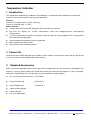
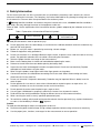
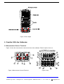
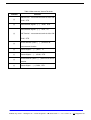
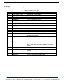
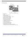
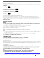
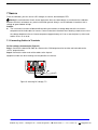
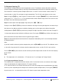
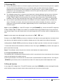
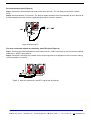
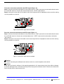
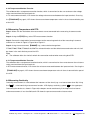
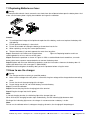
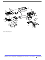
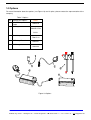
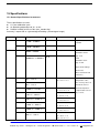
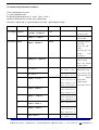
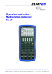
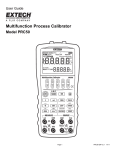
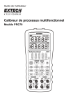
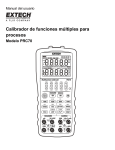
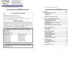
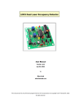
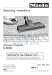
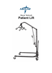
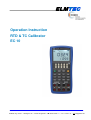
ELMTEC
Operation Instruction
RTD & TC Calibrator
EC 10
ELMTEC Ing. GmbH • Kattreppeln 28 • 38154 Königslutter • 05353 / 9545 - 0 •
www.elmtec.de • | [email protected]
Temperature Calibrator
1 Introduction
This temperature calibrator (the calibrator in the following) is a handheld, battery-operated instrument that
measures and sources electrical and physical parameters.
Features:
Measure: DC-voltage, ohm, Tc, RTD, continuity;
Source: DC-voltage, ohm, Tc, RTD;
Others features:
2-wire,3-wire,4-wire connection method for ohm and RTD measurement.
Big LCD can display the TC/RTD measurement value and voltage/resistance corresponding
simultaneously.
TC measurement/source terminals and built-in lead connector of same temperature (RJ compensation
with auto-reference joint point)
Room temperature monitoring under any operation
Measurement wave-filter function
Measurement manual-holding function
2 Contact Us
To purchase parts, obtain operation help or address of the vendor or service center nearest to you, please call
us or visit our web (see the bottom page of the Manual).
3
Standard Accessories
Make sure that the package contains all the accessories listed below. And if you find they are damaged or any
of them is missing, please contact the vendor from which you purchased the product as soon as possible.
Refer to the replacing part list in the Manual if you want to order the replacing parts.
One set of Industrial testing Lead (CL727220)
A set of Testing Lead
(Tp727110)
A set of Alligator clip
(CC807130)
A quick reference guide
A User's Manual
One Fuse 50mA/250V
ELMTEC Ing. GmbH • Kattreppeln 28 • 38154 Königslutter • 05353 / 9545 - 0 •
www.elmtec.de • | [email protected]
4 Safety Information
For the correct and safe use of the instrument, be sure to follow the cautionary notes stated in this manual
whenever handling the instrument. The Company shall not be held liable for any damage resulting from use of
the instrument in a manner other than prescribed in the cautionary notes.
Warning identifies conditions and actions that pose hazards to the user; a Caution identifies conditions
A
and actions that may damage the meter or the equipment under test.
Refer to Table 1 for the explanation of the international electric symbols adopted by the calibrator or the user’s
manual.
Table 1 Explanations of International Electrical Symbols
EARTH GROUND
WARNING
INFORMATION
Warning
To avoid possible electric shock or personal injury:
Do not apply more than the rated voltage, as marked on the calibrator, between terminals or between any
terminal and earth ground;
Before use, verify the meter’s operation by measuring a known voltage;
Follow all equipment safety procedures;
Do not use the meter if it is damaged. Before using the meter, inspect the case. Look for cracks or missing
plastic .Pay particular attention to the insulation surrounding the connectors;
Select the proper function and range for the measurement;
Make sure the battery door is closed and latched before operating the meter;
Remove test leads from the meter before opening the battery door;
Inspect the test leads for damaged insulation or exposed metal. Check test lead continuity. Replace
damaged test leads before using the meter;
When using the probes, keep fingers behind the finger guards on the probes;
Connect the common test lead before connecting the live test lead. When disconnecting test leads,
disconnect the live test lead first;
Do not use the meter if it operates abnormally. Protection may be impaired. When in doubt, have the
meter inspect;
Do not operate this instrument in areas where inflammable or explosive gases or vapor exists. It is
extremely hazardous to use the instrument under such environments;
Do not operate the meter around explosive gas, vapor, or dust;
Use only type 4 AAA batteries, properly installed in the meter case, to power the meter;
Do disconnect the testing lead before shifting to different source or measurement functions;
When servicing the meter, use only specified replacement parts.
To avoid false reading, which could lead to possible electric shock or personal injury, replace the batteries
) appears.
as soon as the low battery indicator (
Caution
To avoid possible damage to meter or to equipment under test:
Disconnect the power and discharge all high-voltage capacitors before testing resistance or continuity.
Use the proper jacks, functions, and ranges for the measurement or source operation.
ELMTEC Ing. GmbH • Kattreppeln 28 • 38154 Königslutter • 05353 / 9545 - 0 •
www.elmtec.de • | [email protected]
Figure 1 Entire Graph
5 Familiar With the Calibrator
5.1 Measurement/ Source Terminals
Figure 2 shows the measurement /source terminals of the calibrator. Table 2 explains their use.
Figure 2 Measurement/ Source Terminals
Figure 3 keys
ELMTEC Ing. GmbH • Kattreppeln 28 • 38154 Königslutter • 05353 / 9545 - 0 •
www.elmtec.de • | [email protected]
Table 2 Measurement/ Source Terminals
Terminal
Function
4W terminals : measurement terminal of the 4W
①
②
OHM、RTD
Measurement Signals(+):OHM、RTD
Measurement Signals(+):DCV、TC
③
3W Terminal:measurement terminal of the 3W
OHM、RTD
④
All the common (return ) (-)terminals of
measurement function
⑤
Source Signals:(+)DCV、TC
⑥
Source Signals:(-)OHM、RTD
⑦
All the common (return ) (-)terminals of source
function
⑧
Source Signal:(+)OHM、RTD
ELMTEC Ing. GmbH • Kattreppeln 28 • 38154 Königslutter • 05353 / 9545 - 0 •
www.elmtec.de • | [email protected]
5.2 Keys
Figure 3 shows keys of the calibrator. Table 3 explains their use.
Table 3 Functions of the keys
No.
Name
Function
1~5
Source value set key
Increment of source set point
6~10
Source value set key
Decrement of source set point
11
MEASURE key
Turn on or off measurement function
12
SOURCE key
Turn on or off source function
13
Power key
Turn on or off the power
14
Backlight key
Turn on or off the backlight
15
mV Key
Select measurement/source DC-voltage function
16
RTD Key
Select measurement/source RTD function
17
OHM Key
Select measurement/source OHM function
18
Tc Key
Select measurement/source Tc function
19
Key
Select measurement continuity function
20
RANGE Key
Select measurement/source range
21
RJ-ON Key
In TC measurement /source function, turn on or off the RJ
compensation function.
22
T.DISP Key
In TC/RTD measurement /source function, pressing the
key, convert the assistance display between room
temperature or mV/Ωvalue;
On other measurement/source function, pressing the key,
turn on or off room temperature display in assistance
display.
23
HOLD Key
Measured value holding
24
4/3/2W Key
In ohm/RTD measurement function, select 2W,3W or 4W
method.
25
AVG Key
Measuring average value
26
ZERO Key
Set the source value to default value
ELMTEC Ing. GmbH • Kattreppeln 28 • 38154 Königslutter • 05353 / 9545 - 0 •
www.elmtec.de • | [email protected]
5.3.Display Screen
Figure 4: shows a typical display screen
a:Measurement
b:Source
c:Measurement/Source resistance
d:Battery level indicator
e:Measurement/ Source function on
f: Measurement/ Source DC-voltage
function
g:Measurement/ Source Tc function
h:Measurement/ Source RTD function
i:Beeper of measurement continuity
j:Display –hold for measured value
k:Average value for measurement
l:4/3/2W for Measurement ohm/RTD function
m:Measurement/Source value
n:Unit of measured/sourced value
o:Reference Junction Compensation On
p:Types of TC measurement / source
q:Types of RTD measurement / source
r:room temperature/ Tc(mV) or RTD(Ω) subsection value
s:Unit of room temperature/ Tc(mV) or RTD(Ω) Unit of subsection value
ELMTEC Ing. GmbH • Kattreppeln 28 • 38154 Königslutter • 05353 / 9545 - 0 •
www.elmtec.de • | [email protected]
6 Before starting source/measurement
Operating Precautions
Precautions for Safe Use of the Instrument
When using the instrument for the first time, be sure to read the instructions given in Section Four
“Precautions for Safe Use of the Instrument.”
Do not open the instrument’s case.
Contact the vendor from which you purchased the instrument, for a service of inspecting or adjusting the
internal assembly.
In case of failure
Should the instrument begin to emit smoke, give off an unusual odor, or show any other anomaly,
immediately turn off the POWER key. If you are using an Charger, disconnect the plug from the wall outlet.
Also cut off power to the object under test that is connected to the input terminals. Then, contact the
vendor from which you purchased the instrument.
Charger
Use an Charger dedicated to the instrument. Avoid placing any load on the Charger, or prevent any
heat-emitting object from coming into contact with the adapter.
General Handling Precautions
Before carrying around the instrument turn off power to the object under test, and then the POWER key of
the instrument. If you are using an Charger, disconnect the power cord from the wall outlet. Finally, detach
all lead cables from the instrument. Use a dedicated carry case when transporting the instrument.
Do not bring any electrified object close to the input terminals, since the internal circuit may be destroyed.
Do not apply any volatile chemical to the instrument’s case or operation panel. Do not leave the
instrument in contact with any product made of rubber or vinyl for a prolonged period. Be careful not to let
a soldering iron or any other heat-emitting object come into contact with the operation panel, as the panel
is made of thermoplastic resin.
Before cleaning the instrument’s case or operation panel disconnect the power cord plug from the wall
outlet if you are using an Charger. Use a soft, clean cloth soaked in water and tightly squeezed to gently
wipe the outer surfaces of the instrument. Ingress of water into the instrument can result in malfunction.
If you are using an Charger with the instrument and will not use the instrument for a prolonged period,
disconnect the power cord plug from the wall outlet.
For handling precautions regarding the batteries, see “Installing or Replacing the Batteries”.
Never use the instrument with the cover of the battery holder opened.
Environmental Requirements
Use the instrument in locations that meet the following environmental requirements:
Ambient temperature and humidity
Ambient temperature range: 0 to 50℃
Ambient humidity range: 20 to 80% RH. Use the instrument under non-condensing condition.
Flat and level locations
ELMTEC Ing. GmbH • Kattreppeln 28 • 38154 Königslutter • 05353 / 9545 - 0 •
www.elmtec.de • | [email protected]
Do not use the instrument in locations that are
Exposed to direct sunlight or close to any heat source.
Exposed to frequent mechanical vibration.
Close to any noise source, such as high-voltage equipment or motive power sources.
Close to any source of intensive electric or electromagnetic fields.
Exposed to large amounts of greasy fumes, hot steam, dust or corrosive gases.
Exposed to unstable or a risk of explosion due to the presence of flammable gases.
Note:
Use the instrument under the following environmental conditions if precise source or measurement is your
requirement:
Ambient temperature range: 23±5°C;
Ambient humidity range: 20 to 80% RH(non-condensing)
When using the instrument within a temperature range of 0 to 18°C or 28 to 50°C, add a value based on
the temperature coefficient shown in Chapter 18“Specifications” to the given accuracy rating.
When using the instrument at an ambient humidity of 30% or lower, prevent electrostatic charges from
being produced, by using an antistatic mat or any other alternative means.
Condensation may occur if you relocate the instrument from places with low temperature and humidity to
places with high temperature and humidity, or if the instrument experiences any sudden temperature
change. In that case, leave the instrument under the given ambient temperature for at least one hour to
ensure that the instrument is free from condensation, before using the instrument.
Installing or Replacing the Batteries
Warning
To avoid electrical shock, always remove the source or measurement lead cables from the object under test,
as well as from the instrument itself.
Caution
To avoid the risk of fluid leakage or battery explosion, install batteries with their positive and negative
electrodes correctly positioned.
Do not short-circuit the batteries.
Do not disassemble or heat the batteries or throw them into fire.
When replacing batteries, replace all of the four batteries at the same time with new ones from the same
manufacturer.
If the instrument will not be used for a prolonged period, remove the batteries from the instrument.
Step 1: Remove the lead cables and charger and turn off the calibrator before you begin installing batteries.
Step 2: Remove the battery holder cover by sliding it in one-quarter counterclockwise direction and turn off the
calibrator.
Step 3: Install four alkaline batteries of same type in the battery holder with their positive and negative
electrodes positioned correctly as indicated on the holder.
Step 4: After replacement, reattach the battery holder cover.
ELMTEC Ing. GmbH • Kattreppeln 28 • 38154 Königslutter • 05353 / 9545 - 0 •
www.elmtec.de • | [email protected]
Indication of Battery Level
The battery replacement indicator shows the battery level in five steps according to the measured voltage of
the batteries.
Full battery:
The battery level is below 50% full:
The battery level is below 25% full:
Low battery:
The dictation flashes in sequence when getting charged.
Note that the battery replacement indicator is driven by directly measuring the battery voltage when the
calibrator is in actual operation. Consequently, the indicator may read differently depending on the battery load
condition (e.g., the load condition of the source output or on/ off state of the measurement function) if the
batteries are too low.
Connecting the Charger
Warning
Make sure the voltage of the AC power source matches the rated supply voltage of the Charger, before
connecting the Charger to the AC power source.
Do not use any Charger other than the dedicated Charger from the Company.
Do not charge non Ni-Cd, Ni-MH batteries or wasted batteries.
Step 1: Make sure the calibrator is turned off.
Step 2: Insert the plug of the optional Charger into the Charger connection jack.
Note
Turn off the calibrator before connecting or disconnecting the Charger from AC power, plugging in/out the
Charger connection jack.
Plug out the Charger from the Charger connection jack of the calibrator when discharging.
Do not charge the calibrator without any battery in.
Turning On the Power
Pressing the Power key once when the power is off turns on the calibrator.
Pressing the Power key for 2 seconds turns off the calibrator.
Automatic Power-off
When the calibrator is running on batteries and no key is operated for approximately ten minutes, the calibrator
turns off automatically. The automatic power-off time could be reset in the factory default parts, see Chapter 10
“Factory Default”.
Turning On/Off the Backlight
Pressing the key turns on the backlight, while pressing the key once again turns it off. This feature makes it
easier for you to view the LCD when operating the calibrator in dark places or when carrying out source or
measurement. Battery life shortens when the calibrator is operated on batteries.
Note
The backlight automatically turns off after 10 seconds. Press the key once more to relight it.
The time could be reset in the factory default parts, see Chapter 10 “Factory Default”.
ELMTEC Ing. GmbH • Kattreppeln 28 • 38154 Königslutter • 05353 / 9545 - 0 •
www.elmtec.de • | [email protected]
7 Source
From the calibrator, you can source a DC voltage, resistance, thermocouple, RTD.
WarningTo avoid electrical shock, do not apply more than the rated voltage, as marked on the calibrator,
between terminals or between any terminal and earth ground. Always use the calibrator in locations with a
voltage to ground below 30 Vpk.
Caution
The instrument has been calibrated without taking into account a voltage drop due to the resistance
component of the lead cables for source. Care must be taken therefore when drawing a load current since
the voltage drop due to the resistance component (approximately 0.1 Ω on a round-trip basis) of the lead
cables serves as an error.
7.1 Connecting Cables to Terminals
For DC voltage, thermocouple (Figure 5)
Step 1: Connect the black lead cable for source to the COM output terminal and the red lead cable to the
“mVTc” output terminal.
Step 2: Connect the other ends of the cables to the input of
equipment under test while making sure the polarities are correct.
Figure 5: Sourcing DC voltage, TC
ELMTEC Ing. GmbH • Kattreppeln 28 • 38154 Königslutter • 05353 / 9545 - 0 •
www.elmtec.de • | [email protected]
For resistance and RTD signal (Figure 6)
Step 1: Connect black lead cables for source to the black terminal of Ω、RTD and the red lead cable to the red
terminal of Ω、RTD.
Step 2: Connect the other ends of the cables to the input of equipment under test while making sure the
polarities are correct.
Figure 6 Sourcing Resistances and RTD
7.2 Sourcing DC Voltage
Step 1: Using the〔
〔mV〕
〕key to select DC voltage source function, select the desired range from 100mV,
1000mV by pressing the〔
〔RANG〕
〕key. The default value and unit of the selected source function and range
shall be displayed in the main districts part of the LCD.
Step 2: Set the output value digit by digit using 〔〕
〕/〔
〔〕
〕keys.
Each pair of 〔〕
〕/〔
〔〕
〕keys corresponds to each digit of the LCD reading. Each press of the 〔〕
〕/〔
〔〕
〕
key increases or decreases the digit. Increasing the digit from 9 or decreasing it from 0 causes the digit to
overflow or underflow, allowing you to set the output value without interruption. Holding down the 〔〕
〕/〔
〔〕
〕
key continuously changes the digit in question. And the value won’t change if it is increased or decreased to
the Maxim or Minimum value. Pressing the〔
〔ZERO〕
〕key initializes the output set point to the default value (0).
Step 3: The calibrator sources the DC-voltage signal between the output terminals.
ELMTEC Ing. GmbH • Kattreppeln 28 • 38154 Königslutter • 05353 / 9545 - 0 •
www.elmtec.de • | [email protected]
7.3 Sourcing Resistance
Firstly, the calibrator sources a resistance signal by receiving the resistance-measuring current I supplied
from the device being calibrated (such as a resistance meter) and then delivering the voltage V
proportional to the preset resistance R between the output terminals, and thus producing the equivalent
resistance R =V/I. Consequently, the calibrator sources the signal correctly only for such devices that
employ this method of measurement.
The allowable range of the resistance measuring current I that the calibrator receives from a resistance
measuring device under calibration is rated as 0.1 mA to 3 mA. To ensure accuracy, the resistance
measuring current I from the device under calibration shall be strictly confined within the range. For further
details, see Chapter 17, “Specification”.
Any resistance signal being sourced does not include the resistance component of the lead cables for
source. The whole resistance, when measured at the ends of the lead cables for source, is given by
adding the resistance of the lead cables (approximately 0.1Ω on a round-trip basis) to the sourced
resistance signal. For source of precise resistance signals, use three-wire or four-wire connection.
If capacitance between the terminals of a device under calibration is greater than 0.1ųF, the calibrator may
fail to source correct resistance signals.
Step 1: Using the〔OHM〕
〕key to select Ohm function. Using the 〔RANGE〕
〕key, select the desired range. The
selected function and the default range source value and unit shall be shown in the main districts part of the
LCD.
Step 2 :Set the output value digit by digit using each pair of〔
〔〕
〕/〔
〔〕
〕keys.
Each pair of〔
〔〕
〕/〔
〔〕
〕keys corresponds to each digit of the LCD reading. Each press of the〔
〔〕
〕/〔
〔〕
〕
key increases or decreases the digit. Increasing the digit from 9 or decreasing it from 0 causes the digit to
overflow or underflow, allowing you to set the output value without interruption. Holding down the〔
〔〕
〕/〔
〔〕
〕
key continuously changes the digit in question. And the value won’t change if it is increased or decreased to
the Maxim or Minimum value. Pressing the〔
〔ZERO〕
〕key initializes the output set point to the default value(0).
Step 3: The calibrator sources the preset resistance value between the output terminals.
ELMTEC Ing. GmbH • Kattreppeln 28 • 38154 Königslutter • 05353 / 9545 - 0 •
www.elmtec.de • | [email protected]
7.4 Simulate Sourcing TC
The calibrator is designed with an internal temperature sensor. To calibrate a device with built-in reference
junction temperature compensation by sourcing a thermoelectromotive force with the calibrator without using
non-external 0℃ reference junction compensation means, use the RJ sensor function. Select simulate TC
source function, in which RJ senor goes on work automatically. The “RJ-ON” mark displays on the screen.
Step 1: Using the〔
〔TC〕
〕key, select simulate TC source function. Using the〔
〔RANGE〕
〕 key, select the desired
range from K, E, J, T, B, N, R, S, L, U. The selected function and the default range source value and unit shall
be shown in the main districts part of the LCD.
Step 2 :Set the output value digit by digit using each pair of〔
〔〕
〕/〔
〔〕
〕keys.
Each press of the〔
〔〕
〕/〔
〔〕
〕key increases or decreases the digit. Increasing the digit from 9 or decreasing it
from 0 causes the digit to overflow or underflow, allowing you to set the output value without interruption.
Holding down the〔
〔〕
〕/〔
〔〕
〕key continuously changes the digit in question. And the value won’t change if it
is increased or decreased to the Maxim or Minimum value. Pressing the〔
〔ZERO〕
〕key initializes the output set
point to the default value(the default value of a typical B type is 600℃).
Step 3: A thermoelectromotive force based on the temperature detected by the RJ sensor develops between
the output terminals.
Note:
If you don’t need the reference junction compensation, press the〔RJ-ON〕
〕key to shut off. The calibrator source
a value with using external 0℃ reference junction compensation means, and the “RJ-ON” mark vanishes.
Press the〔RJ-ON〕
〕key once more to start the reference junction compensation and the “RJ-ON” mark displays
on the screen.
Tips:
The temperature unit is defaulted as ℃.To convert into ℉,see Chapter 10 “Factory Default” .
7.4.1 Temperature Monitor Function
The calibrator offers a temperature monitor function, which is convenient for the user to observe the voltage
value sourced between the output terminals in TC source function.
In TC source function, the assistance district of the LCD shows the voltage value sourced between the output
terminals,(varies responding to the changes of the reference junction compensation). Pressing the〔
〔T.DISP〕
〕
key once more, the assistance district of the LCD shows the preset room temperature value.
ELMTEC Ing. GmbH • Kattreppeln 28 • 38154 Königslutter • 05353 / 9545 - 0 •
www.elmtec.de • | [email protected]
7.5 Sourcing RTD
Firstly, the calibrator sources a resistance signal by receiving the resistance-measuring current I supplied
from the device being calibrated (such as a resistance meter) and then delivering the voltage V
proportional to the preset resistance R between the output terminals, and thus producing the equivalent
resistance R =V/I. Consequently, the calibrator sources the signal correctly only for such devices that
employ this method of measurement.
The allowable range of the resistance measuring current I that the calibrator receives from a resistance
measuring device under calibration is rated as 0.1 to 3 mA at PT100,Cu10,Cu50, 0.05 to 0.3 mA at
PT200,PT500,PT1000.To ensure accuracy, the resistance measuring current I from the device under
calibration shall be strictly confined within the range. For further details, see Chapter 17, “Specification”.
Any resistance signal being sourced does not include the resistance component of the lead cables for
source. The whole resistance, when measured at the ends of the lead cables for source, is given by
adding the resistance of the lead cables (approximately 0.1Ω on a round-trip basis) to the sourced
resistance signal.
Step 1: Using the〔
〔RTD〕
〕key, select RTD function. Using the〔
〔RANGE〕
〕key, select a desired RTD range from
PT100, PT200, PT500, PT1000, Cu10, Cu50. The selected function and the default range source value and
unit shall be shown in the main district of the LCD and the type of the RTD shall be shown in middle port of the
LCD.
Step 2 :Set the output value digit by digit using each pair of〔
〔〕
〕/〔
〔〕
〕keys.
Each press of the〔
〔〕
〕/〔
〔〕
〕key increases or decreases the digit. Increasing the digit from 9 or decreasing it
from 0 causes the digit to overflow or underflow, allowing you to set the output value without interruption.
Holding down the〔
〔〕
〕/〔
〔〕
〕key continuously changes the digit in question. And the value won’t change if it
is increased or decreased to the Maxim or Minimum value. Pressing the〔
〔ZERO〕
〕key initializes the output set
point to the default value(0).
Step 3: The calibrator sources the preset resistance value between the output terminals.
7.5.1 Temperature Monitor Function
The calibrator offers a temperature monitor function, which is convenient for the user to observe the resistance
value sourced between the output terminals.
In RTD source function, LCD shows the resistance value sourced between the output terminals. Pressing the
〔T.DISP〕
〕key once more, the assistance districts of the LCD shows the preset room temperature value.
7.6 Zero-off function
In any range of DC voltage, ohm, TC and RTD functions, pressing the〔ZERO〕
〕key selects clearing off function,
which initializes the preset source value for the convenience of user to reset source value.
ELMTEC Ing. GmbH • Kattreppeln 28 • 38154 Königslutter • 05353 / 9545 - 0 •
www.elmtec.de • | [email protected]
8 Measurement
From the calibrator, you can measure a DC voltage, resistance, thermocouple, RTD and continuity.
Warning
In an application where the calibrator is used together with the supplied lead cables for measurement, the
allowable voltage to ground of the input terminals is 30 Vpeak maximum. To avoid electrical shock, do
NOT use the calibrator at any voltage exceeding the maximum voltage to ground.
The allowable voltage to ground when the supplied thermocouple convertor is attached to the input
terminals is 30V peak maximum. To avoid electrical shock, do not use the terminal adapter for measuring
any circuit voltage exceeding the maximum voltage to ground.
Tips:
With the〔
〔HOLD〕
〕key, you can hold the measured value.
The reading of a measured value is updated differently responding to different measurement function.
LCD shows “ - - - - - “on the upper part when shifting the range. If the input is over ranged, the measured
value on the LCD reads as “oL”.
8.1 Connecting Cables to Terminals
For DC voltage measurement (Figure 7)
Step 1: Connect the black lead cable for measurement to
the “COM” input terminal and the red lead cable to the ”mVTc3W” input terminal.
Step 2: Connect the other end of the cable to the measuring terminals of equipment under test while making
sure the polarities are correct.
Figure 7 Measuring DC voltage
ELMTEC Ing. GmbH • Kattreppeln 28 • 38154 Königslutter • 05353 / 9545 - 0 •
www.elmtec.de • | [email protected]
For thermocouple signal (Figure 8)
Step 1: Connect the thermocouple convertor to the input terminals. This will help you connect the cables
easily.
Step 2: Connect between TC terminals. The positive output lead wire of the thermocouple to the H terminal of
the thermocouple convertor and the negative output lead wire to the L terminal.
Figure 8 Measuring TC
Two wire connection method for continuity, ohm/RTD signal (Figure 9)
Step 1: Connect one black lead cable for measurement to the “COM” input terminal and Connect the red lead
cable to the ” ΩRTD” input terminal.
Step 2: Connect the two clips of the cables to the measuring terminals of equipment under test while making
sure the polarities are correct.
Figure 9 Measuring continuity ,ohm/RTD signal with 2w method
ELMTEC Ing. GmbH • Kattreppeln 28 • 38154 Königslutter • 05353 / 9545 - 0 •
www.elmtec.de • | [email protected]
Three wire connection method for ohm/RTD signal (Figure 10)
Step 1: Connect one black lead cable for measurement to the “COM” input terminal and another black lead to
the “mVTc3W” terminal. Connect the red lead cable to the ” ΩRTD” input terminal.
Step 2: Connect the three clips of the cables to the measuring terminals of equipment under test while making
sure the polarities are correct.
Figure 10 ohm/RTD signal with 3w method
Four wire connection method for ohm/RTD signal (Figure 11)
Step 1: Connect one black lead cable for measurement to the “COM” input terminal and another black lead to
the “mVTc3W” terminal. Connect one red lead cable to the ” ΩRTD” input terminal and another red lead to
“4W” terminal.
Step 2: Connect the four clips of the cables to the measuring terminals of equipment under test while making
sure the polarities are correct.
Figure 11 ohm/RTD signal with 4w method
Warning
Before connecting the calibrator to the device under test, cut off the power to the device.
Warning
If you make a mistake in wiring or in the operating procedure in this measurement task, there will be a danger
of not only damage to the instrument but also personal injury due to electrical shock. Exercise the utmost care
when carrying out the measurement task.
ELMTEC Ing. GmbH • Kattreppeln 28 • 38154 Königslutter • 05353 / 9545 - 0 •
www.elmtec.de • | [email protected]
8.2 Measuring DC Voltage
Step 1: Make sure the lead cables for measurement are not connected to the measuring instrument under
test.
Step 2: Using the〔
〔mV〕
〕key, select DC Voltage measurement function.
Step 3: Connect the lead cables for measurement to the measuring terminals of the measuring instrument
under test.
Step 4: Using the〔
〔RANGE〕
〕key, select a desired range from 50mV, 500mV. The selected function and the
measured value and unit shall be shown in the main districts part of the LCD.
8.3 Measuring Resistance
Step 1: Make sure the lead cables for measurement are not connected to the measuring instrument under
test.
Step 2: Using the〔
〔OHM〕
〕, select resistance measurement function.
Step 3: Connect the lead cables for measurement to the measuring terminals of the measuring instrument
under test as shown in Figure 9, Figure 10 or Figure 11.
Step 4: Using the measurement〔
〔RANGE〕
〕key, select the desired range from 500Ω,5K.The selected function
and the measured value and unit shall be shown in the main districts part of the LCD.
8.4 Measuring Temperature with Thermocouple (TC)
Note:
Any voltage higher than 30Vpk won’t work on the measured circuit if applying the thermocouple convertor to
the given input terminal.
Step 1: Make sure the lead cables for measurement are not connected to the measuring instrument under
test.
Step 2: Using the 〔TC〕
〕key, select TC measurement function. Using the measurement 〔RANGE〕
〕key, select
the desired range from K, E, J, T, B, N, R, S, L,U.
Step 3: Connect the thermocouple convertor to the jack under test as shown in Figure 8.The selected function
and the measured value and unit shall be shown in the main districts part of the LCD.
Tips:
If there has been a sudden change in the operating ambient temperature of the calibrator, wait until the
built-in reference junction compensation stabilizes. Avoid using the calibrator in locations exposed to wind
from such apparatus as an airconditioner.
8.4.1 Using RJ sensor
Select TC measurement function, in which RJ senor goes on work automatically, press〔RJ-ON〕
〕key to shut off.
Both the “RJ-ON” mark and the environmental temperature display vanish. Press the〔
〔RJ-ON〕
〕key once more
to start the reference junction compensation and the “RJ-ON” mark displays on the middle of the screen, and
the environmental temperature displays on the screen.
ELMTEC Ing. GmbH • Kattreppeln 28 • 38154 Königslutter • 05353 / 9545 - 0 •
www.elmtec.de • | [email protected]
8.4.2 Temperature Monitor Function
The calibrator offers a temperature monitor function, which is convenient for the user to observe the voltage
value measured from the input terminals.
In TC measurement function, LCD shows the voltage value measured between the input terminals. Pressing
the〔
〔T.DISPLAY〕
〕key again, LCD shows the measured room temperature value in the assistance districts part
of the LCD.
8.5 Measuring Temperature with RTD
Step 1: Make sure the lead cables for measurement are not connected to the measuring instrument under
test.
Step 2: Using the〔
〔RTD〕
〕key, select RTD measurement function.
Step 3: Connect the lead cables for measurement to the measuring terminals of the measuring instrument
under test as shown in Figure 9, Figure 10 or Figure 11.
Step 4: Using the measurement〔
〔RANGE〕
〕key, select a desired range from
PT100,PT200,PT500,PT1000,Cu10,C50.The selected function and the default measured value and unit shall
be shown in the main districts part of the LCD.
Tips:
The calibrator offers the 2-wire/3-wire/4-wire connection method when measuring ohm/RTD.
8.5.1 Temperature Monitor Function
The calibrator offers a temperature monitor function, which is convenient for the user to observe the resistance
value measured from the input terminals.
In RTD measurement function, LCD shows the resistance measured between the input terminals. Pressing the
〔T.DISPLAY〕
〕key again, LCD shows the measured room temperature value in the assistance districts part of
the LCD.
8.6 Measuring Continuity
Continuity measurement is used to detect the intactness of the circuit (e.g. a resistance lower than 50). Using
the〔
〔
〕, select continuity measurement function. LCD displays continuity symbol “
”on the upper part.
Connecting the devices as shown in Figure 9,the beeper sounds continuously if the loop circuit resistance
under measurement is less than 50Ω,and LCD shows the present measured resistance value.
ELMTEC Ing. GmbH • Kattreppeln 28 • 38154 Königslutter • 05353 / 9545 - 0 •
www.elmtec.de • | [email protected]
8.7 Measurement-filtering function
Selecting measurement-filtering function stabilizes the measured value displayed on LCD.
In DCV, OHM, TC, RTD function, pressing the〔
〔AVG〕
〕key causes calculation of the average of the samples.
LCD shows the “AVG” symbol. Repressing the〔
〔AVG〕
〕key cancels the calculation and the “AVG” symbol
disappears.
8.8 Measured Value holding function
Apart from the continuity measurement functions, the reading-hold function can also be used to preserve the
current measured value on the main districts part of LCD, which consequently doesn’t refresh the measured
value.
Pressing the〔
〔HOLD〕
〕key selects reading-hold mode, and LCD displays “HOLD” symbol. To cancel the
selection, press the〔
〔HOLD〕
〕key again and the “HOLD” symbol disappears.
9 Environmental Temperature Test
The calibrator can measure the surrounding environmental temperature. After turning on the calibrator, to
observe the surrounding environment, pressing the〔
〔T.DISP〕
〕key causes LCD displays the room temperature
value and the unit in the assistance districts part of the LCD. Repressing the〔
〔T.DISP〕
〕key cancels the room
temperature value.
ELMTEC Ing. GmbH • Kattreppeln 28 • 38154 Königslutter • 05353 / 9545 - 0 •
www.elmtec.de • | [email protected]
10 Factory Default
You can reset the factory default of the calibrator.
When turning on the calibrator, pressing the〔
〔HOLD〕
〕key immediately to enter the default set.
10.1 Setting Auto -power off time
Step 1: When entering the default set, LCD displays “AP.OFF” symbol on the upper part, indicating automatic
power- off setting mode.
Step 2: Set the time within 0-60 minute range by using the second pair of 〔〕
〕〔
/ 〕
〕counting from right to left.
Each press of the〔〕
〕/〔〕
〕key causes 10 -minute increments or 10- minute decrement with constant setting.
Constant press of the key causes increments or decrement of the value in sequence. The value won’t change
when reaching the maximum or minimum value. The time unit is minute.
Step 3: Pressing the〔
〔SOURCE〕
〕key, LCD displays “SAVE” symbol on the upper part for 1s.
Tips:
Zero default value (0) represents no automatic power-off function.
10.2 Setting Backlight time
Step 1: Pressing the〔
〔MEASURE〕
〕key ,LCD displays “BL.OFF” symbol on the upper part, indicating backlight
time setting mode.
Step 2: Set the time by using the pair of 〔〕
〕/〔
〔〕
〕. And the unit is second.
Each pair of〔
〔〕
〕/〔
〔〕
〕keys corresponds to each digit of the LCD reading. Each press of the〔
〔〕
〕/〔
〔〕
〕
key increases or decreases the digit. Increasing the digit from 9 or decreasing it from 0 causes the digit to
overflow or underflow, allowing you to set the output value without interruption. Holding down the〔
〔〕
〕/〔
〔〕
〕
key continuously changes the digit . And the value won’t change if it is increased or decreased to the Maxim or
Minimum value. The setting range is confined within 0-3600 seconds.
Step 3: Pressing the〔
〔SOURCE〕
〕key, LCD displays “SAVE” symbol on the upper part for 1sec.
Tips:
When the default value is 0, the backlight won’t be off automatically if turned on except that you turn it off
manually.
ELMTEC Ing. GmbH • Kattreppeln 28 • 38154 Königslutter • 05353 / 9545 - 0 •
www.elmtec.de • | [email protected]
10.3 Setting temperature unit
Step 1: Pressing the〔
〔MEASURE〕
〕key ,LCD displays “TEM.U” symbol on the upper part, indicating
temperature unit setting mode.
Step 2: Shifting between the ℃ and ℉ by using the right pair of 〔〕
〕/〔
〔〕
〕.
Step 3: Pressing the〔
〔SOURCE〕
〕key, LCD displays “SAVE” symbol on the upper part for 1s.
10.4 Setting frequency
Step 1: Pressing the〔
〔MEASURE〕
〕key ,LCD displays “FRSET” symbol on the upper part, indicating frequency
setting mode.
Step 2: Shifting between the 50Hz and 60Hz by using the right pair of 〔〕
〕/〔
〔〕
〕.
Step 3: Pressing the〔
〔SOURCE〕
〕key, LCD displays “SAVE” symbol on the upper part for 1s.
10.5 Factory default
Step 1: Pressing the〔
〔MEASURE〕
〕key ,LCD displays “FACRY” symbol on the upper part, indicating factory
default.
Step 2: Pressing the〔
〔SOURCE〕
〕key, LCD displays “SAVE” symbol on the upper part for 1s. All settings are
defaulted as below:
AP.OFF: 10min.
BL.OFF: 10sec.
TMP.U: ℃.
FRSET: 50 Hz.
Tips:
Any change of setting to the above-mentioned function, press the 〔SOURCE〕
〕 key to save the value. Any
press of the〔
〔SOURCE〕
〕key saves the nearest setting value.
ELMTEC Ing. GmbH • Kattreppeln 28 • 38154 Königslutter • 05353 / 9545 - 0 •
www.elmtec.de • | [email protected]
11 Replacing Batteries or fuse:
Warning
To avoid possible electric shock, remove the test leads from the calibrator before open the battery door. And
make sure the battery door is tightly closed before turning on the calibrator.
Caution
To avoid possible linkage of the liquid and explosion of the battery, make sure to place the battery with
right polarity.
Do not operate the battery in short-circuit.
Do not disassemble or heating the battery or throw them into the fire
When replacing, use only four same specified ones.
Take out the battery if you don’t operate the meter for a long time.
Step 1: Remove the test leads and Charger before
Figure 16 Replacing batteries and fuses
replacing batteries or fuse, and turn off the meter.
Step 2: Remove the protector as shown in Figure 16. With a standard blade hand screwdriver, turn each
battery door screw a quarter counterclockwise to remove the battery door.
Step 3:Replace with four new AAA alkaline batteries under the instructions shown on the battery door. Or
replace the blown fuses with same type F1 (50mA/250V).
Step 4:Reinstall and tighten the battery door, put on the protector before using the meter.
12 How to use the charger
Warning
The charger could be used only to specified product.
Make sure the voltage of the AC power is same with the given voltage of the charger before connecting
them.
Do not shut circuit the output plug of the charger.
Do not charge non-Ni-Cd, non-Ni-MH battery or wasted battery.
Step 1:Turn off the calibrator.
Step 2:Connect the plug into the charging jack of the terminal.
Step 3:Plug the charger into the AC power.
Note:
In normal charging function, the indicating light of the charger lights on.
When finished, the charging function stops automatically, and the indicating light becomes dark.
Blinking of the indicating light means the charger is not connected or no battery is inside.
Note:
Do not use the calibrator when it undergoes charging, otherwise, the charging will be prolonged.
ELMTEC Ing. GmbH • Kattreppeln 28 • 38154 Königslutter • 05353 / 9545 - 0 •
www.elmtec.de • | [email protected]
13 Maintenance
13.1 cleaning the calibrator
Warning
To avoid electrical shock or damaging the meter, serve the meter only by the replacement parts specified and
never get water inside the case.
Caution
To avoid damaging the plastic lens and case, do not use solvents or abrasive cleansers.
Clean the Calibrator with a soft cloth dampened with water or water and mild soap.
13.2 Calibration or Sending to the Service Center
Calibration, maintenance or repair work unmentioned in this manual should be undertaken by the experienced
worker. If the meter operates abnormally, inspect the batteries first and replace them if necessary.
If you suspect that the meter has failed, review this manual to make sure you are operating it correctly. If
the meter still fails to operate properly, pack it securely (in its original container if available) and forward
it, postage paid, to the nearest Service Center. The company assumes NO responsibility for damage in
transit.
The Company guarantees a rapid repair and maintenance and delivers the meter back as soon as
possible. Please refer to the Warranty. If the warranty is due, you will be billed for the maintenance and
repair work. If the calibrator or the pressure module is not within the Warranty range, you can contact
the warranted service center for enquiring about the expenditure. Please refer to the Chapter “Contact
Us” to find a warranted service center.
13.3 Replacement of Parts
All the types of parts are listed in Table 6, see Figure 17 as reference.
Table 6. Replacing parts
Item
Instruction
Quantity
Item
Instruction
Quantity
1
Top panel
1
16
Spring A
1
2
plastic lens
1
17
Spring B
1
3
Rubber Key
1
18
Spring C
3
4
Terminal Wrapper
8
19
AAA Alkaline battery
4
5
Terminal Gasket
8
20
Tilt-stand
1
6
LCD Frame
1
21
Screw M3*16
4
7
LCD
1
22
Battery Door
1
8
Backlight Panel
1
23
Plastic Screw
2
9
Conductive Rubber
wire
2
24
10
LCD Circuit Panel
1
25
Sponge:length×width×height=40×6×6
Sponge:length×width×height=48×10×
1
1
2.5
11
Screw M3*8
4
12
Terminal Cover
1
13
Cover Door
1
14
Main Circuit Panel
1
15
Bottom Panel
1
26
Outer Protector
ELMTEC Ing. GmbH • Kattreppeln 28 • 38154 Königslutter • 05353 / 9545 - 0 •
1
www.elmtec.de • | [email protected]
Figure 17 Replacing parts
ELMTEC Ing. GmbH • Kattreppeln 28 • 38154 Königslutter • 05353 / 9545 - 0 •
www.elmtec.de • | [email protected]
14 Options
For more information about the options (see Figure 18) and its price, please contact the representative of the
company.
Table 7 Options
No.
Name of the Options
Mode
1
CALCT Temperature
Probe
A000019
2
TC Plug
R/S/K/E/J/T/N/
B/L/U
3
Test Hoop
4
CA Battery Parcel
A000021
5
CA Charger
A000020
TP907110
Figure 18 Options
ELMTEC Ing. GmbH • Kattreppeln 28 • 38154 Königslutter • 05353 / 9545 - 0 •
www.elmtec.de • | [email protected]
15 Specifications
15.1 General Specifications for measure
These specifications assume:
A 1-year calibration cycle
An operating temperature of 18℃ to 28℃
Relative humidity of 35% to 70% (non_condensing)
Accuracy is expressed as ± (percentage of reading + percentage of range).
F Function
DCV
Reference
50mV
500mV
OHM
500Ω
5KΩ
Range
-5.000~55.000mV
-50.00~550.00mV
0.00Ω~550.00Ω
0.0000 kΩ~5.5000 KΩ
Resolution
Accuracy
Remark
1 µV
0.02 + 0.02
Input Resistance
100 MΩ
10 µV
0.02 + 0.01
0.01 Ω
0.05 + 0.02
500 Ω:
Excitation current:
0.1 Ω
app. 1mA
0.05 + 0.02
5 kΩ:
Excitation curren:
app. 0.1mA
Open Circuit Voltage:
about 2.5V;
Does not include lead
resistance;
TC
R
S
K
E
J
T
N
B
0°C~1767°C
1 °C
0~500 °C: 1.8 °C
By using ITS-90
500~1767°C: 1.5 °C
temperature scale;
The accuracy does not
0°C~1767°C
-100.0°C~1372.0°C
include the error of
0.1 °C
-50.0 °C~850.0 °C
internal temperature
0.0~1372.0 ℃ : 0.8 ℃
compensation caused
-50.0~0.0 ℃ : 0.9 ℃
by a sensor;
0.0~850.0 ℃: 1.5 ℃
-60.0~0.0 ℃ : 1.0 ℃
-60.0 °Cc~1120.0 °C
0.0~1120.0 ℃: 0.7 ℃
-100.0~0.0 ℃ : 1.0 ℃
-100.0 °C~400.0 °C
0.0~400.0 ℃: 0.7 ℃
-200.0~0.0 ℃ : 1.5 ℃
-200.0 °C~1300.0 °C
600 °C~1820 °C
-100.0~0.0 ℃ : 1.2 ℃
0.0~1300.0 ℃: 0.9 ℃
1 °C
600~800 ℃: 2.2 ℃
800~1000 ℃: 1.8 ℃
1000~1820 ℃: 1.4 ℃
ELMTEC Ing. GmbH • Kattreppeln 28 • 38154 Königslutter • 05353 / 9545 - 0 •
www.elmtec.de • | [email protected]
L
U
RTD
Pt100
385
Pt1000
385
Pt200
385
-60 °C~900 °C
-100 °C~600 °C
-200.0 °C~800.0 °C
-200.0 °C~630.0 °C
0.1 °C
-60.0~0.0 ℃ : 0.7 ℃
0.0~900.0 ℃: 0.5 ℃
0.1 °C
-100.0~0.0 ℃ : 0.7 ℃
0.0~600.0 ℃: 0.5 ℃
0.1 °C
0.1 °C
-200.0~0.0 °C: 0.5 °C
By using temperature
0.0 °C~400.0°C: 0.7 °C
scale ITS-90.
400.0~800.0 °C: 0.8 °C
Does not include lead
-200.0~100.0℃: 0.8 ℃
resistance. Assuming all
100.0~300.0 ℃: 0.9 ℃
three RTD leads are
300.0~630.0℃: 1.0 ℃
matched for 3-w input.
-200.0~100.0 ℃: 0.8 ℃
-200.0 °C~630.0 °C
100.0~300.0 ℃: 0.9 ℃
300.0~630.0 ℃: 1.0 ℃
Pt500
385
Cu10
Cu50
CONT.
500Ω
-200.0 °C~630.0 °C
-100.0 °C ~260.0 °C
0.1 °C
0.7 ℃
-50.0 °C~150.0 °C
≤50Ω sound
1.8 ℃
Excitation current :
0.01Ω
app. 1mA
Other feature:
Rate: 2 Readings per Second about
DCV
Normal Mode Rejection Ratio (NMRR) ≥60dB (at 50Hz or 60Hz)
Common Mode Rejection Ratio (CMRR) ≥120dB (at 50Hz or 60Hz)
Temperature Coefficient: 0.1 times the applicable accuracy specification per degree C for
5 °C to 18 °C and 28 °C to 50 °C
The range of the internal temperature compensation sensor is from -0 ℃ to 50 ℃, compensation
error≤±0.5 °C
The accuracy of the temperature probe: ±0.2℃. The range of the measured temperature is form
-20℃-100℃.
Maximum voltage between VΩHz terminal and COM terminal: 30 Vpk
ELMTEC Ing. GmbH • Kattreppeln 28 • 38154 Königslutter • 05353 / 9545 - 0 •
www.elmtec.de • | [email protected]
15.2 General Specifications for Source
These specifications assume:
A 1-year calibration cycle
An operating temperature of 18℃ to 28℃ (64.4℃~82.4℃)
Relative humidity of 35% to 70% (non_condensing)
Accuracy is expressed as ± (percentage of set value + percentage of range)
Function
Reference
DC voltage
100 mV
1000 mV
Resistance
400 Ω
Range
-10.000~110.000 mV
-100 mV~1100 mV
0.00 Ω~400.00 Ω
Resolution
Accuracy
Remark
1 µV
0.02 + 0.01
Maximum output
current: 0. 5mA
10 µV
Maximum
0.02 + 0.01
output
current: 2mA
0.01 Ω
Excitation current: ±
0.02 + 0.02
0.5–3 mA;
if ± 0.1–0.5, add
0.1Ω;
Accuracy does not
include
lead
resistance;
4 kΩ
0.0000 kΩ~4.0000 kΩ
0.1 Ω
Excitation current:
0.05 + 0.025
±0.05 –0.3mA;
Does
not
include
lead resistance;
TC
R
S
K
E
0~1767 °C
1 °C
0~1767 °C
-200.0~1372.0 °C
0.1 °C
0~100 ℃: 1.5 ℃
By
100~1767 ℃:
temperature scale;
1.2℃
using
ITS-90
0~100 ℃: 1.5 ℃
The accuracy does
100~1767 ℃:
not include the error
1.2 ℃
-200.0~-100.0°C: 0.6 ℃
of
-100.0~400.0℃: 0.5 ℃
temperature
400.0~1200.0℃: 0.7 ℃
compensation
1200.0~1372.0: 0.9 ℃
caused by a sensor;
internal
-200.0~-100.0°C: 0.6 ℃
-200.0~1000.0 °C
-100.0~600.0℃: 0.5 ℃
600.0~1000.0℃: 0.4 ℃
J
-200.0~-100.0°C: 0.6 ℃
-200.0 ~1200.0 °C
-100.0~800.0℃: 0.5 ℃
800.0~1200.0℃: 0.7 ℃
T
N
-250.0~400.0℃: 0.6 ℃
-250.0~400.0 °C
-200.0~-100.0℃: 1.0 ℃
-200.0~1300.0 °C
-100.0~900.0℃: 0.7 ℃
9000~1300.0℃: 0.8 ℃
B
600~1820 °C
1 °C
600~800℃ : 1.5 ℃
800~1820℃: 1.1 ℃
ELMTEC Ing. GmbH • Kattreppeln 28 • 38154 Königslutter • 05353 / 9545 - 0 •
www.elmtec.de • | [email protected]
L
U
RTD
Pt100
385
Pt200
385
-200.0~900.0 °C
-200.0~600.0 °C
-200.0~800.0 °C
-200.0~630.0 °C
0.1 °C
-200.0~0℃: 0.7 ℃
0~900.0℃: 0.5 ℃
0.1 °C
-200.0~0℃: 0.7 ℃
0~600.0℃: 0.5 ℃
0.1 °C
-200.0~0.0℃: 0.3 ℃
By
using
0.0~400.0℃: 0.5 ℃
temperature
scale
400.0~850.0℃: 0.8 ℃
ITS-90
-200.0~100.0 °C: 0.8 °C
Excitation current:
100.0~300.0°C: 0.9 °C
±0.5~±3mA for
300.0~630.0°C: 1.0 °C
Pt500
385
Pt1000
385
Cu10
Cu50
-200.0~630.0 °C
-200.0~630.0 °C
-100.0~260.0 °C
-200.0~100.0°C: 0.4 °C
Pt100, Cu10, Cu50
1000.0~300.0°C:0.5 °C
add 0.5℃ when
300.0~630.0°C: 0.7 °C
excitation current is
-200.0~100.0°C: 0.2 °C
±0.1mA-0.5mA;
100.0~300.0°C: 0.5 °C
Excitation
300.0~630.0°C: 0.7 °C
±0.05mA ~ ±0.3mA
1.8 ℃
current:
for PT200, PT500,
PT1000;
-50.0~150.0 °C
0.6 ℃
Does
not
include
lead resistance.
Other feature:
Temperature Coefficient: 0.1 times the applicable accuracy specification per degree C for 5℃ to 18℃
and 28℃ to 50℃.
The range of the internal temperature compensation sensor is from 0℃ to 50℃, compensation error
≤±0.5℃.
Maximum voltage between any output terminal and earth: 30Vpk
The accuracy of the temperature probe: ±0.2℃,the range of the measured temperature is from
-20℃-100℃.
ELMTEC Ing. GmbH • Kattreppeln 28 • 38154 Königslutter • 05353 / 9545 - 0 •
www.elmtec.de • | [email protected]
16
Points for Attention to Use of Operation Instruction
The present operation instruction is subject to change without notice.
The content of the operation instruction is regarded as correct. Whenever any user finds its mistakes,
omission, etc, he or she is requested to contact the manufacturer.
The present manufacturer is not liable for any accident and hazard arising from any misoperation.
The functions described in this operation instruction should not be used as grounds to apply this
product to a particular purpose.
ELMTEC Ing. GmbH • Kattreppeln 28 • 38154 Königslutter • 05353 / 9545 - 0 •
www.elmtec.de • | [email protected]