Transcript
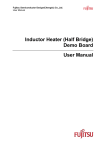
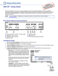
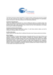
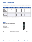
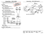
Setup Guide — MMX Series Setup Guide — MMX series (cont’d) Transmit (Tx) Receive (Rx) Ground ( ) Connect an RS-232 control device. Wire the connector as shown in the table at right. RS-232 Device Installation Operation — Creating ties Step 1 — Mounting Turn off or disconnect all equipment power sources and mount the MMX switcher as required. INPUTS 1 OUTPUTS 3 OUTPUTS 1 2 INPUTS 1 L 2 The drawings at right show the available connections. Your unit may look different. 4 INPUTS 1 2 L 1 4 L R L 2 5 R R R INPUTS OUTPUTS 3 R OUTPUTS 1 L R 1 4 L 2 5 R • Plug up to four or six video sources into the applicable input connector: S-video output connectors — A 4-pin mini DIN (Y/C) connector Composite video Input connectors — A female BNC connector • Plug up to four or six audio sources into the applicable audio input connectors: Two RCA connectors 5-pole captive screw connectors — Wire the connector as shown below. 2 4 R L R L L 1 2 R N Tip Ring Sleeve (s) Tip Ring VIDEO AUDIO INPUTS 1 2 3 4 RS-232 Control UTS 2 TP (high impedance) (high impedance) CONFIG If audio and video are tied from different inputs (audio breakaway), and if you select video and audio using the Configuration button, the Video LED and the LED for the selected video input light steadily and the Audio LED and the LED for the selected audio input blink. Balanced Stereo Input Unbalanced Stereo Input 1 2 2. Press and release the Configuration button as necessary to select either video and audio, video only, or audio only. 3. Press and release the button for the desired input. The LED for the selected input lights. R OUTPUTS R Do not tin the wires! R Tip Sleeve L A Tie is an input-to-output connection. An input can be tied to both outputs. An output can never be tied to more than one input. Create video and/or audio ties as follows: L L Tip Sleeve 2 Do not tin the wires! 1. Press and release the Outputs button to select the desired output. The LED for the selected output lights. L Step 2 — AV inputs N Transmit (Tx) Receive (Rx) Ground ( ) Bidirectional Tx Rx Step 6 — RS-232 connector This sheet provides quick start instructions for an experienced installer to set up and operate any of the MMX Series matrix switchers. OU 1 6 2 23 RSTX RX L 5 TS INPU 4 3 MAV 62 AV A RC 2 Step 3 — AV outputs UTS 1 1 TP OU 5 • Plug one or two video displays into the applicable output connectors: S-video output connector — A 4-pin mini DIN (Y/C) connector Composite video Input connector — A female BNC connector • Plug one or two audio devices into the applicable audio output connectors: Two RCA connectors (per output) 5-pole captive screw connectors — Wire the connector as shown below. TS INPU 2 3 6 1 4 R WE PO + Extron MMX 62 AV RCA 2 - C R X V 12 A MA 0.5 Matrix Switcher Connect the sleeves to ground (Gnd). Connecting the sleeve to a negative (-) terminal will damage the audio output circuits. Preview Monitor Videoconferencing System NO GROUND HERE. Do not tin the wires! Step 5 — Power Unbalanced Stereo Output Wire the 2-pole captive screw connector for the included external 12 VDC power supply as shown at right. Plug it into the switcher. Document Camera VCR Typical MMX 62 AV RCA application R Sleeve(s) Tip NO GROUND HERE. Tip Ring Sleeve(s) Tip Ring L Tip Balanced Stereo Output Smooth A Ridges A Captive Screw Connector Tie Wrap Extron USA - West SECTION A–A Power Supply Output Cord 3" 16 (5 mm) Max. Headquarters +800.633.9876 Inside USA / Canada Only +1.714.491.1500 +1.714.491.1517 FAX Extron USA - East Extron Europe Extron Asia Extron Japan Extron China Extron Middle East +800.633.9876 +800.3987.6673 +800.7339.8766 +81.3.3511.7655 +81.3.3511.7656 FAX +400.883.1568 +971.4.2991800 +971.4.2991880 FAX +1.919.863.1794 +1.919.863.1797 FAX +31.33.453.4040 +31.33.453.4050 FAX +65.6383.4400 +65.6383.4664 FAX Inside USA / Canada Only Inside Europe Only Inside Asia Only Inside China Only +86.21.3760.1568 +86.21.3760.1566 FAX 68-778-50 Rev. A 03 09